JP5803887B2 - robot - Google Patents
robotDownload PDFInfo
- Publication number
- JP5803887B2 JP5803887B2JP2012263994AJP2012263994AJP5803887B2JP 5803887 B2JP5803887 B2JP 5803887B2JP 2012263994 AJP2012263994 AJP 2012263994AJP 2012263994 AJP2012263994 AJP 2012263994AJP 5803887 B2JP5803887 B2JP 5803887B2
- Authority
- JP
- Japan
- Prior art keywords
- workpiece
- robot
- vertical articulated
- articulated robot
- processing
- Prior art date
- Legal status (The legal status is an assumption and is not a legal conclusion. Google has not performed a legal analysis and makes no representation as to the accuracy of the status listed.)
- Active
Links
Images


Classifications
- B—PERFORMING OPERATIONS; TRANSPORTING
- B25—HAND TOOLS; PORTABLE POWER-DRIVEN TOOLS; MANIPULATORS
- B25J—MANIPULATORS; CHAMBERS PROVIDED WITH MANIPULATION DEVICES
- B25J11/00—Manipulators not otherwise provided for
- B—PERFORMING OPERATIONS; TRANSPORTING
- B25—HAND TOOLS; PORTABLE POWER-DRIVEN TOOLS; MANIPULATORS
- B25J—MANIPULATORS; CHAMBERS PROVIDED WITH MANIPULATION DEVICES
- B25J9/00—Programme-controlled manipulators
- B25J9/0009—Constructional details, e.g. manipulator supports, bases
- B25J9/0018—Bases fixed on ceiling, i.e. upside down manipulators
- B—PERFORMING OPERATIONS; TRANSPORTING
- B25—HAND TOOLS; PORTABLE POWER-DRIVEN TOOLS; MANIPULATORS
- B25J—MANIPULATORS; CHAMBERS PROVIDED WITH MANIPULATION DEVICES
- B25J9/00—Programme-controlled manipulators
- B25J9/0093—Programme-controlled manipulators co-operating with conveyor means
- B—PERFORMING OPERATIONS; TRANSPORTING
- B65—CONVEYING; PACKING; STORING; HANDLING THIN OR FILAMENTARY MATERIAL
- B65G—TRANSPORT OR STORAGE DEVICES, e.g. CONVEYORS FOR LOADING OR TIPPING, SHOP CONVEYOR SYSTEMS OR PNEUMATIC TUBE CONVEYORS
- B65G57/00—Stacking of articles
- B65G57/02—Stacking of articles by adding to the top of the stack
- B65G57/03—Stacking of articles by adding to the top of the stack from above
Landscapes
- Engineering & Computer Science (AREA)
- Mechanical Engineering (AREA)
- Robotics (AREA)
- Manipulator (AREA)
Description
Translated fromJapaneseこの発明は、ロボットに関する。 The present invention relates to a robot.
従来、エンドエフェクタ(ハンド)が取り付けられるパラレルリンクロボットが知られている(たとえば、特許文献1参照)。上記特許文献1には、基礎部と、可動部と、基礎部と可動部とを連結する3つのリンク部とを備えるパラレルリンクロボットが開示されている。このパラレルリンクロボットの可動部には、エンドエフェクタが取り付けられるように構成されている。そして、3つのリンク部が駆動部により駆動されて、曲げ伸ばしされることにより、可動部が上下されて、エンドエフェクタが所定の位置に位置決めされるように構成されている。また、パラレルリンクロボットは、一般的には、エンドエフェクタにより処理(把持など)されるワークの直上に配置される。 Conventionally, a parallel link robot to which an end effector (hand) is attached is known (for example, see Patent Document 1).
しかしながら、上記特許文献1に記載のパラレルリンクロボットでは、パラレルリンクロボットが、ワークの直上に配置されている場合、パラレルリンクロボットのリンク部を縮ませてパラレルリンクロボットの可動部(エンドエフェクタ)を上方に移動させても、パラレルリンクロボットの可動範囲が比較的小さいため、パラレルリンクロボットが、ユーザがワークに対して処理を行う動作の妨げになるという問題点がある。 However, in the parallel link robot described in
この発明は、上記のような課題を解決するためになされたものであり、この発明の1つの目的は、ユーザがワークに対して処理を行う動作の妨げになるのを抑制することが可能なロボットを提供することである。 The present invention has been made to solve the above-described problems, and one object of the present invention is to prevent a user from interfering with an operation for performing processing on a workpiece. Is to provide a robot.
上記目的を達成するために、第1の局面によるロボットは、ワークに対して処理を行うためのハンドと、ハンドが取り付けられ、天吊り状態で配置されている垂直多関節型ロボット本体とを備え、垂直多関節型ロボット本体は、平面視において、ワークの搬送経路とオーバーラップしない状態で搬送経路からずらして配置されており、垂直多関節型ロボット本体は、垂直多関節型ロボット本体を天吊り状態に取り付ける取付け部を含み、取付け部は、平面視において、ユーザがワークに対して処理を行う作業位置から搬送経路に沿った方向にずらした位置に固定的に取り付けられており、ワークは、食品、薬品および化粧品のうちの少なくとも1つを含み、ロボットアームを含む垂直多関節型ロボット本体は、ハンドによるワークに対して処理を行う動作中、平面視において、ワークの搬送経路とオーバーラップしない状態で動作されるように構成されている。
第2の局面によるロボットは、ワークに対して処理を行うためのハンドと、ハンドが取り付けられ、天吊り状態で配置されている垂直多関節型ロボット本体とを備え、垂直多関節型ロボット本体は、平面視において、ワークの搬送経路とオーバーラップしない状態で搬送経路からずらして配置されており、垂直多関節型ロボット本体は、垂直多関節型ロボット本体を天吊り状態に取り付ける取付け部を含み、取付け部は、平面視において、ユーザがワークに対して処理を行う作業位置から搬送経路に沿った方向にずらした位置に固定的に取り付けられており、垂直多関節型ロボット本体は、ワークに対する処理を行っていない場合、天吊り状態で配置されている垂直多関節型ロボット本体が上方に移動されることにより、ユーザがワークに対して処理を行う動作の妨げにならない位置に退避されるように構成されており、ロボットアームを含む垂直多関節型ロボット本体は、ハンドによるワークに対して処理を行う動作中、平面視において、ワークの搬送経路とオーバーラップしない状態で動作されるように構成されている。In order to achieve the above object, a robot according to a first aspect includes a hand for performing processing on a workpiece, and a vertical articulated robot body to which the hand is attached and arranged in a suspended state. The vertical articulated robot body is arranged so as to be shifted from the conveyance path in plan view without overlapping the workpiece conveyance path. The vertical articulated robot body is suspended from the vertical articulated robot body. Including a mounting portion attached to the state, and the mounting portion is fixedly mounted at a position shifted in a direction along the conveyance path from a work position where the user performs processing on the workpiece in plan view. food,seen at least 1 Tsuo含of the chemicals andcosmetics, vertical articulated robot body including a robot arm, punished for the work by hand During operation of performing, in a plan view, and is configured to be operated in a state where no conveying path overlaps the workpiece.
A robot according to a second aspect includes a hand for performing processing on a workpiece, and a vertical articulated robot main body to which the hand is attached and arranged in a suspended state. In the plan view, the vertical articulated robot main body is arranged to be shifted from the transport path without overlapping the work transport path, and the vertical articulated robot main body includes a mounting portion for mounting the vertical articulated robot main body in a suspended state. The mounting portion is fixedly mounted at a position shifted in a direction along the transfer path from a work position at which the user performs processing on the workpiece in plan view, and the vertical articulated robot body performs processing on the workpiece. If the vertical articulated robot body that is suspended from the ceiling is moved upward, the userIt is configured to be retracted to a position not to interfere with operation of performing processingTe, vertical articulated type robot body including a robot arm, in operation to perform the processing on the workpiece by the hand, in a plan view, a work It is configured to be operated in a state where it does not overlap with the transport path .
この第1の局面によるロボットでは、上記のように、垂直多関節型ロボット本体を、平面視において、ワークの搬送経路とオーバーラップしない状態で搬送経路からずらして配置することによって、ユーザがワークに対して処理を行うためにユーザが移動する経路からロボットをずらすことができる。その結果、ロボットが、ユーザがワークに対して処理を行う動作の妨げになるのを抑制することができる。 In the robot according to the first aspect, as described above, the vertical articulated robot main body is shifted from the transfer path in a plan view so as not to overlap the transfer path of the work. On the other hand, the robot can be shifted from the path along which the user moves in order to perform processing. As a result, it is possible to prevent the robot from interfering with the operation of the user performing processing on the workpiece.
第3の局面によるロボットは、ワークに対して処理を行うためのハンドと、ハンドが取り付けられ、天吊り状態で配置されている垂直多関節型ロボット本体とを備え、垂直多関節型ロボット本体は、ワークに対する処理を行っていない場合、天吊り状態で配置されている垂直多関節型ロボット本体が上方に移動されることにより、ユーザがワークに対して処理を行う動作の妨げにならない位置に退避されるように構成されており、垂直多関節型ロボット本体は、垂直多関節型ロボット本体を天吊り状態に取り付ける取付け部を含み、取付け部は、平面視において、ユーザがワークに対して処理を行う作業位置から搬送経路に沿った方向にずらした位置に固定的に取り付けられており、ワークは、食品、薬品および化粧品のうちの少なくとも1つを含み、ロボットアームを含む垂直多関節型ロボット本体は、ハンドによるワークに対して処理を行う動作中、平面視において、ワークの搬送経路とオーバーラップしない状態で動作されるように構成されている。A robot according to a third aspect includes a hand for performing processing on a workpiece, and a vertical articulated robot main body to which the hand is attached and arranged in a suspended state. When the workpiece is not being processed, the vertical articulated robot body arranged in a suspended state is moved upward so that the user can move to a position that does not interfere with the operation of the workpiece. The vertical articulated robot main body includes a mounting portion for mounting the vertical articulated robot main body in a suspended state, and the mounting portion performs processing on the workpiece in plan view. The workpiece is fixedly attached at a position shifted in a direction along the conveyance path from the work position to be performed, and the workpiece is at least one of food, medicine and cosmetics.Only including, a vertical articulated robot body including a robot arm, in operation to perform the processing on the workpiece by the hand, in a plan view, is configured to be operated in a state where no conveying path overlaps the workpiece Yes .
この第2の局面によるロボットでは、ワークに対する処理を行っていない場合、天吊り状態で配置されている垂直多関節型ロボット本体を上方に移動することにより、垂直多関節型ロボット本体を、ユーザがワークに対して処理を行う動作の妨げにならない位置に退避する。パラレルリンクロボットが、ワークの直上に配置されている場合では、パラレルリンクロボットのリンク部を縮ませてパラレルリンクロボットの可動部(エンドエフェクタ)を上方に移動させても、パラレルリンクロボットの可動範囲が比較的小さいため、パラレルリンクロボットが、ユーザがワークに対して処理を行う動作の妨げになる。一方、ロボットを、可動範囲の比較的大きい垂直多関節型ロボット本体により構成することにより、垂直多関節型ロボット本体は、可動範囲が比較的大きいので、容易に、垂直多関節型ロボット本体を、ユーザがワークに対して処理を行う動作の妨げにならない位置に退避させることができる。 In the robot according to the second aspect, when the workpiece is not processed, the vertical articulated robot main body is moved by the user by moving the vertical articulated robot main body arranged in a suspended state upward. Retreat to a position that does not interfere with the operation of processing the workpiece. When the parallel link robot is arranged immediately above the workpiece, the movable range of the parallel link robot can be reduced even if the movable portion (end effector) of the parallel link robot is moved upward by contracting the link portion of the parallel link robot. Is relatively small, the parallel link robot hinders the user's operation to process the workpiece. On the other hand, by configuring the robot with a vertical articulated robot body having a relatively large movable range, the vertical articulated robot body has a relatively large movable range. The user can retreat to a position that does not interfere with the operation of processing the workpiece.
上記のように構成することによって、ロボットが、ユーザがワークに対して処理を行う動作の妨げになるのを抑制することができる。 By configuring as described above, it is possible to prevent the robot from interfering with the operation of the user performing the process on the workpiece.
以下、本実施形態を図面に基づいて説明する。 Hereinafter, the present embodiment will be described with reference to the drawings.
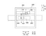
まず、図1を参照して、本実施形態のロボット100の構成について説明する。 First, the configuration of the
図1に示すように、本実施形態では、ロボット100は、ロボット100を支持する支持部材(門型)200に天吊り状態で配置されている。具体的には、ロボット100は、支持部材200に設けられる梁部201に後述するロボット100の基台11が取り付けられることにより、支持部材200に天吊り状態で配置されている。また、支持部材200の梁部201以外の天井の部分には、開口部202が形成されている。 As shown in FIG. 1, in the present embodiment, the
支持部材200の内部には、下段コンベア203と上段コンベア204とが配置されている。下段コンベア203は、内部に食品が収納されている下箱400を矢印X1方向側から矢印X2方向側に向かって搬送するように構成されている。そして、下段コンベア203は、矢印X1方向側から搬送された下箱400が所定の位置(ロボット100の近傍)に到達した際に停止するように構成されている。また、下段コンベア203には、下箱400を所定の位置に位置決めするための位置決め部材(図示せず)が設けられている。なお、下段コンベア203および上段コンベア204は、「コンベア」の一例である。また、下箱400は、「ワーク」の一例である。 A
上段コンベア204は、下箱400に被せられる上箱401を矢印X1方向側から矢印X2方向側に向かって搬送するように構成されている。そして、上段コンベア204は、矢印X1方向側から搬送された上箱401が所定の位置(ロボット100の近傍)に到達した際に停止するように構成されている。また、上段コンベア204には、上箱401を所定の位置に位置決めするための位置決め部材(図示せず)が設けられている。また、上段コンベア204は、下段コンベア203よりも上方に配置されている。すなわち、本実施形態では、上箱401が下箱400に被せられる前には、上箱401は、下箱400よりも高い位置に配置されるように構成されている。また、下段コンベア203は、支持部材200を矢印X1方向側から矢印X2方向側に向かって貫通するように設けられている。一方、上段コンベア204は、支持部材200の矢印X1方向側から支持部材200の内部(ロボット100の近傍)まで設けられている。なお、上箱401は、「ワーク」の一例である。 The
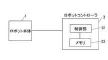
図1および図2に示すように、ロボット100は、垂直多関節ロボットからなる。このロボット100は、ロボット本体1と、ロボット本体1の先端に取り付けられ、上箱401および下箱400に対して処理を行うためのハンド2とを含む。また、ロボット本体1は、基台11と、基台11に取り付けられるロボットアーム12と含む。ロボットアーム12は、6自由度を有して構成されている。なお、ロボット本体1は、「垂直多関節型ロボット本体」の一例である。 As shown in FIGS. 1 and 2, the
ロボットアーム12は、複数のアーム構造体を有しており、ロボット100の設置面(梁部201)に対して垂直な回転軸A1まわりにアーム構造体12aが基台11に対して回転可能に連結されている。アーム構造体12bは、回転軸A1に対して垂直な回転軸A2まわりに回転可能にアーム構造体12aに連結されている。アーム構造体12cは、回転軸A2に対して平行な回転軸A3まわりに回転可能にアーム構造体12bに連結されている。アーム構造体12dは、回転軸A3に対して垂直な回転軸A4まわりに回転可能にアーム構造体12cに連結されている。アーム構造体12eは、回転軸A4に対して垂直な回転軸A5まわりに回転可能にアーム構造体12dに連結されている。アーム構造体12fは、回転軸A5に対して垂直な回転軸A6まわりに回転可能にアーム構造体12eに連結されている。なお、ここでいう「平行」「垂直」は、厳密な意味の「平行」および「垂直」だけでなく、「平行」および「垂直」から少しずれているものも含む広い意味である。各回転軸A1〜A6にはそれぞれサーボモータ(関節)が設けられており、各サーボモータは、それぞれの回転位置を検出するエンコーダを有している。各サーボモータは、ロボットコントローラ3(図5参照)に接続されており、ロボットコントローラ3の指令に基づいて各サーボモータが動作するように構成されている。 The
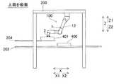
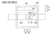
ここで、本実施形態では、図3に示すように、ロボット本体1は、平面視において(矢印Z1方向から見て)、上箱401および下箱400の搬送経路(下段コンベア203および上段コンベア204)とオーバーラップしない状態で搬送経路からずらして配置されている。また、ロボット本体1は、平面視において、上箱401および下箱400が搬送される方向(X方向)と略直交する方向(矢印Y1方向)に、上箱401および下箱400の搬送経路とオーバーラップしない状態で搬送経路からずらして配置されている。具体的には、ロボット本体1の基台11は、平面視において、支持部材200のY方向の中央部よりも矢印Y1方向側に設けられた梁部201に取り付けられている。そして、ロボット本体1のロボットアーム12は、平面視において、上箱401および下箱400の搬送経路(下段コンベア203および上段コンベア204)とオーバーラップしない状態で搬送経路から矢印Y1方向側にずらして配置されている。なお、本実施形態では、ロボット本体1(基台11およびロボットアーム12)は、ハンド2による上箱401および下箱400に対しての処理動作中(上箱401を下箱400に被せる動作中)および待機時(ロボット本体1の処理動作前、処理動作後)の両方に、平面視において、上箱401および下箱400の搬送経路とオーバーラップしない状態で動作するように構成されている。一方、ハンド2は、上箱401および下箱400に対しての処理動作中、平面視において、上箱401および下箱400の搬送経路とオーバーラップした状態で動作するように構成されている。 Here, in the present embodiment, as shown in FIG. 3, the
また、本実施形態では、図4および図6に示すように、上箱401が下箱400に被せられる前には、上箱401は、下箱400よりも高い位置に配置されるように構成されている。すなわち、上箱401は、下箱400が配置される下段コンベア203よりも高い位置に配置されている上段コンベア204に配置されている。そして、ロボット本体1が、上箱401および下箱400の搬送経路とオーバーラップしない状態で搬送経路からずらして天吊りされた状態で、ハンド2により、高い位置に配置された上箱401を保持(吸着)(図6参照)した後、上箱401を下箱400に被せる処理動作(図8参照)を行うように構成されている。 Further, in the present embodiment, as shown in FIGS. 4 and 6, the
図5に示すように、ロボット本体1には、ロボット本体1(ロボット100)の全体の動作を制御するためのロボットコントローラ3が接続されている。また、ロボットコントローラ3には、制御部31と、メモリ32とが設けられている。 As shown in FIG. 5, the
次に、図3、図4および図6〜図10を参照して、本実施形態によるロボット100の動作(処理動作時および退避時)について説明する。 Next, with reference to FIGS. 3, 4 and 6 to 10, the operation of the
(処理動作時)
まず、図3、図4および図6に示すように、上箱401が、上段コンベア204により、所定の位置(ロボット100の近傍)に搬送されるとともに、下箱400が、下段コンベア203により、所定の位置(ロボット100の近傍)に搬送される。次に、ロボットアーム12が移動されるとともに、ハンド2により、上箱401が吸着(保持)される。(When processing)
First, as shown in FIGS. 3, 4, and 6, the
次に、図7および図8に示すように、ロボットアーム12が矢印X2方向に移動されるとともに、上箱401が下箱400に被せられる。この際、ロボット本体1は、ハンド2による上箱401の吸着動作中および上箱401を下箱400に被せる動作中、平面視において、上箱401および下箱400の搬送経路とオーバーラップしない状態で動作(移動)される。 Next, as shown in FIGS. 7 and 8, the
(退避時)
本実施形態では、図9および図10に示すように、ロボット本体1は、上箱401および下箱400に対する処理を行っていない場合、天吊り状態で配置されているロボット本体1が上方に移動されることにより、ユーザ300が上箱401および下箱400に対して処理を行う動作の妨げにならない位置に退避される。また、ロボット本体1は、ユーザ300が上箱401および下箱400に対して処理を行うために、ユーザ300が移動する経路(動線)と重ならない位置に退避される。たとえば、図10に示すように、ユーザ300が上箱401を下箱400に被せる動作(作業)を行うために、ユーザ300が上箱401および下箱400に近づく経路A、および、ユーザ300が上箱401を下箱400に被せる動作(作業)を行う作業位置Bからずらした位置にロボット本体1およびハンド2が退避される。このとき、ロボット本体1およびハンド2は、支持部材200の開口部202から上方(矢印Z1方向)に突出した状態で退避される。なお、ロボット本体1およびハンド2の退避は、ロボット本体1およびハンド2の故障時、および、予め教示されている動作では処理できないワークが搬送されて、ユーザ300の手作業によって処理動作が行われる場合など行われる。(When evacuating)
In this embodiment, as shown in FIGS. 9 and 10, when the
本実施形態では、上記のように、種直多関節ロボットからなるロボット100のロボット本体1を、平面視において、上箱401および下箱400の搬送経路とオーバーラップしない状態で搬送経路からずらして配置することによって、ユーザ300が上箱401および下箱400に対して処理を行うためにユーザ300が移動する経路からロボット100をずらすことができる。その結果、ロボット100が、ユーザ300が上箱401および下箱400に対して処理を行う動作の妨げになるのを抑制することができる。 In the present embodiment, as described above, the
また、本実施形態では、上記のように、ロボット本体1を、平面視において、上箱401および下箱400が搬送される方向と略直交する方向に、上箱401および下箱400の搬送経路とオーバーラップしない状態で搬送経路からずらして配置する。これにより、容易に、ロボット本体1を、上箱401および下箱400の搬送経路とオーバーラップしない状態で搬送経路からずらして配置することができる。 Further, in the present embodiment, as described above, the robot
また、本実施形態では、上記のように、ロボット本体1を、ハンド2による上箱401および下箱400に対しての処理動作中および待機時の両方に、平面視において、上箱401および下箱400の搬送経路とオーバーラップしない状態で動作するように構成する。これにより、ロボット本体1の動作範囲を小さくしながら、上箱401および下箱400に対して処理することができる。 Further, in the present embodiment, as described above, the robot
また、本実施形態では、上記のように、上箱401および下箱400を、それぞれ、上段コンベア204および下段コンベア203上を搬送されるように構成し、ロボット本体1を、平面視において、上段コンベア204および下段コンベア203とオーバーラップしない状態で上段コンベア204および下段コンベア203からずらして配置する。これにより、上段コンベア204および下段コンベア203上を搬送される上箱401および下箱400に対してユーザ300が処理を行うためにユーザ300が移動する経路から、ロボット100をずらすことができる。 Further, in the present embodiment, as described above, the
また、本実施形態では、上記のように、上箱401および下箱400には、食品が収納され、ロボット本体1が、上箱401および下箱400の搬送経路とオーバーラップしない状態で搬送経路からずらして天吊りされた状態で、ハンド2により、上箱401を下箱400に被せる処理動作を行うように構成する。これにより、食品が収納される上箱401および下箱400に対してユーザ300が処理を行うためにユーザ300が移動する経路から、ロボット100をずらすことができる。 In the present embodiment, as described above, food is stored in the
また、本実施形態では、上記のように、上箱401が下箱400に被せられる前には、上箱401は、下箱400よりも高い位置に配置されるように構成されており、ロボット本体1が、上箱401および下箱400の搬送経路とオーバーラップしない状態で搬送経路からずらして天吊りされた状態で、ハンド2により、高い位置に配置された上箱401を保持した後、上箱401を下箱400に被せる処理動作を行うように構成する。これにより、上箱401が予め下箱400よりも高い位置に配置されているので、上箱401と下箱400とが同じ位置に配置されている場合と異なり、上箱401を下箱400に被せるために上箱401を上方に持ち上げる動作を省略することができる。その結果、ロボット100の処理作業のタクトタイムを短縮することができる。 In the present embodiment, as described above, before the
また、本実施形態では、上記のように、上箱401および下箱400に対する処理を行っていない場合、天吊り状態で配置されているロボット本体1を上方に移動することにより、ロボット本体1を、ユーザ300が上箱401および下箱400に対して処理を行う動作の妨げにならない位置に退避するように構成する。パラレルリンクロボットが、上箱401および下箱400の直上に配置されている場合では、パラレルリンクロボットのリンク部を縮ませてパラレルリンクロボットの可動部(エンドエフェクタ)を上方に移動させても、パラレルリンクロボットの可動範囲が比較的小さいため、パラレルリンクロボットが、ユーザが上箱401および下箱400に対して処理を行う動作の妨げになる。一方、ロボット100を、可動範囲が比較的大きい垂直多関節型のロボット本体1により構成することにより、容易に、ロボット本体1を、ユーザが上箱401および下箱400に対して処理を行う動作の妨げにならない位置に退避させることができる。 Moreover, in this embodiment, when the process with respect to the
また、本実施形態では、上記のように、ロボット本体1を、ユーザ300が上箱401および下箱400に対して処理を行うために、ユーザ300が移動する経路と重ならない位置に退避するように構成する。これにより、ユーザ300による上箱401および下箱400に対する処理動作に加えて、ユーザ300の上箱401および下箱400に対する処理を行う位置までの移動動作および退避動作に対しても、ロボット本体1が妨げになるのを抑制することができる。 Further, in the present embodiment, as described above, the
なお、今回開示された実施形態は、すべての点で例示であって制限的なものではないと考えられるべきである。本発明の範囲は、上記した実施形態の説明ではなく特許請求の範囲によって示され、さらに特許請求の範囲と均等の意味および範囲内でのすべての変更が含まれる。 The embodiment disclosed this time should be considered as illustrative in all points and not restrictive. The scope of the present invention is shown not by the above description of the embodiments but by the scope of claims for patent, and further includes all modifications within the meaning and scope equivalent to the scope of claims for patent.
たとえば、上記実施形態では、支持部材の梁部(天井部分)にロボットが天吊り状態で配置されている例を示したが、たとえば、床面に対して垂直な壁にロボットを天吊り状態で配置してもよい。また、ロボットが、ロボットが配置される建物の天井に配置されていてもよい。 For example, in the above-described embodiment, an example is shown in which the robot is suspended from the beam portion (ceiling portion) of the support member. However, for example, the robot is suspended from a wall perpendicular to the floor surface. You may arrange. Further, the robot may be arranged on the ceiling of the building where the robot is arranged.
また、上記実施形態では、ロボットのロボットアームが6自由度を有する例を示したが、たとえば、ロボットアームが6自由度以外の自由度(5自由度、7自由度など)を有していてもよい。 In the above embodiment, the robot arm of the robot has 6 degrees of freedom. However, for example, the robot arm has degrees of freedom other than 6 degrees of freedom (5 degrees of freedom, 7 degrees of freedom, etc.). Also good.
また、上記実施形態では、ロボット本体を、平面視において、上箱および下箱が搬送される方向と略直交する矢印Y1方向(上段コンベアおよび下段コンベアの矢印Y1方向、図3参照)に配置する例を示したが、たとえば、ロボット本体を、上段コンベアおよび下段コンベアの矢印Y2方向に配置してもよい。 In the above embodiment, the robot body is arranged in the direction of arrow Y1 that is substantially orthogonal to the direction in which the upper box and the lower box are transported (see the arrow Y1 direction of the upper and lower conveyors, see FIG. 3). Although an example is shown, for example, the robot main body may be arranged in the direction of arrow Y2 of the upper conveyor and the lower conveyor.
また、上記実施形態では、上箱および下箱に食品が収納される例を示したが、たとえば、上箱および下箱に食品以外の薬品や化粧品などを収納してもよい。 In the above embodiment, an example is shown in which food is stored in the upper box and the lower box. However, for example, chemicals and cosmetics other than food may be stored in the upper box and the lower box.
また、上記実施形態では、ハンドにより、上箱を下箱に被せる処理動作を行う例を示したが、たとえば、ハンドにより、上箱および下箱以外のワークに対する処理動作を行うように構成してもよい。 Moreover, in the said embodiment, although the example which performs the processing operation which covers an upper box on a lower box with a hand was shown, for example, it constituted so that processing operation to works other than an upper box and a lower box might be performed with a hand. Also good.
また、上記実施形態では、上箱が下箱に被せられる前には、上箱が下箱よりも高い位置に配置される例を示したが、たとえば、上箱と下箱とを同じ高さに配置してもよいし、上箱を下箱よりも低い位置に配置してもよい。 In the above embodiment, the upper box is disposed at a position higher than the lower box before the upper box is put on the lower box. For example, the upper box and the lower box are at the same height. The upper box may be arranged at a position lower than the lower box.
また、上記実施形態では、支持部材(ロボットの近傍)に上段コンベアと下段コンベアとが1つずつ配置されている例を示したが、たとえば、支持部材(ロボットの近傍)に上段コンベアと下段コンベアとを複数ずつ配置(たとえば、ロボットの矢印Y2方向側(図3参照)に、上段コンベアと下段コンベアとを2つずつ2列に配置)して、それぞれのコンベアから搬送される上箱および下箱に対して、ロボットが処理動作を行うように構成してもよい。 In the above embodiment, an example is shown in which one upper conveyor and one lower conveyor are arranged on the support member (near the robot), but for example, the upper conveyor and the lower conveyor on the support member (near the robot). (For example, two upper conveyors and two lower conveyors are arranged in two rows on the arrow Y2 direction side of the robot (see FIG. 3)), and upper boxes and lower The robot may be configured to perform a processing operation on the box.
また、上記実施形態では、ロボット本体が上箱および下箱に対する処理を行っていない場合、ロボット本体およびハンドが、支持部材の開口部から上方に突出した状態で退避される例を示したが、たとえば、ロボット本体が上箱および下箱に対する処理を行っていない場合、ロボット本体およびハンドを支持部材の天井に対して水平な状態で退避するように構成してもよい。 In the above embodiment, when the robot body does not perform processing on the upper box and the lower box, the robot body and the hand are retracted in a state of protruding upward from the opening of the support member. For example, when the robot main body is not processing the upper box and the lower box, the robot main body and the hand may be retracted in a state of being horizontal with respect to the ceiling of the support member.
1 ロボット本体(垂直多関節型ロボット本体)
2 ハンド
100 ロボット
203 下段コンベア(コンベア)
204 上段コンベア(コンベア)
400 下箱(ワーク)
401 上箱(ワーク)1 Robot body (vertically articulated robot body)
2
204 Upper conveyor (conveyor)
400 Lower box (work)
401 Upper box (work)
Claims (9)
Translated fromJapanese前記ハンドが取り付けられ、天吊り状態で配置されている垂直多関節型ロボット本体とを備え、
前記垂直多関節型ロボット本体は、平面視において、前記ワークの搬送経路とオーバーラップしない状態で前記搬送経路からずらして配置されており、
前記垂直多関節型ロボット本体は、前記垂直多関節型ロボット本体を天吊り状態に取り付ける取付け部を含み、
前記取付け部は、平面視において、ユーザが前記ワークに対して処理を行う作業位置から前記搬送経路に沿った方向にずらした位置に固定的に取り付けられており、
前記ワークは、食品、薬品および化粧品のうちの少なくとも1つを含み、
ロボットアームを含む前記垂直多関節型ロボット本体は、前記ハンドによる前記ワークに対して処理を行う動作中、平面視において、前記ワークの前記搬送経路とオーバーラップしない状態で動作されるように構成されている、ロボット。A hand for processing the workpiece;
A vertical articulated robot body mounted with the hand and arranged in a suspended state,
The vertical articulated robot body is arranged so as to be shifted from the transport path in a state of not overlapping the work transport path in plan view,
The vertical articulated robot body includes a mounting portion for attaching the vertical articulated robot body to a suspended state,
The mounting portion is fixedly mounted at a position shifted in a direction along the transport path from a work position at which a user performs processing on the workpiece in plan view.
The work,seen at least 1 Tsuo含of food, drugs andcosmetics,
The vertical articulated robot main body including a robot arm is configured to be operated in a state of not overlapping with the transport path of the workpiece in a plan view during an operation of performing processing on the workpiece by the hand. A robot.
前記垂直多関節型ロボット本体は、平面視において、前記コンベアとオーバーラップしない状態で前記コンベアからずらして配置されている、請求項1〜3のいずれか1項に記載のロボット。The workpiece is configured to be conveyed on a conveyor,
The robot according to any one of claims 1 to 3, wherein the vertical articulated robot main body is arranged so as to be shifted from the conveyor in a state of not overlapping the conveyor in a plan view.
前記垂直多関節型ロボット本体が、前記ワークの搬送経路とオーバーラップしない状態で前記搬送経路からずらして天吊りされた状態で、前記ハンドにより、前記上箱を前記下箱に被せる処理動作を行うように構成されている、請求項1〜4のいずれか1項に記載のロボット。The workpiece includes a lower box in which at least one of the food, the medicine, and the cosmetic is stored, and an upper box that covers the lower box,
In the state where the vertical articulated robot body is suspended from the transfer path without being overlapped with the transfer path of the workpiece, a processing operation of covering the upper box with the lower box by the hand is performed. The robot according to claim 1, configured as described above.
前記垂直多関節型ロボット本体が、前記ワークの搬送経路とオーバーラップしない状態で前記搬送経路からずらして天吊りされた状態で、前記ハンドにより、前記高い位置に配置された上箱を保持した後、前記上箱を前記下箱に被せる処理動作を行うように構成されている、請求項5に記載のロボット。Before the upper box is put on the lower box, the upper box is configured to be arranged at a higher position than the lower box,
After holding the upper box placed at the high position by the hand in a state where the vertical articulated robot main body is suspended from the transport path while being not suspended from the work transport path. The robot according to claim 5, wherein the robot is configured to perform a processing operation of placing the upper box on the lower box.
前記ハンドが取り付けられ、天吊り状態で配置されている垂直多関節型ロボット本体とを備え、
前記垂直多関節型ロボット本体は、平面視において、前記ワークの搬送経路とオーバーラップしない状態で前記搬送経路からずらして配置されており、
前記垂直多関節型ロボット本体は、前記垂直多関節型ロボット本体を天吊り状態に取り付ける取付け部を含み、
前記取付け部は、平面視において、ユーザが前記ワークに対して処理を行う作業位置から前記搬送経路に沿った方向にずらした位置に固定的に取り付けられており、
前記垂直多関節型ロボット本体は、前記ワークに対する処理を行っていない場合、天吊り状態で配置されている前記垂直多関節型ロボット本体が上方に移動されることにより、ユーザが前記ワークに対して処理を行う動作の妨げにならない位置に退避されるように構成されており、
ロボットアームを含む前記垂直多関節型ロボット本体は、前記ハンドによる前記ワークに対して処理を行う動作中、平面視において、前記ワークの前記搬送経路とオーバーラップしない状態で動作されるように構成されている、ロボット。A hand for processing the workpiece;
A vertical articulated robot body mounted with the hand and arranged in a suspended state,
The vertical articulated robot body is arranged so as to be shifted from the transport path in a state of not overlapping the work transport path in plan view,
The vertical articulated robot body includes a mounting portion for attaching the vertical articulated robot body to a suspended state,
The mounting portion is fixedly mounted at a position shifted in a direction along the transport path from a work position at which a user performs processing on the workpiece in plan view.
When the vertical articulated robot main body is not processing the workpiece, the vertical articulated robot main body arranged in a suspended state is moved upward so that the user can It is configured to be retracted to a position that does not interfere with the processing operation,
The vertical articulated robot main body including a robot arm is configured to be operated in a state of not overlapping with the transport path of the workpiece in a plan view during an operation of performing processing on the workpiece by the hand. A robot.
前記ハンドが取り付けられ、天吊り状態で配置されている垂直多関節型ロボット本体とを備え、
前記垂直多関節型ロボット本体は、前記ワークに対する処理を行っていない場合、天吊り状態で配置されている前記垂直多関節型ロボット本体が上方に移動されることにより、ユーザが前記ワークに対して処理を行う動作の妨げにならない位置に退避されるように構成されており、
前記垂直多関節型ロボット本体は、前記垂直多関節型ロボット本体を天吊り状態に取り付ける取付け部を含み、
前記取付け部は、平面視において、ユーザが前記ワークに対して処理を行う作業位置から前記搬送経路に沿った方向にずらした位置に固定的に取り付けられており、
前記ワークは、食品、薬品および化粧品のうちの少なくとも1つを含み、ロボットアームを含む前記垂直多関節型ロボット本体は、前記ハンドによる前記ワークに対して処理を行う動作中、平面視において、前記ワークの前記搬送経路とオーバーラップしない状態で動作されるように構成されている、ロボット。A hand for processing the workpiece;
A vertical articulated robot body mounted with the hand and arranged in a suspended state,
When the vertical articulated robot main body is not processing the workpiece, the vertical articulated robot main body arranged in a suspended state is moved upward so that the user can It is configured to be retracted to a position that does not interfere with the processing operation,
The vertical articulated robot body includes a mounting portion for attaching the vertical articulated robot body to a suspended state,
The mounting portion is fixedly mounted at a position shifted in a direction along the transport path from a work position at which a user performs processing on the workpiece in plan view.
The workpiece is food,viewed at least Tsuo含of drugs andcosmetics, the vertical articulated robot body including a robotic arm during operation of performing processing on the by the handwork, in plan view, A robotconfigured to be operated in a state in which the workpiece does not overlap the conveyance path .
Priority Applications (4)
| Application Number | Priority Date | Filing Date | Title |
|---|---|---|---|
| JP2012263994AJP5803887B2 (en) | 2012-12-03 | 2012-12-03 | robot |
| EP13190021.9AEP2737980A1 (en) | 2012-12-03 | 2013-10-24 | Robot disposed adjacent to a conveyance path and retractable in a parking position |
| CN201310634591.3ACN103846906A (en) | 2012-12-03 | 2013-12-02 | Robot |
| US14/094,614US20140154041A1 (en) | 2012-12-03 | 2013-12-02 | Robot |
Applications Claiming Priority (1)
| Application Number | Priority Date | Filing Date | Title |
|---|---|---|---|
| JP2012263994AJP5803887B2 (en) | 2012-12-03 | 2012-12-03 | robot |
Publications (2)
| Publication Number | Publication Date |
|---|---|
| JP2014108487A JP2014108487A (en) | 2014-06-12 |
| JP5803887B2true JP5803887B2 (en) | 2015-11-04 |
Family
ID=49485554
Family Applications (1)
| Application Number | Title | Priority Date | Filing Date |
|---|---|---|---|
| JP2012263994AActiveJP5803887B2 (en) | 2012-12-03 | 2012-12-03 | robot |
Country Status (4)
| Country | Link |
|---|---|
| US (1) | US20140154041A1 (en) |
| EP (1) | EP2737980A1 (en) |
| JP (1) | JP5803887B2 (en) |
| CN (1) | CN103846906A (en) |
Families Citing this family (8)
| Publication number | Priority date | Publication date | Assignee | Title |
|---|---|---|---|---|
| DE102015104324B4 (en)* | 2015-03-23 | 2025-08-14 | Krones Aktiengesellschaft | Method and device for handling articles, piece goods or containers |
| DE202015104886U1 (en)* | 2015-09-15 | 2016-12-16 | Kuka Systems Gmbh | handling device |
| CN105463458B (en)* | 2016-01-11 | 2018-01-09 | 安徽工业大学 | A kind of automatic application of slip device |
| JP2018075689A (en)* | 2016-11-11 | 2018-05-17 | Ntn株式会社 | Operation device and double arm type operation device |
| JP6705976B2 (en)* | 2017-05-11 | 2020-06-03 | 株式会社安川電機 | Robot, robot control method, workpiece manufacturing method |
| DE102017122703A1 (en)* | 2017-08-21 | 2019-02-21 | Weber Maschinenbau Gmbh Breidenbach | Device for loading products |
| CN111716378B (en)* | 2020-05-19 | 2021-12-03 | 昆明理工大学 | Double-sided film tearing equipment |
| JP7583384B2 (en)* | 2021-03-25 | 2024-11-14 | マルシン機工株式会社 | Lid mounting device and lid mounting method |
Family Cites Families (53)
| Publication number | Priority date | Publication date | Assignee | Title |
|---|---|---|---|---|
| GB966609A (en)* | 1965-03-10 | 1900-01-01 | ||
| US3792782A (en)* | 1971-12-10 | 1974-02-19 | Programmed & Remote Syst Corp | Grapple assembly |
| US3904042A (en)* | 1974-02-25 | 1975-09-09 | Westinghouse Electric Corp | Manipulator apparatus |
| JPS55152565A (en)* | 1979-05-18 | 1980-11-27 | Tokico Ltd | Robot for coating operation |
| DE78113T1 (en)* | 1981-10-26 | 1983-09-15 | United Kingdom Atomic Energy Authority, London | MANIPULATOR. |
| JPS61146482A (en)* | 1984-12-20 | 1986-07-04 | 工業技術院長 | Controller for different-structure different freedom-degree bilateral-master/slave-manipulator |
| JPS62246490A (en)* | 1986-04-17 | 1987-10-27 | 日産自動車株式会社 | Method of restoring facility of production line |
| JPH04310384A (en)* | 1991-04-09 | 1992-11-02 | Toyota Motor Corp | double arm robot |
| US4828453A (en)* | 1987-04-21 | 1989-05-09 | The United States Of America As Represented By The United States Department Of Energy | Modular multimorphic kinematic arm structure and pitch and yaw joint for same |
| US4795957A (en)* | 1987-09-03 | 1989-01-03 | Polaroid Corporation, Patent Department | Robot arm having motion-limiting tether |
| JP2685602B2 (en)* | 1988-10-19 | 1997-12-03 | 株式会社日立製作所 | Master-slave manipulator system |
| CA2000818C (en)* | 1988-10-19 | 1994-02-01 | Akira Tsuchihashi | Master slave manipulator system |
| US5193973A (en)* | 1988-12-31 | 1993-03-16 | System Gmbh | Palletizing system |
| JP2577104B2 (en)* | 1989-01-24 | 1997-01-29 | 東洋エンジニアリング株式会社 | Method and apparatus for producing multi-component powder fired material |
| US5035597A (en)* | 1989-01-24 | 1991-07-30 | Toyo Engineering Corporation | Apparatus for manufacturing multi-element sintered material |
| JPH0326480A (en)* | 1989-06-21 | 1991-02-05 | Mitsubishi Electric Corp | Industrial robot equipment and robot teaching method for this industrial robot equipment |
| JPH03170280A (en)* | 1989-11-30 | 1991-07-23 | Orii:Kk | Article transfer device |
| FI87171C (en)* | 1990-08-14 | 1992-12-10 | Plustech Oy | Swivel |
| JPH05200465A (en)* | 1992-01-23 | 1993-08-10 | Orii:Kk | Work transporting device |
| JPH0585582U (en)* | 1992-04-20 | 1993-11-19 | ナガタコーギョウ株式会社 | Handling robot unit between presses |
| US5430992A (en)* | 1993-09-20 | 1995-07-11 | Riverwood International Corporation | Stacked article carrier packaging |
| JPH07101550A (en)* | 1993-10-06 | 1995-04-18 | Shibuya Kogyo Co Ltd | Article processing device |
| US5412923A (en)* | 1993-10-18 | 1995-05-09 | Riverwood International Corporation | Tray packaging of stacked articles |
| US5469687A (en)* | 1993-11-19 | 1995-11-28 | Riverwood International Corporation | Apparatus for forming stacked article groups utilizing clip-type carriers |
| DE29701564U1 (en)* | 1997-01-30 | 1997-03-27 | Gerhard Schubert GmbH, 74564 Crailsheim | Picker line with opposite tray transport |
| US6059092A (en)* | 1997-12-23 | 2000-05-09 | Fanuc Robotics North America, Inc. | Material handling robot and rail assembly |
| US6233504B1 (en)* | 1998-04-16 | 2001-05-15 | California Institute Of Technology | Tool actuation and force feedback on robot-assisted microsurgery system |
| JP3059376U (en)* | 1998-11-26 | 1999-07-09 | 佐藤工業株式会社 | Gift box with escape prevention device for interior materials |
| DE10005752A1 (en)* | 2000-02-09 | 2001-08-23 | Schuler Pressen Gmbh & Co | Assembly for stacking large sheet plate components from a press station has direction change points to divert the pressed workpieces into two or more stacking belts in a start/stop feed to gripping transfer units or for manual removal |
| JP4612223B2 (en)* | 2001-05-08 | 2011-01-12 | 株式会社オーエム製作所 | Packaging equipment |
| DE10147361A1 (en)* | 2001-09-26 | 2003-04-24 | Schubert Gerhard Gmbh | Construction method of goods packing facility has rectangular hollow beams and columns containing all electrical, hydraulic and pneumatic services |
| EP1554056B1 (en)* | 2002-10-23 | 2008-06-11 | Fanuc Robotics America, Inc. | Robotic apparatus for painting |
| JP2004209552A (en)* | 2002-12-26 | 2004-07-29 | Pacific Ind Co Ltd | Transfer device |
| US7128198B2 (en)* | 2002-12-26 | 2006-10-31 | Komatsu Ltd. | Workpiece conveyor for press line |
| US7070384B2 (en)* | 2003-09-12 | 2006-07-04 | General Shale Products, Llc | Apparatus and method for automatically unloading brick from kiln cars and preparation for shipment |
| US7073241B1 (en)* | 2004-01-20 | 2006-07-11 | Limitool, Llc | Method of managing tool travel in an assembly line operation |
| DE102004009584A1 (en)* | 2004-02-25 | 2005-09-15 | Focke & Co.(Gmbh & Co. Kg) | Device for producing and palletizing carton packs |
| JP4541091B2 (en)* | 2004-10-04 | 2010-09-08 | 本田技研工業株式会社 | Processing transfer device |
| JP4809685B2 (en)* | 2006-01-31 | 2011-11-09 | 株式会社ユーシン精機 | Mold take-out machine |
| CN2908071Y (en)* | 2006-04-29 | 2007-06-06 | 江苏天奇物流系统工程股份有限公司 | Mechanical hand device for assembling panel board |
| DE502006009264D1 (en)* | 2006-09-30 | 2011-05-19 | Abb Technology Ag | Method and system for designing and checking safety areas of a robot |
| US7644558B1 (en)* | 2006-10-26 | 2010-01-12 | Fallas David M | Robotic case packing system |
| JP2008213060A (en)* | 2007-03-01 | 2008-09-18 | Honda Motor Co Ltd | Articulated robot |
| PL2195267T5 (en)* | 2008-03-12 | 2019-03-29 | Schuler Automation Gmbh & Co. Kg | Device and method for unstacking plate-shaped parts |
| US8185240B2 (en)* | 2008-08-29 | 2012-05-22 | Williams Robotics, Llc | Automated apparatus for constructing assemblies of building components |
| DE102008050395A1 (en)* | 2008-10-02 | 2010-04-08 | Krones Ag | Device and method for the economic molding of bundle layers |
| JP4612087B2 (en)* | 2008-10-09 | 2011-01-12 | ファナック株式会社 | Robot system that attaches and detaches workpieces to machine tools by robot |
| WO2010063319A1 (en)* | 2008-12-03 | 2010-06-10 | Abb Research Ltd. | A robot safety system and a method |
| JP5167548B2 (en)* | 2009-09-01 | 2013-03-21 | 川田工業株式会社 | Suspended collaborative robot |
| JP4653848B1 (en) | 2009-10-26 | 2011-03-16 | ファナック株式会社 | Parallel link robot |
| WO2011115617A1 (en)* | 2010-03-16 | 2011-09-22 | Adept Technology, Inc. | Apparatus and method for gripping and releasing objects |
| DE102010041389A1 (en)* | 2010-09-24 | 2012-03-29 | R. Weiss Verpackungstechnik Gmbh & Co. Kg | packaging machine |
| ES2553835T3 (en)* | 2011-07-13 | 2015-12-14 | Schuler Automation Gmbh & Co. Kg | Device and procedure for stacking stackable parts |
- 2012
- 2012-12-03JPJP2012263994Apatent/JP5803887B2/enactiveActive
- 2013
- 2013-10-24EPEP13190021.9Apatent/EP2737980A1/ennot_activeWithdrawn
- 2013-12-02USUS14/094,614patent/US20140154041A1/ennot_activeAbandoned
- 2013-12-02CNCN201310634591.3Apatent/CN103846906A/enactivePending
Also Published As
| Publication number | Publication date |
|---|---|
| CN103846906A (en) | 2014-06-11 |
| US20140154041A1 (en) | 2014-06-05 |
| EP2737980A1 (en) | 2014-06-04 |
| JP2014108487A (en) | 2014-06-12 |
Similar Documents
| Publication | Publication Date | Title |
|---|---|---|
| JP5803887B2 (en) | robot | |
| JP5549655B2 (en) | Hand and robot | |
| JP6273084B2 (en) | Robot system and workpiece transfer method | |
| KR101449881B1 (en) | Industrial robot | |
| JP5983150B2 (en) | Robot system and robot hand | |
| JP6630727B2 (en) | Horizontal articulated robot | |
| US8855817B2 (en) | Parts handling device, system and method | |
| US20120321426A1 (en) | Transfer robot | |
| US20200122335A1 (en) | Food holding apparatus and method for operating the same | |
| CN103824791A (en) | Substrate transfer robot and substrate transfer method | |
| JP2019084651A (en) | Work transfer system and control method thereof | |
| CN106002987A (en) | robot | |
| JP2013152998A (en) | Robot system | |
| WO2018079351A1 (en) | Substrate gripping hand and substrate conveying device comprising same | |
| JP2019014003A (en) | Robot system and packaging system | |
| JP2018171704A (en) | Gripping device, and apparatus for loading/unloading slab material comprising gripping device | |
| EP3508312A1 (en) | Robot and method for operating same | |
| KR102577020B1 (en) | Industrial robot and manufacturing system | |
| JP2013151034A (en) | Robot system | |
| WO2018186332A1 (en) | Food product holding device and operation method for same | |
| US11735466B2 (en) | Asymmetric dual end effector robot arm | |
| TWI535544B (en) | System and method for conveyor workpiece | |
| CN103085063A (en) | Handling robot | |
| EP4446064A1 (en) | Vertical articulated robot | |
| TWI623397B (en) | Horizontal articulated robot |
Legal Events
| Date | Code | Title | Description |
|---|---|---|---|
| A131 | Notification of reasons for refusal | Free format text:JAPANESE INTERMEDIATE CODE: A131 Effective date:20140603 | |
| A521 | Request for written amendment filed | Free format text:JAPANESE INTERMEDIATE CODE: A523 Effective date:20140714 | |
| A131 | Notification of reasons for refusal | Free format text:JAPANESE INTERMEDIATE CODE: A131 Effective date:20150106 | |
| A521 | Request for written amendment filed | Free format text:JAPANESE INTERMEDIATE CODE: A523 Effective date:20150220 | |
| TRDD | Decision of grant or rejection written | ||
| A01 | Written decision to grant a patent or to grant a registration (utility model) | Free format text:JAPANESE INTERMEDIATE CODE: A01 Effective date:20150804 | |
| A61 | First payment of annual fees (during grant procedure) | Free format text:JAPANESE INTERMEDIATE CODE: A61 Effective date:20150817 | |
| R150 | Certificate of patent or registration of utility model | Ref document number:5803887 Country of ref document:JP Free format text:JAPANESE INTERMEDIATE CODE: R150 | |
| R250 | Receipt of annual fees | Free format text:JAPANESE INTERMEDIATE CODE: R250 |