Movatterモバイル変換


[0]ホーム

URL:


JP5801164B2 - Vehicle lighting - Google Patents

Vehicle lighting
Download PDF

Info

Publication number
JP5801164B2
JP5801164B2JP2011252230AJP2011252230AJP5801164B2JP 5801164 B2JP5801164 B2JP 5801164B2JP 2011252230 AJP2011252230 AJP 2011252230AJP 2011252230 AJP2011252230 AJP 2011252230AJP 5801164 B2JP5801164 B2JP 5801164B2
Authority
JP
Japan
Prior art keywords
light
main body
light source
optical axis
reflected
Prior art date
Legal status (The legal status is an assumption and is not a legal conclusion. Google has not performed a legal analysis and makes no representation as to the accuracy of the status listed.)
Active
Application number
JP2011252230A
Other languages
Japanese (ja)
Other versions
JP2013109871A (en
Inventor
佐藤 浩二
浩二 佐藤
Current Assignee (The listed assignees may be inaccurate. Google has not performed a legal analysis and makes no representation or warranty as to the accuracy of the list.)
Stanley Electric Co Ltd
Original Assignee
Stanley Electric Co Ltd
Priority date (The priority date is an assumption and is not a legal conclusion. Google has not performed a legal analysis and makes no representation as to the accuracy of the date listed.)
Filing date
Publication date
Application filed by Stanley Electric Co LtdfiledCriticalStanley Electric Co Ltd
Priority to JP2011252230ApriorityCriticalpatent/JP5801164B2/en
Publication of JP2013109871ApublicationCriticalpatent/JP2013109871A/en
Application grantedgrantedCritical
Publication of JP5801164B2publicationCriticalpatent/JP5801164B2/en
Activelegal-statusCriticalCurrent
Anticipated expirationlegal-statusCritical

Links

Images

Landscapes

Description

Translated fromJapanese

本発明は、光源及び導光体を有する車両用灯具に関する。  The present invention relates to a vehicular lamp having a light source and a light guide.

従来、特許文献1,2に記載のような車両用灯具が知られている。特許文献1に記載の車両用灯具は、特殊な配光特性を有する発光素子(10)と、発光素子(10)の前方に配設されたインナーレンズ(34)と、インナーレンズ(34)の前方に配設されたアウターレンズ(36)と、を備える。インナーレンズ(34)の後面は、曲率がなだらかに変化するシリンドリカル面であり、インナーレンズ(34)の前面は、縦長な複数のプリズム素子(34S)からなる。アウターレンズ(36)の後面は、二次元アレイ状に配列された複数のレンズ素子(36S)からなる。発光素子(10)から発した光がインナーレンズ(34)によって平行光になり、その平行光がアウターレンズ(36)によって上下左右に拡散した光になる。  Conventionally, a vehicular lamp as disclosed inPatent Documents 1 and 2 is known. The vehicular lamp described inPatent Document 1 includes a light emitting element (10) having special light distribution characteristics, an inner lens (34) disposed in front of the light emitting element (10), and an inner lens (34). An outer lens (36) disposed in front. The rear surface of the inner lens (34) is a cylindrical surface whose curvature changes gently, and the front surface of the inner lens (34) is composed of a plurality of vertically long prism elements (34S). The rear surface of the outer lens (36) is composed of a plurality of lens elements (36S) arranged in a two-dimensional array. Light emitted from the light emitting element (10) becomes parallel light by the inner lens (34), and the parallel light becomes light diffused vertically and horizontally by the outer lens (36).

特許文献2に記載の車両用灯具は、発光素子(12)及び導光体(14)を備える。導光体(14)の後面の中央部には凹部(14c2)が形成されており、発光素子(12)がその凹部(14c2)内に納められている。凹部(14c2)の奥側の面(14E)は、発光素子(12)を中心とした球面型の入射面である。導光体(14)の前面の中央部には、上下一対の回転放物面型の第一反射面(14B)が形成されており、発光素子(12)から発した光が第一反射面(14B)によって上方又は下方へ反射されて、その光が平行光になる。導光体(14)の後面のうち凹部(14c2)の上側及び下側には、階段状の第二反射面(14C)が形成されている。第二反射面(14C)は第一反射面(14B)の回転対称軸(Ax1)を中心軸とした円錐面型に形成されており、第一反射面(14B)によって反射された光が第二反射面(14C)によって前方に反射され、その光が第二反射面(14C)によって左右方向に放射状に拡げられる。導光体(14)の前面のうち第一反射面(14B)の上側及び下側には、出射面(14D)が形成されている。出射面(14D)は、第一反射面(14B)の回転対称軸(Ax1)を中心軸とした円柱面に複数のレンズ素子(14s2)を形成したものである。第二反射面(14C)によって反射された光が出射面(14D)を通過する際に上下左右に拡散される。  The vehicular lamp described inPatent Document 2 includes a light emitting element (12) and a light guide (14). A recess (14c2) is formed at the center of the rear surface of the light guide (14), and the light emitting element (12) is housed in the recess (14c2). The back surface (14E) of the recess (14c2) is a spherical incident surface centering on the light emitting element (12). A pair of upper and lower rotary paraboloid-type first reflection surfaces (14B) is formed at the center of the front surface of the light guide (14), and light emitted from the light emitting element (12) is the first reflection surface. Reflected upward or downward by (14B), the light becomes parallel light. On the upper and lower sides of the recess (14c2) on the rear surface of the light guide (14), step-like second reflecting surfaces (14C) are formed. The second reflecting surface (14C) is formed in a conical surface type with the rotational symmetry axis (Ax1) of the first reflecting surface (14B) as the central axis, and the light reflected by the first reflecting surface (14B) is the first. The light is reflected forward by the two reflecting surfaces (14C), and the light is spread radially in the left-right direction by the second reflecting surface (14C). Outgoing surfaces (14D) are formed on the upper and lower sides of the first reflecting surface (14B) in the front surface of the light guide (14). The exit surface (14D) is obtained by forming a plurality of lens elements (14s2) on a cylindrical surface with the rotational symmetry axis (Ax1) of the first reflecting surface (14B) as a central axis. The light reflected by the second reflecting surface (14C) is diffused vertically and horizontally when passing through the emitting surface (14D).

特開2007−48470号公報JP 2007-48470 A特許第4290601号公報Japanese Patent No. 4290601

特許文献1に記載の車両用灯具は上下左右に拡がった配光であり、その配光特性はアウターレンズ(36)によって得られる。しかしながら、そのような配光特性を得るためには、アウターレンズ(36)の後面にレンズ素子(36S)を形成せざるを得ない。アウターレンズ(36)は車両用灯具の意匠性に大きく影響するものであり、車両用灯具の意匠設計の自由度がない。つまり、アウターレンズ(36)の後面にレンズ素子(36S)が形成されているから、レンズ素子間のカットラインや凹凸感や切り込み線が目立つうえ、非点灯時の見栄えや点灯フィーリングが良くない。
特許文献2に記載の車両用灯具でも、上下左右に拡がった配光を得るためには、出射面(14D)にレンズ素子(14s2)を形成せざるを得ず、意匠設計の自由度がない。
The vehicular lamp described inPatent Document 1 has a light distribution that extends in the vertical and horizontal directions, and the light distribution characteristic is obtained by the outer lens (36). However, in order to obtain such light distribution characteristics, the lens element (36S) must be formed on the rear surface of the outer lens (36). The outer lens (36) greatly affects the design of the vehicular lamp, and there is no degree of freedom in designing the design of the vehicular lamp. In other words, since the lens element (36S) is formed on the rear surface of the outer lens (36), the cut line between the lens elements, the unevenness and the cut line are conspicuous, and the appearance and lighting feeling when not lit are not good. .
Even in the vehicular lamp described inPatent Document 2, in order to obtain a light distribution that expands vertically and horizontally, a lens element (14s2) must be formed on the exit surface (14D), and there is no degree of freedom in design. .

そこで、本発明が解決しようとする課題は、車両用灯具の意匠設計の自由度があっても、上下左右方向のような直交二方向に拡がった配光を得られるようにすることである。  Therefore, the problem to be solved by the present invention is to obtain a light distribution that spreads in two orthogonal directions such as up, down, left, and right directions, even if there is a degree of freedom in designing the design of the vehicular lamp.

以上の課題を解決するため、本発明に係る車両用灯具は、
導光体と、
前方を向く光軸を有する光源と、を備え、
前記導光体は、
前記光源の前方に配設された透明な本体と、
前記光源に対向する位置であって前記本体の後面に形成され、前記光源から発した光を前記本体の内部に取り込む入射部と、
前記入射部に相対する位置であって前記本体の前面に形成され、前記入射部によって前記本体の内部に取り込まれた光を前記光軸の方向に直交する第一方向へ反射させつつ、その光を前記光軸の方向及び前記第一方向に直交する第二方向に拡散させる第一反射面と、
前記入射部から前記第一方向にずれた位置であって前記本体の後面に形成され、前記第一反射面によって反射された光を前記光軸の方向へ反射させつつ、その光を前記第一方向に拡散させる第二反射面と、
前記第一反射面から前記第一方向にずれた位置であって前記本体の前面に形成され、前記第二反射面で反射された光を前記本体の内部から出射させる出射面と、を有する。
In order to solve the above problems, a vehicular lamp according to the present invention includes:
A light guide;
A light source having an optical axis facing forward,
The light guide is
A transparent body disposed in front of the light source;
An incident portion that is formed on the rear surface of the main body at a position facing the light source, and takes in light emitted from the light source into the main body.
The light that is formed at the front surface of the main body at a position opposite to the incident portion and reflected by the incident portion into the main body in a first direction orthogonal to the direction of the optical axis, A first reflecting surface that diffuses in a direction perpendicular to the direction of the optical axis and the first direction;
The light that is formed on the rear surface of the main body at a position shifted in the first direction from the incident portion and reflected by the first reflecting surface is reflected in the direction of the optical axis, and the light is reflected in the first direction. A second reflecting surface that diffuses in the direction;
And an exit surface formed on the front surface of the main body at a position shifted from the first reflective surface in the first direction and emitting the light reflected by the second reflective surface from the inside of the main body.

好ましくは、前記出射面が、段差及び切り込みの無い平坦面状、凸面状又は凹面状に形成されている。  Preferably, the emission surface is formed in a flat surface shape, a convex surface shape, or a concave surface shape without steps and notches.

好ましくは、前記第一反射面が、前記光軸に対して斜交いな軸線を中心軸としたシリンドリカル面状に形成されている。  Preferably, the first reflecting surface is formed in a cylindrical surface shape with an axis line oblique to the optical axis as a central axis.

好ましくは、前記第二反射面が、前記第二方向に沿った軸線を中心軸としたシリンドリカル面状に、且つ前記本体の外部から見て凸面状に形成されている。  Preferably, the second reflecting surface is formed in a cylindrical surface shape having an axis along the second direction as a central axis, and a convex surface shape when viewed from the outside of the main body.

本発明によれば、光源から発した光が第一反射面によって第一方向に拡げられ、更にその光が第二反射面によって第二方向に拡げられるから、二方向に拡がった配光を得ることができる。二方向に拡がった配光を得るべく、第一反射面及び第二反射面を利用したから、出射面の光学的設計の自由度が向上する。そのため、車両用灯具の意匠設計の自由度が向上し、よりデザイン性のある車両用灯具を提供することができる。  According to the present invention, the light emitted from the light source is spread in the first direction by the first reflecting surface, and further, the light is spread in the second direction by the second reflecting surface, so that the light distribution spread in two directions is obtained. be able to. Since the first reflecting surface and the second reflecting surface are used to obtain a light distribution that spreads in two directions, the degree of freedom in optical design of the exit surface is improved. Therefore, the degree of freedom in designing the design of the vehicular lamp is improved, and a vehicular lamp with more design can be provided.

本発明の実施の形態に係る車両用灯具の正面図である。1 is a front view of a vehicular lamp according to an embodiment of the present invention.同車両用灯具の平面図である。It is a top view of the vehicle lamp.図1に図示のIII−IIIに沿った面を矢印方向に見て示した断面図である。It is sectional drawing which looked at the surface along III-III shown in FIG.同車両用灯具に備わる導光体の斜視図である。It is a perspective view of the light guide with which the vehicular lamp is equipped.同導光体の斜視図である。It is a perspective view of the same light guide.同車両用灯具とともに光線軌跡を示した平面図である。It is the top view which showed the light ray locus | trajectory with the vehicle lamp.同車両用灯具とともに光線軌跡を示した断面図である。It is sectional drawing which showed the light ray locus | trajectory with the vehicle lamp.応用例1に係る車両用灯具の斜視図である。10 is a perspective view of a vehicular lamp according to an application example 1. FIG.応用例2に係る車両用灯具の正面図である。It is a front view of the vehicle lamp which concerns on the application example 2. FIG.応用例3に係る車両用灯具の正面図である。It is a front view of the vehicle lamp which concerns on the application example 3. FIG.応用例3に係る車両用灯具の正面図である。It is a front view of the vehicle lamp which concerns on the application example 3. FIG.

以下に、本発明を実施するための形態について図面を用いて説明する。但し、以下に述べる実施形態には、本発明を実施するために技術的に好ましい種々の限定が付されているが、本発明の範囲を以下の実施形態及び図示例に限定するものではない。  EMBODIMENT OF THE INVENTION Below, the form for implementing this invention is demonstrated using drawing. However, the embodiments described below are given various technically preferable limitations for carrying out the present invention, but the scope of the present invention is not limited to the following embodiments and illustrated examples.

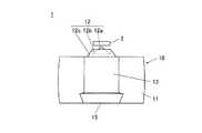
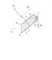
図1は、車両用灯具1の正面図である。図2は、車両用灯具1の平面図である。図3は、図1に図示のIII−IIIに沿った断面を矢印方向に見て示した断面図である。図4は、車両用灯具1の前側斜視図である。図5は、車両用灯具1の後ろ側斜視図である。なお、以下の説明において、「前」とは車両用灯具1から発する光束が進む向きであり、車両用灯具1の光軸Ax(図3に図示)が前後方向に延びている。  FIG. 1 is a front view of avehicular lamp 1. FIG. 2 is a plan view of thevehicular lamp 1. FIG. 3 is a cross-sectional view showing a cross section taken along the line III-III shown in FIG. FIG. 4 is a front perspective view of thevehicular lamp 1. FIG. 5 is a rear perspective view of thevehicular lamp 1. In the following description, “front” refers to the direction in which the light beam emitted from thevehicular lamp 1 travels, and the optical axis Ax (shown in FIG. 3) of thevehicular lamp 1 extends in the front-rear direction.

この車両用灯具1は、光源2及び導光体10を備える。光源2及び導光体10は、図示しないハウジング及び透光カバー(素通しのアウターレンズ)からなる灯室内に収容されている。  Thevehicle lamp 1 includes alight source 2 and alight guide 10. Thelight source 2 and thelight guide 10 are accommodated in a lamp chamber including a housing (not shown) and a translucent cover (a transparent outer lens).

光源2は基板上に実装されている。光源2が前方に向くように配置され、光源2の光軸Ax1が光源2から前方に延びている。光源2は前方に向けて放射状に光を発し、光源2の指向性が低い。光源2は、発光ダイオード、有機エレクトロルミネッセンス素子、無機エレクトロルミネッセンス素子その他の半導体発光素子である。  Thelight source 2 is mounted on the substrate. Thelight source 2 is disposed so as to face forward, and the optical axis Ax1 of thelight source 2 extends forward from thelight source 2. Thelight source 2 emits light radially toward the front, and the directivity of thelight source 2 is low. Thelight source 2 is a light emitting diode, an organic electroluminescent element, an inorganic electroluminescent element, or other semiconductor light emitting elements.

導光体10は、光源2の前方に配設されている。この導光体10は、光源2から発した光をコリメート状態にして取り込み、取り込まれた光を直交二方向に拡げるように2回内部反射させ、2回反射された光を光軸Ax方向に投射するものである。  Thelight guide 10 is disposed in front of thelight source 2. Thelight guide 10 captures the light emitted from thelight source 2 in a collimated state, internally reflects the captured light twice so as to spread it in two orthogonal directions, and reflects the reflected light twice in the optical axis Ax direction. Projected.

導光体10は、本体11、入射部12、第一反射面13、第二反射面14及び出射面15を有する。
本体11は透明な材料からなり、この本体11が光源2の前方に配設されている。
本体11の後面の上部には入射部12が形成され、本体11の前面の上部には第一反射面13が形成され、本体11の後面の下部には第二反射面14が形成され、本体11の前面の下部には出射面15が形成されている。なお、上下方向とは、車両用灯具1の光軸Ax及び光源2の光軸Ax1に沿う方向(前後方向)に直交する第一方向をいい、左右方向とは、車両用灯具1の光軸Ax及び光源2の光軸Ax1に沿う方向に直交するとともに、第一方向に直交する第二方向をいう。
Thelight guide 10 includes amain body 11, anincident portion 12, afirst reflection surface 13, asecond reflection surface 14, and anemission surface 15.
Themain body 11 is made of a transparent material, and themain body 11 is disposed in front of thelight source 2.
Anincident part 12 is formed at the upper part of the rear surface of themain body 11, a firstreflective surface 13 is formed at the upper part of the front surface of themain body 11, and a secondreflective surface 14 is formed at the lower part of the rear surface of themain body 11. Anemission surface 15 is formed at the lower part of the front surface of the 11. The vertical direction refers to a first direction orthogonal to a direction (front-rear direction) along the optical axis Ax of thevehicular lamp 1 and the optical axis Ax1 of thelight source 2, and the left-right direction refers to the optical axis of thevehicular lamp 1. Ax and the second direction perpendicular to the first direction and perpendicular to the direction along the optical axis Ax1 of thelight source 2 are referred to.

入射部12は光源2に対向する。この入射部12は、光源2から発した光を本体11の内部に取り込みつつ、光源2から発した光を略平行光に変換する。  Theincident part 12 faces thelight source 2. Theincident unit 12 converts the light emitted from thelight source 2 into substantially parallel light while taking the light emitted from thelight source 2 into themain body 11.

入射部12は、第一入射面12a、第二入射面12b及び反射面12cを有する。入射部12は、光源2の光軸Ax1を回転対称軸とする略円錐台状に形成されていて、本体11の後面から後方に突出するように設けられている。入射部12の頭部には凹部が形成されており、その凹部の奥には第一入射面12aが形成されており、その第一入射面12aが光源2に対向する。第一入射面12aは、光源2の光軸Ax1を回転対称軸とした回点対称な面であるとともに、光源2側へ膨出するよう凸面状に形成されている。第一入射面12aは、光源2から発した光を本体11の内部に取り込みつつ、その光を屈折によりコリメートする。第一入射面12aによってコリメートされた光は、光源2の光軸Ax1に略平行な平行光である。  Theincident portion 12 includes afirst incident surface 12a, asecond incident surface 12b, and a reflectingsurface 12c. Theincident portion 12 is formed in a substantially truncated cone shape having the optical axis Ax1 of thelight source 2 as a rotational symmetry axis, and is provided so as to protrude rearward from the rear surface of themain body 11. A concave portion is formed at the head of theincident portion 12, and afirst incident surface 12 a is formed at the back of the concave portion, and thefirst incident surface 12 a faces thelight source 2. Thefirst incident surface 12a is a point-symmetric surface with the optical axis Ax1 of thelight source 2 as a rotational symmetry axis, and is formed in a convex shape so as to bulge toward thelight source 2 side. Thefirst incident surface 12a collimates the light by refraction while taking the light emitted from thelight source 2 into themain body 11. The light collimated by thefirst incident surface 12a is parallel light substantially parallel to the optical axis Ax1 of thelight source 2.

入射部12の頭部に形成された凹部の内周面には、第二入射面12bが形成されており、第一入射面12aが第二入射面12bによって囲繞されている。第二入射面12bは、第一入射面12aの周縁部から後方に延びて、光源2の光軸Ax1を回転対称軸とした略円柱面状又は略円錐面状に形成されている。第二入射面12bは、光源2から発した光のうち第一入射面12aよりも側方へ向かう光を本体11の内部へ取り込む。  Asecond incident surface 12b is formed on the inner peripheral surface of the recess formed in the head of theincident portion 12, and thefirst incident surface 12a is surrounded by thesecond incident surface 12b. Thesecond incident surface 12b extends rearward from the peripheral portion of thefirst incident surface 12a and is formed in a substantially cylindrical surface shape or a substantially conical surface shape having the optical axis Ax1 of thelight source 2 as a rotational symmetry axis. Thesecond incident surface 12 b takes in light emitted from thelight source 2 toward the side of thefirst incident surface 12 a into themain body 11.

入射部12の外周面には、反射面12cが形成されている。反射面12cは、第二入射面12bの後ろ側の縁から前側に向かって外側(光源2の光軸Ax1から離間する側)へ広がるように傾斜して、第二入射面12bを囲繞する。反射面12cは、光源2の光軸Ax1を回転対称軸とした回点対称な裁頭円錐面状に設けられている。反射面12cは、第二入射面12bによって取り込まれた光を光源2の光軸Ax1に沿うように前へ内部反射させる。なお、反射面12cは、アルミ蒸着、銀蒸着等による反射膜が施された面であってもよいし、そのような反射膜が施されていない全反射面であってもよい。反射面12cに反射膜が形成されていれば、光の漏洩が防止される。  Areflection surface 12 c is formed on the outer peripheral surface of theincident portion 12. The reflectingsurface 12c is inclined so as to spread outward (side away from the optical axis Ax1 of the light source 2) from the rear edge of thesecond incident surface 12b toward the front, and surrounds thesecond incident surface 12b. Thereflection surface 12c is provided in a truncated cone shape having a point-of-turn symmetry with the optical axis Ax1 of thelight source 2 as a rotational symmetry axis. The reflectingsurface 12c internally reflects the light taken in by thesecond incident surface 12b forward along the optical axis Ax1 of thelight source 2. Thereflective surface 12c may be a surface provided with a reflective film by aluminum vapor deposition, silver vapor deposition, or the like, or may be a total reflection surface not provided with such a reflective film. If a reflective film is formed on thereflective surface 12c, light leakage is prevented.

第一入射面12bの面積を大きくとることができれば、第二入射面12b及び反射面12cを省略してもよい。第二入射面12b及び反射面12cがあることによって、第一入射面12bが小さくても、光源2を第一入射面12bの近くに配置することができ、光利用効率も向上する。  If the area of thefirst incident surface 12b can be increased, thesecond incident surface 12b and the reflectingsurface 12c may be omitted. By providing thesecond incident surface 12b and the reflectingsurface 12c, thelight source 2 can be disposed near thefirst incident surface 12b even if thefirst incident surface 12b is small, and the light utilization efficiency is improved.

第一反射面13は、入射部12の前方で入射部12に相対する位置にある。第一反射面13は、光源2の光軸Ax1に対して斜交いな軸線Ax2を中心軸としたシリンドリカル面状に形成されている。第一反射面13はシリンドリカル凹面であってもよいし、シリンドリカル凸面であってもよい。第一反射面13は、光源2の光軸Ax1に対して後ろ上がりに傾斜している。第一反射面13には、アルミ蒸着、銀蒸着等による反射膜が施されていてもよいし、そのような反射膜が施されていなくてもよい。第一反射面13は、入射部12によって取り込まれて本体11の内部を光軸Ax1に沿って前方に進む略平行光を、光軸Ax1方向に直交する第一方向(下方)へ内部反射させつつ、その反射光を、前後方向及び第一方向に直交する第二方向(左右方向)に拡散させる。  The first reflectingsurface 13 is in a position facing theincident part 12 in front of theincident part 12. The first reflectingsurface 13 is formed in a cylindrical surface shape having an axis Ax2 oblique to the optical axis Ax1 of thelight source 2 as a central axis. The first reflectingsurface 13 may be a cylindrical concave surface or a cylindrical convex surface. The first reflectingsurface 13 is inclined backward and upward with respect to the optical axis Ax1 of thelight source 2. The firstreflective surface 13 may be provided with a reflective film by aluminum vapor deposition, silver vapor deposition, or the like, or may not be provided with such a reflective film. The first reflectingsurface 13 internally reflects substantially parallel light that is taken in by theincident portion 12 and travels forward in themain body 11 along the optical axis Ax1 in a first direction (downward) orthogonal to the optical axis Ax1 direction. Meanwhile, the reflected light is diffused in the second direction (left-right direction) orthogonal to the front-rear direction and the first direction.

第二反射面14は第一反射面13の下方にあり、第二反射面14と入射部12が上下にずれている。第二反射面14は、左右方向に沿った軸線Ax3を中心軸としたシリンドリカル面状に形成されている。具体的には、本体11の外部から見た場合、第二反射面14がシリンドリカル凸面であり、本体11の内部から見た場合、第二反射面14がシリンドリカル凹面である。第二反射面14には、アルミ蒸着、銀蒸着等による反射膜が施されていてもよいし、そのような反射膜が施されていなくてもよい。第二反射面14は、第一反射面13によって反射されて本体11の内部を下方に進む光を、光軸Ax1の方向に略平行な方向へ内部反射させつつ、その反射光を、第一方向(上下方向)に拡散させる。  The second reflectingsurface 14 is below the first reflectingsurface 13, and the second reflectingsurface 14 and theincident portion 12 are shifted up and down. The second reflectingsurface 14 is formed in a cylindrical surface shape with the axis Ax3 along the left-right direction as the central axis. Specifically, when viewed from the outside of themain body 11, the second reflectingsurface 14 is a cylindrical convex surface, and when viewed from the inside of themain body 11, the second reflectingsurface 14 is a cylindrical concave surface. The secondreflective surface 14 may be provided with a reflective film by aluminum vapor deposition, silver vapor deposition, or the like, or may not be provided with such a reflective film. The second reflectingsurface 14 reflects light reflected by the first reflectingsurface 13 and traveling downward in themain body 11 in a direction substantially parallel to the direction of the optical axis Ax1, while reflecting the reflected light to the first reflectingsurface 13. Spread in the direction (vertical direction).

出射面15は第二反射面14の前方にあり、出射面15と第一反射面13が上下にずれている。出射面15は、段差及び切り込みが無い面であり、好ましくは車両用灯具1の光軸Ax及び光源2の光軸Ax1に対して垂直な平坦面である。この出射面15は、第二反射面14によって反射されて本体11の内部を前方(第一方向)に進む光を本体11から出射させる。  Theexit surface 15 is in front of the second reflectingsurface 14, and theexit surface 15 and the first reflectingsurface 13 are shifted up and down. Theexit surface 15 is a surface without a step and a cut, and is preferably a flat surface perpendicular to the optical axis Ax of thevehicular lamp 1 and the optical axis Ax1 of thelight source 2. Theemission surface 15 emits light from themain body 11 that is reflected by thesecond reflection surface 14 and travels forward (first direction) through the inside of themain body 11.

出射面15が平坦面ではなく、凸面又は凹面であってもよい。出射面15が凸面又は凹面である場合でも、出射面15に段差及び切り込みが無いことが好ましい。なお、出射面15は、平坦面、凸面又は凹面に僅かなレンズカット又はシボが形成されたものでもよい。  Theexit surface 15 may be a convex surface or a concave surface instead of a flat surface. Even when theexit surface 15 is a convex surface or a concave surface, it is preferable that theexit surface 15 has no step and notch. Theexit surface 15 may be a flat surface, convex surface, or concave surface with a slight lens cut or texture.

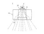
図6、図7は、光源2から発した光線の軌跡を示す図である。図6、図7に示すように、光源2から第一入射面12aに進行する光が第一入射面12aに入射し、その入射光が第一入射面12aの屈折により光軸Ax1に平行な略平行光に変換される。また、光源2から第二入射面12bに進行する光が第二入射面12bに入射し、その入射光は反射面12cによって光軸Ax1方向へ内部反射されつつ、反射面12cによって光軸Ax1に平行な略平行光に変換される。本体11の内部を入射部12から第一反射面13に進行する略平行光は、第一反射面13によって下方へ内部反射されつつ、第一反射面13によって左右方向に拡散される。本体11の内部を第一反射面13から第二反射面14に進行する光は、第二反射面14によって前方へ内部反射されつつ、第二反射面14によって上下方向に拡散される。本体11の内部を第二反射面14から出射面15に進行する光は、出射面15から前方に出射される。  6 and 7 are diagrams showing the locus of light rays emitted from thelight source 2. As shown in FIGS. 6 and 7, light traveling from thelight source 2 to thefirst incident surface 12a is incident on thefirst incident surface 12a, and the incident light is parallel to the optical axis Ax1 due to refraction of thefirst incident surface 12a. It is converted into substantially parallel light. Further, light traveling from thelight source 2 to thesecond incident surface 12b is incident on thesecond incident surface 12b, and the incident light is internally reflected in the direction of the optical axis Ax1 by the reflectingsurface 12c, while being reflected on the optical axis Ax1 by the reflectingsurface 12c. It is converted into parallel substantially parallel light. The substantially parallel light traveling inside themain body 11 from theincident portion 12 to the first reflectingsurface 13 is diffused in the left-right direction by the first reflectingsurface 13 while being internally reflected downward by the first reflectingsurface 13. Light traveling in themain body 11 from the first reflectingsurface 13 to the second reflectingsurface 14 is diffused in the vertical direction by the second reflectingsurface 14 while being internally reflected forward by the second reflectingsurface 14. The light traveling from the second reflectingsurface 14 to theemission surface 15 in themain body 11 is emitted forward from theemission surface 15.

以上のような車両用灯具1は、以下のような効果をもたらす。  Thevehicular lamp 1 as described above has the following effects.

(1) 光源2から発した光が第一反射面13によって左右方向に拡げられ、更にその光が第二反射面14によって上下方向に拡げられるから、上下左右に拡がった配光を得ることができる。(1) Since the light emitted from thelight source 2 is expanded in the left-right direction by the first reflectingsurface 13, and the light is further expanded in the up-down direction by the second reflectingsurface 14, it is possible to obtain a light distribution spreading in the upper, lower, left and right directions. it can.

(2) 第一反射面13、第二反射面14によって上下左右に拡がった配光が得られるから、出射面15の光学的設計の自由度が向上する。そのため、車両用灯具1の意匠設計の自由度が向上する。(2) Since the first and second reflectingsurfaces 13 and 14 can provide a light distribution that expands vertically and horizontally, the degree of freedom in optical design of theexit surface 15 is improved. Therefore, the freedom degree of the design design of thevehicle lamp 1 is improved.

(3) 第一反射面13及び第二反射面14によって配光が形成されるから、出射面15にレンズ素子を形成しなくても済み、出射面15を段差及び切り込みの無い面とすることができる。そのため、車両用灯具1の意匠性が高く、その車両用灯具1の意匠面(出射面15)の凹凸感やカットラインがなく、その意匠面で点光りも発生せず、更に非点灯時の見栄えもよい。(3) Since the light distribution is formed by the first reflectingsurface 13 and the second reflectingsurface 14, it is not necessary to form a lens element on theexit surface 15, and theexit surface 15 is a surface having no steps and notches. Can do. Therefore, the design property of thevehicular lamp 1 is high, there is no unevenness or cut line on the design surface (outgoing surface 15) of thevehicular lamp 1, no flashing occurs on the design surface, and further when the lamp is not lit It looks good.

(4) 光源2から発した光が入射部12によって平行光になるから、第一反射面13及び第二反射面14の光学的設計を行いやすい。(4) Since the light emitted from thelight source 2 becomes parallel light by theincident portion 12, the firstreflective surface 13 and the secondreflective surface 14 can be easily optically designed.

(5) 光源2が出射面15に映りにくいので、出射面15を見ても光源2を視認しにくい。そのため、見栄えが向上する。(5) Since thelight source 2 is not easily reflected on theemission surface 15, it is difficult to visually recognize thelight source 2 even when theemission surface 15 is viewed. Therefore, the appearance is improved.

(6) 導光体10は、光を二回反射させる単純な構造である。そのため、光が損失しにくい。特に、第一反射面13や第二反射面14に反射膜がコーティングされていれば、光の損失を更に抑えることができる。(6) Thelight guide 10 has a simple structure that reflects light twice. Therefore, it is difficult to lose light. In particular, if the firstreflective surface 13 and the secondreflective surface 14 are coated with a reflective film, light loss can be further suppressed.

〔応用例1〕
図8は、車両用のライン状ランプの斜視図である。図8に示すように、複数の導光体10が左右方向(第二方向)に一列に配列され、複数の光源2(図8では、導光体10の裏側に隠れている)が左右方向に一列に配列されている。これら導光体10が一体成形されており、何れの導光体10も出射面15が前に向いている。出射面15が平坦面であれば、これら出射面15が面一になっている。
[Application Example 1]
FIG. 8 is a perspective view of a line lamp for a vehicle. As shown in FIG. 8, the plurality of light guides 10 are arranged in a line in the left-right direction (second direction), and the plurality of light sources 2 (hidden on the back side of the
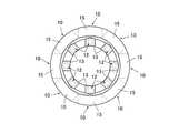
light guide 10 in FIG. 8) are in the left-right direction. Are arranged in a row. These light guides 10 are integrally formed, and anylight guide 10 has theemission surface 15 facing forward. If theemission surface 15 is a flat surface, theseemission surfaces 15 are flush with each other.

〔応用例2〕
図9は、車両用の丸目ランプの正面図である。図9に示すように、入射部12及び第一反射面13が第二反射面14及び出射面15よりも中心寄りになるように複数の導光体10が環状に配列され、複数の光源2(図9では、導光体10の裏側に隠れている)が環状に配列されている。これら導光体10が一体成形されており、何れの導光体10も出射面15が前に向いている。出射面15が平坦面であれば、これら出射面15が面一になっている。
[Application 2]
FIG. 9 is a front view of a round lamp for a vehicle. As shown in FIG. 9, the plurality of light guides 10 are arranged in an annular shape so that the
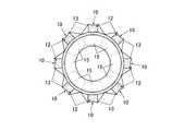
incident portion 12 and thefirst reflection surface 13 are closer to the center than thesecond reflection surface 14 and theemission surface 15, and the plurality oflight sources 2. (In FIG. 9, they are hidden behind the light guide 10) are arranged in an annular shape. These light guides 10 are integrally formed, and anylight guide 10 has theemission surface 15 facing forward. If theemission surface 15 is a flat surface, theseemission surfaces 15 are flush with each other.

〔応用例3〕
図10、図11は、車両用の丸目ランプの正面図である。図10、図11に示すように、第二反射面14及び出射面15が入射部12及び第一反射面13よりも中心寄りになるように複数の導光体10が環状に配列され、複数の光源2が環状に配列されている。これら導光体10が一体成形されており、何れの導光体10も出射面15が前に向いている。出射面15が平坦面であれば、これら出射面15が面一になっている。
[Application Example 3]
10 and 11 are front views of a round lamp for a vehicle. As shown in FIGS. 10 and 11, the plurality of light guides 10 are annularly arranged so that thesecond reflection surface 14 and theemission surface 15 are closer to the center than theincident portion 12 and thefirst reflection surface 13. Are arranged in a ring shape. These light guides 10 are integrally formed, and anylight guide 10 has theemission surface 15 facing forward. If theemission surface 15 is a flat surface, theseemission surfaces 15 are flush with each other.

本発明に係る車両用灯具は、前照灯、補助前照灯、信号灯、方向指示灯、車幅灯、尾灯、制動灯、補助制動灯、室内灯、コンビネーションランプ、ドアミラーターンランプ、トランクリッドランプその他の車両用灯具に適用可能である。  The vehicular lamp according to the present invention includes a headlamp, an auxiliary headlamp, a signal lamp, a direction indicator lamp, a vehicle width lamp, a tail lamp, a brake lamp, an auxiliary brake lamp, an interior lamp, a combination lamp, a door mirror turn lamp, and a trunk lid lamp. It can be applied to other vehicle lamps.

1 車両用灯具
2 光源
10 導光体
11 本体
12 入射部
13 第一反射面
14 第二反射面
15 出射面
Ax 灯具の光軸
Ax1 光源の光軸
DESCRIPTION OFSYMBOLS 1Vehicle lamp 2Light source 10Light guide 11Main body 12Incident part 13 Firstreflective surface 14 Secondreflective surface 15 Outgoing surface Ax Optical axis of lamp Ax1 Optical axis of light source

Claims (4)

Translated fromJapanese
導光体と、
前方を向く光軸を有する光源と、を備え、
前記導光体は、
前記光源の前方に配設された透明な本体と、
前記光源に対向する位置であって前記本体の後面に形成され、前記光源から発した光を前記本体の内部に取り込む入射部と、
前記入射部に相対する位置であって前記本体の前面に形成され、前記入射部によって前記本体の内部に取り込まれた光を前記光軸の方向に直交する第一方向へ反射させつつ、その光を前記光軸の方向及び前記第一方向に直交する第二方向に拡散させる第一反射面と、
前記入射部から前記第一方向にずれた位置であって前記本体の後面に形成され、前記第一反射面によって反射された光を前記光軸の方向へ反射させつつ、その光を前記第一方向に拡散させる第二反射面と、
前記第一反射面から前記第一方向にずれた位置であって前記本体の前面に形成され、前記第二反射面で反射された光を前記本体の内部から出射させる出射面と、を有することを特徴とする車両用灯具。
A light guide;
A light source having an optical axis facing forward,
The light guide is
A transparent body disposed in front of the light source;
An incident portion that is formed on the rear surface of the main body at a position facing the light source, and takes in light emitted from the light source into the main body.
The light that is formed at the front surface of the main body at a position opposite to the incident portion and reflected by the incident portion into the main body in a first direction orthogonal to the direction of the optical axis, A first reflecting surface that diffuses in a direction perpendicular to the direction of the optical axis and the first direction;
The light that is formed on the rear surface of the main body at a position shifted in the first direction from the incident portion and reflected by the first reflecting surface is reflected in the direction of the optical axis, and the light is reflected in the first direction. A second reflecting surface that diffuses in the direction;
An exit surface formed on the front surface of the main body at a position shifted in the first direction from the first reflective surface and configured to emit light reflected from the second reflective surface from the inside of the main body. A vehicular lamp characterized by the above.
前記出射面が、段差及び切り込みの無い平坦面状、凸面状又は凹面状に形成されていることを特徴とする請求項1に記載の車両用灯具。  2. The vehicular lamp according to claim 1, wherein the emission surface is formed in a flat surface shape, a convex surface shape, or a concave surface shape without a step and a cut. 前記第一反射面が、前記光軸に対して斜交いな軸線を中心軸としたシリンドリカル面状に形成されていることを特徴とする請求項1又は2に記載の車両用灯具。  3. The vehicular lamp according to claim 1, wherein the first reflecting surface is formed in a cylindrical surface shape with an axis line oblique to the optical axis as a central axis. 4. 前記第二反射面が、前記第二方向に沿った軸線を中心軸としたシリンドリカル面状に、且つ前記本体の外部から見て凸面状に形成されていることを特徴とする請求項1から3の何れか一項に記載の車両用灯具。  The second reflection surface is formed in a cylindrical surface shape having an axis along the second direction as a central axis and a convex shape when viewed from the outside of the main body. The vehicle lamp according to any one of the above.
JP2011252230A2011-11-182011-11-18 Vehicle lightingActiveJP5801164B2 (en)

Priority Applications (1)

Application NumberPriority DateFiling DateTitle
JP2011252230AJP5801164B2 (en)2011-11-182011-11-18 Vehicle lighting

Applications Claiming Priority (1)

Application NumberPriority DateFiling DateTitle
JP2011252230AJP5801164B2 (en)2011-11-182011-11-18 Vehicle lighting

Publications (2)

Publication NumberPublication Date
JP2013109871A JP2013109871A (en)2013-06-06
JP5801164B2true JP5801164B2 (en)2015-10-28

Family

ID=48706462

Family Applications (1)

Application NumberTitlePriority DateFiling Date
JP2011252230AActiveJP5801164B2 (en)2011-11-182011-11-18 Vehicle lighting

Country Status (1)

CountryLink
JP (1)JP5801164B2 (en)

Families Citing this family (6)

* Cited by examiner, † Cited by third party
Publication numberPriority datePublication dateAssigneeTitle
JP6245959B2 (en)*2013-11-222017-12-13スタンレー電気株式会社 Lamp
JP6201708B2 (en)*2013-12-112017-09-27スタンレー電気株式会社 Vehicle lamp and lens body
JP6459252B2 (en)*2014-07-032019-01-30市光工業株式会社 Vehicle lighting
CN110067985B (en)2014-07-082021-09-10三菱电机株式会社Headlight module
KR102470446B1 (en)*2017-12-282022-11-24에스엘 주식회사Lamp for vehicle
JP7424169B2 (en)2020-03-312024-01-30市光工業株式会社 Vehicle light guide and vehicle lighting unit

Family Cites Families (2)

* Cited by examiner, † Cited by third party
Publication numberPriority datePublication dateAssigneeTitle
JP4113111B2 (en)*2003-12-242008-07-09株式会社小糸製作所 VEHICLE LIGHT UNIT AND VEHICLE LIGHTING LIGHT
JP4468857B2 (en)*2005-05-172010-05-26株式会社小糸製作所 Lighting fixtures for vehicles

Also Published As

Publication numberPublication date
JP2013109871A (en)2013-06-06

Similar Documents

PublicationPublication DateTitle
JP5945857B2 (en) Vehicle headlamp and light guide lens
JP5518559B2 (en) Lamp unit
JP5801164B2 (en) Vehicle lighting
JP2012243493A (en)Vehicular signal lamp
JP5814302B2 (en) Vehicle lamp
JP6560514B2 (en) Vehicle lighting
JP2017212037A (en)Vehicular headlight
JP5397186B2 (en) Vehicle lighting
JP2017084581A (en)Light distribution optical system and vehicular lighting tool
JP2021197354A (en) Automotive lamps and automobiles including those lamps
JP5387897B2 (en) Vehicle lighting
JP5255947B2 (en) Vehicle lamp
JP2014154524A (en)Lighting fixture
JP2015153577A (en) Vehicle lighting
JP2017112037A (en) Vehicle lighting
JP6737644B2 (en) Vehicle lighting
JP2008147003A (en) Vehicle headlamp lamp unit
JP6383583B2 (en) Vehicle lighting device
JP6221438B2 (en) Vehicle lighting
JP4493610B2 (en) Vehicle lamp
JP6518459B2 (en) Vehicle lamp
JP6035901B2 (en) Vehicle lighting
JP2013168269A (en)Vehicular lamp
JP2013045718A (en)Vehicle lighting fixture
JP6215415B2 (en) Vehicle lighting

Legal Events

DateCodeTitleDescription
A621Written request for application examination

Free format text:JAPANESE INTERMEDIATE CODE: A621

Effective date:20141107

TRDDDecision of grant or rejection written
A977Report on retrieval

Free format text:JAPANESE INTERMEDIATE CODE: A971007

Effective date:20150722

A01Written decision to grant a patent or to grant a registration (utility model)

Free format text:JAPANESE INTERMEDIATE CODE: A01

Effective date:20150728

A61First payment of annual fees (during grant procedure)

Free format text:JAPANESE INTERMEDIATE CODE: A61

Effective date:20150826

R150Certificate of patent or registration of utility model

Ref document number:5801164

Country of ref document:JP

Free format text:JAPANESE INTERMEDIATE CODE: R150

R250Receipt of annual fees

Free format text:JAPANESE INTERMEDIATE CODE: R250

R250Receipt of annual fees

Free format text:JAPANESE INTERMEDIATE CODE: R250

R250Receipt of annual fees

Free format text:JAPANESE INTERMEDIATE CODE: R250

R250Receipt of annual fees

Free format text:JAPANESE INTERMEDIATE CODE: R250

R250Receipt of annual fees

Free format text:JAPANESE INTERMEDIATE CODE: R250

R250Receipt of annual fees

Free format text:JAPANESE INTERMEDIATE CODE: R250

R250Receipt of annual fees

Free format text:JAPANESE INTERMEDIATE CODE: R250

R250Receipt of annual fees

Free format text:JAPANESE INTERMEDIATE CODE: R250


[8]ページ先頭

©2009-2025 Movatter.jp