JP5799488B2 - Intravascular drug elution catheter - Google Patents
Intravascular drug elution catheterDownload PDFInfo
- Publication number
- JP5799488B2 JP5799488B2JP2010165553AJP2010165553AJP5799488B2JP 5799488 B2JP5799488 B2JP 5799488B2JP 2010165553 AJP2010165553 AJP 2010165553AJP 2010165553 AJP2010165553 AJP 2010165553AJP 5799488 B2JP5799488 B2JP 5799488B2
- Authority
- JP
- Japan
- Prior art keywords
- drug
- wire
- catheter
- elastic deformation
- shaft
- Prior art date
- Legal status (The legal status is an assumption and is not a legal conclusion. Google has not performed a legal analysis and makes no representation as to the accuracy of the status listed.)
- Active
Links
- 239000003814drugSubstances0.000titleclaimsdescription110
- 229940079593drugDrugs0.000titleclaimsdescription101
- 238000010828elutionMethods0.000titledescription14
- 230000005489elastic deformationEffects0.000claimsdescription60
- 239000012528membraneSubstances0.000claimsdescription4
- 210000004204blood vesselAnatomy0.000description45
- 208000031481Pathologic ConstrictionDiseases0.000description10
- 208000037804stenosisDiseases0.000description10
- 230000036262stenosisEffects0.000description10
- 239000008280bloodSubstances0.000description8
- 210000004369bloodAnatomy0.000description8
- 230000017531blood circulationEffects0.000description7
- 238000003780insertionMethods0.000description5
- 230000037431insertionEffects0.000description5
- 239000000463materialSubstances0.000description5
- -1polypropylenePolymers0.000description5
- 238000012986modificationMethods0.000description4
- 230000004048modificationEffects0.000description4
- 230000002093peripheral effectEffects0.000description4
- 239000004743PolypropyleneSubstances0.000description3
- 229910045601alloyInorganic materials0.000description3
- 239000000956alloySubstances0.000description3
- 230000000903blocking effectEffects0.000description3
- 230000008602contractionEffects0.000description3
- 210000004351coronary vesselAnatomy0.000description3
- 238000010586diagramMethods0.000description3
- 238000000034methodMethods0.000description3
- 229920001155polypropylenePolymers0.000description3
- 239000011347resinSubstances0.000description3
- 229920005989resinPolymers0.000description3
- 208000037803restenosisDiseases0.000description3
- 229910001220stainless steelInorganic materials0.000description3
- 239000004952PolyamideSubstances0.000description2
- QZPQTZZNNJUOLS-UHFFFAOYSA-Nbeta-lapachoneChemical compoundC12=CC=CC=C2C(=O)C(=O)C2=C1OC(C)(C)CC2QZPQTZZNNJUOLS-UHFFFAOYSA-N0.000description2
- 238000007887coronary angioplastyMethods0.000description2
- 230000000694effectsEffects0.000description2
- 239000010410layerSubstances0.000description2
- 229920002647polyamidePolymers0.000description2
- 229910017535Cu-Al-NiInorganic materials0.000description1
- 229910017773Cu-Zn-AlInorganic materials0.000description1
- YCKRFDGAMUMZLT-UHFFFAOYSA-NFluorine atomChemical compound[F]YCKRFDGAMUMZLT-UHFFFAOYSA-N0.000description1
- 239000002033PVDF binderSubstances0.000description1
- 229930012538PaclitaxelNatural products0.000description1
- 229920002614Polyether block amidePolymers0.000description1
- 239000004698PolyethyleneSubstances0.000description1
- 229930003316Vitamin DNatural products0.000description1
- QYSXJUFSXHHAJI-XFEUOLMDSA-NVitamin D3Natural productsC1(/[C@@H]2CC[C@@H]([C@]2(CCC1)C)[C@H](C)CCCC(C)C)=C/C=C1\C[C@@H](O)CCC1=CQYSXJUFSXHHAJI-XFEUOLMDSA-N0.000description1
- 239000000654additiveSubstances0.000description1
- 230000000996additive effectEffects0.000description1
- 238000013459approachMethods0.000description1
- 239000003795chemical substances by applicationSubstances0.000description1
- 239000011248coating agentSubstances0.000description1
- 238000000576coating methodMethods0.000description1
- 230000000916dilatatory effectEffects0.000description1
- 230000002708enhancing effectEffects0.000description1
- 229910052731fluorineInorganic materials0.000description1
- 239000011737fluorineSubstances0.000description1
- 239000011497hempcreteSubstances0.000description1
- KHYBPSFKEHXSLX-UHFFFAOYSA-NiminotitaniumChemical compound[Ti]=NKHYBPSFKEHXSLX-UHFFFAOYSA-N0.000description1
- 208000010125myocardial infarctionDiseases0.000description1
- 229910001000nickel titaniumInorganic materials0.000description1
- 229960001592paclitaxelDrugs0.000description1
- 230000000149penetrating effectEffects0.000description1
- 239000012466permeateSubstances0.000description1
- 239000004033plasticSubstances0.000description1
- 229920003023plasticPolymers0.000description1
- 229920000728polyesterPolymers0.000description1
- 229920000573polyethylenePolymers0.000description1
- 229920001343polytetrafluoroethylenePolymers0.000description1
- 239000004810polytetrafluoroethyleneSubstances0.000description1
- 229920002981polyvinylidene fluoridePolymers0.000description1
- 239000011241protective layerSubstances0.000description1
- ZAHRKKWIAAJSAO-UHFFFAOYSA-NrapamycinNatural productsCOCC(O)C(=C/C(C)C(=O)CC(OC(=O)C1CCCCN1C(=O)C(=O)C2(O)OC(CC(OC)C(=CC=CC=CC(C)CC(C)C(=O)C)C)CCC2C)C(C)CC3CCC(O)C(C3)OC)CZAHRKKWIAAJSAO-UHFFFAOYSA-N0.000description1
- 238000000926separation methodMethods0.000description1
- 229910001285shape-memory alloyInorganic materials0.000description1
- QFJCIRLUMZQUOT-HPLJOQBZSA-NsirolimusChemical compoundC1C[C@@H](O)[C@H](OC)C[C@@H]1C[C@@H](C)[C@H]1OC(=O)[C@@H]2CCCCN2C(=O)C(=O)[C@](O)(O2)[C@H](C)CC[C@H]2C[C@H](OC)/C(C)=C/C=C/C=C/[C@@H](C)C[C@@H](C)C(=O)[C@H](OC)[C@H](O)/C(C)=C/[C@@H](C)C(=O)C1QFJCIRLUMZQUOT-HPLJOQBZSA-N0.000description1
- 229960002930sirolimusDrugs0.000description1
- 239000010935stainless steelSubstances0.000description1
- 230000002966stenotic effectEffects0.000description1
- 239000000126substanceSubstances0.000description1
- RCINICONZNJXQF-MZXODVADSA-NtaxolChemical compoundO([C@@H]1[C@@]2(C[C@@H](C(C)=C(C2(C)C)[C@H](C([C@]2(C)[C@@H](O)C[C@H]3OC[C@]3([C@H]21)OC(C)=O)=O)OC(=O)C)OC(=O)[C@H](O)[C@@H](NC(=O)C=1C=CC=CC=1)C=1C=CC=CC=1)O)C(=O)C1=CC=CC=C1RCINICONZNJXQF-MZXODVADSA-N0.000description1
- 230000000451tissue damageEffects0.000description1
- 231100000827tissue damageToxicity0.000description1
- 235000019166vitamin DNutrition0.000description1
- 239000011710vitamin DSubstances0.000description1
- 150000003710vitamin D derivativesChemical class0.000description1
- 229940046008vitamin dDrugs0.000description1
Images


Classifications
- A—HUMAN NECESSITIES
- A61—MEDICAL OR VETERINARY SCIENCE; HYGIENE
- A61M—DEVICES FOR INTRODUCING MEDIA INTO, OR ONTO, THE BODY; DEVICES FOR TRANSDUCING BODY MEDIA OR FOR TAKING MEDIA FROM THE BODY; DEVICES FOR PRODUCING OR ENDING SLEEP OR STUPOR
- A61M29/00—Dilators with or without means for introducing media, e.g. remedies
- A61M29/02—Dilators made of swellable material
- A—HUMAN NECESSITIES
- A61—MEDICAL OR VETERINARY SCIENCE; HYGIENE
- A61M—DEVICES FOR INTRODUCING MEDIA INTO, OR ONTO, THE BODY; DEVICES FOR TRANSDUCING BODY MEDIA OR FOR TAKING MEDIA FROM THE BODY; DEVICES FOR PRODUCING OR ENDING SLEEP OR STUPOR
- A61M25/00—Catheters; Hollow probes
- A61M25/10—Balloon catheters
- A61M25/104—Balloon catheters used for angioplasty
- A—HUMAN NECESSITIES
- A61—MEDICAL OR VETERINARY SCIENCE; HYGIENE
- A61M—DEVICES FOR INTRODUCING MEDIA INTO, OR ONTO, THE BODY; DEVICES FOR TRANSDUCING BODY MEDIA OR FOR TAKING MEDIA FROM THE BODY; DEVICES FOR PRODUCING OR ENDING SLEEP OR STUPOR
- A61M25/00—Catheters; Hollow probes
- A61M25/0067—Catheters; Hollow probes characterised by the distal end, e.g. tips
- A61M25/0074—Dynamic characteristics of the catheter tip, e.g. openable, closable, expandable or deformable
- A—HUMAN NECESSITIES
- A61—MEDICAL OR VETERINARY SCIENCE; HYGIENE
- A61M—DEVICES FOR INTRODUCING MEDIA INTO, OR ONTO, THE BODY; DEVICES FOR TRANSDUCING BODY MEDIA OR FOR TAKING MEDIA FROM THE BODY; DEVICES FOR PRODUCING OR ENDING SLEEP OR STUPOR
- A61M25/00—Catheters; Hollow probes
- A61M25/0043—Catheters; Hollow probes characterised by structural features
- A61M2025/0057—Catheters delivering medicament other than through a conventional lumen, e.g. porous walls or hydrogel coatings
- A—HUMAN NECESSITIES
- A61—MEDICAL OR VETERINARY SCIENCE; HYGIENE
- A61M—DEVICES FOR INTRODUCING MEDIA INTO, OR ONTO, THE BODY; DEVICES FOR TRANSDUCING BODY MEDIA OR FOR TAKING MEDIA FROM THE BODY; DEVICES FOR PRODUCING OR ENDING SLEEP OR STUPOR
- A61M25/00—Catheters; Hollow probes
- A61M25/01—Introducing, guiding, advancing, emplacing or holding catheters
- A61M25/06—Body-piercing guide needles or the like
- A61M25/0662—Guide tubes
- A61M2025/0681—Systems with catheter and outer tubing, e.g. sheath, sleeve or guide tube
- A—HUMAN NECESSITIES
- A61—MEDICAL OR VETERINARY SCIENCE; HYGIENE
- A61M—DEVICES FOR INTRODUCING MEDIA INTO, OR ONTO, THE BODY; DEVICES FOR TRANSDUCING BODY MEDIA OR FOR TAKING MEDIA FROM THE BODY; DEVICES FOR PRODUCING OR ENDING SLEEP OR STUPOR
- A61M25/00—Catheters; Hollow probes
- A61M25/0021—Catheters; Hollow probes characterised by the form of the tubing
- A61M25/0023—Catheters; Hollow probes characterised by the form of the tubing by the form of the lumen, e.g. cross-section, variable diameter
- A61M25/0026—Multi-lumen catheters with stationary elements
- A61M25/003—Multi-lumen catheters with stationary elements characterized by features relating to least one lumen located at the distal part of the catheter, e.g. filters, plugs or valves
Landscapes
- Health & Medical Sciences (AREA)
- Life Sciences & Earth Sciences (AREA)
- Heart & Thoracic Surgery (AREA)
- Hematology (AREA)
- Engineering & Computer Science (AREA)
- Anesthesiology (AREA)
- Biomedical Technology (AREA)
- Animal Behavior & Ethology (AREA)
- General Health & Medical Sciences (AREA)
- Public Health (AREA)
- Veterinary Medicine (AREA)
- Vascular Medicine (AREA)
- Pulmonology (AREA)
- Biophysics (AREA)
- Child & Adolescent Psychology (AREA)
- Media Introduction/Drainage Providing Device (AREA)
Description
Translated fromJapanese本発明は、血管内において薬剤を溶出することができるカテーテルに関する。 The present invention relates to a catheter capable of eluting a drug in a blood vessel.
従来より、血管にカテーテルを挿入して薬剤を局所的に投与する治療が行われている。例えば、冠動脈形成術(PTCA)において冠動脈の狭窄部分をバルーンカテーテルで拡張し、その後に冠動脈の再狭窄を防止するために薬剤が血管壁に浸透される。薬剤を血管壁に浸透させる器具として、バルーンに薬剤を含浸させたバルーンカテーテルが知られている(特許文献1,2)。 Conventionally, a treatment in which a drug is locally administered by inserting a catheter into a blood vessel has been performed. For example, in coronary angioplasty (PTCA), a stenotic portion of the coronary artery is expanded with a balloon catheter, and then a drug is infiltrated into the blood vessel wall to prevent restenosis of the coronary artery. A balloon catheter in which a balloon is impregnated with a drug is known as a device for penetrating the drug into the blood vessel wall (Patent Documents 1 and 2).
前述されたようなバルーンカテーテルを用いた施術においては、薬剤を浸透させるべき血管壁までバルーンカテーテルを挿入してバルーンを拡張し、拡張されたバルーンを血管壁に数分間圧迫させることによって、バルーンに含浸されている薬剤を溶出させて血管壁へ浸透させる。しかしながら、拡張されたバルーンによって、バルーンより末梢側への血流を遮断することは、心筋壊死などの組織障害を誘発するおそれがあるので好ましくない。一方、バルーンを拡張した状態に維持する時間を短くすると、血管壁に十分な量の薬剤を浸透させることができない。 In the operation using the balloon catheter as described above, the balloon is expanded by inserting the balloon catheter up to the blood vessel wall to be infiltrated with the drug, and the expanded balloon is compressed against the blood vessel wall for several minutes. The impregnated drug is eluted and penetrates into the blood vessel wall. However, blocking the blood flow to the peripheral side of the balloon with the expanded balloon is not preferable because it may induce tissue damage such as myocardial necrosis. On the other hand, if the time for maintaining the balloon in an expanded state is shortened, a sufficient amount of drug cannot penetrate into the blood vessel wall.
本発明は、このような事情に鑑みてなされたものであり、その目的は、末梢側への血流を遮断することなく血管壁に直接に薬剤を浸透させることができる手段を提供することにある。 This invention is made | formed in view of such a situation, The objective is to provide the means which can osmose | permeate a chemical | medical agent directly to the blood vessel wall, without interrupting the blood flow to a peripheral side. is there.
(1) 本発明に係る血管内薬剤溶出カテーテルは、複数の線材が周方向に離間されて配置されており、各線材が離間されて長尺方向の中央部分の外径が拡がった籠形状の拡張姿勢を維持し、各線材が近接して当該中央部分の外径が縮んだ収縮姿勢に弾性的に変形する弾性変形部と、上記弾性変形部が先端側に設けられたシャフトと、上記収縮姿勢の上記弾性変形部及び上記シャフトが挿通可能な第1ルーメンを有するカテーテル本体と、上記弾性変形部の中央部分においてのみ上記拡張姿勢における各線材に対して周方向へ張り渡されており、上記弾性変形部の姿勢変化に追従する可撓性を有し、薬剤の保持及び溶出が可能な薬剤保持膜と、上記薬剤保持膜に保持された薬剤と、を具備する。上記弾性変形部は、上記各線材が上記長尺方向に対して螺旋をなして延出されており、当該各線材の両端が結束されて上記中央部分が最大径とされており、当該中央部分において当該各線材が交差していない。(1) intravascular drug eluting catheter of the present invention is arranged a plurality of wiresis circumferentially spaced, wire members of basket shape having an outer diameter spread of the central portion of the spaced by the longitudinal direction An elastically deformable portion that maintains an expanded posture and elastically deforms into a contracted posture in which the outer diameter of the central portion is reduced as each wire rod approaches, a shaft provided with the elastically deformable portion on the distal end side, and the contraction The catheter body having a first lumen through which the elastically deforming portion and the shaft can be inserted, and the wire portions in the expanded posture are stretched in the circumferential direction only at the central portion of the elastically deforming portion, A drug holding film that has flexibility to follow a change in posture of the elastically deformable portion and can hold and dissolve the drug, and a drug held on the drug holding film.The elastically deforming portion is formed by extending each wire rod in a spiral with respect to the longitudinal direction, binding both ends of each wire rod so that the central portion has a maximum diameter, and the central portion The wires do not intersect.
血管内薬剤溶出カテーテルは、例えば狭窄部が治療された後の血管に挿入される。血管内薬剤溶出カテーテルが血管へ挿入されるときには、弾性変形部は収縮姿勢とされてカテーテル本体の第1ルーメンに収容されている。薬剤保持膜も弾性変形部の収縮に追従して収縮されて第1ルーメンに収容されている。第1ルーメンに弾性変形部が収容されたカテーテル本体が、弾性変形部側を先端としてガイドワイヤに沿って血管に挿入される。 The intravascular drug elution catheter is inserted into a blood vessel after the stenosis has been treated, for example. When the intravascular drug eluting catheter is inserted into the blood vessel, the elastically deforming portion is in a contracted posture and is accommodated in the first lumen of the catheter body. The drug holding film is also contracted following the contraction of the elastically deforming portion and accommodated in the first lumen. The catheter body in which the elastic deformation part is accommodated in the first lumen is inserted into the blood vessel along the guide wire with the elastic deformation part side as a tip.
カテーテル本体の先端側が治療後の狭窄部の近傍へ到達すると、カテーテル本体に対してシャフトが挿入されて、カテーテル本体の第1ルーメンから弾性変形部が押し出される。押し出された弾性変形部は、収縮姿勢から拡張姿勢へ弾性的に復帰して拡張姿勢を維持する。弾性変形部の姿勢変化に伴って、つまり弾性変形部が籠形状となることに伴って、薬剤保持膜が各線材に対して周方向へ張り渡された状態となる。この薬剤保持膜が治療後の狭窄部において血管壁と圧接する。薬剤保持膜と血管壁との圧接が所定の時間だけ保持されることによって、薬剤保持膜に保持された薬剤が溶出して血管壁に浸透される。 When the distal end side of the catheter body reaches the vicinity of the stenosis after treatment, the shaft is inserted into the catheter body, and the elastic deformation portion is pushed out from the first lumen of the catheter body. The pushed-out elastic deformation portion elastically returns from the contracted posture to the extended posture and maintains the extended posture. As the posture of the elastic deforming portion changes, that is, as the elastic deforming portion has a hook shape, the drug holding film is stretched in the circumferential direction with respect to each wire. This drug retaining film comes into pressure contact with the blood vessel wall in the stenosis after treatment. By holding the pressure contact between the drug holding film and the blood vessel wall for a predetermined time, the drug held on the drug holding film is eluted and penetrates into the blood vessel wall.
この薬剤保持膜は、弾性変形部の中央部分においてのみ各線材に対して周方向へ張り渡されている。中央部分とは、弾性変形部において、血管内薬剤溶出カテーテルの長尺方向の中央となる部分である。換言すれば、弾性変形部の先端部分及び基端部分においては、薬剤保持膜は各線材に対して周方向へ張り渡されていない。したがって、先端部分及び基端部分においては、各線材の間を血液が流通可能である。また、籠形状の弾性変形部においては、その内部空間を血液が流通可能である。したがって、弾性変形部が拡張姿勢を維持した状態において、先端部分から基端部分に渡って血液が流通可能である。 The drug holding film is stretched in the circumferential direction with respect to each wire only at the central portion of the elastic deformation portion. The central portion is a portion that is the center in the longitudinal direction of the intravascular drug elution catheter in the elastic deformation portion. In other words, the drug holding film is not stretched in the circumferential direction with respect to each wire at the distal end portion and the proximal end portion of the elastic deformation portion. Therefore, blood can circulate between the wires at the distal end portion and the proximal end portion. In addition, blood can circulate in the internal space of the heel-shaped elastic deformation portion. Therefore, blood can flow from the distal end portion to the proximal end portion in a state where the elastic deformation portion maintains the expanded posture.
(2) 上記薬剤保持膜は、上記弾性変形部の少なくとも中央部分から先端部分に渡って上記線材と接着されており、当該先端部分において上記各線材の間が切り欠かれたものであってもよい。 (2) The drug-holding film is bonded to the wire from at least the central portion to the tip portion of the elastic deformation portion, and the wire portions are notched at the tip portion. Good.
カテーテル本体の第1ルーメンに収容された弾性変形部が外側へ押し出されるときに、第1ルーメンにおいて、カテーテル本体の内壁に対して薬剤保持膜が摺動することが想定される。薬剤保持膜が弾性変形部の中央部分から先端部分に渡って線材と接着されていることにより、そのような摺動によって弾性変形部の線材に対して薬剤保持膜の位置ズレが生じにくい。また、弾性変形部の先端部分において、各線材の間が切り欠かれているので、先端部分において血液の流通が薬剤保持膜により妨げらることがない。 When the elastically deformable portion accommodated in the first lumen of the catheter body is pushed outward, it is assumed that the drug holding film slides with respect to the inner wall of the catheter body in the first lumen. Since the drug holding film is bonded to the wire from the central portion to the tip portion of the elastic deformation portion, the slide of the drug holding film is less likely to occur with respect to the wire of the elastic deformation portion due to such sliding. In addition, since each wire rod is notched at the distal end portion of the elastic deformation portion, the blood circulation is not hindered by the drug holding film at the distal end portion.
(4) 上記シャフトは、ガイドワイヤを挿通可能な管体であり、上記弾性変形部は、各線材に対して径方向の内側をガイドワイヤが挿通可能なものが挙げられる。 (4) The shaft is a tubular body through which a guide wire can be inserted, and examples of the elastically deformable portion include a member in which the guide wire can be inserted through each wire in the radial direction.
(5) 上記カテーテル本体は、ガイドワイヤを挿通可能な第2ルーメンを有するものであり、上記弾性変形部は、各線材に対して径方向の内側をシャフトが挿通可能なものが挙げられる。 (5) The catheter main body has a second lumen through which a guide wire can be inserted, and examples of the elastically deformable portion include a shaft through which a shaft can be inserted inside each wire in the radial direction.
本発明に係る血管内薬剤溶出カテーテルによれば、血管内薬剤溶出カテーテルが血管へ挿入されるときには、弾性変形部は収縮姿勢とされてカテーテル本体の第1ルーメンに収容され、カテーテル本体の先端側が損傷された血管壁の近傍へ到達すると、カテーテル本体に対してシャフトが挿入されて、カテーテル本体の第1ルーメンから弾性変形部が押し出されて収縮姿勢から拡張姿勢へ弾性的に復帰して薬剤保持膜が血管壁に圧接して、薬剤保持膜から溶出された医薬を血管壁に浸透させることができる。 According to the intravascular drug eluting catheter of the present invention, when the intravascular drug eluting catheter is inserted into the blood vessel, the elastically deforming portion is in a contracted posture and is accommodated in the first lumen of the catheter body, and the distal end side of the catheter body is When reaching the vicinity of the damaged blood vessel wall, the shaft is inserted into the catheter body, the elastic deformation portion is pushed out from the first lumen of the catheter body, and elastically returns from the contracted posture to the expanded posture to hold the medicine. The membrane can be pressed against the blood vessel wall, and the drug eluted from the drug holding membrane can penetrate into the blood vessel wall.
薬剤保持膜は、弾性変形部の中央部分においてのみ各線材に対して周方向へ張り渡されているので、弾性変形部が拡張姿勢を維持した状態において、先端部分から基端部分に渡って血液が流通可能である。これにより、末梢側への血流を遮断することなく、薬剤保持膜を血管壁に圧接させた状態を維持できる。 Since the drug retaining film is stretched in the circumferential direction with respect to each wire only at the central portion of the elastic deformation portion, the blood is transferred from the distal end portion to the proximal end portion in a state where the elastic deformation portion maintains the expanded posture. Can be distributed. As a result, it is possible to maintain the state in which the drug holding film is pressed against the blood vessel wall without blocking the blood flow to the peripheral side.
以下、本発明の好ましい実施形態を説明する。なお、本実施形態は本発明の一実施態様にすぎず、本発明の要旨を変更しない範囲で実施態様を変更できることは言うまでもない。 Hereinafter, preferred embodiments of the present invention will be described. In addition, this embodiment is only one embodiment of this invention, and it cannot be overemphasized that an embodiment can be changed in the range which does not change the summary of this invention.
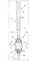
図1に示されるように、本実施形態に係る血管内薬剤溶出カテーテル10は、先端側に弾性変形部11が設けられたシャフト12と、シャフト12が挿通されるカテーテル本体13と、を有する。 As shown in FIG. 1, the intravascular
カテーテル本体13は、ルーメン20(第1ルーメン)を有するチューブ21を主な構造とする。チューブ21は、ポリアミドやポリエーテルアミドなどの弾性変形可能な軟質プラスチックの成形体である。チューブ21は、長手方向101に渡ってほぼ均等な外径である。また、ルーメン20も、長手方向101に渡ってほぼ均等な内径である。ルーメン20の内径は、弾性変形部11及びシャフト12が挿入可能な径に設定されている。チューブ21の長手方向101の長さは、ヒトの四肢などのカテーテル挿入部から患部までの長さを考慮して適宜設定されている。 The
チューブ21の基端にはハンドル部22が設けられている。ハンドル部22は、ルーメン20と連続する内部空間を有する筒状の部材である。ハンドル部22は、ポリプロピレンやABSなどの樹脂の成形体である。ハンドル部22は、チューブ21の挿抜などの操作において持ち手となり得る。図1には現されていないが、ハンドル部22には、軸方向101周りへの回転操作を容易にするために羽根が適宜設けられていてもよい。なお、本実施形態において基端側とは、血管内薬剤溶出カテーテル10が体内に挿入される向きに対して後ろ側をいう。先端側とは、血管内薬剤溶出カテーテル10が体内に挿入される向きに対して前側をいう。 A
シャフト12は、医療用ステンレス製の細長な管である。シャフト12は、フッ素樹脂などでコーティングされていてもよい。シャフト12の内部空間は、ガイドワイヤ14が挿入可能である。シャフト12は、動脈血管などの湾曲形状に沿って弾性変形可能であって、長手方向101に対して挫屈しない程度の剛性を有する。 The
シャフト12の基端にはハンドル部25が連結されている。ハンドル部25は、シャフト12の内部空間と連続する内部空間を有する筒状の部材である。ハンドル部25は、ポリプロピレンやABSなどの樹脂の成形体である。ハンドル部25は、シャフト12をカテーテル本体13に対して挿抜したり回転させたりする際や、シャフト12に対してガイドワイヤ14を挿抜する際の持ち手となり得る。 A
弾性変形部11は、シャフト12の先端に設けられている。弾性変形部11は、固定リング31、スライドリング32及び複数本の線材33を有する。固定リング31は、ガイドワイヤ14が挿通され得る円筒形状の部材である。固定リング31は、シャフト12の先端に固定されており、その内部空間がシャフト12の内部空間と連続している。 The
スライドリング32は、固定リング31に対して長尺方向101の先端側へ離間されて配置されている。スライドリング32は、ガイドワイヤ14が挿通され得る円筒形状の部材である。スライドリング32の内部空間は、固定リング31の内部空間と同じ軸線上となるように配置されている。したがって、固定リング31の内部空間に挿通されて長尺方向101の先端側へ長尺方向101に沿って延出されたガイドワイヤ14が、スライドリング32の内部空間に挿通され得る。 The
各線材33は、固定リング31とスライドリング32との間に張り渡されている。各線材33によって、固定リング31とスライドリング32とが連結されている。各線材33は、長尺方向101に沿って延出されたガイドワイヤ14を中心とする周方向102に相互に離間されて配置されている。各線材33の離間距離は、隣り合う線材33の間の空間を血液が円滑に流通可能な寸法に設定されており、具体的には、数ミリメートル程度である。 Each
各線材33は、固定リング31とスライドリング32との間において、長尺方向101に対して螺旋をなして延出されており、固定リング31及びスライドリング32において結束されている。これにより、各線材33により画定される弾性変形部11は、中央部分34の外径が最大となる籠形状の外径を呈している。ガイドワイヤ14は、この籠形状の内部空間、つまり各線材33の径方向103の内側を挿通されている。 Each
各線材33の素材としては、形状記憶合金が好ましく、具体的には、Ni−Ti系合金、Cu−Zn−Al系合金、Cu−Al−Ni系合金等が挙げられる。各線材33により記憶された形状により、弾性変形部11は、図2に示されるように、各線材33が離間されて中央部分34の外径が拡がった籠形状の拡張姿勢に維持される。そして、各線材33に対して径方向内側へ、つまりガイドワイヤ14が挿通されている中心側への外力が作用すると、図4に示されるように、各線材33が近接して中央部分34の外径が縮んだ収縮姿勢に弾性的に変形する。 The material of each
図2,3に示されるように、薬剤保持膜15は、弾性変形部11の中央部分34にのみにおいて各線材33に対して周方向102へ張り渡されている。換言すれば、薬剤保持膜15は、弾性変形部11の先端部分35及び基端部分36においては、各線材33の間には張り渡されていない。 As shown in FIGS. 2 and 3, the
薬剤保持膜15の素材としては、生体適合性を有し、所望の薬剤を保持することができ、かつ血管内において保持した薬剤を溶出することが可能な材料が好ましく、具体的には、ポリウレタン、ポリエチレン、ポリエステル、ポリプロピレン、ポリアミド、ポリテトラフルオロエチレン、ポリフッ化ビニリデン等が挙げられる。薬剤保持膜15は、弾性変形部11が拡張姿勢であるときに、中央部分34において各線材33の間に適度な張力を有して張られた状態となる。また、薬剤保持膜15は可撓性を有し、弾性変形部11が収縮姿勢であるときには、各線材33の間において撓んで、弾性変形部11の姿勢変化に追従する。 The material of the
薬剤保持膜15は、弾性変形部11が薬剤保持膜15の素材となる溶液中に浸漬されて乾燥されることによって、各線材33の間に張り渡される。このとき、弾性変形部11の先端部分35及び中央部分34のみが溶液中に浸漬されることによって、基端部分36以外の部分、つまり先端部分35及び中央部分34において、各線材33に接着された状態で各線材33の間に薬剤保持膜15が張り渡される。その後、弾性変形部11の先端部分35において、各線材33の間に張り渡された薬剤保持膜15がレーザにより切り欠かれている。その結果、図3に示されるように、先端部分35及び基端部分36においては、各線材33の間には薬剤保持膜15が存在せず、中央部分34においてのみ各線材33の間に薬剤保持膜15が張り渡された状態となる。 The
薬剤保持膜15には薬剤がコーティングされている。この薬剤は特に限定されるものではないが、冠動脈の狭窄部を拡張させた後に再狭窄を防止するための薬剤としては、パクリタキセル及びその類似体、ラパマイシン及びその類似体、β−ラパコン及びその類似体、生物学的ビタミンD及びその類似体などが挙げられる。 The
薬剤保持膜15にコーティングされた層には、前述されたような薬剤の他、血管での薬剤の放出を増強させるなどの目的のための添加剤などが含まれていてもよい。また、薬剤の層に、さらに、血管を通過しているときに薬剤の損失を防ぐための保護層が積層されてもよい。なお、薬剤は、薬剤保持膜15へのコーティングのみでなく、薬剤保持膜15への含浸によって薬剤保持膜15に保持されていてもよい。 The layer coated on the
[血管内薬剤溶出カテーテル10の使用方法]
以下に、血管内薬剤溶出カテーテル10の使用方法が説明される。[Usage method of intravascular drug elution catheter 10]
Below, the usage method of the intravascular
血管内薬剤溶出カテーテル10は、治療すべき血管壁91を有する血管90に挿入される。血管壁91は、例えば、冠動脈形成術(PTCA)において拡張された狭窄部92であって、再狭窄を防止するために薬剤を浸透させる狭窄部92である。 The intravascular
血管内薬剤溶出カテーテル10が血管90に挿入されるに先立って、血管90にガイドワイヤ14が挿通されて血管壁91へ到達されている。このようなガイドワイヤ14の挿通は、例えば、特開2006−326226号公報や特開2006−230442号公報に開示された公知の手法によりなされるので、ここでは詳細な説明が省略される。 Prior to the insertion of the intravascular
血管内薬剤溶出カテーテル10が血管90へ挿入されるときには、図5に示されるように、弾性変形部11は収縮姿勢とされてカテーテル本体13のルーメン20に収容されている。薬剤保持膜15も弾性変形部11の収縮に追従して収縮されてルーメン20に収容されている。この状態の血管内薬剤溶出カテーテル10の先端側、つまり、カテーテル本体13の先端側から、弾性変形部11のスライドリング32にガイドワイヤ14の基端が挿入される。ガイドワイヤ14は、更に弾性変形部11の内部空間から固定リング31に挿通され、シャフト12の内部空間へ挿通される。そして、血管内薬剤溶出カテーテル10が、ガイドワイヤ14に沿って血管90に挿入される。 When the intravascular
図5に示されるように、カテーテル本体13の先端側が血管壁91の狭窄部92の近傍へ到達すると、ハンドル部22,25が操作されて、カテーテル本体13に対してシャフト12が挿入される。つまり、シャフト12がカテーテル本体13に対して相対的に先端側へ押し出される。これにより、カテーテル本体13のルーメン20から弾性変形部11が押し出される。図6に示されるように、押し出された弾性変形部11は、収縮姿勢から拡張姿勢へ弾性的に復帰して拡張姿勢を維持する。弾性変形部11の姿勢変化に伴って、つまり弾性変形部11が籠形状となることに伴って、薬剤保持膜15が各線材33に対して周方向へ張り渡された状態となる。この薬剤保持膜15が血管壁91の狭窄部92に圧接する。薬剤保持膜15の狭窄部92への圧接が所定の時間だけ保持されることによって、薬剤保持膜15から狭窄部92へ薬剤が浸透される。 As shown in FIG. 5, when the distal end side of the catheter
薬剤保持膜15は、弾性変形部11の中央部分34においてのみ各線材33に対して周方向へ張り渡されており、先端部分35及び基端部分36においては、各線材33の間に薬剤保持膜15が存在しない。したがって、拡張姿勢の弾性変形部11が血管90に放置されている間において、血管90を流れる血液は、弾性変形部11を先端部分35から基端部分36へ、或いは基端部分36から先端部分35へ流通可能である。勿論、籠形状の弾性変形部11の内部空間に対しても血液は流通可能である。したがって、拡張姿勢の弾性変形部11によって薬剤保持膜15が狭窄部92に圧接されている間において、血管90が閉塞されて血流が遮断されることがない。 The
狭窄部92へ薬剤を浸透させるための所定の時間が経過すると、ハンドル部22,25が操作されて、カテーテル本体13に対してシャフト12が引き出される。つまり、シャフト12がカテーテル本体13に対して相対的に基端側へ引き戻される。これにより、拡張姿勢の弾性変形部11がカテーテル本体13のルーメン20に引き込まれる。弾性変形部11において固定リング31から基端部分36、中央部分34へは、各線材33が径方向103外側へ連続的に拡がるように延出されているので、カテーテル本体13の先端をガイドとして、各線材33が径方向103の内側へ弾性変形される。これにより、弾性変形部11は、次第に拡張姿勢から収縮姿勢へ姿勢変化されながら、カテーテル本体13のルーメン20に収容される。薬剤保持膜15は、弾性変形部11の姿勢変化に追従して、中央部分34において各線材33の間に張り渡された状態から、各線材33の間において撓んだ状態となる。そして、弾性変形部11が完全にカテーテル本体13のルーメン20に収容されると、血管内薬剤溶出カテーテル10が血管90から引き抜かれる。 When a predetermined time for allowing the drug to penetrate into the narrowed
[本実施形態の作用効果]
本実施形態に係る血管内薬剤溶出カテーテル10によれば、血管内薬剤溶出カテーテル10が血管90へ挿入されるときには、弾性変形部11は収縮姿勢とされてカテーテル本体13のルーメン20に収容され、カテーテル本体13の先端側が血管壁91の狭窄部92の近傍へ到達すると、カテーテル本体13に対してシャフト12が挿入されて、カテーテル本体13のルーメン20から弾性変形部11が押し出されて収縮姿勢から拡張姿勢へ弾性的に復帰して薬剤保持膜15が狭窄部92と圧接するので、薬剤保持膜15に保持された薬剤を狭窄部92へ浸透させることができる。[Operational effects of this embodiment]
According to the intravascular
また、薬剤保持膜15は、弾性変形部11の中央部分34においてのみ各線材33に対して周方向102へ張り渡されているので、弾性変形部11が拡張姿勢を維持した状態において、先端部分35から基端部分36に渡って血液が流通可能である。これにより、末梢側への血流を遮断することなく血管90において弾性変形部11を拡張させた姿勢を所望の時間だけ保持することができる。 Further, since the
また、薬剤保持膜15が弾性変形部11の中央部分34から先端部分35に渡って各線材33の間に張り渡されてから、先端部分35において各線材33間の薬剤保持膜15が切り欠かれているので、カテーテル本体13のルーメン20に収容された弾性変形部11が外側へ押し出されるときに、ルーメン20において、カテーテル本体13の内壁に対して薬剤保持膜15が摺動しても、弾性変形部11の各線材33に対して薬剤保持膜15の位置ズレが生じにくい。また、弾性変形部11の先端部分35において、各線材33の間が切り欠かれているので、先端部分35において血液の流通が薬剤保持膜15により妨げらることがない。 Further, after the
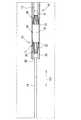
[変形例]
以下に、前述された実施形態の変形例が説明される。前述された実施形態では、カテーテル本体13がオーバー・ザ・ワイヤー・タイプであるのに対して、この変形例では、モノレール・タイプであり、ガイドワイヤ14が、シャフト41内を挿通されておらず、いわゆるダブルルーメン・タイプのカテーテル本体42にガイドワイヤ14が挿通されている点において、前述された実施形態と異なる。なお、弾性変形部11は前述された実施形態と同じ構造であり、前述された実施形態において同じ参照符号で示されている。[Modification]
Below, the modification of embodiment mentioned above is demonstrated. In the above-described embodiment, the
図7に示されるように、カテーテル本体42は、2つのルーメン43,44を有する。ルーメン43(第1ルーメン)は、チューブ45の内部空間により形成されている。ルーメン44(第2ルーメン)は、チューブ46の内部空間により形成されている。2つのチューブ45,46は、それぞれルーメン43,44が並列するように並んだ状態で連結されている。ルーメン43には、シャフト41が挿通される。ルーメン44には、ガイドワイヤ14が挿通される。 As shown in FIG. 7, the
チューブ45,46の長尺方向101の長さは、血管90において挿入位置から患部までの距離に対して十分に短い。したがって、チューブ46において、ガイドワイヤ14の一部のみがルーメン44に挿通される。 The lengths of the
チューブ45の基端には、カテーテルシャフト47が連結されて長尺方向101へ延出されている。カテーテルシャフト47は、医療用ステンレス製の線材であり、血管90の湾曲形状に沿って弾性的に曲がる弾性を有し、かつ長手方向101に対して座屈しない程度の剛性を有する。図7には現れていないが、カテーテルシャフト47の基端側には、ハンドル部22と同様のハンドル部が設けられている。 A
シャフト41は、医療用ステンレス製の線材である。シャフト41は、血管90の湾曲形状に沿って弾性変形可能であって、長手方向101に対して挫屈しない程度の剛性を有する。シャフト41の先端側に弾性変形部11が設けられている。シャフト41の先端側は、弾性変形部11の固定リング31及びスライドリング32に挿通されている。固定リング31は、シャフト41に固定されている。スライドリング32は、シャフト41に対してスライド可能である。 The
チューブ45のルーメン43には、収縮姿勢の弾性変形部11が収容され得る。そして、シャフト41がカテーテル本体42に対して相対的に先端側へ押し出されと、カテーテル本体42のルーメン43から弾性変形部11が押し出されて、図7に示されるように、押し出された弾性変形部11が、収縮姿勢から拡張姿勢へ弾性的に復帰して拡張姿勢を維持する。また、シャフト41がカテーテル本体42に対して相対的に基端側へ引き戻されると、拡張姿勢の弾性変形部11が収縮姿勢に姿勢変化しながらカテーテル本体42のルーメン43に引き込まれる。このような変形例によっても、前述された実施形態と同様の作用効果が奏される。 The
10・・・血管内薬剤溶出カテーテル
11・・・弾性変形部
12,41・・・シャフト
13,42・・・カテーテル本体
14・・・ガイドワイヤ
15・・・薬剤保持膜
20,43・・・ルーメン(第1ルーメン)
33・・・線材
34・・・中央部分
35・・・先端部分
44・・・ルーメン(第2ルーメン)DESCRIPTION OF
33 ...
Claims (4)
Translated fromJapanese上記弾性変形部が先端側に設けられたシャフトと、
上記収縮姿勢の上記弾性変形部及び上記シャフトが挿通可能な第1ルーメンを有するカテーテル本体と、
上記弾性変形部の中央部分においてのみ上記拡張姿勢における各線材に対して周方向へ張り渡されており、上記弾性変形部の姿勢変化に追従する可撓性を有し、薬剤の保持及び溶出が可能な薬剤保持膜と、
上記薬剤保持膜に保持された薬剤と、を具備し、
上記弾性変形部は、上記各線材が上記長尺方向に対して螺旋をなして延出されており、当該各線材の両端が結束されて上記中央部分が最大径とされており、当該中央部分において当該各線材が交差していない血管内薬剤溶出カテーテル。A plurality of wires are spaced apart in the circumferential direction, and each wire rod is spaced apart to maintain an elongate outer shape in which the outer diameter of the central portion in the longitudinal direction is widened. An elastically deformable portion that elastically deforms into a contracted posture in which the outer diameter of the portion is reduced;
A shaft provided with the elastic deformation portion on the tip side;
A catheter body having a first lumen through which the elastically deformable portion in the contracted posture and the shaft can be inserted;
It is stretched in the circumferential direction only with respect to each wire in the expanded posture only at the central portion of the elastic deformation portion, has flexibility to follow the posture change of the elastic deformation portion, and retains and elutes the drug. A possible drug retaining membrane,
A drug held on the drug holding film,
The elastically deforming portion is formed by extending each wire rod in a spiral with respect to the longitudinal direction, binding both ends of each wire rod so that the central portion has a maximum diameter, and the central portion An intravascular drug-eluting catheter in which the wires do not intersect.
上記弾性変形部は、各線材に対して径方向の内側をガイドワイヤが挿通可能なものである請求項1又は2に記載の血管内薬剤溶出カテーテル。The shaft is a tube body through which a guide wire can be inserted,
The intravascular drug-eluting catheter according to claim 1 or 2, wherein the elastically deformable portion is capable of inserting a guide wire through a radial inner side with respect to each wire.
上記弾性変形部は、各線材に対して径方向の内側をシャフトが挿通可能なものである請求項1から3のいずれか一項に記載の血管内薬剤溶出カテーテル。The catheter body has a second lumen through which a guide wire can be inserted,
The intravascular drug-eluting catheter according to anyone of claims 1 to 3, wherein the elastically deformable portion is capable of inserting a shaft through a radially inner side with respect to each wire.
Priority Applications (4)
| Application Number | Priority Date | Filing Date | Title |
|---|---|---|---|
| JP2010165553AJP5799488B2 (en) | 2010-07-23 | 2010-07-23 | Intravascular drug elution catheter |
| US13/805,824US20130116634A1 (en) | 2010-07-23 | 2011-07-21 | Intravascular drug elution-type catheter |
| EP11809685.8AEP2596829A4 (en) | 2010-07-23 | 2011-07-21 | Intravascular drug elution-type catheter |
| PCT/JP2011/066511WO2012011515A1 (en) | 2010-07-23 | 2011-07-21 | Intravascular drug elution-type catheter |
Applications Claiming Priority (1)
| Application Number | Priority Date | Filing Date | Title |
|---|---|---|---|
| JP2010165553AJP5799488B2 (en) | 2010-07-23 | 2010-07-23 | Intravascular drug elution catheter |
Publications (2)
| Publication Number | Publication Date |
|---|---|
| JP2012024316A JP2012024316A (en) | 2012-02-09 |
| JP5799488B2true JP5799488B2 (en) | 2015-10-28 |
Family
ID=45496933
Family Applications (1)
| Application Number | Title | Priority Date | Filing Date |
|---|---|---|---|
| JP2010165553AActiveJP5799488B2 (en) | 2010-07-23 | 2010-07-23 | Intravascular drug elution catheter |
Country Status (4)
| Country | Link |
|---|---|
| US (1) | US20130116634A1 (en) |
| EP (1) | EP2596829A4 (en) |
| JP (1) | JP5799488B2 (en) |
| WO (1) | WO2012011515A1 (en) |
Families Citing this family (1)
| Publication number | Priority date | Publication date | Assignee | Title |
|---|---|---|---|---|
| US20150094559A1 (en)* | 2013-09-27 | 2015-04-02 | Covidien Lp | Modular physiological sensing patch |
Family Cites Families (11)
| Publication number | Priority date | Publication date | Assignee | Title |
|---|---|---|---|---|
| FR2624747A1 (en)* | 1987-12-18 | 1989-06-23 | Delsanti Gerard | REMOVABLE ENDO-ARTERIAL DEVICES FOR REPAIRING ARTERIAL WALL DECOLLEMENTS |
| US5071407A (en)* | 1990-04-12 | 1991-12-10 | Schneider (U.S.A.) Inc. | Radially expandable fixation member |
| US6641611B2 (en) | 2001-11-26 | 2003-11-04 | Swaminathan Jayaraman | Therapeutic coating for an intravascular implant |
| JP4656494B2 (en) | 2005-02-22 | 2011-03-23 | ニプロ株式会社 | Guiding catheter |
| JP2006326226A (en) | 2005-05-30 | 2006-12-07 | Nipro Corp | Guiding catheter |
| US20080058856A1 (en)* | 2005-06-28 | 2008-03-06 | Venkatesh Ramaiah | Non-occluding dilation device |
| EP2322235A1 (en) | 2006-11-20 | 2011-05-18 | Lutonix, Inc. | Drug releasing coatings for medical devices |
| JP5172180B2 (en)* | 2007-03-19 | 2013-03-27 | トーヨーエイテック株式会社 | DLC film modification method, medical material, and medical device manufacturing method |
| US8100855B2 (en)* | 2007-09-17 | 2012-01-24 | Abbott Cardiovascular Systems, Inc. | Methods and devices for eluting agents to a vessel |
| US8066757B2 (en)* | 2007-10-17 | 2011-11-29 | Mindframe, Inc. | Blood flow restoration and thrombus management methods |
| JP2011505201A (en)* | 2007-11-30 | 2011-02-24 | クック・インコーポレイテッド | Method and apparatus for vascular therapy |
- 2010
- 2010-07-23JPJP2010165553Apatent/JP5799488B2/enactiveActive
- 2011
- 2011-07-21EPEP11809685.8Apatent/EP2596829A4/ennot_activeWithdrawn
- 2011-07-21WOPCT/JP2011/066511patent/WO2012011515A1/enactiveApplication Filing
- 2011-07-21USUS13/805,824patent/US20130116634A1/ennot_activeAbandoned
Also Published As
| Publication number | Publication date |
|---|---|
| US20130116634A1 (en) | 2013-05-09 |
| EP2596829A1 (en) | 2013-05-29 |
| EP2596829A4 (en) | 2017-11-01 |
| JP2012024316A (en) | 2012-02-09 |
| WO2012011515A1 (en) | 2012-01-26 |
Similar Documents
| Publication | Publication Date | Title |
|---|---|---|
| JP5728779B2 (en) | Intravascular hemostasis catheter | |
| AU2013290294B2 (en) | Expandable guide extension catheter | |
| US20170028170A1 (en) | Guide catheter extension device and methods of use for cardiology procedures | |
| US10124148B2 (en) | Guide extension catheter with trackable tip and related methods of use | |
| JP6179995B2 (en) | Reinforced stretch medical device and manufacturing method | |
| US9956384B2 (en) | Articulating balloon catheter and method for using the same | |
| JP4562197B2 (en) | Balloon catheter assembly | |
| US20140025043A1 (en) | Guide extension catheter | |
| US20080269641A1 (en) | Method of using a guidewire with stiffened distal section | |
| JP2015524737A (en) | Guide extension catheter | |
| WO2013008087A1 (en) | Guide wire incorporating a handle | |
| JP2014533191A (en) | Vascular protective film | |
| WO2009140214A1 (en) | Sleeves for positioning a stent on a delivery balloon cathether system | |
| WO2014093879A1 (en) | Medical devices with a locking member | |
| JP5887348B2 (en) | Therapy device | |
| JP7230137B2 (en) | catheter assembly | |
| JP2016007368A (en) | Fluid flow non-blocking balloon catheter | |
| JP2013223663A (en) | Protective sleeve for balloon catheter, balloon catheter system, and stent delivery system | |
| JP5799488B2 (en) | Intravascular drug elution catheter | |
| US20050107819A1 (en) | Catheter with a sectional guidewire shaft | |
| JP2018187229A (en) | Medical long body | |
| JP5875185B2 (en) | Stent delivery catheter | |
| WO2023189377A1 (en) | Catheter | |
| JP2014069034A (en) | Balloon catheter | |
| WO2023189378A1 (en) | Catheter |
Legal Events
| Date | Code | Title | Description |
|---|---|---|---|
| A621 | Written request for application examination | Free format text:JAPANESE INTERMEDIATE CODE: A621 Effective date:20130607 | |
| A131 | Notification of reasons for refusal | Free format text:JAPANESE INTERMEDIATE CODE: A131 Effective date:20140520 | |
| A521 | Request for written amendment filed | Free format text:JAPANESE INTERMEDIATE CODE: A523 Effective date:20140703 | |
| A131 | Notification of reasons for refusal | Free format text:JAPANESE INTERMEDIATE CODE: A131 Effective date:20150120 | |
| A521 | Request for written amendment filed | Free format text:JAPANESE INTERMEDIATE CODE: A523 Effective date:20150209 | |
| TRDD | Decision of grant or rejection written | ||
| A01 | Written decision to grant a patent or to grant a registration (utility model) | Free format text:JAPANESE INTERMEDIATE CODE: A01 Effective date:20150728 | |
| A61 | First payment of annual fees (during grant procedure) | Free format text:JAPANESE INTERMEDIATE CODE: A61 Effective date:20150810 | |
| R150 | Certificate of patent or registration of utility model | Ref document number:5799488 Country of ref document:JP Free format text:JAPANESE INTERMEDIATE CODE: R150 | |
| R250 | Receipt of annual fees | Free format text:JAPANESE INTERMEDIATE CODE: R250 | |
| R250 | Receipt of annual fees | Free format text:JAPANESE INTERMEDIATE CODE: R250 |