JP5797456B2 - Input device - Google Patents
Input deviceDownload PDFInfo
- Publication number
- JP5797456B2 JP5797456B2JP2011114542AJP2011114542AJP5797456B2JP 5797456 B2JP5797456 B2JP 5797456B2JP 2011114542 AJP2011114542 AJP 2011114542AJP 2011114542 AJP2011114542 AJP 2011114542AJP 5797456 B2JP5797456 B2JP 5797456B2
- Authority
- JP
- Japan
- Prior art keywords
- vibrator
- touch panel
- input device
- detection
- time
- Prior art date
- Legal status (The legal status is an assumption and is not a legal conclusion. Google has not performed a legal analysis and makes no representation as to the accuracy of the status listed.)
- Expired - Fee Related
Links
- 238000001514detection methodMethods0.000claimsdescription61
- 230000035807sensationEffects0.000description7
- 238000012986modificationMethods0.000description6
- 230000004048modificationEffects0.000description6
- 238000006073displacement reactionMethods0.000description4
- 230000000694effectsEffects0.000description4
- 238000000034methodMethods0.000description4
- 239000011521glassSubstances0.000description3
- 238000004364calculation methodMethods0.000description2
- 238000010586diagramMethods0.000description2
- 230000006870functionEffects0.000description2
- 238000004519manufacturing processMethods0.000description2
- 238000012545processingMethods0.000description2
- 238000004458analytical methodMethods0.000description1
- 238000013459approachMethods0.000description1
- 238000007796conventional methodMethods0.000description1
- 238000012937correctionMethods0.000description1
- 229920001971elastomerPolymers0.000description1
- 229920002635polyurethanePolymers0.000description1
- 239000004814polyurethaneSubstances0.000description1
- 239000005060rubberSubstances0.000description1
- 239000004065semiconductorSubstances0.000description1
- 229920002379silicone rubberPolymers0.000description1
- 239000004945silicone rubberSubstances0.000description1
- 229920003051synthetic elastomerPolymers0.000description1
- 229920003002synthetic resinPolymers0.000description1
- 239000000057synthetic resinSubstances0.000description1
- 239000005061synthetic rubberSubstances0.000description1
Images


Landscapes
- Position Input By Displaying (AREA)
- User Interface Of Digital Computer (AREA)
Description
Translated fromJapanese本発明は、入力装置に関する。 The present invention relates to an input device.
従来の技術として、触れた点に基づいた信号を出力するタッチパッド部と、タッチパッド部からの信号に基づいて信号の解析を行って座標点を算出し、算出した座標点の情報を含む信号を出力する信号解析部と、を備えたキーボードタッチパッドが知られている(例えば、特許文献1参照。)。 As a conventional technique, a touch pad unit that outputs a signal based on a touched point, and a signal that includes information on the calculated coordinate point by analyzing the signal based on the signal from the touch pad unit and calculating a coordinate point There is known a keyboard touchpad provided with a signal analysis unit that outputs (see, for example, Patent Document 1).
このキーボードタッチパッドのタッチパッド部の下には、キーの位置を表示するシートが設けられ、タッチパッド部を介してキー配列が認識でき、さらに、タッチパッド部には、ホームポジション(タッチパッド部の基準位置)を示す小さな突起物を備えている。操作者は、この突起物を触ることによりホームポジションを認識することができる。 Below the touch pad portion of the keyboard touch pad, a sheet for displaying the key position is provided, the key arrangement can be recognized via the touch pad portion, and the home position (touch pad portion) A small projection indicating the reference position). The operator can recognize the home position by touching the protrusion.
しかし、従来のキーボードタッチパッドは、ホームポジションを示す小さな突起物がタッチパッド部に設けられているので、その位置を変更することができない。 However, since the conventional keyboard touchpad is provided with a small protrusion on the touchpad portion that indicates the home position, the position cannot be changed.
従って、本発明の目的は、検出面において、他の領域と異なる触感を与える領域を任意の位置に形成することができる入力装置を提供することにある。 Therefore, an object of the present invention is to provide an input device that can form a region that gives a tactile sensation different from other regions at an arbitrary position on the detection surface.
本発明の一態様は、検出面に対する接触に基づく検出信号を出力する検出部と、検出面の任意の位置に回転中心が存在するように、検出面に対して平行な方向である第1の方向と第1の方向の逆方向である第2の方向に検出部を振動させ、検出部を時計回り及び反時計回りに回転させる振動発生部と、を備える入力装置を提供する。One aspect of the present invention is a detection unit that outputs a detection signal based on contact with a detection surface,and a first directionthat is parallel to the detection surface so that a rotation center exists at anarbitrary position on the detection surface. vibrate the detecting unitin the second direction is a direction opposite to the direction of the firstdirection, to provide an input device and a vibration generating unit you wantto rotate. clockwise and counterclockwise detection unit.
本発明によれば、検出面において、他の領域と異なる触感を与える領域を任意の位置に形成することができる。 According to the present invention, it is possible to form a region that gives a tactile sensation different from other regions at any position on the detection surface.
[実施の形態]
(実施の形態の要約)
実施の形態に係る入力装置は、検出面に対する接触に基づく検出信号を出力する検出部と、検出面に回転中心が存在するように、第1の方向と第1の方向の逆方向である第2の方向に検出部を振動させる振動発生部と、を備える。[Embodiment]
(Summary of embodiment)
The input device according to the embodiment includes a detection unit that outputs a detection signal based on contact with the detection surface, and a first direction that is opposite to the first direction so that the rotation center exists on the detection surface. A vibration generation unit that vibrates the detection unit in the direction of 2.
(入力装置1の構成)
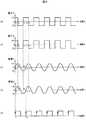
図1(a)は、実施の形態に係る入力装置の斜視図であり、(b)は、入力装置の上面図であり、(c)は、入力装置のブロック図である。図2(a)は、実施の形態に係る第1の振動子に供給される駆動信号の時間変化を示すグラフであり、(b)は、第2の振動子に供給される駆動信号の時間変化を示すグラフであり、(c)は、第1の振動子の振幅の時間変化を示すグラフであり、(d)は、第2の振動子の振幅の時間変化を示すグラフであり、(e)は、タッチパネルの検出信号を取得するタイミングを示すグラフである。図1(a)では、センサワイヤ12の一部を点線で示している。図1(b)では、最大振幅で回転したタッチパネル10を点線で示している。図2(a)及び(b)は、縦軸が電圧V、横軸が時間tである。図2(c)及び(d)は、縦軸が振幅d、横軸が時間tである。図2(e)は、横軸が時間tである。なお、実施の形態に係る各図において、部品と部品との比率は、実際の比率とは異なる場合がある。(Configuration of input device 1)
FIG. 1A is a perspective view of an input device according to an embodiment, FIG. 1B is a top view of the input device, and FIG. 1C is a block diagram of the input device. FIG. 2A is a graph showing a time change of the drive signal supplied to the first vibrator according to the embodiment, and FIG. 2B is a time of the drive signal supplied to the second vibrator. (C) is a graph showing the time change of the amplitude of the first vibrator, (d) is a graph showing the time change of the amplitude of the second vibrator, e) is a graph showing the timing for acquiring the detection signal of the touch panel. In FIG. 1A, a part of the
図1(a)におけるXYZ座標系は、直交座標系であり、X軸がタッチパネル10の長手方向に平行な軸であり、Y軸がタッチパネル10の短手方向に平行な軸であり、Z軸がタッチパネル10の検出面100の法線方向に平行な軸である。XYZ座標系の原点は、例えば、タッチパネル10の左上(図1(b)の紙面左上)である。なお、検出面100は、平坦であるものとする。 The XYZ coordinate system in FIG. 1A is an orthogonal coordinate system, the X axis is an axis parallel to the longitudinal direction of the
実施の形態に係る入力装置1は、主に、検出面100に対する接触に基づく検出信号を出力する検出部としてのタッチパネル10と、検出面100に回転中心11が存在するように、第1の方向301と第1の方向301の逆方向である第2の方向302にタッチパネル10を振動させる振動発生部20と、を備える。 The input device 1 according to the embodiment mainly includes a
この入力装置1は、第1の振動子21及び第2の振動子22によって、図1(b)の紙面の時計回り及び反時計回りにタッチパネル10を回転させることで、他の領域と触感が異なる回転中心11を形成する。操作者は、検出面100に触ることにより、他の領域と異なる触感となる回転中心11を認識することが可能となる。 The input device 1 has a tactile sensation with other regions by rotating the
また、入力装置1は、例えば、接続された電子機器の操作を行うことができるものである。入力装置1は、例えば、操作者の体の一部(例えば、指)や専用のペンで検出面100に触れることにより、電子機器に表示されたカーソルの移動やカーソルによる選択、表示されたアイコンのドラッグ、ドロップ等の指示を行うことができるように構成されている。本実施の形態では、指による操作について説明する。 In addition, the input device 1 is capable of operating a connected electronic device, for example. For example, the input device 1 touches the
ここで、操作者は、例えば、入力装置1に対してタッチ操作、タップ操作、スライド(なぞり)操作およびジェスチャ操作等を行うことができる。ここで、タッチ操作とは、例えば、指で検出面100に接触する操作を示す。タップ操作は、タッチ操作よりも短い時間で入力装置1に接触する操作であり、所定の時間内に複数回繰り返すことで、回数に応じた異なる機能を実行させる操作を示す。また、スライド操作とは、例えば、指を検出面100に接触させたまま移動させる操作を示す。ジェスチャ操作とは、例えば、操作指の軌跡が予め定められた形状と相似であるとき、その形状に割り当てられた機能を実行させる操作を示す。ジェスチャ操作の判定は、例えば、パターンマッチングを用いた方法等の周知の方法が用いられる。 Here, for example, the operator can perform a touch operation, a tap operation, a slide (tracing) operation, a gesture operation, and the like on the input device 1. Here, the touch operation indicates an operation of touching the
・タッチパネル10の構成
タッチパネル10は、例えば、周知の抵抗膜方式、静電容量方式等のタッチパネルである。-Configuration of the
本実施の形態に係るタッチパネル10は、例えば、検出面100に指が近づくことによる、センサワイヤ12と指との距離に反比例した電流の変化を検出する静電容量方式のタッチパネルである。このタッチパネル10は、例えば、上部にガラス平板を備え、そのガラス平板の下に、複数のセンサワイヤ12が設けられている。検出面100は、例えば、このガラス平板の表面である。 The
図1(a)に示すX軸方向には、例えば、m個のセンサワイヤ12が等間隔で並べられている。このmは、例えば、正の整数である。また、図1(a)に示すY軸方向には、例えば、n個のセンサワイヤ12が等間隔で並べられている。このnは、例えば、正の整数である。 In the X-axis direction shown in FIG. 1A, for example,
X軸に沿って並べられたセンサワイヤ12は、例えば、Y軸に沿って並べられたセンサワイヤ12よりも検出面100に近い層に形成されている。また、X軸に沿って並べられたセンサワイヤ12は、例えば、Y軸に沿って並べられたセンサワイヤ12と電気的に絶縁されている。 The
このタッチパネル10は、例えば、図1(c)に示すように、後述する制御部13に接続され、接触が検出された検出面100の位置を示す検出信号を制御部13に出力するように構成されている。 For example, as shown in FIG. 1C, the
また、タッチパネル10は、例えば、入力装置1の筐体(図示せず)に振動が可能となるように、支持されているものとする。具体的には、例えば、第1の振動子21、第2の振動子22、第1の弾性部材31及び第2の弾性部材32が筐体に支持されている。他の支持としては、例えば、ゴム等の弾性部材をタッチパネル10と筐体との間に介在させ支持する構成であっても良い。また、以下では、第1の振動子21及び第2の振動子22による振動が停止している場合のタッチパネル10の位置を初期位置と呼ぶものとする。タッチパネル10は、振動が停止した後に、初期位置に復帰するように、支持されているものとする。 Moreover, the
ここで、以下では、図1(b)の紙面においてタッチパネル10の長手方向上部の側面を第1の側面101、長手方向下部の側面を第2の側面102、短手方向右の側面を第3の側面103、及び短手方向左の側面を第4の側面104とする。 Here, in the following, on the paper surface of FIG. 1B, the upper side surface in the longitudinal direction of the
・振動発生部20の構成
振動発生部20は、例えば、タッチパネル10の一方の側面に配置され、タッチパネル10に振動を与える第1の振動子21と、一方の側面の反対側の他方の側面に配置され、タッチパネル10に振動を与える第2の振動子22と、を備えて概略構成されている。また、振動発生部20は、例えば、さらに、駆動部23を備えている。第1の振動子21及び第2の振動子22は、例えば、ピエゾ効果又は磁気歪効果等により振動を行う振動子である。本実施の形態に係る第1の振動子21及び第2の振動子22は、一例として、ピエゾ効果を用いた振動子であるものとする。-Configuration of Vibration Generation Unit 20 The vibration generation unit 20 is disposed on one side surface of the
第1の振動子21及び第2の振動子22は、電圧を加えると伸び縮みするピエゾ素子(圧電素子)を含んで概略構成され、このピエゾ素子に電圧を加えることで伸び縮みを行って対象物に振動を与える振動子である。この振動の周波数は、数百Hz程度(一例として、250Hz〜500Hz)である。 The
また、この振動子の振幅は、一例として、数μmpp程度である。従って、タッチパネル10が振動を行う様子を図示することは困難であるため、図1(b)に示すように、図示し易い大きな振幅としている。また、第1の振動子21は、第1の方向301、すなわち、伸びる方向における最大振幅が+d1であり、第2の方向302、すなわち、縮む方向における最大振幅が−d1である。第2の振動子22は、第2の方向302、すなわち、伸びる方向における最大振幅が+d2であり、第1の方向301、すなわち、縮む方向における最大振幅が−d2である。Moreover, the amplitude of this vibrator is about several μmpp as an example. Therefore, since it is difficult to illustrate how the
振動発生部20は、例えば、図1(a)及び(b)に示すように、一対の振動子(第1の振動子21及び第2の振動子22)が検出面100の中央を対称点として点対称となるように配置される。なお、この一対の振動子の配置は、点対称に限定されない。つまり、一対の振動子は、少なくとも一方が、点対称となる位置からずれて配置されていても良い。 For example, as shown in FIGS. 1A and 1B, the vibration generator 20 includes a pair of vibrators (a
第1の振動子21と第2の振動子22は、例えば、タッチパネル10の長手方向の側面に接するように配置されている。 The
第1の振動子21は、例えば、図1(a)に示すように、第1の側面101の左端部に接するように配置され、Y軸の正方向及び負方向、つまり、第1の方向301及び第2の方向302に振動する。 For example, as illustrated in FIG. 1A, the
第2の振動子22は、例えば、図1(a)に示すように、第1の側面101の反対側の側面となる第2の側面102の右端部に接するように配置され、Y軸の正方向及び負方向、つまり、第1の方向301及び第2の方向302に振動する。 For example, as shown in FIG. 1A, the
なお、第1の振動子21及び第2の振動子22は、振動を行っている間、タッチパネル10との接触が保たれている。 Note that the
第1の振動子21及び第2の振動子22は、例えば、回転中心11を形成しない、すなわち、タッチパネル10をX軸又はY軸に平行に変位させる位置には配置されない。従って、第1の振動子21及び第2の振動子22は、長手方向の第1の側面101及び第2の側面102、又は短手方向の第3の側面103及び第4の側面104にそれぞれ配置されることが好ましく、かつ、振動子がタッチパネル10を介して向かい合わないことが好ましい。 For example, the
ここで、本実施の形態では、第1の方向301がY軸の正方向に平行な方向であり、第2の方向302がY軸の負方向に平行な方向であった。しかし、これに限定されず、第1の振動子21が短手方向の第4の側面104に配置され、第2の振動子22が第3の側面103に配置された場合は、例えば、第1の方向301がX軸の正方向に平行な方向となり、第2の方向302がX軸の負方向に平行な方向となる。 Here, in the present embodiment, the
この第1の振動子21及び第2の振動子22は、例えば、駆動部23に接続されている。この駆動部23は、制御部13から取得した制御信号に基づいて第1の振動子21及び第2の振動子22に駆動信号を出力するように構成されている。第1の振動子21に供給される駆動信号は、例えば、図2(a)に示すように、電圧が+V1と−V1を周期的に繰り返す矩形波である。第2の振動子22に供給される駆動信号は、例えば、図2(b)に示すように、+V2と−V2を周期的に繰り返す矩形波である。The
・第1の弾性部材31及び第2の弾性部材32の構成
入力装置1は、さらに、第1の弾性部材31及び第2の弾性部材32を備えている。この第1の弾性部材31及び第2の弾性部材32は、例えば、タッチパネル10が初期位置にあるとき、弾性力を蓄積している状態にあるものとする。すなわち、第1の弾性部材31は、タッチパネル10が初期位置にあるとき、第1の方向301の弾性力をタッチパネル10に付加している。また、第2の弾性部材32は、タッチパネル10が初期位置にあるとき、第2の方向302の弾性力をタッチパネル10に付加している。この弾性力により、第1の弾性部材31及び第2の弾性部材32は、振動が発生している状態においても、タッチパネル10との接触を保っている。また、この弾性力により、第1の振動子21及び第2の振動子22とタッチパネル10との接触が保たれる。Configuration of first elastic member 31 and second elastic member 32 The input device 1 further includes a first elastic member 31 and a second elastic member 32. For example, the first elastic member 31 and the second elastic member 32 are assumed to be in a state of accumulating elastic force when the
第1の弾性部材31及び第2の弾性部材32は、例えば、弾性を有する部材であり、ポリウレタン等の合成樹脂、シリコーンゴム等の合成ゴム等を用いて形成される。 The first elastic member 31 and the second elastic member 32 are elastic members, for example, and are formed using a synthetic resin such as polyurethane, a synthetic rubber such as silicone rubber, or the like.
第1の弾性部材31は、例えば、図1(a)に示すように、第1の側面101の右端部に接するように配置されている。第2の弾性部材32は、例えば、図1(a)に示すように、第2の側面102の左端部に接するように配置されている。なお、第1の弾性部材31及び第2の弾性部材32の配置は、例えば、振動が停止している際に、タッチパネル10を初期位置に復帰させる弾性力を付加することができる位置であれば良い。 For example, as shown in FIG. 1A, the first elastic member 31 is disposed so as to contact the right end portion of the
・制御部13の構成
入力装置1は、さらに、タッチパネル10が初期位置にあるとき、タッチパネル10から検出信号を取得する制御部13を有する。-Configuration of
制御部13は、例えば、プログラムに従って、取得した情報に演算、加工等を行うCPU(Central Processing Unit)、半導体メモリであるRAM(Random Access Memory)およびROM(Read Only Memory)等から構成されるマイクロコンピュータである。 The
制御部13は、例えば、取得した検出信号に基づいた座標値から、指が接触、または近づいた座標を算出する。この座標の算出方法は、例えば、加重平均を用いた方法等の周知の方法が用いられる。制御部13は、例えば、算出した座標の情報を含む操作信号を生成して出力するように構成されている。 For example, the
制御部13は、例えば、タッチパネル10が振動しているとき、回転中心11から離れるに従って、指の検出に誤差が生じる可能性があるので、タッチパネル10が初期位置にあるタイミングで、検出信号を取得するように構成されている。検出信号の取得は、例えば、図2(a)〜(e)に示すように、振動子が電圧を供給されてから伸縮を行うまでのタイムラグ等を考慮し、電圧+V1及び電圧+V2の供給が開始される時間と、電圧−V1及び電圧−V2の供給が開始される時間と、の中央の時間に補正値を加算した時間に行われる。すなわち、図2(e)に示す検出信号の取得のためのトリガ信号は、上記に示した位相の遅れを考慮して、図2(a)に示す駆動信号を所定の時間ディレイして生成される。なお、検出信号の取得のタイミングは、例えば、タッチパネル10の初期位置を検出するセンサを設け、このセンサの信号をトリガとしても良い。For example, when the
(動作)
以下に、本実施の形態に係る入力装置1の動作について各図を参照しながら詳細に説明する。まず、回転中心11がタッチパネル10の中央に形成される場合の動作について説明する。(Operation)
Hereinafter, the operation of the input apparatus 1 according to the present embodiment will be described in detail with reference to the drawings. First, an operation when the
・回転中心11を中央に形成する場合
回転中心11をタッチパネル10の中央に形成する場合、第1の振動子21及び第2の振動子22の位相、振幅を同位相及び同振幅にする必要がある。When the center of
そこで、制御部13は、第1の振動子21及び第2の振動子22の位相、振幅を同位相及び同振幅とするための制御信号を生成し、駆動部23に出力する。 Therefore, the
駆動部23は、制御信号を取得すると、図2(a)及び(b)に示す駆動信号を生成し、時間t0において、第1の振動子21及び第2の振動子22に駆動信号を出力する。この駆動信号は、第1の振動子21に供給する電圧と、第2の振動子22に供給する電圧とが、同じ電圧となる。同じ電圧となることにより、第1の振動子21の振幅d1と第2の振動子22の振幅d2とが等しくなる。When the
第1の振動子21は、例えば、図2(a)及び(c)に示すように、時間t0において電圧+V1が供給されると、第1の方向301に変位を開始する。また、第2の振動子22は、例えば、図2(b)及び(d)に示すように、時間t0において電圧+V2が供給されると、第2の方向302に変位を開始する。For example, as shown in FIGS. 2A and 2C, the
電圧+V1及び電圧+V2が供給される時間t0から時間t1にかけて、第1の振動子21が第1の方向301に変位して振幅がゼロ(初期位置)から+d1となり、第2の振動子22が第2の方向302に変位して振幅がゼロ(初期位置)から+d2となる。この変位に基づいて、タッチパネル10は、初期位置から、図1(b)の紙面の反時計回りに回転する。この回転に伴って、第1の弾性部材31が第2の方向302に弾性変形し、第2の弾性部材32が第1の方向301に弾性変形する。時間t1において、タッチパネル10の反時計回りの回転角度は、最大となる。From time t0 to time t1 at which the voltage + V1 and the voltage + V2 are supplied, the
次に、時間t1において、第1の振動子21に供給される電圧が+V1から−V1に切り替わり、第2の振動子22に供給される電圧が+V2から−V2に切り替わる。切り替えられた電圧は、時間t1から時間t2にかけて供給される。Then, at timet 1, the voltage supplied to the
この電圧の切り替えに伴って、第1の振動子21が第2の方向302に変位して振幅が+d1から−d1となり、第2の振動子22が第1の方向301に変位して振幅が+d2から−d2となる。この変位に基づいて、タッチパネル10は、図1(b)の紙面の時計回りに回転する。この回転に伴って、時間t1から時間t2にかけて、第1の弾性部材31は、蓄積された弾性力を開放して第1の方向301にタッチパネル10を駆動し、第2の弾性部材32は、蓄積された弾性力を開放して第2の方向302にタッチパネル10を駆動する。この時間t1から時間t2にかけての第1の振動子21と第2の振動子22の変位、及び第1の弾性部材31と第2の弾性部材32の駆動により、タッチパネル10の時計回りの回転角は、最大となる。As the voltage is switched, the
次に、時間t2において、第1の振動子21に供給される電圧が−V1から+V1に切り替わり、第2の振動子22に供給される電圧が−V2から+V2に切り替わる。切り替えられた電圧は、時間t2から時間t4にかけて供給される。制御部13は、例えば、図2(e)に示すように、タッチパネル10が初期位置に復帰する時間t3に、タッチパネル10から検出信号を取得する。Then, at timet 2, the voltage supplied to the
この電圧の切り替えに伴って、第1の振動子21が第1の方向301に変位して振幅が−d1から+d1となり、第2の振動子22が第2の方向302に変位して振幅が−d2から+d2となる。この変位に基づいて、タッチパネル10は、図1(b)の紙面の反時計回りに回転する。この回転に伴って、時間t2から時間t4にかけて、第1の弾性部材31は、第1の方向301に弾性変形して弾性力を蓄積し、第2の弾性部材32は、第2の方向302に弾性変形して弾性力を蓄積する。As the voltage is switched, the
第1の振動子21及び第2の振動子22は、駆動信号が停止されるまで、供給される駆動信号に基づいて振動する。この振動により、検出面100には、回転中心11が存在することとなる。この回転中心11は、検出面100の他の領域と異なって、タッチパネル10の移動量が限りなく小さいので、触感が他の領域と大きく異なる。従って、操作者は、視線移動することなく回転中心11、つまり、入力装置1のホームポジションを認識することができる。 The
・回転中心11を任意の位置に形成する場合
図3(a)〜(d)は、実施の形態に係る入力装置の検出面に形成された回転中心について説明するための上面図である。図3(a)は、紙面の左上側に回転中心11が形成され、(b)は、紙面の左下側に回転中心11が形成され、(c)は、紙面の右上側に回転中心11が形成され、(d)は、紙面の右下側に回転中心11が形成されている。図3(a)〜(d)は、いずれもタッチパネル10の回転角度を2度として図示している。When Forming the
なお、制御部13は、回転中心11を形成する位置に関する情報に基づいて制御信号を生成し、駆動部23に出力する。この情報は、外部から取得されても良いし、予め制御部13に記憶されていても良い。 The
図3(a)〜(d)は、第1の振動子21の振幅d1及び第2の振動子22の振幅d2の組み合わせにより、検出面100の任意の位置を回転中心11とすることができることを示している。この振幅d1及び振幅d2は、回転中心11からそれぞれの振動子までの距離に応じて決定される。つまり、振幅は、タッチパネル10の回転角度が同じ場合、回転中心11から離れるに従って大きくなる。従って、いずれかの振幅が最大の振幅よりも大きくならないように、タッチパネル10の回転角度を考慮して、振幅の組み合わせが決定される。なお、第1の振動子21及び第2の振動子22の位相は、同一とされる。Figure 3 (a) ~ (d) is a combination of an amplituded 2 of the amplituded 1 and the
(実施の形態の効果)
本実施の形態に係る入力装置1は、タッチパネル10を振動させることで、検出面100の任意の位置に回転中心11を形成することができるので、他の領域と異なる触感を与える領域を任意の位置に形成することができる。つまり、入力装置1は、回転中心11を検出面100の中心、すなわち、ホームポジションに形成することにより、入力装置1に対する操作者の視線移動を抑えることができる。(Effect of embodiment)
Since the input device 1 according to the present embodiment can form the
本実施の形態に係る入力装置1は、圧電素子を用いた第1の振動子21及び第2の振動子22により、振動を発生させる構成であるので、モータ等で振動を発生させる場合と比べて、構成部品を少なくすることができ、製造コストを抑制することができる。また、入力装置1は、振動に伴って発生する音を抑制することができる。 Since the input device 1 according to the present embodiment has a configuration in which vibration is generated by the
本実施の形態に係る入力装置1は、第1の弾性部材31及び第2の弾性部材32により、第1の振動子21及び第2の振動子22とタッチパネル10との接触を保持することができ、また、振動が停止した際には、タッチパネル10を初期位置に復帰させることができる。入力装置1は、他の機械要素を用いて接触の保持、及び初期位置の復帰を行う場合と比べて、構成が単純であるので、構成部品が少なくなり、製造コストを抑制することができる。 The input device 1 according to the present embodiment can maintain the contact between the
本実施の形態に係る入力装置1は、タッチパネル10が初期位置に位置する時間をトリガとして、検出信号を取得するので、初期位置に位置する時間を考慮しない場合と比べて、なされた操作の検出精度が高い。 Since the input device 1 according to the present embodiment acquires a detection signal using the time when the
なお、本実施の形態の変形例として、入力装置1は、操作者の指を止めさせたい位置に回転中心11を形成することができる。つまり、これは、例えば、電子機器の表示部に表示されたアイコンを選択させたいとき、入力装置1は、このアイコンに相当するタッチパネル10の位置に回転中心11を形成することにより、触感で指を止める位置を認識させることができる。 As a modification of the present embodiment, the input device 1 can form the
また、本実施の形態に係る入力装置1は、タッチパネル10の長手方向の第1の側面101及び第2の側面102に振動子が配置されたがこれに限定されず、タッチパネル10の短手方向の第3の側面103及び第4の側面104に振動子が配置されても良い。 Further, in the input device 1 according to the present embodiment, the vibrator is arranged on the
また、本実施の形態に係る第1の弾性部材31及び第2の弾性部材32は、第1の振動子21及び第2の振動子22と同じ側面に配置されたが、これに限定されず、異なる側面に配置されても良い。 Moreover, although the 1st elastic member 31 and the 2nd elastic member 32 which concern on this Embodiment were arrange | positioned on the same side as the 1st vibrator |
また、本実施の形態に係る振動子の数は、上記に限定されず、用途に応じて自由に変更可能である。また、振動子は、例えば、タッチパネル10の形状に合わせて配置や個数が変更可能である。 Further, the number of vibrators according to the present embodiment is not limited to the above, and can be freely changed according to the application. Further, for example, the arrangement and the number of vibrators can be changed in accordance with the shape of the
さらに、本実施の形態に係る制御部13は、検出信号を取得するタイミングが電圧+V1が供給された時間と、電圧が−V1に切り替わる時間と、の間の時間であったが、これに限定されず、初期位置に復帰するごとに検出信号を取得する構成としても良い。Further, in the
以上、本発明のいくつかの実施の形態及び変形例を説明したが、これらの実施の形態及び変形例は、一例に過ぎず、特許請求の範囲に係る発明を限定するものではない。これら新規な実施の形態及び変形例は、その他の様々な形態で実施されることが可能であり、本発明の要旨を逸脱しない範囲で、種々の省略、置き換え、変更等を行うことができる。また、これら実施の形態及び変形例の中で説明した特徴の組合せの全てが発明の課題を解決するための手段に必須であるとは限らない。さらに、これら実施の形態及び変形例は、発明の範囲及び要旨に含まれるとともに、特許請求の範囲に記載された発明とその均等の範囲に含まれる。 As mentioned above, although some embodiment and modification of this invention were demonstrated, these embodiment and modification are only examples, and do not limit the invention based on a claim. These novel embodiments and modifications can be implemented in various other forms, and various omissions, replacements, changes, and the like can be made without departing from the scope of the present invention. In addition, not all combinations of features described in these embodiments and modifications are necessarily essential to the means for solving the problems of the invention. Furthermore, these embodiments and modifications are included in the scope and gist of the invention, and are included in the invention described in the claims and the equivalents thereof.
1…入力装置、10…タッチパネル、11…回転中心、12…センサワイヤ、13…制御部、20…振動発生部、21…第1の振動子、22…第2の振動子、23…駆動部、31…第1の弾性部材、32…第2の弾性部材、100…検出面、101…第1の側面、102…第2の側面、103…第3の側面、104…第4の側面、301…第1の方向、302…第2の方向DESCRIPTION OF SYMBOLS 1 ... Input device, 10 ... Touch panel, 11 ... Center of rotation, 12 ... Sensor wire, 13 ... Control part, 20 ... Vibration generating part, 21 ... 1st vibrator | oscillator, 22 ... 2nd vibrator | oscillator, 23 ... Drive part , 31 ... 1st elastic member, 32 ... 2nd elastic member, 100 ... detection surface, 101 ... 1st side surface, 102 ... 2nd side surface, 103 ... 3rd side surface, 104 ... 4th side surface, 301: first direction 302: second direction
Claims (4)
Translated fromJapanese前記検出面の任意の位置に回転中心が存在するように、前記検出面に対して平行な方向である第1の方向と前記第1の方向の逆方向である第2の方向に前記検出部を振動させ、前記検出部を時計回り及び反時計回りに回転させる振動発生部と、
を備える入力装置。A detection unit that outputs a detection signal based on contact with the detection surface;
The detection unitin a first directionthat is a direction parallel to the detection surfaceand a second direction that is a reverse direction of the first direction so that a rotation center exists at anarbitrary position of the detection surface. thevibrated, and vibration generating portion you wantto rotate. the detector clockwise and counter-clockwise,
An input device comprising:
前記第1の振動子及び前記第2の振動子の振幅の組み合わせにより前記検出面の任意の位置に前記回転中心を生成する請求項1に記載の入力装置。The vibration generation unit includes a first vibrator and a second vibrator that vibrate the detection unit in a direction parallel to the detection surface.
The input device according to claim 1, wherein the rotation center is generated at an arbitrary position on the detection surface by a combination of amplitudes of the first vibrator and the second vibrator.
Priority Applications (1)
| Application Number | Priority Date | Filing Date | Title |
|---|---|---|---|
| JP2011114542AJP5797456B2 (en) | 2011-05-23 | 2011-05-23 | Input device |
Applications Claiming Priority (1)
| Application Number | Priority Date | Filing Date | Title |
|---|---|---|---|
| JP2011114542AJP5797456B2 (en) | 2011-05-23 | 2011-05-23 | Input device |
Publications (2)
| Publication Number | Publication Date |
|---|---|
| JP2012243190A JP2012243190A (en) | 2012-12-10 |
| JP5797456B2true JP5797456B2 (en) | 2015-10-21 |
Family
ID=47464803
Family Applications (1)
| Application Number | Title | Priority Date | Filing Date |
|---|---|---|---|
| JP2011114542AExpired - Fee RelatedJP5797456B2 (en) | 2011-05-23 | 2011-05-23 | Input device |
Country Status (1)
| Country | Link |
|---|---|
| JP (1) | JP5797456B2 (en) |
Families Citing this family (5)
| Publication number | Priority date | Publication date | Assignee | Title |
|---|---|---|---|---|
| JP5956525B2 (en)* | 2014-10-01 | 2016-07-27 | レノボ・シンガポール・プライベート・リミテッド | Input device |
| JP6572144B2 (en)* | 2016-01-27 | 2019-09-04 | 京セラ株式会社 | Tactile presentation device |
| US10712823B2 (en)* | 2016-01-27 | 2020-07-14 | Kyocera Corporation | Tactile sensation providing apparatus |
| JP6613153B2 (en)* | 2016-01-27 | 2019-11-27 | 京セラ株式会社 | Tactile presentation device |
| JP6760414B2 (en)* | 2019-01-30 | 2020-09-23 | 株式会社村田製作所 | Actuators and tactile presentation devices |
Family Cites Families (10)
| Publication number | Priority date | Publication date | Assignee | Title |
|---|---|---|---|---|
| JP2004309962A (en)* | 2003-04-10 | 2004-11-04 | Denso Corp | Display device having touch panel |
| JP4617893B2 (en)* | 2005-01-18 | 2011-01-26 | ソニー株式会社 | Vibration transmission structure, input / output device with tactile function, and electronic equipment |
| JP2007034991A (en)* | 2005-07-29 | 2007-02-08 | Sony Corp | Touch panel display device, electronic equipment with touch panel display device, and camera with touch panel display device |
| JP2008130055A (en)* | 2006-11-27 | 2008-06-05 | Sony Corp | Touch panel display unit, drive method, and electronic apparatus |
| JP4910726B2 (en)* | 2007-01-29 | 2012-04-04 | ソニー株式会社 | Touch panel display device, manufacturing method thereof, and electronic device |
| JP4803105B2 (en)* | 2007-05-09 | 2011-10-26 | ソニー株式会社 | Electronics |
| JP2009211417A (en)* | 2008-03-04 | 2009-09-17 | Hosiden Corp | Touch panel input device |
| JP2010015514A (en)* | 2008-07-07 | 2010-01-21 | Sony Corp | Input device, control method thereof, and electronic apparatus |
| KR101054942B1 (en)* | 2009-06-15 | 2011-08-05 | 삼성전기주식회사 | Touch input electronics |
| JP2011048584A (en)* | 2009-08-26 | 2011-03-10 | Tdk Corp | Touch panel display device |
- 2011
- 2011-05-23JPJP2011114542Apatent/JP5797456B2/ennot_activeExpired - Fee Related
Also Published As
| Publication number | Publication date |
|---|---|
| JP2012243190A (en) | 2012-12-10 |
Similar Documents
| Publication | Publication Date | Title |
|---|---|---|
| JP5689362B2 (en) | Input device | |
| CN103649885B (en) | Tactile cue device, tactile cue method, drive signal generating means and drive signal generation method | |
| KR102493402B1 (en) | Touch interface with force sensor | |
| KR102024940B1 (en) | High definition haptic effects generation using primitives | |
| JP6037252B2 (en) | Electronics | |
| JP2013003754A (en) | Input device | |
| US20140247227A1 (en) | Haptic device with linear resonant actuator | |
| JP5797456B2 (en) | Input device | |
| CN104395866A (en) | Tactile prompting device and tactile prompting method | |
| JP2015114948A (en) | Operation device | |
| JP2011175518A (en) | Touch panel device | |
| JP6599242B2 (en) | Input device | |
| JP2017130021A (en) | Tactile presentation device | |
| JP2012128499A (en) | Tactile device | |
| JP7032048B2 (en) | Control device, input system and control method | |
| JP6117075B2 (en) | Tactile presentation device | |
| CN116802591A (en) | Haptic feedback touch device with spatialization texture | |
| KR20110072211A (en) | Touch screen device | |
| WO2018151039A1 (en) | Tactile sensation presenting device | |
| JP2016057764A (en) | Tactile sense presentation device | |
| JP2017224160A (en) | Tactile presentation device | |
| JP5956525B2 (en) | Input device | |
| JP2017097611A (en) | Mounting structure of actuator | |
| JP7103782B2 (en) | Input device and input control device | |
| JP6337685B2 (en) | Tactile presentation device |
Legal Events
| Date | Code | Title | Description |
|---|---|---|---|
| A621 | Written request for application examination | Free format text:JAPANESE INTERMEDIATE CODE: A621 Effective date:20131120 | |
| A131 | Notification of reasons for refusal | Free format text:JAPANESE INTERMEDIATE CODE: A131 Effective date:20140624 | |
| A977 | Report on retrieval | Free format text:JAPANESE INTERMEDIATE CODE: A971007 Effective date:20140625 | |
| A521 | Request for written amendment filed | Free format text:JAPANESE INTERMEDIATE CODE: A523 Effective date:20140811 | |
| A131 | Notification of reasons for refusal | Free format text:JAPANESE INTERMEDIATE CODE: A131 Effective date:20150113 | |
| A521 | Request for written amendment filed | Free format text:JAPANESE INTERMEDIATE CODE: A523 Effective date:20150304 | |
| TRDD | Decision of grant or rejection written | ||
| A01 | Written decision to grant a patent or to grant a registration (utility model) | Free format text:JAPANESE INTERMEDIATE CODE: A01 Effective date:20150728 | |
| A61 | First payment of annual fees (during grant procedure) | Free format text:JAPANESE INTERMEDIATE CODE: A61 Effective date:20150819 | |
| R150 | Certificate of patent or registration of utility model | Ref document number:5797456 Country of ref document:JP Free format text:JAPANESE INTERMEDIATE CODE: R150 | |
| LAPS | Cancellation because of no payment of annual fees |