JP5796852B2 - Extraction device and sealing system - Google Patents
Extraction device and sealing systemDownload PDFInfo
- Publication number
- JP5796852B2 JP5796852B2JP2013532021AJP2013532021AJP5796852B2JP 5796852 B2JP5796852 B2JP 5796852B2JP 2013532021 AJP2013532021 AJP 2013532021AJP 2013532021 AJP2013532021 AJP 2013532021AJP 5796852 B2JP5796852 B2JP 5796852B2
- Authority
- JP
- Japan
- Prior art keywords
- capsule
- injection
- side sealing
- sealing
- extraction
- Prior art date
- Legal status (The legal status is an assumption and is not a legal conclusion. Google has not performed a legal analysis and makes no representation as to the accuracy of the status listed.)
- Active
Links
- 238000007789sealingMethods0.000titleclaimsdescription112
- 238000000605extractionMethods0.000titleclaimsdescription70
- 239000002775capsuleSubstances0.000claimsdescription201
- 239000003566sealing materialSubstances0.000claimsdescription53
- 238000002347injectionMethods0.000claimsdescription35
- 239000007924injectionSubstances0.000claimsdescription35
- 230000002093peripheral effectEffects0.000claimsdescription29
- 239000011324beadSubstances0.000claimsdescription28
- 239000007788liquidSubstances0.000claimsdescription24
- 239000000463materialSubstances0.000claimsdescription22
- 238000003825pressingMethods0.000claimsdescription7
- 241000255925DipteraSpecies0.000claims2
- 235000013353coffee beverageNutrition0.000description10
- 230000000694effectsEffects0.000description10
- XLYOFNOQVPJJNP-UHFFFAOYSA-NwaterSubstancesOXLYOFNOQVPJJNP-UHFFFAOYSA-N0.000description9
- 239000008393encapsulating agentSubstances0.000description8
- 239000004033plasticSubstances0.000description7
- 229920003023plasticPolymers0.000description7
- 239000000565sealantSubstances0.000description7
- 239000004743PolypropyleneSubstances0.000description6
- 238000013461designMethods0.000description6
- 238000003780insertionMethods0.000description6
- 230000037431insertionEffects0.000description6
- 229920001155polypropylenePolymers0.000description6
- 238000013124brewing processMethods0.000description5
- 235000013361beverageNutrition0.000description4
- 230000006870functionEffects0.000description4
- 238000000034methodMethods0.000description4
- -1polypropylenePolymers0.000description4
- 238000010586diagramMethods0.000description3
- 230000007704transitionEffects0.000description3
- 241001122767TheaceaeSpecies0.000description2
- 235000015114espressoNutrition0.000description2
- 235000013305foodNutrition0.000description2
- 238000007429general methodMethods0.000description2
- 238000010438heat treatmentMethods0.000description2
- 238000004806packaging method and processMethods0.000description2
- 238000003466weldingMethods0.000description2
- 230000006835compressionEffects0.000description1
- 238000007906compressionMethods0.000description1
- 238000010276constructionMethods0.000description1
- 229920001971elastomerPolymers0.000description1
- 239000000806elastomerSubstances0.000description1
- 239000012530fluidSubstances0.000description1
- 238000001802infusionMethods0.000description1
- 238000004519manufacturing processMethods0.000description1
- 230000007246mechanismEffects0.000description1
- 230000008447perceptionEffects0.000description1
- 230000000717retained effectEffects0.000description1
- 230000000087stabilizing effectEffects0.000description1
- 238000003860storageMethods0.000description1
Images


Classifications
- A—HUMAN NECESSITIES
- A47—FURNITURE; DOMESTIC ARTICLES OR APPLIANCES; COFFEE MILLS; SPICE MILLS; SUCTION CLEANERS IN GENERAL
- A47J—KITCHEN EQUIPMENT; COFFEE MILLS; SPICE MILLS; APPARATUS FOR MAKING BEVERAGES
- A47J31/00—Apparatus for making beverages
- A47J31/24—Coffee-making apparatus in which hot water is passed through the filter under pressure, i.e. in which the coffee grounds are extracted under pressure
- A47J31/34—Coffee-making apparatus in which hot water is passed through the filter under pressure, i.e. in which the coffee grounds are extracted under pressure with hot water under liquid pressure
- A47J31/36—Coffee-making apparatus in which hot water is passed through the filter under pressure, i.e. in which the coffee grounds are extracted under pressure with hot water under liquid pressure with mechanical pressure-producing means
- A47J31/3666—Coffee-making apparatus in which hot water is passed through the filter under pressure, i.e. in which the coffee grounds are extracted under pressure with hot water under liquid pressure with mechanical pressure-producing means whereby the loading of the brewing chamber with the brewing material is performed by the user
- A47J31/3676—Cartridges being employed
- A47J31/369—Impermeable cartridges being employed
- A47J31/3695—Cartridge perforating means for creating the hot water inlet
- A—HUMAN NECESSITIES
- A47—FURNITURE; DOMESTIC ARTICLES OR APPLIANCES; COFFEE MILLS; SPICE MILLS; SUCTION CLEANERS IN GENERAL
- A47J—KITCHEN EQUIPMENT; COFFEE MILLS; SPICE MILLS; APPARATUS FOR MAKING BEVERAGES
- A47J31/00—Apparatus for making beverages
- A47J31/24—Coffee-making apparatus in which hot water is passed through the filter under pressure, i.e. in which the coffee grounds are extracted under pressure
- A47J31/34—Coffee-making apparatus in which hot water is passed through the filter under pressure, i.e. in which the coffee grounds are extracted under pressure with hot water under liquid pressure
- A47J31/36—Coffee-making apparatus in which hot water is passed through the filter under pressure, i.e. in which the coffee grounds are extracted under pressure with hot water under liquid pressure with mechanical pressure-producing means
- A47J31/3604—Coffee-making apparatus in which hot water is passed through the filter under pressure, i.e. in which the coffee grounds are extracted under pressure with hot water under liquid pressure with mechanical pressure-producing means with a mechanism arranged to move the brewing chamber between loading, infusing and ejecting stations
- A47J31/3623—Cartridges being employed
- A47J31/3628—Perforating means therefor
- A—HUMAN NECESSITIES
- A47—FURNITURE; DOMESTIC ARTICLES OR APPLIANCES; COFFEE MILLS; SPICE MILLS; SUCTION CLEANERS IN GENERAL
- A47J—KITCHEN EQUIPMENT; COFFEE MILLS; SPICE MILLS; APPARATUS FOR MAKING BEVERAGES
- A47J31/00—Apparatus for making beverages
- A47J31/24—Coffee-making apparatus in which hot water is passed through the filter under pressure, i.e. in which the coffee grounds are extracted under pressure
- A47J31/34—Coffee-making apparatus in which hot water is passed through the filter under pressure, i.e. in which the coffee grounds are extracted under pressure with hot water under liquid pressure
- A47J31/36—Coffee-making apparatus in which hot water is passed through the filter under pressure, i.e. in which the coffee grounds are extracted under pressure with hot water under liquid pressure with mechanical pressure-producing means
- A47J31/3604—Coffee-making apparatus in which hot water is passed through the filter under pressure, i.e. in which the coffee grounds are extracted under pressure with hot water under liquid pressure with mechanical pressure-producing means with a mechanism arranged to move the brewing chamber between loading, infusing and ejecting stations
- A47J31/3623—Cartridges being employed
- A47J31/3633—Means to perform transfer from a loading position to an infusing position
- A—HUMAN NECESSITIES
- A47—FURNITURE; DOMESTIC ARTICLES OR APPLIANCES; COFFEE MILLS; SPICE MILLS; SUCTION CLEANERS IN GENERAL
- A47J—KITCHEN EQUIPMENT; COFFEE MILLS; SPICE MILLS; APPARATUS FOR MAKING BEVERAGES
- A47J31/00—Apparatus for making beverages
- A47J31/40—Beverage-making apparatus with dispensing means for adding a measured quantity of ingredients, e.g. coffee, water, sugar, cocoa, milk, tea
- A47J31/407—Beverage-making apparatus with dispensing means for adding a measured quantity of ingredients, e.g. coffee, water, sugar, cocoa, milk, tea with ingredient-containing cartridges; Cartridge-perforating means
- F—MECHANICAL ENGINEERING; LIGHTING; HEATING; WEAPONS; BLASTING
- F16—ENGINEERING ELEMENTS AND UNITS; GENERAL MEASURES FOR PRODUCING AND MAINTAINING EFFECTIVE FUNCTIONING OF MACHINES OR INSTALLATIONS; THERMAL INSULATION IN GENERAL
- F16J—PISTONS; CYLINDERS; SEALINGS
- F16J15/00—Sealings
- F16J15/02—Sealings between relatively-stationary surfaces
Landscapes
- Engineering & Computer Science (AREA)
- Food Science & Technology (AREA)
- Mechanical Engineering (AREA)
- General Engineering & Computer Science (AREA)
- Apparatus For Making Beverages (AREA)
- Closing Of Containers (AREA)
Description
Translated fromJapanese本発明は、たとえば挽いたコーヒーなどのカプセルに含まれる抽出材料から、飲物などを用意するための抽出装置に関する。本発明はさらに、そのような抽出材料のための封止システムおよび醸造モジュールに関する。 The present invention relates to an extraction apparatus for preparing drinks or the like from an extraction material contained in a capsule such as ground coffee. The invention further relates to a sealing system and brewing module for such an extraction material.
ポーション包装内にある抽出材料から飲物などを用意するための抽出装置は、たとえばコーヒーマシンまたはエスプレッソマシンとして公知であり、ますます人気を集め続けている。多くの対応するシステムでは、ポーション包装は、内部に抽出材料が気密封止されたカプセルとして設計される。抽出のために、一般に、カプセルまたはカプセル内にある別個の容器が対向する2つの側で穿刺される。第1の側では、注入装置(導入装置)によって一般的に熱湯である抽出液が導入される。第2の側では、抽出装置(放出装置)によってカプセルから抽出製品が放出される。これは、いわゆる醸造モジュールにおいて行われる。このような醸造モジュールは、カプセルを受ける醸造チャンバを含む。カプセルを醸造モジュールに挿入して醸造チャンバを閉じる醸造モジュールは特に人気があり、醸造工程後に醸造チャンバを再び開けると、カプセルが醸造チャンバから自動的に取出されてカプセル容器内に排出される。カプセルが自動的に排出されるこのような醸造モジュールは水平の醸造モジュールとして設計されることが多く、すなわち、カプセルの提供は上から行われ、醸造チャンバを閉じることは2つの醸造チャンバ部分の水平方向の相対移動であり、醸造液は本質的に水平方向に流れ、カプセル容器は醸造チャンバの下方に形成される。醸造チャンバが注水器と枢動レバー付きピストンとの間に形成される、いわゆるピストン搬送システムも同様に公知である。 Extraction devices for preparing beverages and the like from extraction materials in portion packaging are known, for example as coffee machines or espresso machines, and continue to gain popularity. In many corresponding systems, the portion packaging is designed as a capsule in which the extraction material is hermetically sealed. For extraction, generally a capsule or a separate container within the capsule is punctured on two opposite sides. On the first side, an extraction liquid, which is generally hot water, is introduced by an injection device (introduction device). On the second side, the extracted product is released from the capsule by an extraction device (release device). This is done in a so-called brewing module. Such a brewing module includes a brewing chamber that receives a capsule. A brewing module that inserts a capsule into a brewing module and closes the brewing chamber is particularly popular, and when the brewing chamber is reopened after the brewing process, the capsule is automatically removed from the brewing chamber and discharged into the capsule container. Such brewing modules in which the capsules are automatically ejected are often designed as horizontal brewing modules, i.e. the provision of the capsules takes place from above and the closing of the brewing chamber is the horizontal of the two brewing chamber parts. Relative movement in direction, the brewing liquid flows essentially horizontally and the capsule container is formed below the brewing chamber. So-called piston transport systems are likewise known, in which a brewing chamber is formed between a water injector and a piston with a pivoting lever.
飲物を醸造する際、抽出液は、たとえば10〜20バールの高圧下でカプセルに導入されることが多い。したがって、抽出液がカプセルを通って第2の側に達すること、および抽出液が高圧のためにカプセルを流れ過ぎないことが重要である。このため、カプセルは注入装置および抽出装置に対して封止されている必要があり、これらの封止は組合わせ可能である。 When brewing drinks, the extract is often introduced into capsules under high pressure, for example 10-20 bar. It is therefore important that the extract reaches the second side through the capsule and that the extract does not flow too much through the capsule due to the high pressure. For this reason, the capsule needs to be sealed with respect to the injection device and the extraction device, and these seals can be combined.
一般的な装置のカプセルは、横に突出した鍔を有する円錐形のビーカー状の基本形状を有する。第1の一般的な方法によると、この鍔は、封止に際して重要な機能を有する。環状の封止材が鍔の領域内の端面を圧迫し、鍔は、封止材と同様に環状の対向要素との間に締付けられるように対向要素によって同様に支持される。第2の一般的な方法によると、断面が円形であり、醸造チャンバ受け容器の対応する等しく成形された円錐面に表面が押付けられるビーカーの円錐形の横面によって、すべりばめによって封止が行われる。ビーカーの鍔は、この醸造チャンバ受け容器にカプセルを導入する際にカプセルを保持および位置決めするために必要である。 The capsule of a typical device has a conical beaker-like basic shape with laterally protruding ridges. According to the first general method, this bag has an important function in sealing. An annular seal presses the end face in the region of the heel, and the heel is similarly supported by the opposing element so as to be clamped between the annular opposing element as well as the seal. According to a second general method, the cross-section of the beaker has a circular cross-section and the surface is pressed against the corresponding equally shaped conical surface of the brewing chamber receptacle. Done. A beaker jar is required to hold and position the capsule as it is introduced into the brew chamber receptacle.
これら2つの方法はその真価を発揮しているが、鍔の付いた上述の円錐ビーカー形状のカプセルにしか適していない。この形状は、収納および移送においてかなりの場所を占め、さらに、材料によっては鍔が機械的な使用時に損傷を受けやすいという不利点がある。 These two methods have shown their true value, but are suitable only for the above-mentioned cone-beaker-shaped capsules with ridges. This shape occupies considerable space for storage and transport, and has the disadvantage that depending on the material, the heel is susceptible to damage during mechanical use.
本発明の目的は、周囲鍔を有するこのビーカー形状に依存せず、異なるカプセル形状および異なる醸造チャンバ機構に適しており、かつ確実に封止機能を果たす封止システムを有する抽出装置を提供することである。 The object of the present invention is to provide an extraction device having a sealing system that is suitable for different capsule shapes and different brewing chamber mechanisms and reliably performs a sealing function, independent of this beaker shape with a surrounding gutter. It is.
この目的は、特許請求項に規定される本発明によって達成される。
ここに記載の種類の抽出装置は、飲物を醸造するのに特に適している。抽出装置は、たとえばコーヒーマシンである。抽出装置は、抽出材料を含むカプセルを受けるための醸造モジュールを含む。醸造モジュールは、第1の醸造モジュール部と、第1の醸造モジュール部と相対移動可能な第2の醸造モジュール部とを含み、第1および第2の醸造モジュール部は、カプセルから抽出製品を放出するための放出装置と、カプセルに抽出液を導入するための導入装置とを形成し、導入装置は少なくとも1つの穿刺先端を含む。抽出装置はさらに、抽出液を送り出す液体ポンプと、任意に、カプセルに導入する前に抽出液を加熱する加熱部とを含む。抽出液はほとんどの場合水であり、抽出装置がコーヒーマシンまたは紅茶マシンである場合、抽出液は「醸造液」とも称される。This object is achieved by the invention as defined in the claims.
An extraction device of the kind described here is particularly suitable for brewing drinks. The extraction device is, for example, a coffee machine. The extraction device includes a brewing module for receiving a capsule containing the extraction material. The brewing module includes a first brewing module part and a second brewing module part movable relative to the first brewing module part, wherein the first and second brewing module parts release the extracted product from the capsule And a introducing device for introducing the extract into the capsule, the introducing device including at least one puncture tip. The extraction device further includes a liquid pump that delivers the extract and optionally a heating section that heats the extract prior to introduction into the capsule. The extract is most often water, and when the extraction device is a coffee machine or tea machine, the extract is also referred to as a “brewing liquid”.
本発明に係るこのような抽出装置は、弾性変形可能な封止材を有する封止システムを含むことを本質的に特徴とし、封止材は、導入装置の1つまたは複数の穿刺先端を囲み、カプセルを位置決めおよび保持するように取囲む封止鍔と、少なくとも1つの周囲封止口縁および/または周囲封止ビードとを含み、封止口縁および/または封止ビードはカプセルの表面を線状または一片状に圧迫し、カプセル壁をカプセル内部に押付ける。カプセルに内部に押付けられるカプセル壁に関して、これは、封止口縁または封止ビードの位置に支持する対向要素が存在せず、対照的にカプセル壁が封止口縁または封止ビードによってカプセル充填物にある程度押付けられることを意味する。 Such an extraction device according to the invention is essentially characterized in that it comprises a sealing system having an elastically deformable sealing material, which encloses one or more puncture tips of the introducing device. A sealing ridge that surrounds the capsule to position and hold and at least one peripheral sealing lip and / or peripheral sealing bead, the sealing lip and / or sealing bead covering the surface of the capsule The capsule wall is pressed into the inside of the capsule by squeezing it in a line or piece. With respect to the capsule wall pressed inside the capsule, this means that there is no opposing element supporting the position of the sealing lip or sealing bead, in contrast the capsule wall is capsule-filled by the sealing lip or sealing bead It means that it is pressed to some extent.
これによって、封止材は、カプセルの正確な位置が封止材によって決定されるように、(特にこの醸造モジュール内で)抽出装置内に保持される。特に、最新技術とは対照的に、抽出装置には、カプセルを部分的に囲んで表面で周囲壁を圧迫する特に非弾性変形可能要素によって形成される座部がない。好ましい実施例では、抽出装置には、導入装置の注入プレート(プレートから穿刺先端が突出し、穿刺の際にカプセルがプレートに押付けられる)と封止材との間でカプセル壁を圧迫してカプセルを圧迫する非弾性要素がない。 Thereby, the encapsulant is held in the extraction device (especially within this brewing module) so that the exact position of the capsule is determined by the encapsulant. In particular, in contrast to the state of the art, the extraction device does not have a seat formed by a particularly inelastically deformable element that partially surrounds the capsule and compresses the surrounding wall with the surface. In a preferred embodiment, the extraction device includes a capsule by pressing the capsule wall between the injection plate of the introduction device (the puncture tip protrudes from the plate and the capsule is pressed against the plate during puncture) and the sealing material. There are no inelastic elements to compress.
この考えは、たとえばエスプレッソなどの飲物を醸造するのに必要な圧力を用いて、アンビルまたはすべりばめを必要とせずに、必要な封止機能を達成するためにこのような周囲口縁封止材を用いることが可能であるという、やや驚くべき認識に基づいている。 The idea is that such a peripheral lip seal is used to achieve the required sealing function, without the need for an anvil or slip fit, using the pressure required to brew a beverage such as espresso. It is based on a somewhat surprising perception that the material can be used.
上述の種類の封止材は、導入装置にある。このような注入側封止材は、カプセルに導入される液体がカプセルに圧入される経路とは異なる経路を取らないようにするという目的がある。注入側で発生する圧力は特に大きい。本発明は、PCT/CH2010/000098に詳細に記載されているような、醸造液が通路が設けられた穿刺先端を通って注入されない注入システムと組合わせられると特に有利である。対照的に、このようなシステムでは、穿刺先端はカプセルを穿刺する役割を果たす。醸造液は、穿刺先端によって形成される開口部を通って、穿刺先端の近傍のカプセルに導入されるが、穿刺先端を過ぎる。特に、醸造液のための導入開口部はこれによって、カプセル壁が圧迫する平面内に存在し得る。このようなシステムは、穿刺システムに関して、特にプラスチック壁を有するより環境に優しいカプセルの穿刺システムに関して特に好ましいことが分かっている。しかし、このようなシステムは、先端を通ってカプセル内に直接的に注入し、圧力の一部が抽出材料によって弱まる場合とは異なり、醸造液の全圧力が封止システムを圧迫する効果がある。 A sealing material of the kind described above is present in the introduction device. Such an injection-side sealing material has an object of preventing the liquid introduced into the capsule from taking a path different from the path through which the liquid is pressed into the capsule. The pressure generated on the injection side is particularly large. The present invention is particularly advantageous when combined with an infusion system in which the brewing liquid is not infused through a piercing tip provided with a passageway, as described in detail in PCT / CH2010 / 00000098. In contrast, in such a system, the piercing tip serves to pierce the capsule. The brewing liquid is introduced into the capsule near the puncture tip through the opening formed by the puncture tip, but passes the puncture tip. In particular, the introduction opening for the brewing liquid can thereby lie in the plane against which the capsule wall is compressed. Such a system has been found to be particularly preferred with respect to puncture systems, in particular with respect to puncture systems for more environmentally friendly capsules with plastic walls. However, such a system has the effect that the total pressure of the brewing fluid compresses the sealing system, unlike when the pressure is injected directly into the capsule through the tip and part of the pressure is weakened by the extraction material. .
また、封止システムは、好ましくは放出装置側においても、少なくとも1つの周囲封止口縁および/または周囲封止ビードを有する上記の種類の封止材を含み、この口縁および/またはビードは、カプセルの表面を線状または一片状に圧迫し、カプセル壁をカプセル内部に押付ける。好ましくは、このような抽出側封止材は、カプセルを位置決めするように囲む封止鍔をさらに含む。このような抽出側封止材は、割当てられた排出開口部を有する抽出側穿刺先端を囲み、排出開口部は、たとえば、穿刺先端から同様に局所的に分離されている。このような抽出側封止材は、カプセルから出る液体を意図する管に提供し、液体がカプセルを過ぎて別の経路を取らないようにするという目的がある。 The sealing system also includes a sealing material of the above type having at least one peripheral sealing lip and / or peripheral sealing bead, preferably also on the discharge device side, the lip and / or bead being Then, the surface of the capsule is pressed linearly or in one piece, and the capsule wall is pressed into the capsule. Preferably, such an extraction side sealing material further includes a sealing rod surrounding the capsule so as to position the capsule. Such an extraction-side sealing material surrounds the extraction-side puncture tip having an assigned discharge opening, and the discharge opening is, for example, locally separated from the puncture tip. Such an extraction-side sealant has the purpose of providing the liquid exiting the capsule to the intended tube and preventing the liquid from passing another path.
注入側封止材、および任意にさらに抽出側封止材は、導入装置または放出装置にそれぞれ固定され、2つの醸造モジュール部同士の(特に放出装置に対する導入装置の)相対移動によって、1つまたは複数の封止材がこれらとともに移動する。 The injection-side sealing material, and optionally further the extraction-side sealing material, are respectively fixed to the introduction device or the discharge device, and one or more by relative movement between the two brewing module parts (especially the introduction device relative to the discharge device) Several sealing materials move with these.
注入側封止材、および場合によっては抽出側封止材も弾性を有し、特にエラストマーから作られる。ショア硬度が50〜90ショアA、特に70〜85ショアAの材料が注入側封止材に特に好ましいことが分かっている。抽出側封止材の硬度は注入側封止材の硬度と同じであってもよいし、それよりも低くてもよい。特に、抽出側封止材は、ショア硬度が55〜80ショアAであってもよい。 The injection side sealing material and, in some cases, the extraction side sealing material are also elastic and are made in particular from elastomers. It has been found that materials with a Shore hardness of 50-90 Shore A, in particular 70-85 Shore A, are particularly preferred for the injection side sealing material. The hardness of the extraction side sealing material may be the same as or lower than the hardness of the injection side sealing material. In particular, the extraction-side sealing material may have a Shore hardness of 55 to 80 Shore A.
封止材は、少なくとも1つの封止口縁および/または封止ビードがカプセルを周囲面に沿って取囲み、その弾性によって、封止口縁または封止ビードのこの圧迫接触のためにカプセルが封止材によって保持されるように封止口縁および/または封止ビードがカプセル壁に押付けられるように設計されると有利であることが多い。 The sealing material is such that at least one sealing lip and / or sealing bead surrounds the capsule along the peripheral surface, and due to its elasticity, the capsule may be caused by this compression contact of the sealing lip or sealing bead. It is often advantageous to design the sealing lip and / or sealing bead to be pressed against the capsule wall to be held by the sealing material.
複数の周囲封止口縁および/または封止ビード、したがって少なくとも2つの封止口縁、それぞれの場合少なくとも1つの封止口縁および1つの封止ビード、または少なくとも2つの封止ビードを含む構成が、状況に応じて(特に注入側封止材についてであるが、ある実施例では場合によっては抽出側封止材についても)同様に特に好ましいことが分かっている。封止口縁または封止ビードは、自身の弾性によってカプセル壁をカプセル内部に押付け、いずれの場合も、2つの連続する封止口縁または封止ビード同士の間に凹部が配置され、動作状態において、連続する封止口縁または封止ビードとカプセルとの間に周囲空隙が形成される。 A configuration comprising a plurality of peripheral sealing edges and / or sealing beads, and thus at least two sealing edges, in each case at least one sealing edge and one sealing bead, or at least two sealing beads However, it has been found to be particularly preferred depending on the situation (especially for the injection-side sealing material, but in some embodiments also for the extraction-side sealing material). The sealing lip or the sealing bead presses the capsule wall inside the capsule by its own elasticity, and in any case, a recess is disposed between two continuous sealing lip or sealing bead, and the operating state A peripheral gap is formed between the continuous sealing lip or sealing bead and the capsule.
円筒形状または円錐形状のカプセルの場合、周囲面は横面によって形成され、立方体形状または平行六面体形状の場合は4つの周囲辺(多くの実施例では1つ/複数の辺とは異なり、これを通って醸造液が注入され、これを通って醸造飲物がカプセルから放出される)によって形成される。封止口縁または封止ビードは、カプセル壁がカプセル軸および醸造チャンバ軸に対して一定でない角度を有する部分、たとえば端面と周囲面との移行部分においても、カプセル壁を圧迫し得る。 In the case of a cylindrical or conical capsule, the peripheral surface is formed by a lateral surface, and in the case of a cubic or parallelepiped shape, there are four peripheral sides (in many embodiments, unlike one / multiple sides, this is Through which the brewing liquid is injected, through which the brewed beverage is released from the capsule). The sealing lip or sealing bead can also squeeze the capsule wall at portions where the capsule wall has a non-constant angle with respect to the capsule axis and the brewing chamber axis, for example at the transition between the end face and the peripheral face.
カプセルを周囲面に沿って取囲む理想と組合わせて、注入側封止材および/または抽出側封止材について、周囲封止口縁または封止ビードの少なくとも1つがカプセルの端面に押付けられ、周囲封止口縁または封止ビードの少なくとも1つが周囲面に押付けられると特に好ましい。 In combination with the ideal surrounding the capsule along the peripheral surface, for the injection side seal and / or the extraction side seal, at least one of the peripheral sealing lip or sealing bead is pressed against the end face of the capsule, It is particularly preferred if at least one of the peripheral sealing lip or the sealing bead is pressed against the peripheral surface.
本発明に係る抽出装置の醸造チャンバは、異なる形状、特に円筒形状または立方体形状(たとえばPCT/CH2010/000097のような)を有し得る。また、内向きの(内部でカプセルが穿刺される表面の)端面の1つの端縁を有するか有しないか湾曲を有するか有しない、円錐形状の、ビーカー状カプセルも除外されない。 The brewing chamber of the extraction device according to the invention can have different shapes, in particular cylindrical or cubical shapes (such as for example PCT / CH2010 / 000097). Nor does it exclude conical, beaker-like capsules with or without one edge at the end face (on the surface into which the capsule is pierced).
1つの設計によると、口縁または口縁の少なくとも1つは、特にこの端面の領域内のカプセルを圧迫した場合に、液体注入または液体抽出の位置に向けて内向きに突出し得る。そして、液圧が、この弾性効果のために封止口縁を、たとえば端面の領域内のカプセルにさらに押付ける。 According to one design, at least one of the lip or lip may protrude inwardly towards the position of liquid injection or liquid extraction, especially when squeezing the capsule in the region of this end face. The hydraulic pressure then presses the sealing lip further against the capsule in the region of the end face for this elastic effect.
カプセルを周囲方向に取囲む封止鍔と組合わせると、端面を圧迫するために設けられる、そのような内向きに突出する封止口縁は、近傍領域内の鍔から内向きに突出し得る。 When combined with a sealing ridge that surrounds the capsule in the circumferential direction, such an inwardly projecting sealing lip provided to squeeze the end face can protrude inwardly from the ridge in the adjacent region.
特に端面の領域内で内向きに突出するこのような封止口縁は、好ましくは断面が翼状またはローブ状(lobular)である。 In particular, such a sealing lip protruding inwardly in the region of the end face is preferably wing-shaped or lobular in cross section.
端面の領域内の内向きに突出する口縁と、周囲面の領域内および/または端面と周囲面との移行部における、間に空隙を有する複数の封止口縁または封止ビードとを有する封止材の設計は、注入側封止材および/または抽出側封止材に特に好ましい。これによって多段階の封止がもたらされ、これは特に注入側で有利である。なぜなら、圧力は注入側で最大であり、封止が特に困難であるからである。したがって、内向きに突出する口縁は第1の工程であり、これは、大きな圧力が行きわたる場所に配置され、封止口縁の設計によって封止効果を支持する。周囲面の領域内または移行部に存在する口縁/ビードはさらなる工程の役割を果たし、これらは、これらの間に存在する空隙とともに、たとえば圧力増大時または場合によってはその後に第1段階を通過する液体の残部が出ることができないようにする。さらに、これらによって、第1段階が液圧と周囲圧力との完全な圧力差に耐えることができない場合のために、段階的な減圧が行われる。 Having an inwardly projecting lip in the region of the end surface and a plurality of sealing lips or sealing beads having gaps in the region of the peripheral surface and / or at the transition between the end surface and the peripheral surface The design of the sealing material is particularly preferable for the injection-side sealing material and / or the extraction-side sealing material. This provides a multi-stage seal, which is particularly advantageous on the injection side. This is because the pressure is maximum on the injection side and sealing is particularly difficult. Thus, the inwardly projecting lip is the first step, which is placed where high pressures travel and supports the sealing effect by the design of the sealing lip. The rims / beads present in the area of the peripheral surface or at the transition serve as a further process, which, together with the gaps present between them, pass through the first stage, for example during pressure increase or possibly afterwards So that the remainder of the liquid does not come out. Furthermore, these provide a stepwise depressurization in case the first stage cannot withstand the full pressure difference between the hydraulic and ambient pressures.
特に、注入側封止材は好ましくは、その弾性によって、カプセルの付加的な締付力なしで、単独でこれを取囲むように保持することによって、特に好ましくはカプセルが液体に完全に含浸しているときにも、取囲む封止材からカプセルを引抜く力がカプセルの固有重量を超えるように設計される。 In particular, the injection-side sealant preferably has its elasticity completely impregnated with the liquid, particularly preferably by holding it alone surrounding it without any additional clamping force of the capsule. The force of pulling the capsule out of the encapsulating material is designed to exceed the inherent weight of the capsule.
注入側封止材について、カプセルを取囲む封止鍔の領域内の封止口縁の形状として、断面が鋸歯状の設計が特に好ましいことが分かっている。このような鋸歯形状によって、封止効果を高める発生圧力によってカプセルにさらに押付けられる内向きに突出する口縁の効果と締付け効果とが統合され、これによって、内向きに突出するローブ状口縁と比較して高い剛性を有する。このより高い剛性によって、カプセルを確実に取囲んで保持することができる。 For the injection-side sealant, it has been found that a design with a sawtooth cross-section is particularly preferred as the shape of the sealing lip in the area of the sealing ridge surrounding the capsule. Such a sawtooth shape integrates the effect of the inwardly projecting lip that is further pressed against the capsule by the generated pressure that enhances the sealing effect and the clamping effect, thereby providing a lobed lip that projects inwardly Compared with high rigidity. This higher stiffness ensures that the capsule is surrounded and held.
醸造工程の後、特に導入装置と放出装置との相対移動によって醸造チャンバが開けられ、カプセルがたとえばこのために意図されたカプセル容器内に排出される。本発明、および好ましい実施例群に係る抽出装置は、カプセルを取囲む封止材、特に注入側封止材が、醸造チャンバを開ける際にカプセルを保持し、それによってカプセルを対向配置された(特に抽出側)穿刺先端から、および場合によっては他方の側(特に抽出側)にある取囲む封止材から引抜く効果があるように設計される。さらに、抽出装置はワイパー手段を含み、これによって、相対移動の一部の後、カプセルが移動部(とくに導入装置)に対して阻止され、これによってカプセルがたとえば取囲む封止材から解放されて下向きに落下することができる。ワイパー手段はたとえばウェブを含み、ウェブは、醸造チャンバ内に横方向内向きに突出し、相対移動の際に内向きに移動するか、ビード、円錐形状またはカプセルの純粋な円筒形状からの他の逸脱によって、相対移動の一部の後、カプセルのみに係合する。 After the brewing process, the brewing chamber is opened, in particular by the relative movement of the introduction device and the discharge device, and the capsule is discharged, for example, into a capsule container intended for this purpose. In the extraction device according to the invention and preferred embodiments, the sealing material surrounding the capsule, in particular the injection-side sealing material, holds the capsule when opening the brewing chamber, whereby the capsule is placed opposite ( In particular, it is designed to have the effect of being pulled out from the puncture tip on the extraction side and possibly from the surrounding sealing material on the other side (especially the extraction side). Furthermore, the extraction device comprises wiper means, whereby after a part of the relative movement, the capsule is blocked against the moving part (especially the introduction device), so that the capsule is released, for example, from the surrounding sealing material. Can fall downwards. The wiper means includes, for example, a web that projects laterally inward into the brewing chamber and moves inward during relative movement or other deviations from the bead, conical shape or pure cylindrical shape of the capsule To engage only the capsule after a portion of the relative movement.
コーヒーまたは紅茶醸造システムは、本明細書および図面に詳細に説明した種類の抽出装置とは別に、抽出材料を含むポーションカプセルをさらに含む。ポーションカプセルは、特に、抽出材料を直接的に囲むプラスチック壁を有し、したがって安定化部分またはそれらの間に存在するフィルタとして作用する部分を有しない種類であり、すなわち、カプセルはカプセル壁および抽出材料からなる。特に好ましいカプセル壁の材料は、ポリプロピレン(PP)である。他の材料、特に他の食品適合プラスチックも考えられる。特にポリプロピレンカプセルの壁の厚みは、好ましくは0.1mm〜0.5mmであり、たとえば0.2mm〜0.4mmであり、特に0.25mm〜0.35mmである。カプセル本体を抽出材料で充填した後のカプセルは、特に、カプセル本体の突出縁端およびカバーが溶接で同時に分離される方法を用いて、カバーによって閉じられる。カプセルはこのために、強化するように作用する周囲溶接端を有する。封止材または封止材の1つはこれに適合され得、たとえば、溶接端の両側でカプセルを圧迫する封止口縁を含む。 The coffee or tea brewing system further includes a portion capsule containing the extraction material, apart from an extraction device of the type described in detail herein and in the drawings. Potion capsules are of a type that in particular have a plastic wall that directly surrounds the extraction material and thus do not have a stabilizing part or a part that acts as a filter between them, ie the capsule has a capsule wall and an extraction. Made of material. A particularly preferred capsule wall material is polypropylene (PP). Other materials, especially other food compatible plastics, are also conceivable. In particular, the wall thickness of the polypropylene capsule is preferably 0.1 mm to 0.5 mm, for example 0.2 mm to 0.4 mm, in particular 0.25 mm to 0.35 mm. The capsule after filling the capsule body with the extraction material is closed by the cover, in particular using a method in which the protruding edge of the capsule body and the cover are separated simultaneously by welding. For this purpose, the capsule has a peripheral weld end that acts to strengthen. The sealant or one of the sealants can be adapted to this, for example including a sealing lip that compresses the capsule on both sides of the weld end.
本発明の実施例を図面を参照して以下に説明する。図面では、同一の参照番号は同一または同様の要素を示す。図面では、互いにサイズが部分的に一致する要素が示され、サイズは図面ごとに異なる。 Embodiments of the present invention will be described below with reference to the drawings. In the drawings, identical reference numbers indicate identical or similar elements. In the drawings, elements whose sizes partially match each other are shown, and the sizes vary from drawing to drawing.
図1の醸造モジュール1は「水平醸造モジュール」型である。本質的に公知の態様で、醸造モジュール1は、構造に固定されるか案内され、かつ枢動ピン6の周りに枢動可能な操作レバー5によって互いに相対的に変位可能な、放出装置3および導入装置4を含む。示される実施例では、導入装置4は操作レバー5の枢動運動によって放出装置3の方向において前方に変位可能であるが、放出装置3は構造に対して可動でない。 The
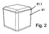
立方体のポーションカプセルを挿入するための挿入開口部7が図1および図3にはっきりと見える。このような立方体の一例である、略立方体形状部カプセル51を図2に示す。カプセル51は、特許出願PCT/CH2010/000097に詳細に記載されている種類のカプセルである。この特許出願PCT/CH2010/000097は、プラスチック壁を有するこのようなカプセルの性質に関して、およびその製造に関して言及され、好ましくはカプセルは、突出端縁が溶接と同時に分離される方法で閉じられる。図2には、特徴的なカプセル形状とは別に、上記方法によって立上がり、かつカプセルの付加的な剛性部として作用し得る周囲溶接端51.1も見える。 The
本発明に係る抽出装置の実施例は、プラスチック製のカプセルに特に適合されている。これに関して特に好ましいカプセルの材料の1つはポリプロピレン(PP)である。他の材料、特に他の食品適合プラスチックも考えられる。プラスチックカプセルとしての、特にポリプロピレンカプセルとしての設計における壁の厚みは、好ましくは0.1mm〜0.5mmであり、たとえば0.2mm〜0.4mmであり、特に0.25mm〜0.35mmである。 The embodiment of the extraction device according to the invention is particularly adapted to plastic capsules. One particularly preferred capsule material in this regard is polypropylene (PP). Other materials, especially other food compatible plastics, are also conceivable. The wall thickness in the design as a plastic capsule, in particular as a polypropylene capsule, is preferably 0.1 mm to 0.5 mm, for example 0.2 mm to 0.4 mm, in particular 0.25 mm to 0.35 mm. .
挿入開口部7は構造内に設計され、放出装置3の領域内に配置され、この装置と同様に、操作レバー5の移動の時に静止し続ける。挿入開口部7は、カプセルが大きくなりすぎて詰まる危険を伴わずに、挿入時にカプセル51に対するセンタリング効果を生じさせるために、底部に向かってやや円錐形状に先細りし得る。 The
操作状態では、醸造モジュールはコーヒーマシンの醸造モジュールとして作用する。図3に概略的に示される、醸造モジュールを有する本発明に係るコーヒーマシンは、醸造モジュールとは別に、水タンク71と、導入装置4に醸造水を提供するポンプ72と、水加熱装置73(たとえば温水器)とを含む。醸造工程後にカプセル51が落下するか運ばれてくるカプセル容器75が、醸造モジュールの下方に配置される。 In operation, the brew module acts as a brew module for the coffee machine. A coffee machine according to the present invention having a brewing module schematically shown in FIG. 3 includes, separately from the brewing module, a water tank 71, a
導入装置4への熱湯の供給は、可撓性を有する導水管部(可撓性管)を介して、および供給通路18を介して行われる。導入装置はさらに、割当てられた提供開口部を有する少なくとも1つの穿刺先端12を含むため、カプセルを穿刺して、抽出液とともに提供開口部から供給することができる。コーヒーマシンはさらに、たとえばカプセル容器75を含み、カプセル容器75は醸造チャンバの下方に配置され、醸造工程の後、操作レバー5を持上げることによってカプセルがカプセル容器75内に自動的に排出される。 Hot water is supplied to the introduction device 4 through a flexible water conduit (flexible tube) and through a
放出装置3にはまた、少なくとも1つの穿刺先端11と、割当てられた放出開口部とが設けられている。さらに、構造によっては放出管もあり、これによって、放出装置の出口8から出てくるコーヒー(など)が、意図された位置に置かれたカップ78に滴り落ちるように導かれる。 The
放出装置3の穿刺先端11は抽出側封止材61に囲まれ、導入装置4の穿刺先端は注入側封止材62に囲まれる。これらの封止材は、以下により詳細に説明する。ワイパー要素15も同様に示され、この機能も同様に以下に説明する。 The
穿刺先端、およびこれらが固定される要素は、ここで明確に言及される上記の特許出願PCT/CH2010/000098に従って設計され得る。 The piercing tips and the elements to which they are secured can be designed according to the above-mentioned patent application PCT / CH2010 / 000098, which is specifically mentioned here.
醸造チャンバを開けたときに(図1)挿入開口部7から挿入される略立方体形状のカプセル51は、放出装置3の支持部16および可動カプセル支持部19によって支持されるように醸造モジュール内に保持される。 When the brewing chamber is opened (FIG. 1), the substantially
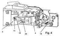
図4は醸造モジュールの変形例を示し、開いた醸造チャンバに挿入される略立方体形状のカプセル51は醸造チャンバの支持部20によって支持され、当該支持部は、側壁14と、放出装置の穿刺先端11を含む放出装置3の端面と、導入装置4の要素とともに、醸造チャンバを形成する。図4の醸造モジュールは、封止システムを除いて、特許出願PCT/CH2010/000099に記載の醸造モジュールに対応し、当該出願の教示内容は本明細書中に明確に援用される。FIG. 4 shows a variant of the brewing module, in which a substantially
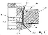
図5は、概略的に示されるカプセル51が取付けられた図4の醸造モジュールの放出装置の断面を示す。封止材61がはっきりと見え、図6にも示される。封止材61は、カプセル51の面側を圧迫する、内向きに突出する周囲封止口縁61.1を含む。さらなる封止工程としての封止ビード61.2がカプセルの周囲面に沿って圧迫する。示される実施例では、封止ビード61.2の領域内の封止材は、封止ビード61.2の領域内の封止材の弾性を増大させる任意の外側ノッチ61.3を含む。封止口縁と封止ビードとの間、したがってカプセルの丸まった端縁の領域に、顕著なトラフ61.4が形成され、カプセルを放出装置に強く押付けることによって、このトラフは封止口縁61.1、封止ビード61.2とカプセル51との間に空隙を形成する。封止フランジ61.5は醸造モジュール内の固定の役割を果たす。 FIG. 5 shows a cross section of the discharge device of the brewing module of FIG. 4 with the
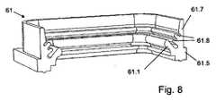
放出装置用の封止材のさらなる実施例を図7および図8に示す。この封止材は、図1の醸造モジュールの放出装置3の封止材に対応する。先に説明した封止材と同様に、この封止材61は、カプセル51を取囲む封止鍔61.7をさらに含む。封止鍔61.7に近接して鍔を有し、内向きに突出し、カプセル51の端面を圧迫する(第1の)封止口縁61.1に加えて、封止材61は、カプセルの端縁の領域においてカプセルを圧迫する、2つのさらなる封止口縁61.8を含む。特に、封止口縁61.8は、剛性溶接端51.1の両側に存在するように配置され得、これによって特に良好な安定および封止効果が得られる。 A further embodiment of a sealing material for the discharge device is shown in FIGS. This sealing material corresponds to the sealing material of the
図1の醸造モジュールの注入側封止材62をさらに図9および図10に示す。カプセルの端面を圧迫する内向きに突出する第1の封止口縁62.1に加えて、複数の第2の取囲み封止口縁62.9が封止鍔62.7上にある。示される実施例では、このような封止口縁62.9は4つあり、他の実施例では、2つ、3つ、5つまたはそれよりも多いそのような(もしくは他の)封止口縁がある。好ましくは、当該数は2〜5個であり、特に3〜5個である。抽出側封止材61と同様に、示される実施例の注入側封止材62も固定フランジ62.5をさらに含む。 The injection
第2の封止口縁は、抽出側封止材61の第1の封止口縁61.1およびさらなる封止口縁61.8とは対照的に、自身の幾何学的形状のために比較的高い剛性を有し、これによって、比較的大きい弾力を、そのような力が外側から圧迫することなしに、取囲まれたカプセルに及ぼしてカプセルを保持することができる。示される実施例では、第2の封止口縁は、遠位の(すなわち醸造液が注入される方向から離れて)突出口縁後部62.10を有する鋸歯状である。この形状は同様に、略垂直面62.11に対する近位側からの醸造液の圧力が、封止口縁をカプセル壁にさらに強く押付ける効果を有する。第1の封止口縁62.1と同様に断面がやや翼状である傾向がある内向きに突出する口縁とは対照的に、鋸歯形状は上記の剛性をもたらす。 The second sealing lip is due to its own geometric shape, in contrast to the first sealing lip 61.1 and the further sealing lip 61.8 of the extraction
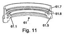
いずれの場合も、非立方体であるが円筒形の、たる形状またはビーカー形状のカプセルに適用可能な抽出側封止材61および注入側封止材62を図11および図12に示す。図面には、図8および図10とは対照的にカプセル軸に対して回転対称な形状がはっきりと見える。 In any case, FIGS. 11 and 12 show an extraction
本発明に係る抽出材料の実施例は、注入側封止材62が醸造チャンバの開口部にカプセルを保持し、カプセルを抽出側穿刺先端から、および抽出側の取囲み封止材61から引抜いて、使用後にカプセルがカプセル容器75に落下するように設計される。これは図13〜図15に示される。 In the embodiment of the extraction material according to the present invention, the injection
図1は、カプセルが挿入されていない醸造モジュールの当初の位置を示す。図13ではカプセル51が挿入開口部7から挿入されて、放出装置3の可動カプセル支持部19および支持部16上に載っている。その後、操作レバー5を動かすことによって導入装置4をカプセル51および放出装置3まで変位させ、これによって注入側封止材62がカプセル上へ押され、カプセルが放出装置に押付けられて注入側および抽出側で穿刺される。醸造チャンバを閉じる相対移動によって、カプセルが注入側封止材に取囲まれてこれによって所定の位置に保持されるとすぐに、カプセル支持部もカプセルから離れるように変位させることができる。醸造プロセスは醸造チャンバを閉じた後に行われ、醸造プロセスでは、醸造液が加圧下でカプセルに導入され、醸造飲物が抽出側でカプセルから放出される。 FIG. 1 shows the initial position of the brewing module with no capsule inserted. In FIG. 13, the
図14は、導入装置と放出装置との相対移動の初めにおける、カプセル51が取付けられた醸造モジュールを示し、この相対移動によって醸造モジュールが開き、操作レバーの枢動運動によってこの相対移動がふたたび行われる。注入側封止材62はカプセルを保持し、抽出側穿刺先端11および抽出側封止材61からカプセルを引抜く。図14の位置から図15の位置の方向における右側へさらに移動を続けると、カプセルがワイパー手段15によって把持され、移動し続ける導入装置に対するカプセルの相対移動が阻止され、これによってカプセルも注入側封止材62から引抜かれる。カプセル支持部19は当初の位置から変位するため、カプセルはカプセル容器75に下向きに落下し得る。図15は、カプセル支持部19が変位して当初の位置に戻る前の、醸造チャンバが開けられた状態を示す。FIG. 14 shows the brewing module with the
示される実施例では、醸造モジュールは「水平醸造モジュール」型である。しかし、他の実施例も可能である。特に、抽出装置は、醸造チャンバを形成するために、抽出装置の静止部に固定可能なピストンに放出装置または場合によっては導入装置が一体化された「ピストンマシン」型であってもよい。 In the example shown, the brewing module is of the “horizontal brewing module” type. However, other embodiments are possible. In particular, the extraction device may be of the “piston machine” type in which a discharge device or possibly an introduction device is integrated into a piston that can be fixed to the stationary part of the extraction device to form a brewing chamber.
Claims (15)
Translated fromJapanese前記醸造モジュールは、第1の醸造モジュール部と、前記第1の醸造モジュール部と相対移動可能な第2の醸造モジュール部とを含み、前記第1および第2の醸造モジュール部は、前記カプセルから抽出製品を放出するための放出装置と、前記カプセルに抽出液を導入するための導入装置とを形成し、
前記導入装置は、前記カプセルを穿刺するための少なくとも1つの穿刺先端を含み、前記導入装置には、弾性変形可能な注入側封止材が設けられ、前記注入側封止材は、前記導入装置の前記少なくとも1つの前記穿刺先端を囲み、前記注入側封止材は、前記カプセルを取囲むとともに前記カプセルを位置決めして保持する封止鍔と、少なくとも1つの周囲封止口縁とを含み、
前記少なくとも1つの注入側封止口縁は、前記カプセルの表面を線状または一片状に圧迫し、前記カプセル壁を前記カプセル内部に押付け、
前記少なくとも1つの注入側封止口縁は前記抽出液の注入位置に向けて内向きに突出し、それにより前記抽出液の液圧が前記少なくとも1つの注入側封止口縁を前記カプセルにさらに押付ける、抽出装置。A Ru extraction device comprisinga brewingmodule for receivinga capsuleLe and amosquito capsule walland mosquito capsule inside the brewing material,
Before SL brewingmodule has a first brewing module part, and a first brewing module part relative movable second brewing module part, wherein the first and second brewing module part, whereinand releaseequipment for releasing the extracted product from the capsule,and introducingequipment for introducing an extraction liquid into the capsule to form,
Prior Symbol introduction device comprisesat least one puncture destinationend for puncturing thecapsule, before Symbol introductionequipment, elastically deformable injection side sealingmember is provided, wherein the injection side sealing material , surroundingthe at leastone of said puncture destinationend of the introduction device,the injection-side sealing member comprisesasealingflangethat Soocoercive by positioningthe capsule together surrounding the capsule, at least one peripheral sealing Including a stopedge ,
Before SL least oneinjection side Futomeguchien is to compress the surface of the capsule to linear or piece-like, pushing the capsule wall inside thecapsule,
Wherein the at least oneinjection-side Futomeguchien projecting inwardly toward the NoteIrii location of the extract, therebythe hydraulic pressure of the extraction liquid is at least oneinjection-side sealinginlet edge to the capsule Further pressing, extraction device.
前記第1の注入側封止口縁は、前記第2の注入側封止口縁よりも、前記抽出液が注入される近位側に位置し、The first injection-side sealing port edge is located closer to the proximal side where the extract is injected than the second injection-side sealing port edge,
前記第1の注入側封止口縁は、前記第2の注入側封止口縁よりも前記抽出液の注入位置に向けて内向きに突出する、請求項1〜4のいずれか一項に記載の抽出装置。The first injection-side sealing port edge protrudes inwardly toward the extraction liquid injection position from the second injection-side sealing port edge, according to any one of claims 1 to 4. The extraction device described.
前記少なくとも1つの注入側封止口縁は、カプセル内部に受けられる抽出材料を含むカプセルの表面を線状または一片状に圧迫し、前記カプセル壁を前記カプセル内部に押付け、
前記少なくとも1つの注入側封止口縁は前記抽出液の注入位置に向けて内向きに突出し、それにより前記抽出液の液圧が前記少なくとも1つの注入側封止口縁を前記カプセルにさらに押付け、
前記注入側封止材は前記カプセルを位置決めして保持する、注入側封止材。Ainjection side sealingmember for the extraction device according to any one of claims 1 to13 comprisingat least one peripheralinjection side Futomeguchiedge,
Before SL least oneinjection side Futomeguchien is to compress the surfaceof the capsuleLe comprising an extract material which is received within the capsule to linear or piece-like, pressing the capsule wall inside the capsule,
Wherein the at least oneinjection-side Futomeguchien projecting inwardly toward the NoteIrii location of the extract, therebythe hydraulic pressure of the extraction liquid is at least oneinjection-side sealinginlet edge to the capsule furtherpressing,
The injection-side sealing material is an injection-side sealing material that positions and holds the capsule .
Applications Claiming Priority (1)
| Application Number | Priority Date | Filing Date | Title |
|---|---|---|---|
| PCT/CH2010/000249WO2012045184A1 (en) | 2010-10-08 | 2010-10-08 | Extraction device and sealing system |
Publications (2)
| Publication Number | Publication Date |
|---|---|
| JP2013542007A JP2013542007A (en) | 2013-11-21 |
| JP5796852B2true JP5796852B2 (en) | 2015-10-21 |
Family
ID=43902712
Family Applications (1)
| Application Number | Title | Priority Date | Filing Date |
|---|---|---|---|
| JP2013532021AActiveJP5796852B2 (en) | 2010-10-08 | 2010-10-08 | Extraction device and sealing system |
Country Status (14)
| Country | Link |
|---|---|
| US (1) | US9068652B2 (en) |
| EP (1) | EP2624731B8 (en) |
| JP (1) | JP5796852B2 (en) |
| KR (1) | KR101812833B1 (en) |
| CN (1) | CN103298380B (en) |
| AU (1) | AU2010362186B2 (en) |
| BR (1) | BR112013008363B1 (en) |
| CA (1) | CA2813460C (en) |
| DK (1) | DK2624731T3 (en) |
| ES (1) | ES2553764T3 (en) |
| PL (1) | PL2624731T3 (en) |
| PT (1) | PT2624731E (en) |
| RU (1) | RU2541946C2 (en) |
| WO (1) | WO2012045184A1 (en) |
Families Citing this family (35)
| Publication number | Priority date | Publication date | Assignee | Title |
|---|---|---|---|---|
| PL2806773T3 (en)* | 2012-01-25 | 2017-02-28 | Qbo Coffee Gmbh | Brewing module |
| US9255654B2 (en)* | 2012-09-14 | 2016-02-09 | United Technologies Corporation | Hard lead egress adapter for an instrumentation component |
| EP2856917A1 (en)* | 2013-10-01 | 2015-04-08 | Luna Technology Systems LTS GmbH | Brewing module |
| ES2572682T3 (en)* | 2013-12-24 | 2016-06-01 | Qbo Coffee Gmbh | Ration capsules for the preparation of a scalded product and procedure for its manufacture |
| EP3089639B1 (en) | 2014-01-03 | 2018-07-11 | Koninklijke Douwe Egberts B.V. | Exchangeable supply pack for a beverage dispensing machine, doser, pump assembly and method of manufacturing. |
| CN107405019B (en)* | 2014-11-06 | 2019-09-20 | 路易吉·拉瓦扎股份公司 | For preparing the machine of liquid product by capsule |
| EP3028608A1 (en)* | 2014-12-01 | 2016-06-08 | Qbo Coffee GmbH | Brewing module, capsule sensing module and machine for preparing beverages |
| NL2016781B1 (en) | 2015-05-15 | 2016-12-30 | Douwe Egberts Bv | A capsule, a system for preparing a potable beverage from such a capsule and use of such a capsule in a beverage preparation device |
| ES2743219T3 (en) | 2015-05-15 | 2020-02-18 | Douwe Egberts Bv | A capsule, a system for preparing a drinkable beverage from said capsule and use of said capsule in a beverage preparation device |
| DK3134332T3 (en) | 2015-05-15 | 2019-08-26 | Douwe Egberts Bv | COVER, SYSTEM FOR PREPARING A DRINKABLE BEVERAGE FROM SUCH A COVER AND USING SUCH A COVER IN A BEVERAGE COOKING DEVICE |
| ES2690990T3 (en) | 2015-05-15 | 2018-11-23 | Koninklijke Douwe Egberts B.V. | A capsule, a system for preparing a drinkable beverage from said capsule and use of said capsule in a beverage preparation device |
| AU2016264690A1 (en) | 2015-05-15 | 2017-12-14 | Koninklijke Douwe Egberts B.V. | A capsule, a system for preparing a potable beverage from such a capsule and use of such a capsule in a beverage preparation device |
| EP3566977B2 (en) | 2015-05-15 | 2025-07-09 | Koninklijke Douwe Egberts B.V. | A capsule, a system for preparing a potable beverage from such a capsule and use of such a capsule in a beverage preparation device |
| AU2016346005B2 (en) | 2015-10-27 | 2022-05-19 | Koninklijke Douwe Egberts B.V. | Capsule, system and method for preparing a beverage |
| PT109303B (en)* | 2016-04-07 | 2021-02-15 | Novadelta Comercio Ind Cafes Sa | EXTRACTION DEVICE WITH MOBILE CAPSULE SUPPORT |
| NL2016779B1 (en) | 2016-05-13 | 2017-11-16 | Douwe Egberts Bv | A capsule and a system for preparing a potable beverage from such a capsule |
| NL2016780B1 (en) | 2016-05-13 | 2017-11-16 | Douwe Egberts Bv | A capsule, a system for preparing a potable beverage from such a capsule and use of such a capsule in a beverage preparation device |
| NL2017277B1 (en) | 2016-08-03 | 2018-02-14 | Douwe Egberts Bv | Apparatus and method for preparing a beverage and system comprising the apparatus and an exchangeable capsule |
| NL2017285B1 (en) | 2016-08-03 | 2018-02-14 | Douwe Egberts Bv | System, apparatus, method, capsule and kit of capsules for preparing a beverage |
| NL2017278B1 (en) | 2016-08-03 | 2018-02-14 | Douwe Egberts Bv | System, apparatus, method, capsule and kit of capsules for preparing a beverage |
| NL2017281B1 (en) | 2016-08-03 | 2018-02-14 | Douwe Egberts Bv | System for preparing a beverage |
| NL2017284B1 (en) | 2016-08-03 | 2018-02-14 | Douwe Egberts Bv | System and method for preparing a beverage field and background |
| NL2017279B1 (en) | 2016-08-03 | 2018-02-14 | Douwe Egberts Bv | System for preparing a beverage |
| NL2017283B1 (en) | 2016-08-03 | 2018-02-14 | Douwe Egberts Bv | System and apparatus for preparing a beverage |
| NL2017280B1 (en) | 2016-08-03 | 2018-02-14 | Douwe Egberts Bv | System for preparing a beverage |
| NL2019218B1 (en) | 2016-08-03 | 2018-07-06 | Douwe Egberts Bv | Capsule, system and use of the system for preparing double beverages like a double espresso, a double lungo and a double ristretto |
| NL2017282B1 (en) | 2016-08-03 | 2018-02-14 | Douwe Egberts Bv | System for preparing a beverage |
| CH712822A1 (en)* | 2016-08-17 | 2018-02-28 | Delica Ag | Device for preparing a beverage. |
| NL2019254B9 (en) | 2016-10-07 | 2018-09-10 | Douwe Egberts Bv | A capsule, a system for preparing a potable beverage from such a capsule and use of such a capsule in a beverage preparation device |
| NL2017587B1 (en) | 2016-10-07 | 2018-04-16 | Douwe Egberts Bv | Capsule, system and method for preparing a beverage |
| DE102017112903A1 (en)* | 2017-06-12 | 2018-12-13 | Vorwerk & Co. Interholding Gmbh | Tea strainer with sealing element and system with such a tea strainer insert |
| NL2019253B1 (en) | 2017-07-14 | 2019-01-28 | Douwe Egberts Bv | Assembly of a capsule and a brew chamber, brew chamber, beverage preparation machine, capsule and use of a capsule. |
| NL2022190B1 (en) | 2018-12-12 | 2020-07-03 | Douwe Egberts Bv | Air purge groove |
| CN116867402A (en)* | 2021-02-09 | 2023-10-10 | 埃维韦公司 | Beverage system |
| WO2023170084A1 (en)* | 2022-03-07 | 2023-09-14 | Société des Produits Nestlé S.A. | Beverage preparation system |
Family Cites Families (21)
| Publication number | Priority date | Publication date | Assignee | Title |
|---|---|---|---|---|
| US2209235A (en)* | 1938-06-29 | 1940-07-23 | Goodrich Co B F | Pipe joint assembly |
| GB1083451A (en)* | 1963-03-11 | 1967-09-13 | Allied Ironfounders Ltd | A sealing member and a pipe joint incorporating the same |
| JPH0358232A (en) | 1989-07-27 | 1991-03-13 | Mitsubishi Electric Corp | Preprocessor calling system |
| JPH0713616Y2 (en)* | 1989-10-09 | 1995-04-05 | ラッキーコーヒーマシン株式会社 | Beverage extractor raw material cartridge receiving |
| ATE128614T1 (en)* | 1990-07-27 | 1995-10-15 | Nestle Sa | BREWING DEVICE FOR CLOSED PORTION PACKS. |
| TWI236360B (en) | 2000-06-30 | 2005-07-21 | Nestle Sa | Capsule cage |
| JP2002188725A (en) | 2000-12-20 | 2002-07-05 | Kobe Steel Ltd | Packing with lip |
| ATE249777T1 (en)* | 2000-12-29 | 2003-10-15 | Sgl Italia Srl | COFFEE MACHINE |
| ITTO20010902A1 (en)* | 2001-09-21 | 2003-03-21 | Sgl Italia Srl | COFFEE MACHINE'. |
| GB2382976B (en)* | 2001-12-11 | 2005-07-20 | Mars Inc | Beverage brewing method and apparatus |
| EP1549186A1 (en)* | 2002-09-20 | 2005-07-06 | Nestec S.A. | Method, device, and capsule for preparing a foamy liquid food |
| DE60303320T2 (en)* | 2003-02-07 | 2006-09-21 | Nestec S.A. | Linear extraction module for preparing a beverage from a cartridge |
| DK1702543T3 (en)* | 2004-10-25 | 2008-01-07 | Nestec Sa | Capsule with sealants |
| FR2904205B1 (en)* | 2006-07-26 | 2012-04-06 | Cie Mediterraneenne Des Cafes | DEVICE AND METHOD FOR PRODUCING BEVERAGES BY INFUSION |
| AU2007302077A1 (en)* | 2006-09-26 | 2008-04-03 | Nestec S.A. | Extraction system for the preparation of a beverage from a cartridge |
| FR2908970A1 (en)* | 2006-11-28 | 2008-05-30 | Rolland Versini | Spherical disposable capsule for automatic beverage preparing and distributing machine, has conditioning envelope presenting spherical external shape to be pierced on any part of evelop's surface |
| ITFI20070028A1 (en)* | 2007-02-07 | 2008-08-08 | Saeco Ipr Ltd | INFUSION DEVICE FOR THE PREPARATION OF DRINKS FROM SINGLE-DOSE CAPSULES WITH A CAPSULES CENTERING DEVICE. |
| EP2316311B1 (en) | 2008-01-15 | 2013-12-04 | Nestec S.A. | Sealing adapter for a beverage extraction system suitable for preparing a beverage from cartridges |
| PT2142054E (en)* | 2008-03-20 | 2011-01-24 | Nestec Sa | Beverage production device for producing a beverage from a single-use capsule |
| IT1392572B1 (en)* | 2008-12-30 | 2012-03-09 | Lavazza Luigi Spa | INFUSION GROUP FOR A DRINK PREPARATION MACHINE |
| WO2010092543A2 (en) | 2009-02-11 | 2010-08-19 | Ethical Coffee Company Sa | Device for preparing a beverage extracted from a capsule |
- 2010
- 2010-10-08JPJP2013532021Apatent/JP5796852B2/enactiveActive
- 2010-10-08USUS13/877,666patent/US9068652B2/enactiveActive
- 2010-10-08PTPT107716250Tpatent/PT2624731E/enunknown
- 2010-10-08AUAU2010362186Apatent/AU2010362186B2/ennot_activeCeased
- 2010-10-08EPEP10771625.0Apatent/EP2624731B8/enactiveActive
- 2010-10-08ESES10771625.0Tpatent/ES2553764T3/enactiveActive
- 2010-10-08CNCN201080069482.6Apatent/CN103298380B/enactiveActive
- 2010-10-08WOPCT/CH2010/000249patent/WO2012045184A1/enactiveApplication Filing
- 2010-10-08BRBR112013008363-8Apatent/BR112013008363B1/enactiveIP Right Grant
- 2010-10-08KRKR1020137011553Apatent/KR101812833B1/enactiveActive
- 2010-10-08RURU2013119877/12Apatent/RU2541946C2/enactive
- 2010-10-08DKDK10771625.0Tpatent/DK2624731T3/enactive
- 2010-10-08PLPL10771625Tpatent/PL2624731T3/enunknown
- 2010-10-08CACA2813460Apatent/CA2813460C/ennot_activeExpired - Fee Related
Also Published As
| Publication number | Publication date |
|---|---|
| RU2013119877A (en) | 2014-11-20 |
| AU2010362186B2 (en) | 2016-10-27 |
| US9068652B2 (en) | 2015-06-30 |
| US20130220138A1 (en) | 2013-08-29 |
| KR101812833B1 (en) | 2017-12-27 |
| PT2624731E (en) | 2015-12-07 |
| PL2624731T3 (en) | 2016-01-29 |
| BR112013008363B1 (en) | 2020-10-27 |
| HK1187505A1 (en) | 2014-04-11 |
| AU2010362186A1 (en) | 2013-05-02 |
| BR112013008363A8 (en) | 2018-10-23 |
| CA2813460C (en) | 2017-08-22 |
| DK2624731T3 (en) | 2015-11-30 |
| CA2813460A1 (en) | 2012-04-12 |
| EP2624731B8 (en) | 2015-10-14 |
| KR20140037010A (en) | 2014-03-26 |
| EP2624731A1 (en) | 2013-08-14 |
| JP2013542007A (en) | 2013-11-21 |
| BR112013008363A2 (en) | 2016-06-14 |
| RU2541946C2 (en) | 2015-02-20 |
| CN103298380B (en) | 2016-08-03 |
| ES2553764T3 (en) | 2015-12-11 |
| CN103298380A (en) | 2013-09-11 |
| WO2012045184A1 (en) | 2012-04-12 |
| EP2624731B1 (en) | 2015-09-02 |
Similar Documents
| Publication | Publication Date | Title |
|---|---|---|
| JP5796852B2 (en) | Extraction device and sealing system | |
| US10244887B2 (en) | Capsule for an extraction material, method for producing the capsule, and device for brewing coffee | |
| AU2013243206B2 (en) | Method and preparation system for preparing a brewed product | |
| US20120272830A1 (en) | Device for preparing a beverage and capsule | |
| JP4083123B2 (en) | Beverage extraction method and apparatus | |
| TW201002254A (en) | Beverage production device for producing a beverage from a single-use capsule | |
| JP6720081B2 (en) | System for preparing extracted products | |
| AU2010261809A1 (en) | Opening means for a capsule-based beverage preparation device | |
| US11230431B2 (en) | Capsule for preparing infusion beverages |
Legal Events
| Date | Code | Title | Description |
|---|---|---|---|
| A977 | Report on retrieval | Free format text:JAPANESE INTERMEDIATE CODE: A971007 Effective date:20140818 | |
| A131 | Notification of reasons for refusal | Free format text:JAPANESE INTERMEDIATE CODE: A131 Effective date:20140826 | |
| A601 | Written request for extension of time | Free format text:JAPANESE INTERMEDIATE CODE: A601 Effective date:20141125 | |
| A602 | Written permission of extension of time | Free format text:JAPANESE INTERMEDIATE CODE: A602 Effective date:20141202 | |
| A601 | Written request for extension of time | Free format text:JAPANESE INTERMEDIATE CODE: A601 Effective date:20141225 | |
| A521 | Request for written amendment filed | Free format text:JAPANESE INTERMEDIATE CODE: A523 Effective date:20150119 | |
| TRDD | Decision of grant or rejection written | ||
| A01 | Written decision to grant a patent or to grant a registration (utility model) | Free format text:JAPANESE INTERMEDIATE CODE: A01 Effective date:20150714 | |
| A61 | First payment of annual fees (during grant procedure) | Free format text:JAPANESE INTERMEDIATE CODE: A61 Effective date:20150812 | |
| R150 | Certificate of patent or registration of utility model | Ref document number:5796852 Country of ref document:JP Free format text:JAPANESE INTERMEDIATE CODE: R150 | |
| R250 | Receipt of annual fees | Free format text:JAPANESE INTERMEDIATE CODE: R250 | |
| R250 | Receipt of annual fees | Free format text:JAPANESE INTERMEDIATE CODE: R250 | |
| R250 | Receipt of annual fees | Free format text:JAPANESE INTERMEDIATE CODE: R250 | |
| R250 | Receipt of annual fees | Free format text:JAPANESE INTERMEDIATE CODE: R250 | |
| R250 | Receipt of annual fees | Free format text:JAPANESE INTERMEDIATE CODE: R250 | |
| R250 | Receipt of annual fees | Free format text:JAPANESE INTERMEDIATE CODE: R250 | |
| R250 | Receipt of annual fees | Free format text:JAPANESE INTERMEDIATE CODE: R250 |