JP5796408B2 - Oral care device - Google Patents
Oral care deviceDownload PDFInfo
- Publication number
- JP5796408B2 JP5796408B2JP2011182263AJP2011182263AJP5796408B2JP 5796408 B2JP5796408 B2JP 5796408B2JP 2011182263 AJP2011182263 AJP 2011182263AJP 2011182263 AJP2011182263 AJP 2011182263AJP 5796408 B2JP5796408 B2JP 5796408B2
- Authority
- JP
- Japan
- Prior art keywords
- unit
- plaque
- care
- site
- brush
- Prior art date
- Legal status (The legal status is an assumption and is not a legal conclusion. Google has not performed a legal analysis and makes no representation as to the accuracy of the status listed.)
- Active
Links
- 238000001514detection methodMethods0.000claimsdescription44
- 238000003384imaging methodMethods0.000claimsdescription36
- 230000033001locomotionEffects0.000claimsdescription30
- 238000006243chemical reactionMethods0.000claimsdescription14
- 210000000214mouthAnatomy0.000claimsdescription11
- 230000001680brushing effectEffects0.000description78
- 238000000034methodMethods0.000description47
- 230000008569processEffects0.000description45
- 230000001133accelerationEffects0.000description41
- 210000000515toothAnatomy0.000description29
- 238000012545processingMethods0.000description16
- 210000004513dentitionAnatomy0.000description10
- 230000036346tooth eruptionEffects0.000description10
- 230000005540biological transmissionEffects0.000description9
- 230000000737periodic effectEffects0.000description9
- 230000008859changeEffects0.000description7
- 238000010586diagramMethods0.000description7
- 239000011347resinSubstances0.000description7
- 229920005989resinPolymers0.000description7
- 230000006870functionEffects0.000description6
- 238000011156evaluationMethods0.000description5
- 239000000463materialSubstances0.000description5
- 210000003254palateAnatomy0.000description5
- 239000000758substrateSubstances0.000description4
- 208000002064Dental PlaqueDiseases0.000description3
- 230000004397blinkingEffects0.000description3
- 229920001971elastomerPolymers0.000description3
- 238000002474experimental methodMethods0.000description3
- WABPQHHGFIMREM-UHFFFAOYSA-Nlead(0)Chemical compound[Pb]WABPQHHGFIMREM-UHFFFAOYSA-N0.000description3
- 210000004373mandibleAnatomy0.000description3
- 230000003287optical effectEffects0.000description3
- 230000009471actionEffects0.000description2
- 238000004140cleaningMethods0.000description2
- 230000000694effectsEffects0.000description2
- 239000000806elastomerSubstances0.000description2
- 230000005484gravityEffects0.000description2
- 210000001847jawAnatomy0.000description2
- 230000007246mechanismEffects0.000description2
- 230000035945sensitivityEffects0.000description2
- 210000000577adipose tissueAnatomy0.000description1
- 238000013459approachMethods0.000description1
- 210000005178buccal mucosaAnatomy0.000description1
- 238000004891communicationMethods0.000description1
- 230000000295complement effectEffects0.000description1
- 238000012790confirmationMethods0.000description1
- 238000012937correctionMethods0.000description1
- 230000005520electrodynamicsEffects0.000description1
- 230000005674electromagnetic inductionEffects0.000description1
- 238000001914filtrationMethods0.000description1
- 239000010794food wasteSubstances0.000description1
- 238000009499grossingMethods0.000description1
- 210000004283incisorAnatomy0.000description1
- 230000013011matingEffects0.000description1
- 210000002295maxillary toothAnatomy0.000description1
- 238000005259measurementMethods0.000description1
- 239000002184metalSubstances0.000description1
- 229910044991metal oxideInorganic materials0.000description1
- 150000004706metal oxidesChemical class0.000description1
- 238000012986modificationMethods0.000description1
- 230000004048modificationEffects0.000description1
- 239000003973paintSubstances0.000description1
- 230000002093peripheral effectEffects0.000description1
- 238000005498polishingMethods0.000description1
- 239000004065semiconductorSubstances0.000description1
- 239000007921spraySubstances0.000description1
- 239000010409thin filmSubstances0.000description1
- 230000007704transitionEffects0.000description1
- 238000013519translationMethods0.000description1
- 230000014616translationEffects0.000description1
- 230000002087whitening effectEffects0.000description1
- 230000037303wrinklesEffects0.000description1
Images


Classifications
- A—HUMAN NECESSITIES
- A61—MEDICAL OR VETERINARY SCIENCE; HYGIENE
- A61B—DIAGNOSIS; SURGERY; IDENTIFICATION
- A61B5/00—Measuring for diagnostic purposes; Identification of persons
- A61B5/0059—Measuring for diagnostic purposes; Identification of persons using light, e.g. diagnosis by transillumination, diascopy, fluorescence
- A61B5/0082—Measuring for diagnostic purposes; Identification of persons using light, e.g. diagnosis by transillumination, diascopy, fluorescence adapted for particular medical purposes
- A61B5/0088—Measuring for diagnostic purposes; Identification of persons using light, e.g. diagnosis by transillumination, diascopy, fluorescence adapted for particular medical purposes for oral or dental tissue
- A—HUMAN NECESSITIES
- A46—BRUSHWARE
- A46B—BRUSHES
- A46B15/00—Other brushes; Brushes with additional arrangements
- A46B15/0002—Arrangements for enhancing monitoring or controlling the brushing process
- A46B15/0004—Arrangements for enhancing monitoring or controlling the brushing process with a controlling means
- A46B15/0006—Arrangements for enhancing monitoring or controlling the brushing process with a controlling means with a controlling brush technique device, e.g. stroke movement measuring device
- A—HUMAN NECESSITIES
- A46—BRUSHWARE
- A46B—BRUSHES
- A46B15/00—Other brushes; Brushes with additional arrangements
- A46B15/0002—Arrangements for enhancing monitoring or controlling the brushing process
- A46B15/0016—Arrangements for enhancing monitoring or controlling the brushing process with enhancing means
- A46B15/0034—Arrangements for enhancing monitoring or controlling the brushing process with enhancing means with a source of radiation, e.g. UV, IR, LASER, X-ray for irradiating the teeth and associated surfaces
- A—HUMAN NECESSITIES
- A61—MEDICAL OR VETERINARY SCIENCE; HYGIENE
- A61B—DIAGNOSIS; SURGERY; IDENTIFICATION
- A61B1/00—Instruments for performing medical examinations of the interior of cavities or tubes of the body by visual or photographical inspection, e.g. endoscopes; Illuminating arrangements therefor
- A61B1/24—Instruments for performing medical examinations of the interior of cavities or tubes of the body by visual or photographical inspection, e.g. endoscopes; Illuminating arrangements therefor for the mouth, i.e. stomatoscopes, e.g. with tongue depressors; Instruments for opening or keeping open the mouth
- A—HUMAN NECESSITIES
- A61—MEDICAL OR VETERINARY SCIENCE; HYGIENE
- A61B—DIAGNOSIS; SURGERY; IDENTIFICATION
- A61B5/00—Measuring for diagnostic purposes; Identification of persons
- A61B5/45—For evaluating or diagnosing the musculoskeletal system or teeth
- A61B5/4538—Evaluating a particular part of the muscoloskeletal system or a particular medical condition
- A61B5/4542—Evaluating the mouth, e.g. the jaw
- A61B5/4547—Evaluating teeth
- A—HUMAN NECESSITIES
- A61—MEDICAL OR VETERINARY SCIENCE; HYGIENE
- A61C—DENTISTRY; APPARATUS OR METHODS FOR ORAL OR DENTAL HYGIENE
- A61C17/00—Devices for cleaning, polishing, rinsing or drying teeth, teeth cavities or prostheses; Saliva removers; Dental appliances for receiving spittle
- A61C17/16—Power-driven cleaning or polishing devices
- A61C17/20—Power-driven cleaning or polishing devices using ultrasonics
- A—HUMAN NECESSITIES
- A61—MEDICAL OR VETERINARY SCIENCE; HYGIENE
- A61C—DENTISTRY; APPARATUS OR METHODS FOR ORAL OR DENTAL HYGIENE
- A61C17/00—Devices for cleaning, polishing, rinsing or drying teeth, teeth cavities or prostheses; Saliva removers; Dental appliances for receiving spittle
- A61C17/16—Power-driven cleaning or polishing devices
- A61C17/22—Power-driven cleaning or polishing devices with brushes, cushions, cups, or the like
- A61C17/221—Control arrangements therefor
- A—HUMAN NECESSITIES
- A61—MEDICAL OR VETERINARY SCIENCE; HYGIENE
- A61C—DENTISTRY; APPARATUS OR METHODS FOR ORAL OR DENTAL HYGIENE
- A61C17/00—Devices for cleaning, polishing, rinsing or drying teeth, teeth cavities or prostheses; Saliva removers; Dental appliances for receiving spittle
- A61C17/16—Power-driven cleaning or polishing devices
- A61C17/22—Power-driven cleaning or polishing devices with brushes, cushions, cups, or the like
- A61C17/224—Electrical recharging arrangements
- A—HUMAN NECESSITIES
- A61—MEDICAL OR VETERINARY SCIENCE; HYGIENE
- A61C—DENTISTRY; APPARATUS OR METHODS FOR ORAL OR DENTAL HYGIENE
- A61C17/00—Devices for cleaning, polishing, rinsing or drying teeth, teeth cavities or prostheses; Saliva removers; Dental appliances for receiving spittle
- A61C17/16—Power-driven cleaning or polishing devices
- A61C17/22—Power-driven cleaning or polishing devices with brushes, cushions, cups, or the like
- A61C17/32—Power-driven cleaning or polishing devices with brushes, cushions, cups, or the like reciprocating or oscillating
- A61C17/34—Power-driven cleaning or polishing devices with brushes, cushions, cups, or the like reciprocating or oscillating driven by electric motor
- A61C17/3409—Power-driven cleaning or polishing devices with brushes, cushions, cups, or the like reciprocating or oscillating driven by electric motor characterized by the movement of the brush body
- A61C17/3481—Vibrating brush body, e.g. by using eccentric weights
- A—HUMAN NECESSITIES
- A46—BRUSHWARE
- A46B—BRUSHES
- A46B2200/00—Brushes characterized by their functions, uses or applications
- A46B2200/10—For human or animal care
- A46B2200/1066—Toothbrush for cleaning the teeth or dentures
Landscapes
- Health & Medical Sciences (AREA)
- Life Sciences & Earth Sciences (AREA)
- Dentistry (AREA)
- General Health & Medical Sciences (AREA)
- Veterinary Medicine (AREA)
- Animal Behavior & Ethology (AREA)
- Public Health (AREA)
- Physics & Mathematics (AREA)
- Biophysics (AREA)
- Surgery (AREA)
- Epidemiology (AREA)
- Heart & Thoracic Surgery (AREA)
- Medical Informatics (AREA)
- Molecular Biology (AREA)
- Pathology (AREA)
- Engineering & Computer Science (AREA)
- Biomedical Technology (AREA)
- Oral & Maxillofacial Surgery (AREA)
- Optics & Photonics (AREA)
- Audiology, Speech & Language Pathology (AREA)
- Rheumatology (AREA)
- Physical Education & Sports Medicine (AREA)
- Orthopedic Medicine & Surgery (AREA)
- Nuclear Medicine, Radiotherapy & Molecular Imaging (AREA)
- Radiology & Medical Imaging (AREA)
- Brushes (AREA)
Description
Translated fromJapaneseこの発明は口腔ケア装置に関し、特に、歯の歯垢除去に適用される口腔ケア装置に関する。 The present invention relates to an oral care device, and more particularly to an oral care device applied to dental plaque removal.
従来、歯垢除去に適した振動で動作する電動歯ブラシが提案されていた。電動歯ブラシのユーザには、歯垢がどこに付いているのか、歯磨きで歯垢が落ちたかなど、の情報を提示して欲しいとの要望があった。 Conventionally, an electric toothbrush that operates with vibration suitable for plaque removal has been proposed. Users of electric toothbrushes have been requested to provide information such as where the plaque is attached and whether the plaque has fallen by brushing.
この要望に応えるために、特許文献1(特開2001−145645号公報)と特許文献2(特開2001−170084号公報)では、ビデオスコープと歯ブラシとを一体に備えて、歯磨き動作中に撮影した歯の画像を表示する。 In order to meet this demand, Patent Document 1 (Japanese Patent Application Laid-Open No. 2001-145645) and Patent Document 2 (Japanese Patent Application Laid-Open No. 2001-170084) are provided with a video scope and a toothbrush integrally and photographed during a tooth brushing operation. An image of the tooth that has been removed is displayed.
また、特許文献3(特開2001−218624号公報)では、歯ブラシの刷毛部分に内蔵したカメラでブラッシングしている歯を撮影し、画像を表示する。 Moreover, in patent document 3 (Unexamined-Japanese-Patent No. 2001-218624), the tooth brushing is image | photographed with the camera incorporated in the brush part of the toothbrush, and an image is displayed.
また、特許文献4(特開2008−119154号公報)では、清掃器具で口腔内から除去された付着物を収容し、付着物が除去されていることの確認を促す機能が提案されている。 Patent Document 4 (Japanese Patent Application Laid-Open No. 2008-119154) proposes a function of accommodating deposits removed from the oral cavity with a cleaning tool and prompting confirmation that the deposits have been removed.
また、特許文献5(特表2008−532619号公報)では、センサが受け取った情報に応じて、歯ブラシの出力または動作の調節が可能である。さらに、歯ブラシから光を照射して光化学的作用により光学的美白などを行う構成を記載する。 Moreover, in patent document 5 (Japanese translations of PCT publication No. 2008-532619 gazette), the output or operation | movement of a toothbrush is adjustable according to the information which the sensor received. Furthermore, the structure which irradiates light from a toothbrush and performs optical whitening by a photochemical action is described.
これら文献では、歯ブラシの磨き残し、すなわち歯垢が残っている歯を確認することができない。対して、非特許文献1「Einstein Stella plaque」のホームページ((RF社) http://www.rfsystemlab.com/product/dental/ein_plaque/index.html)および非特許文献2「口腔内カメラ“MIHARU”」のホームページ(http://www.shinwa-musen.co.jp/camera3/miharu.html)では、ワイヤレス口腔内カメラが提案されている。口腔内カメラは、歯垢・レジンだけが反応する所定波長の光を照射し、その反射光を受光し、受光信号を映像信号に変換して映像で出力することで、歯の磨き残しを映像で提供する機能を有する。 In these documents, it is impossible to confirm a toothbrush left unbrushed, that is, a tooth in which plaque remains. In contrast, Non-Patent
非特許文献1と2によれば磨き残しを撮影した映像で確認することができる。しかしながら、磨き残しの歯をブラッシングする場合には、ユーザは撮影した映像のみから、歯列中の磨き残しの部位を推定し、その部位に歯ブラシを当てる必要があるので、撮影映像のみからでは部位を推定するのは困難である。また、撮影映像から磨き残しの歯垢量を把握するのは難しいためブラッシング不足となり歯垢が残ったままになり、または、過度のブラッシングとなり歯の表面が傷む原因ともなる。したがって、口腔内のケアされるべき部位と、当該ケア部位に残る歯垢量を自動的に検出して両者を対応付けて管理する機能の提供が望まれる。 According to
本発明の目的は、口腔のケア部位と、当該ケア部位に対応して検出された歯垢量とを記憶する口腔ケア装置を提供することである。 The objective of this invention is providing the oral-care apparatus which memorize | stores the oral cavity care site | part and the plaque amount detected corresponding to the said care site | part.
この発明に係る口腔ケア装置は、口腔をケアするためのケア部材と、ケア部材の姿勢を検出するための姿勢検出部と、検出された姿勢に基づいて口腔のケア部位を推定するための部位推定部と、歯垢が反応する所定波長の光を出射する光源と、光を受光し電気信号に変換する光電変換部と、光源によりケア部位に対し光を出射させ、ケア部位からの反射光の光電変換部によって変換された電気信号に基づき画像データを取得する撮像部と、撮像部が取得した画像データに基づき、ケア部位の歯垢量を検出するための歯垢検出部と、部位推定部により推定されるケア部位と、当該ケア部位について歯垢検出部により検出される歯垢量とを対応付けてメモリに記憶するための記憶部と、を備える。 An oral care device according to the present invention includes a care member for care of the oral cavity, a posture detection unit for detecting the posture of the care member, and a part for estimating a care part of the oral cavity based on the detected posture An estimation unit, a light source that emits light of a predetermined wavelength to which plaque reacts, a photoelectric conversion unit that receives light and converts it into an electrical signal, and a light source that emits light to the care site, and reflected light from the care site An imaging unit that acquires image data based on the electrical signal converted by the photoelectric conversion unit, a plaque detection unit that detects the amount of plaque in the care site based on the image data acquired by the imaging unit, and site estimation A storage unit for storing the care site estimated by the unit and the plaque amount detected by the plaque detection unit for the care site in association with each other.
本発明によれば、口腔のケア部位と、当該ケア部位の歯垢量を自動的に検出して、両者を対応付けてメモリに記憶し管理することができる。 According to the present invention, the care site of the oral cavity and the amount of plaque in the care site can be automatically detected, and both can be associated with each other and stored and managed in the memory.
以下、この発明の実施の形態について図面を参照しながら説明する。なお、各図中、同一符号は同一または相当部分を指す。 Embodiments of the present invention will be described below with reference to the drawings. In addition, in each figure, the same code | symbol points out the same or an equivalent part.
本実施の形態では、筐体表面に植毛されたブラシを有する電動歯ブラシを説明するが、実施の形態の構成は、口腔ケア(歯の洗浄・ブラッシングなど)に用いることが可能な装置一般に適用することができる。具体的には、口腔ケアに用いる材料としては、歯ブラシに代替してスポンジ、ゴム、エラストマなどの樹脂部品またはブラシとこれら樹脂部品が複合された口腔ケア部材を用いた装置に適用することができる。 In this embodiment, an electric toothbrush having a brush implanted on the surface of a housing will be described. However, the configuration of the embodiment is generally applied to an apparatus that can be used for oral care (tooth cleaning, brushing, etc.). be able to. Specifically, as a material used for oral care, it can be applied to a device using an oral care member in which a resin component such as sponge, rubber, elastomer or the like and a brush and these resin components are combined instead of a toothbrush. .
<構成について>
図1〜図3を参照して、電動歯ブラシの構成を説明する。<About configuration>
The configuration of the electric toothbrush will be described with reference to FIGS.
図1には電動歯ブラシを含むシステムのブロック図を示し、図2には電動歯ブラシの外観を示し、図3には電動歯ブラシの内部構成を示す。 FIG. 1 shows a block diagram of a system including an electric toothbrush, FIG. 2 shows an external appearance of the electric toothbrush, and FIG. 3 shows an internal configuration of the electric toothbrush.
電動歯ブラシ1は、駆動源であるモータ10を内蔵する本体部2と、モータ10の回転に連動して周期的な運動(振動)をする振動源である振動部材5とを備える。したがって、モータ10の回転周期は、電動歯ブラシ本体の振動(運動)の周期に対応する。本体部2は、概ね円柱形状の筐体を有し、筐体の一部は歯を磨く際にユーザが把持する、すなわち手で握るためのハンドル部を兼ねる。 The
さらに、電動歯ブラシ1に関連して、本体部2が載置されて、載置された電動歯ブラシ1を充電するための充電器100と、ブラッシング結果など各種情報を出力するための表示器110とが設けられる。 Furthermore, in relation to the
本体部2は筐体に、ユーザが指示を入力するために操作されて、外部からの操作を受付けるためのスイッチSWを備える。スイッチSWは、電源のオン/オフのためのスイッチ402、後述のモータ10の動作モードの切替えのためのスイッチ、および歯垢の検出開始を指示するためのスイッチ403を含む。 The
また本体部2は筐体内部において、モータ10(たとえば、直流モータ)、駆動回路12、各部に電力を供給するための定格出力2.4Vの電源である充電池13、充電用のコイル14などを有する。充電池13は、充電器100に本体部2を載置するだけで、電磁誘導により非接触で充電される。駆動回路12は、図示されない基板に搭載された各種演算および制御を実行するCPU(Central Processing Unit)120、後述する図7および図23のテーブルTB1およびTB2、プログラムならびに各種設定値が格納されるメモリ121、計時して計時データを出力するタイマ122、データ送信部123などを有する。 Further, the
データ送信部123は、表示器110のデータ受信部112との間で無線通信を行なう。表示器110は、データ受信部112、MPU(Micro Processing Unit)113、およびディスプレイ111を備える。ディスプレイ111は、データ受信部112で受信したブラッシング結果、MPU113の処理結果などの各種データを出力する。 The
さらに、本体部2の内部には、電動歯ブラシ1の姿勢を検知するために、たとえば、多軸(ここではx,y,zの三軸)の加速度センサ15が設けられる。加速度センサ15は、図4に示すように、x軸がブラシ面に対して平行になり、y軸が本体部2の長手方向に一致し、z軸がブラシ面に対して垂直になるように設置される。つまり、本体部2を充電器100に載置したときに、重力加速度ベクトルがy軸に平行になり、ブラシ面を上に向けたときに、重力加速度ベクトルがz軸に平行になり、本体部2を水平にしてブラシ面を横に向けたときに、重力加速度ベクトルがx軸に平行になる。加速度センサ15の各軸の出力はCPU120に入力され、ブラシ210の三次元姿勢を検出するために利用される。 Further, in order to detect the posture of the
加速度センサ15としては、ピエゾ抵抗タイプ、静電容量タイプ、もしくは熱検知タイプのMEMS(Micro Electro Mechanical Systems)センサを好ましく利用できる。MEMSセンサは非常に小型であるため、本体部2の内部への組み込みが容易だからである。ただし、加速度センサ15の形式はこれに限らず、動電式、歪みゲージ式、圧電式などのセンサを利用しても構わない。また特に図示しないが、各軸のセンサの感度のバランス、感度の温度特性、温度ドリフトなどを補正するための補正回路を設けるとよい。また、動加速度成分やノイズを除去するためのバンドパスフィルタ(ローパスフィルタ)を設けてもよい。また、加速度センサの出力波形を平滑化することによりノイズを低減してもよい。 As the
本体部2は、内部に、歯垢が反応する所定波長(405nmの紫外光)の光を出射する光源に相当のLED(Light Emitting Diode)400、および受光し受光量に応じた電気信号に変換して出力する光電変換素子であるCCD(Charge Coupled Device)401を備える。 The
ここで、LED400により口腔内に所定波長の光が照射されると、歯垢またはレジンのみが照射光に反応し、反応によって歯垢またはレジンからは赤色の波長(635nm)の反射光がCCD401に入射する。CCD401は受光し、受光量に応じた電気信号を画像信号として出力する。 Here, when light having a predetermined wavelength is irradiated into the oral cavity by the
ここではPD(Photo Diode)の光電変換素子によるイメージセンサとしてCCD401を用いたが、代替してCMOS(Complementary Metal Oxide Semiconductor)イメージセンサを用いても良い。 Here, the
振動部材5は、本体部2側に固定されているステム部20と、このステム部20に装着されるブラシ部品21とを備える。ブラシ部品21の先端にはブラシ210が植毛されている。ブラシ部品21は消耗部品ゆえ、新品に交換できるよう、ステム部20に対して着脱自在な構成となっている。 The
振動部材5のブラシ部品21は、ブラシ210が配置されたブラシ部3、および、本体部2側に位置する柄部4を含む。なお、本実施形態では、比較的長い柄部4を含むブラシ部品21が取り替えられる構成を示したが、ブラシ部3のみ、あるいは、ブラシ部3および短い柄部を含むブラシ部品が取り替えられる構成であってもよい。つまり、柄部の全てまたは一部は、本体に含まれる構成であってもよい。 The
ステム部20は、樹脂材からなる。ステム部20は、エラストマからなる弾性部材202を介して本体部2に取り付けられている。ステム部20は、先端(ブラシ側の端部)が閉じた筒状の部材であり、筒の内部の先端に軸受203を有している。モータ10の回転軸11に連結された偏心軸30の先端が、ステム部20の軸受203に挿入される。この偏心軸30は、軸受203の近傍に重り300を有しており、偏心軸30の重心はその回転中心からずれている。なお、偏心軸30の先端と軸受203の間には微小なクリアランスが設けられている。 The
電動歯ブラシ1は、さらに、接触または接近の有無を検知するための、電極方式の接触検知部50を備える。接触検知部50は、ブラッシングの際に、生体すなわち頬粘膜および舌との接触または近接を検知する。具体的には、接触検知部50は、電極部52、および、電極部52からのインピーダンスを検出するための検出部54を含む。 The
電極部52は、ブラシ部3の背面側(ブラシ210が取り付けられる面の反対側の面)に配置される電極(以下「背面電極」ともいう)521と、本体部2に配置される電極(以下「本体電極」ともいう)522とを含む。本体電極522は、ブラッシングの際にユーザの手と常時接触するように、本体部2の背面側に設けられることが望ましい。作用反作用の原理により、本体部2の背面に力を加えないといけないからである。本体電極522は、ユーザの指先に合うよう拡張されてもよい。検出部54は、駆動回路12内に搭載されてよい。 The
背面電極521および本体電極522は、導電樹脂素材を採用し、取り付け部の部材と一体的に成型されてもよい。この構造によると、部材間に隙間がないため、防水性が容易に確保でき、汚れの付着も軽減できる。あるいは、金属シートにより形成されてもよいし、スプレー塗料により薄膜形成されてもよい。また、これらの電極521,522には、表面積を増やすために、凹凸を設けてもよい。凹凸を設けることで滑り止めの効果も生じる。凹凸の形状は問わない。 The
図3に示されるように、背面電極521は、取り替え可能なブラシ部品21の内部に形成された電極61、および、ブラシ部品21の端部(本体部2との接触面)に露出された接点電極62と一体形成されている。接点電極62は、本体部2側と背面電極521との電気的接続のための端子として機能する。本体部2の端面(ブラシ部品21と接続される側)には、接点電極63が設けられている。接点電極63は、駆動回路(基板)12とリード線64により電気的に接続されている。本体電極522は、駆動回路(基板)12とリード線65によって電気的に接続されている。 As shown in FIG. 3, the
図1に示した電極部52には、図2に示した背面電極521と本体電極522とを電気的に接続するためのこれらの電気部品(電極61,62,63およびリード線64,65)も含まれる。駆動回路12内の検出部54は、電極部52の電気回路を流れている電流を検出することで、インピーダンスを検出することができる。 In the
また、図1のLED400の光出射面とCCD401の受光面は、ブラシ210が取り付けられている面の背面であって、背面電極521と同じ面に取り付けられる。LED400の光の出射面およびCCD401の受光面は、図示しない光透過部材で覆われて保護されている。LED400およびCCD401は、図示しないリード線を介してCPU120が搭載される基板の配線パターンに接続される。これにより、CPU120からの信号によってLED400の発光動作が制御され、CCD401の光電変換による電気信号はCPU120に出力される。 The light emitting surface of the
なお、上述のように、ブラシ部3のみまたはその近傍部分のみが取り替えられる構成の場合には、背面電極は、本体側の柄部に取り付けられてもよい。そのようにすることで、電極部の内部構成もより簡略化することができ、かつ、ブラシ部品を取り替える際のコストを抑えることもできる。 As described above, in the case where only the
あるいは、背面電極521およびLED400ならびにCCD401は、ブラシ部品21に対して着脱可能であってもよい。このようにすることで、ブラシ部品21を取り替えても背面電極521およびLED400ならびにCCD401を再利用することができる。 Alternatively, the
なお、本体部2内部の部品や本体部2の材質によっては本体電極522がなくても人体を介した閉ループが構成されることがあり得るため、電極部52に本体電極522が含まれなくてもよい。 Depending on the components inside the
<光学素子の他の配置例>
図2では、LED400およびCCD401は、出射光および受光が刷毛により遮られることがないように、またブラッシングにより除去された歯垢で汚れるのを回避できるようにブラシ210の背面側に装着されるが、装着の位置は背面側に限定されない。<Other arrangement examples of optical elements>
In FIG. 2, the
たとえば、ブラシ210の刷毛は、出射光および受光の波長に該当する波長の光を透過する材料からなる場合には、図5に示すように、ブラシ210の植毛される面側にLED400とCCD401を配置するようにしてもよい。 For example, when the
なお、LED400およびCCD401は、上述のようにケア部材であるブラシ210の近傍に近接して設置されるものに限定されない。円柱形状の本体部2の長手方向の端部であって、ブラシ210が設けられる側とは反対側の端部(図2の端部600を参照)に設けるようにしてもよい。つまり、ブラッシング中のケア部位とは無関係にユーザが口腔内の所望部分を撮像して画像および歯垢量を確認する目的で用いる場合には、端部600などブラシ210とは無関係の位置に設けるようにしてもよい。Note that the
<機能構成>
図6を参照して、電動歯ブラシ1の機能構成について説明する。図6では、CPU120が有する機能が関連する周辺回路・部分と関連付けて示される。図示されるCPU120の機能は、メモリ121に予め格納されたプログラムをCPU120が読出し実行することにより実現されると想定するが、プログラムと回路の組合せで実現されるとしてもよい。<Functional configuration>
The functional configuration of the
電動歯ブラシ1のCPU120は、モータ10に駆動信号を供給する駆動信号供給部580を制御するための駆動制御部500、スイッチSWが操作されたことを検出し、操作されたスイッチに応じた操作信号を出力する操作受付部505、ケア部材であるブラシ210を含むブラシ部3の姿勢を検出するための姿勢検出部510、検出された姿勢に基づいてブラッシング(ケア)部位を推定するための部位推定部520、撮像部530、推定された部位の歯垢量を検出するための歯垢検出部540、推定された部位と、当該部位に対応して検出された歯垢量とをメモリ121のテーブルTB1に格納するための記憶部550、メモリ121からデータを読出すための読出部560、および読出されたデータを表示器110に表示するためにデータ送信部123に出力する表示制御部570と、を備える。 The
撮像部530は、操作受付部505がスイッチ403の操作に基づく操作信号を出力すると、光を出射するようにLED400を制御する。出射された光の口腔内での反射光はCCD401により受光されて、光電変換することにより得られた画像信号は撮像部530に出力される。撮像部530は、入力する画像信号を雑音除去(フィルタ処理)し階調値に変換することによりデジタルデータである画像データを取得する。このように、LED400から光を出射させ、CCD401の受光による光電変換の画像データを取得するまでの動作を“撮像”と称する。 When the
歯垢検出部540は、撮像による画像データに基づき、ケア部位の歯垢量を検出する。具体的には、画像データの各画素の階調値を、所定閾値と比較する。所定閾値は歯の画像に相当する階調値と、歯垢の画像(赤色)に相当する階調値とを含む。したがって、比較結果に基づき、ケア部位を撮像した画像における歯の領域と歯垢部分の領域との大きさを検出することができる。歯垢検出部540は、歯垢量として((歯垢部分の領域の大きさ/歯の領域の大きさ)×100)(単位:パーセント)を算出する。 The
<電動歯ブラシの駆動原理>
駆動制御部500は動作モードに応じた制御信号を駆動信号供給部580に出力する。駆動信号供給部580は、入力する制御信号に基づく駆動信号(たとえばパルス幅変調信号)を生成し、モータ10に供給する。ここで、制御信号は、駆動信号の周期とDuty(デューティー)比を指示するための信号である。駆動信号供給部580は、制御信号が指示する周期とDuty比に応じた幅のパルスである駆動信号を生成し、モータ10に連続的に与える。モータ10に周期的なパルス信号が連続して与えられることで、モータ10の回転周期が制御される。<Driving principle of electric toothbrush>
The
モータ10の回転軸11は、駆動信号により回転すると、回転軸11の回転に伴って偏心軸30も回転するが、偏心軸30は重心がずれているために回転中心の回りに旋回するような運動を行なう。よって、偏心軸30の先端の動きが軸受203の内壁に伝わり、ステム部20とそれに装着されたブラシ部品21とを高速に周期的に運動(振動)させることができる。つまり、モータ10が、ブラシ210を運動させる駆動源の役割を担い、偏心軸30が、モータ10の出力(回転)を振動源である振動部材5の振動に変換する運動伝達機構(運動変換機構)の役割を担っている。ここでは、モータ10の回転は、これに連動したブラシ210の周期的な運動に変換されて、周期的運動は、ブラシ210の振動による上下・左右の往復運動または回転運動などを含む。 When the
ユーザは、本体部2を手で持ち、高速に運動するブラシ210を歯に当てることで、ブラッシングを行なうことができる。なお、CPU120はタイマ122を用いて継続動作時間を監視しており、所定時間(たとえば2分間)が経過したら自動的にブラシの運動を停止させるようにしてもよい。 The user can perform brushing by holding the
本実施形態の電動歯ブラシ1では、運動伝達機構である偏心軸30が振動部材5に内包され、特に重り300がブラシ210の近傍側に配置されている。よって、ブラシ210の部分を効率的に振動させることができる。その一方で、振動部材5(ステム部20)が弾性部材202を介して本体部2に取り付けられているので、振動部材5の振動が本体部2に伝わり難くなっている。よって、歯を磨く際の本体部2および手の振動を低減でき、使用感の向上を図ることができる。 In the
<電動歯ブラシの動作>
歯の種類(上顎/下顎、臼歯/切歯など)や部分(舌側/頬側、歯面/噛み合わせ面など)によって、食物残渣や歯垢の付き方が異なる。よって、磨き残しの歯垢は、歯列の部位ごとに相違する。それゆえ、適切なブラッシングが行われているかどうかの評価値ともなる歯垢量の評価は、部位ごとに行なうことが望ましい。<Operation of electric toothbrush>
Depending on the type of teeth (maxillary / mandibular, molar / incisor, etc.) and parts (lingual / buccal, tooth surface / mating surface, etc.), the way food residue and plaque are attached varies. Therefore, the unpolished plaque is different for each part of the dentition. Therefore, it is desirable toevaluate the amountof plaque, which is an evaluation value as to whether or not appropriate brushing is performed, for each part.
そこで、本実施形態の電動歯ブラシ1は、加速度センサ15で検出されたブラシの姿勢(姿勢情報)、および、接触検知部50の検知結果に基づいて、ブラッシング部位を推定する。そして、歯垢検出部540は、推定された部位ごとの歯垢量を検知する。記憶部550によって、ブラッシングの日時と、推定される部位と、当該部位に対応して検出された歯垢量とが対応付けされてメモリ121のテーブルTB1に格納される。 Therefore, the
図7は、部位毎の歯垢量を格納するテーブルTB1の一例を示す図である。図7を参照して、テーブルTB1には、推定される各部位に対応して歯垢検出部540により検出された歯垢量と、検出された日時とが対応付けて格納される。日時は、タイマ122からの計時データに基づき取得される。 FIG. 7 is a diagram illustrating an example of a table TB1 that stores the amount of plaque for each part. Referring to FIG. 7, table TB1 stores the amount of plaque detected by
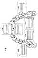
ブラッシングの部位について説明する。本実施形態では、図8に示すように、上下の歯列を、「上顎前頬側」、「上顎前舌側」、「上顎左頬側」、「上顎左舌側」、「上顎右頬側」、「上顎右舌側」、「下顎前頬側」、「下顎前舌側」、「下顎左頬側」、「下顎左舌側」、「下顎右頬側」、「下顎右舌側」、の12箇所の部位に区分する。ただし、歯列の区分はこれに限らず、もっと大まかな区分でもよいし、より細かい区分でもよい。たとえば、上下左右の噛み合わせ面を考慮してもよい。 The brushing part will be described. In the present embodiment, as shown in FIG. 8, the upper and lower dentitions are divided into “maxillary front cheek side”, “maxillary anterior tongue side”, “maxillary left cheek side”, “maxillary left lingual side”, “maxillary right cheek side”. Side, Maxillary right tongue side, Mandibular front cheek side, Mandibular anterior tongue side, Mandible left cheek side, Mandible left tongue side, Mandible right cheek side, Mandibular right tongue side ”, Are divided into 12 parts. However, the division of the dentition is not limited to this, and may be a broader division or a finer division. For example, upper, lower, left and right meshing surfaces may be considered.
なお、上顎には舌がないため、「上顎前舌側」、「上顎左舌側」および「上顎右舌側」との部位名は、正確にはそれぞれ、「上顎前口蓋側」、「上顎左口蓋側」および「上顎右口蓋側」という。同様に、前顎には頬がないため、「上顎前頬側」および「下顎前頬側」との部位名は、正確にはそれぞれ「上顎前唇側」および「下顎前唇側」という。 Since there is no tongue in the upper jaw, the site names of “upper maxillary front side”, “upper left side of tongue” and “upper right side of tongue” are exactly “upper front palate side” and “upper jaw”, respectively. “Left palate side” and “maxillary right palate side”. Similarly, since there is no cheek in the anterior jaw, the site names of “upper jaw cheek side” and “mandibular anterior cheek side” are accurately called “maxillary anterior lip side” and “mandibular anterior lip side”, respectively.
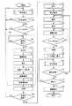
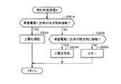
図9〜図13のフローチャートを参照して、ブラッシング評価のフローを具体的に説明する。図9はブラッシング評価のためのメインルーチンのフローチャートであり、図10〜図13はメインルーチンの各処理の詳細を示すフローチャートである。なお、以下に説明する処理は、特にことわりのない限り、CPU120がメモリ121に格納されているプログラムに従って実行する処理である。 The flow of brushing evaluation will be specifically described with reference to the flowcharts of FIGS. FIG. 9 is a flowchart of a main routine for brushing evaluation, and FIGS. 10 to 13 are flowcharts showing details of each process of the main routine. Note that the processing described below is processing executed by the
なお、ユーザは、ブラッシング部位にブラシ210を移し、当該部位の歯垢量を検出する場合には、LED400からの出射光がブラッシング部位に照射されるように、すなわちブラシ210が植毛された面の背面をブラッシング部位に対面するように、電動歯ブラシ1を持ち替えると想定する。 When the user moves the
まず、電動歯ブラシ1のスイッチSWのスイッチ402操作されると、操作受付部505から電源ONの操作信号が出力され、CPU120により、ブラッシングの部位が推定される(ステップT3)。 First, when the
ブラッシングの部位推定について図10〜図13のフローチャートを参照して説明する。 Brushing site estimation will be described with reference to the flowcharts of FIGS.
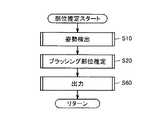
まず、姿勢検出部510は、加速度センサ15の出力に基づきブラシの姿勢(傾き)を検出する(ステップS(以下、単にSと略す)10)。次に、部位推定部520は、少なくともS10で検出された姿勢に基づいてブラッシング部位を推定し、推定した部位の情報を出力する(S20)。推定された部位は、一時的にメモリ121に格納される。また、表示制御部570は、推定された部位の情報をデータ送信部123を介して表示器110に出力する。表示器110では、部位の情報がディスプレイ111に表示される(S60)。これにより、ユーザは、現在のブラッシング部位を確認できる。また、推定された部位の情報はメモリ121に一時的に格納される。その後、図9の処理に戻る。 First, the
以下、S10〜S60の処理を詳しく説明する。
(姿勢の検出)
図11は姿勢検出処理(S10)のフローチャートである。Hereinafter, the processing of S10 to S60 will be described in detail.
(Attitude detection)
FIG. 11 is a flowchart of the posture detection process (S10).
姿勢検出部510は、加速度センサ15からx、y、zそれぞれの出力Ax、Ay、Azを取得する(S100)。Axはx方向の加速度成分、Ayはy方向の加速度成分、Azはz方向の加速度成分を表す。電動歯ブラシ1が静止状態にあるとき(加速度センサ15に動加速度が作用していないとき)は、Ax、Ay、Azの合成ベクトルAが重力加速度に相当する。ここでは、A=(Ax、Ay、Az)を姿勢ベクトルとよぶ。 The
ここで、姿勢ベクトルA=(Ax、Ay、Az)の大きさが1.2g(gは重力加速度)より大きい場合は(S101;YES)、エラーを返す(S102)。加速度センサ出力に動加速度成分が多く含まれていると、重力加速度の方向(つまりブラシの三次元姿勢)を正確に特定するのが難しくなるからである。なお、S102のようにエラーを返すのではなく、合成ベクトルの大きさが1.2g以下となる加速度センサ出力Ax、Ay、Azが得られるまでS100とS101の処理を繰返すようにしてもよい。なお、エラー判定のしきい値は1.2gに限らず、他の値でもよい。 If the orientation vector A = (Ax, Ay, Az) is larger than 1.2 g (g is gravitational acceleration) (S101; YES), an error is returned (S102). This is because if the acceleration sensor output contains many dynamic acceleration components, it is difficult to accurately specify the direction of gravitational acceleration (that is, the three-dimensional posture of the brush). Instead of returning an error as in S102, the processing of S100 and S101 may be repeated until acceleration sensor outputs Ax, Ay, Az with a combined vector size of 1.2 g or less are obtained. Note that the threshold for error determination is not limited to 1.2 g, but may be other values.
(ブラッシング部位の推定)
図12および図13は部位推定部520によるブラッシング部位の推定処理(S20)のフローチャートである。また図14および図15は、ブラッシング部位ごとの加速度センサ出力Ax、Ay、Azの一例を示す図である。(Brushing site estimation)
12 and 13 are flowcharts of the brushing site estimation process (S20) by the
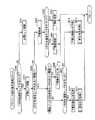
まずCPU120は、z方向の加速度センサの出力Azに基づき、上顎か下顎かを判定する(S700)。上顎の歯列をブラッシングするときはブラシ面が少なからず上向きになり、下顎の歯列をブラッシングするときはブラシ面が少なからず下向きになることに着目した判定である。Az>0の場合は下顎(S801)、Az≦0の場合は上顎(S701)と判定される。 First, the
(1)上顎の場合
CPU120は、y方向の加速度センサの出力Ayに基づいて前歯か否かを判定する(S702)。前歯をブラッシングするときは本体部2が比較的水平になるが、臼歯をブラッシングするときは唇との干渉があるため本体部2が斜めにならざるをえないことに着目した判定である。Ay≦閾値aの場合は上顎前歯と判定される(S703)。(1) In the case of the upper jaw The
上顎前歯と判定した場合、CPU120は、x方向の加速度センサの出力Axに基づいて頬側か舌側かを判定する(S704)。頬側と舌側とではブラシの向きが反転することに着目した判定である。Ax>0の場合は「上顎前頬側」と判定され(S705)、Ax≦0の場合は「上顎前舌側」と判定される(S706)。 If it is determined that the upper jaw is an anterior maxillary tooth, the
一方、S702で上顎前歯でないと判定した場合、CPU120は、x方向の加速度センサの出力Axに基づいて噛み合わせ面か否かを判定する(S707)。噛み合わせ面をブラッシングするときはブラシ面がほぼ水平になり、Axの出力が非常に小さくなること
に着目した判定である。閾値b>Ax>閾値cの場合は「上顎左噛み合わせ面または上顎右噛み合わせ面」と判定される(S708)。なお、本実施形態では、上顎左噛み合わせ面と上顎右噛み合わせ面とをとくに区別していない。噛み合わせ面の場合、左右でブラッシング動作を変える必要性が小さいからである。On the other hand, if it is determined in step S702 that the tooth is not an upper front tooth, the
Ax≧閾値bまたはAx≦閾値cの場合、CPU120は、Axが0より大きいか否かで、ブラシ面の向きを判定する(S709)。頬側と舌側とではブラシ面の向きが反転することに着目した判定である。Ax>0の場合は「上顎右頬側または上顎左舌側」と判定され(S710)、Ax≦0の場合は「上顎左頬側または上顎右舌側」と判定される(S712)。 When Ax ≧ threshold b or Ax ≦ threshold c, the
「上顎右頬側または上顎左舌側」と判定された場合、部位判定処理Aが実行される(S710、S711)。「上顎左頬側または上顎右舌側」と判定された場合、部位判定処理Bが実行される(S712、S713)。これらの部位判定処理A,Bについては後述する。 When it is determined that “upper right jaw side or upper left tongue side”, the region determination process A is executed (S710, S711). When it is determined that “the upper jaw left cheek side or the upper jaw right tongue side”, the region determination process B is executed (S712, S713). These part determination processes A and B will be described later.
(2)下顎の場合
CPU120は、y方向の加速度センサの出力Ayに基づいて前歯か否かを判定する(S802)。前歯をブラッシングするときは本体部2が比較的水平になるが、臼歯をブラッシングするときは唇との干渉があるため本体部2が斜めにならざるをえないことに着目した判定である。Ay≦閾値dの場合は下顎前歯と判定される(S803)。(2) In the case of the lower jaw The
下顎前歯と判定した場合、CPU120は、x方向の加速度センサの出力Axに基づいて頬側か舌側かを判定する(S804)。頬側と舌側とではブラシの向きが反転することに着目した判定である。Ax<0の場合は「下顎前頬側」と判定され(S805)、Ax≧0の場合は「下顎前舌側」と判定される(S806)。 If it is determined that it is a lower anterior tooth, the
一方、S802で下顎前歯でないと判定した場合、CPU120は、x方向の加速度センサの出力Axに基づいて噛み合わせ面か否かを判定する(S807)。噛み合わせ面をブラッシングするときはブラシ面がほぼ水平になり、Axの出力が非常に小さくなることに着目した判定である。閾値e>Ax>閾値fの場合は「下顎左噛み合わせ面または下顎右噛み合わせ面」と判定される(S808)。なお、本実施形態では、下顎左噛み合わせ面と下顎右噛み合わせ面とをとくに区別していない。噛み合わせ面の場合、左右でブラッシング動作を変える必要性が小さいからである。 On the other hand, if it is determined in S802 that the tooth is not a mandibular front tooth, the
Ax≧閾値eまたはAx≦閾値fの場合、CPU120は、Axが0より大きいか否かで、ブラシ面の向きを判定する(S809)。頬側と舌側とではブラシ面の向きが反転することに着目した判定である。Ax>0の場合は「下顎右頬側または下顎左舌側」と判定され(S810)、Ax≦0の場合は「下顎左頬側または下顎右舌側」と判定される(S811)。 When Ax ≧ threshold e or Ax ≦ threshold f, the
「下顎右頬側または下顎左舌側」と判定された場合、部位判定処理Cが実行される(S811)。「下顎左頬側または下顎右舌側」と判定された場合、部位判定処理Dが実行される(S812、S813)。 When it is determined that “the lower jaw right cheek side or the lower jaw left tongue side”, the part determination process C is executed (S811). When it is determined that “the lower jaw left cheek side or the lower jaw right tongue side”, the part determination process D is executed (S812, S813).
上記判定アルゴリズムはあくまでも一例を示したものにすぎず、加速度センサ15の出力Ax、Ay、Azからブラッシング部位を特定できるのであればどのような判定アルゴリズムでも構わない。たとえばAx、Ay、Azの値をそのまま判定の変数として用いるのでなく、Ax、Ay、Azを適宜組み合わせることで得られる2次変数を判定に用いてもよい。2次変数は、たとえば、Ay/Az、Ax・Ax+Ay・Ay、Az−Axなど
、任意に設定できる。あるいは、各軸の加速度情報Ax、Ay、Azを、角度情報(姿勢角)α、β、γに変換した後で、ブラッシング部位を判定してもよい。たとえば、重力加速度方向に対するx軸の角度をロール角α、重力加速度方向に対するy軸の角度をピッチ角β、重力加速度方向に対するz軸の角度をヨー角γのように定義すればよい。判定に用いる閾値は臨床実験等の結果から決定することができる。The above determination algorithm is merely an example, and any determination algorithm may be used as long as the brushing part can be specified from the outputs Ax, Ay, and Az of the
(部位判定処理)
右頬側または左舌側の歯列面、あるいは、左頬側または右舌側の歯列面と判定された場合に頬側か舌側かを判定する処理について説明する。つまり、「上顎右頬側または上顎左舌側」、「上顎左頬側または上顎右舌側」、「下顎右頬側または下顎左舌側」あるいは「下顎左頬側または下顎右舌側」と判定された場合に、頬側か舌側(口蓋側)かを判定するための部位判定処理について説明する。(Part determination process)
A process for determining whether the buccal side or the left tongue side or the left buccal side or the right lingual side of the dentition surface will be described. That is, “maxillary right cheek side or maxillary left lingual side”, “maxillary left cheek side or maxillary right lingual side”, “mandibular right cheek side or mandibular left lingual side” or “mandibular left cheek side or mandibular right lingual side” The part determination process for determining whether it is the cheek side or the tongue side (palate side) when it is determined will be described.
図16は、部位判定処理Aを示すフローチャートである。
部位推定部520は、ブラシ部3の背面に配置された電極(背面電極)521に生体がほぼ常時接触されているか否かを判断する(S201A)。たとえば、一定時間中、接触している時間の割合が80%以上であるか否かを判断する。生体への接触の有無は、検出部54が検出したインピーダンス値、あるいは、その変化に基づいて判定することができる。FIG. 16 is a flowchart showing the part determination process A.
The
図17は、背面電極521が生体に接触しているときと非接触のときの、生体を介した回路を概略的に示す図である。 FIG. 17 is a diagram schematically showing a circuit through the living body when the
図17の(A)に示されるように、背面電極521が生体と接触していないときは、空気部が存在するため、接触時と比べてインピーダンス値は大きい。これに対し、図17の(B)に示されるように、背面電極521が生体と接触しているときは、背面電極521を介して閉ループ回路が構成されるため、非接触時と比べてインピーダンス値は小さい。 As shown in FIG. 17A, when the
したがって、たとえば、インピーダンス値が予め定められた閾値以上か否かを検出することにより、接触/非接触を判定することができる。インピーダンスの閾値は、予め実験等を行なうことで決定される。 Therefore, for example, contact / non-contact can be determined by detecting whether the impedance value is equal to or greater than a predetermined threshold value. The impedance threshold is determined in advance through experiments or the like.
背面電極521に生体がほぼ常時接触していると判定された場合(S201AにてYES)、上顎右頬側と判定される(S202A)。頬側をブラッシングしているときは、電動歯ブラシ1のブラシ部3の背面がほぼ常時、頬内側と接触するからである。 When it is determined that the living body is in contact with the
一方、背面電極521に生体がほぼ常時接触していないと判定された場合(S201AにてNO)、さらに、背面電極521に生体が間欠的に接触しているか否かを判定する(S203A)。たとえば、一定時間中、接触している時間の割合が30%以上80%未満か否かを判断する。背面電極521に生体が間欠的に接触していると判定された場合(S203AにてYES)、上顎左舌側と判定される(S204A)。舌側(口蓋側)をブラッシングしているときは、電動歯ブラシ1のブラシ部3の背面が間欠的に、舌と接触するからである。 On the other hand, when it is determined that the living body is not substantially in contact with
背面電極521に生体が間欠的に接触していないと判定された場合(S203AにてNO)、エラーと判定される(S205A)。 If it is determined that the living body is not in intermittent contact with the back electrode 521 (NO in S203A), it is determined as an error (S205A).
本実施形態における頬側/舌側の判定方法の具体例を、図18に示す。なお、図18に示されるようなインピーダンスのレベルを得るためには、たとえば、体脂肪計などで採用されているように、ブラシ部3の背面に、電流印加用の電極の対と、電圧検出用の電極の対とが設けられればよい。 A specific example of the cheek / lingual determination method in the present embodiment is shown in FIG. In order to obtain the impedance level as shown in FIG. 18, for example, as employed in a body fat scale, a pair of electrodes for applying current and voltage detection are provided on the back of the
図18を参照して、時間t1〜t2の間は、インピーダンス値が常時閾値未満であるので、頬側面と判定される。これに対し、時間t2以降は、インピーダンス値が間欠的に、閾値以上であるので、舌側面と判定される。 Referring to FIG. 18, since the impedance value is always less than the threshold value between times t1 and t2, it is determined as the cheek side surface. On the other hand, after time t2, since the impedance value is intermittently greater than or equal to the threshold value, it is determined as the tongue side surface.
図19〜図21は、それぞれ、部位判定処理B,C,Dのフローチャートを示している。これらのフローチャートに示される処理は、基本的に図16に示した部位判定処理Aと同様である。図16の上顎右頬側(S202A),上顎左舌側(S204A)が、それぞれ、部位判定処理に移行する前の大まかな部位判定結果に応じて異なる点のみが、相違する。具体的には、図19の部位判定処理Bでは、図16の部位判定処理Aにおける上顎右頬側(S202A)および上顎左舌側(S204A)に代えて、それぞれ、上顎左頬側(S202B)および上顎右舌側(S204B)と判定される。図20の部位判定処理Cでは、図16の部位判定処理Aにおける上顎右頬側(S202A)および上顎左舌側(S204A)に代えて、それぞれ、下顎右頬側(S202C)および下顎左舌側(S204C)と判定される。図21の部位判定処理Dでは、図16の部位判定処理Aにおける上顎右頬側(S202A)および上顎左舌側(S204A)に代えて、それぞれ、下顎左頬側(S202D)および下顎右舌側(S204D)と判定される。 19 to 21 show flowcharts of the part determination processes B, C, and D, respectively. The processes shown in these flowcharts are basically the same as the part determination process A shown in FIG. The upper jaw right cheek side (S202A) and upper jaw left lingual side (S204A) in FIG. 16 are different only in the point that differs according to the rough site determination result before the shift to the site determination process. Specifically, in the part determination process B of FIG. 19, instead of the upper jaw right cheek side (S202A) and the upper left tongue side (S204A) in the part determination process A of FIG. 16, the upper jaw left cheek side (S202B), respectively. And it is determined as the maxillary right lingual side (S204B). In the part determination process C of FIG. 20, instead of the upper right cheek side (S202A) and the upper left lingual side (S204A) in the part determination process A of FIG. 16, the lower jaw right cheek side (S202C) and the lower jaw left tongue side, respectively. (S204C) is determined. In the part determination process D in FIG. 21, instead of the upper right cheek side (S202A) and the upper left lingual side (S204A) in the part determination process A in FIG. 16, the lower jaw left cheek side (S202D) and the lower jaw right tongue side, respectively. (S204D) is determined.
以上の処理によって、現在のブラッシング部位が、「上顎前頬側」(S705)、「上顎前舌側」(S706)、「上顎噛み合わせ面」(S708)、「上顎右頬側」(S202A)、「上顎左舌側」(S204A)、「上顎左頬側」(S202B)または「上顎右舌側」(S204B)、「下顎前頬側」(S805)、「下顎前舌側」(S806)、「下顎噛み合わせ面」(S808)、「下顎右頬側」(S202C)、「下顎左舌側」(S204C)、「下顎左頬側」(S202D)、「下顎右舌側」(S204D)のいずれかに特定される。 With the above processing, the current brushing sites are “maxillary front cheek side” (S705), “maxillary anterior tongue side” (S706), “maxillary meshing surface” (S708), and “maxillary right cheek side” (S202A). "Maxillary left lingual side" (S204A), "maxillary left cheek side" (S202B) or "maxillary right lingual side" (S204B), "mandibular anterior cheek side" (S805), "mandibular anterior tongue side" (S806) , “Mandibular meshing surface” (S808), “Mandibular right cheek side” (S202C), “Mandibular left tongue side” (S204C), “Mandibular left cheek side” (S202D), “Mandibular right tongue side” (S204D) It is specified in either.
なお、本実施形態において、頬側および舌側の判定は、一定時間インピーダンス値を検出することにより行なわれるため、頬側または舌側との判定結果は、ブラッシング部位推定処理(図10のS20)が複数サイクル行なわれてはじめて得られるものであってよい。 In the present embodiment, the determination on the cheek side and the tongue side is performed by detecting the impedance value for a certain period of time, so the determination result on the cheek side or the tongue side is the brushing part estimation process (S20 in FIG. 10). May be obtained only after a plurality of cycles.
また、本実施の形態では、噛み合わせ面の歯垢量は出力しないため、噛み合わせ面の部位判定は省略してもよい。 Further, in the present embodiment, since the amount of plaque on the meshing surface is not output, the part determination of the meshing surface may be omitted.
上述のように部位が推定されると、処理は、図9に戻る。図9を参照して、CPU120は直前に推定されてメモリ121に格納されていた情報が指す部位と、部位推定部520が現在出力する部位とを比較し、比較の結果に基づき、ブラッシング部位が変移したか否かを判定する(ステップT5)。判定結果に基づき、ブラッシング部位は別の部位に移ったと判定しない間は(ステップT5でNO)、ステップT3の処理が繰返されるが、ブラッシング部位は別の部位に移ったと判定すると(ステップT5でYES)、処理はステップT7に移行する。 When the site is estimated as described above, the processing returns to FIG. Referring to FIG. 9,
CPU120は、操作受付部505の出力する操作信号に基づき、ユーザがスイッチ403を操作したか否かを判定する(ステップT7)。操作したことが判定されない(ステップT7でNO)間は、処理はステップT3に戻り、以降の処理が同様に繰返される。 The
一方、ユーザがスイッチ403を操作したことが判定されると(ステップT7でYES)、歯垢量を検出するための処理(ルーチンRT)が実行される。 On the other hand, if it is determined that the user has operated switch 403 (YES in step T7), a process (routine RT) for detecting the amount of plaque is performed.
まず、姿勢検出部510は、加速度センサ15の出力に基づき、ブラシ210の植毛面の背面をブラッシング部位に対面するように電動歯ブラシ1が持替えされたか否かを判定する(ステップT9)。つまり、姿勢検出部510は、ステップT3で検出した直前の姿勢ベクトルA=(Ax、Ay、Az)の向きと、ステップT7のスイッチ403がON操作されたときに検出した姿勢ベクトルA=(Ax、Ay、Az)の向きの差異が、所定角度の範囲内であるか否かを判定することにより、持替えされたか否かを判定する。 First, the
差異が所定角度の範囲内であると判定すると、すなわち持ち替えはされていないと判定すると(ステップT9でNO)、持ち替え検出されるまでステップT9の処理が繰返されるが、差異が所定角度の範囲外であると判定すると、すなわちユーザが電動歯ブラシ1を持ち替えたと判定すると(ステップT9でYES)、処理はステップT11に移行する。 If it is determined that the difference is within the predetermined angle range, that is, it is determined that the change has not been made (NO in step T9), the process of step T9 is repeated until a change is detected, but the difference is outside the predetermined angle range. If it is determined that the user has changed the electric toothbrush 1 (YES in step T9), the process proceeds to step T11.
ステップT11では、電動歯ブラシ1の持替えによりブラシ210の植毛面の背面がブラッシング部位に対面する状態において、撮像部530は、LED400を制御して光を出射させる(ステップT11)。光出射し撮像を終了するまでの間、駆動制御部500は、振動部材5の運動を停止させるための制御信号を出力する。これにより、駆動信号供給部580からは、モータ10に対して回転を停止させるような駆動信号が供給される(ステップT13)。このように、モータ10の回転が停止しブラッシングが停止することで、ユーザに所定部位にブラシが配置されて撮像のタイミングであり、ブラシの移動が禁止される旨を報知できる。 In step T11, the
なお、撮像により取得される画像のブレを防止するために、すなわち撮像の期間において、歯垢量が検出されるべき部位に光を十分に照射でき、且つ十分な反射光量がCCD401に入射可能にするために、駆動信号は、必ずしも運動を停止させるようなものである必要はなく、運動を抑制するようなものであってもよい。たとえば、制御信号が指す周期またはDuty比を変更して、モータ10の回転に連動したブラシ210の周期的運動の周期を長くするようなものであってもよい。より具体的には、周期的運動が上下移動または左右移動の往復運動である場合には1往復に要する時間を長くし、回転運動である場合には1回転に要する時間を長くする。 In addition, in order to prevent blurring of an image acquired by imaging, that is, during the imaging period, it is possible to sufficiently irradiate the site where the plaque amount is to be detected, and a sufficient amount of reflected light can enter the
また、撮像により取得される画像のブレは、運動の周期を変更するのに代替して、画像処理により補正するようにしてもよい。 Further, blurring of an image acquired by imaging may be corrected by image processing instead of changing the cycle of movement.
このようにブラシ210の周期的運動が停止または抑制される期間において、LED400からの出射光のうち歯垢からの反射光を含む光はCCD401により受光されて、光電変換による画像信号が導出される。撮像部530は画像信号から画像データを取得する(ステップT15、T17)。 Thus, during the period when the periodic movement of the
画像データが取得されて撮像が終了すると、駆動制御部500は制御信号が指す周期またはDuty比を元に戻す。これにより、モータ10の回転に連動したブラシ210の周期的運動の周期が元に戻る(ステップT19)。運動周期が元に戻ったとき、ユーザは、ブラシ210をブラッシング部位に向けるように電動歯ブラシ1を持替えることで、次の部位に対するブラッシングを行うことができる。 When the image data is acquired and imaging is completed, the
上述の撮像により画像データが取得されると、歯垢検出部540は、撮像部530からの画像データに基づき、ステップT3で推定された部位における歯垢量を検出する(ステップT21)。歯垢量が検出されると、記憶部550は、検出された歯垢量を、ステップT3で推定された部位と、タイマ122の計時データとを対応付けて、テーブルTB1に格納する(ステップT23)。 When image data is acquired by the above imaging, the
その後、CPU121は、テーブルTB1のデータに基づき、図8に示した部位の全てについて歯垢量の検出が終了したか否かを判定する(ステップT25)。歯垢量が検出されていない部位があると判定すると(ステップT25でNO)、処理はステップT3に戻り、次の部位に対する処理が同様に行われるが、全部位について歯垢量が検出されていると判定されると(ステップT25でYES)、処理はステップT27に移行する。Thereafter, the
ステップT27では、今回の歯ブラシ時においてステップT3〜T25の処理によりテーブルTB1に格納された情報が読出部560により読出されて、表示制御部570によりデータ送信部123を介して表示器110のディスプレイ111に表示される(ステップT27)。 In step T27, the information stored in the table TB1 by the processing of steps T3 to T25 at the time of the current toothbrush is read by the
ステップT27における、表示の一例が図22に示される。表示制御部570は、読出部560によってメモリ121のテーブルTB1から各部位の歯垢量を読出し、たとえば、歯垢量を「0〜5%」、「5〜10%」、「10%〜」にランク付けし、「0〜5%」のみを“OK”と評価する。そのランク付けおよび評価結果は表示器110に送信される。表示器110のディスプレイ111には歯列が描画されており、その歯列中の歯垢量のランクに応じた色(「OK」は白色、「5〜10%」は黄色、「10%〜」は赤色など)で点灯する。このような表示をみることで、ユーザは歯列中のどの部位に歯垢が残っており、ブラッシングが不足しているかを直感的に把握できる。An example of the display in step T27 is shown in FIG. The
なお、ランク付けおよび評価結果は、ブラッシング時に部位が推定されるごとに、表示制御部570により、データ送信部123を介して表示器110のディスプレイ111に表示されるとしてもよい。 Note that the ranking and evaluation results may be displayed on the
図22の表示から、ユーザは歯垢が残る部位を確認して、当該部位のブラッシングを行うと、姿勢検出部510および部位推定部520により、ステップT3と同様にブラッシング部位が推定される(ステップT29)。部位が推定されると、表示制御部570は、ディスプレイ111の図22の当該部位を点滅表示することにより、ブラッシングを継続する旨を報知する(ステップT31)。これにより、ユーザに対し、点滅している期間(たとえば、10秒間)は当該部位に対する歯垢除去のためのブラッシング継続が促される。 When the user confirms the part where plaque remains from the display in FIG. 22 and brushes the part, the brushing part is estimated by the
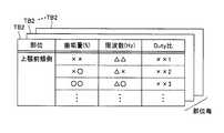
また、ステップT29で推定された部位の歯垢を確実に除去するための駆動信号がモータ10に供給される(ステップT35)。具体的には、読出部560は、ステップT29で推定された部位に基づきテーブルTB1を検索し、検索結果に基づき、テーブルTB1から当該部位に対応する歯垢量のうち最も最近に格納された歯垢量を読出す。そして、読出した歯垢量に基づきテーブルTB2から当該歯垢量に対応のデータを読出す。駆動制御部500は、読出されたデータ基づく制御信号を出力する(ステップT33)。 Further, a drive signal for reliably removing the plaque at the site estimated in step T29 is supplied to the motor 10 (step T35). Specifically, the
図23に示すように、部位ごとにテーブルTB2がメモリ121に予め格納される。テーブルTB2のデータは、実験により準備される。テーブルTB2には、対応する部位について歯垢量ごとに、当該歯垢量を除去するための駆動信号の周期を決定する周波数(単位:Hz)とDuty比とが格納されている。 As shown in FIG. 23, a table TB2 is stored in advance in the
これにより、ステップT31で報知がされる所定期間において、ユーザが所望した部位の歯垢を除去するための適切な周期とDuty比に基づく駆動信号によってブラッシングを行うことができる。すなわち、所望した部位の歯垢を除去するため、ブラシ210の周期的な運動であるブラッシングの周期は適切に変更されることになる。Thereby, in the predetermined period notified by step T31, it can brush by the drive signal based on the suitable period andDuty ratio for removing the plaque of the site | part which the user wanted. That is, in order to remove plaque at a desired site, the brushing cycle, which is a periodic motion of the
CPU120は、操作受付部505の出力に基づき、スイッチ403が操作されたか否かを判定する(ステップT37)。操作されないと判定されると(ステップT37でNO)、処理はステップT35に戻り、ブラッシングが継続する。一方、ユーザは上述の点滅表示が終了するなどして所望部位の歯垢は除去されたであろうから歯垢量を確認したいと希望するとスイッチ403を操作する(ステップT37でYES)。 The
スイッチ403が操作されると、前述したステップT9〜T21を含むルーチンRTが実行される。これにより、ステップT29で推定された部位に対するブラッシング後の歯垢量が検出されて、検出された歯垢量を用いてテーブルTB1の当該部位に対応する情報が更新されるとともに、検出された当該部位の歯垢量(更新後の歯垢量)はディスプレイ111に表示される(ステップT39)。ユーザは、表示から、磨き残しの歯垢が除去できたか否かを判別することができる。 When the
表示後は、部位推定処理が行われる(ステップT41)。推定の結果に基づき、ユーザがブラッシング部位を別の部位に移動させたか否かが判定される(ステップT43)。別の部位に移動したと判定されると(ステップT43でYES)、処理はステップT31に戻り、以降の処理が同様に繰返される。一方、部位は変移していないと判定されると(ステップT43でNO)、CPU120は操作受付部505の出力に基づきスイッチ402が操作されて電源OFF操作がされてブラッシングの運動の停止が要求されたか否かを判定する(ステップT45)。 After the display, a part estimation process is performed (step T41). Based on the estimation result, it is determined whether or not the user has moved the brushing part to another part (step T43). If it determines with having moved to another site | part (it is YES at step T43), a process will return to step T31 and subsequent processes will be repeated similarly. On the other hand, if it is determined that the part has not changed (NO in step T43), the
ブラッシング運動の停止要求がされていないと判定されると(ステップT45でNO)、処理はステップT41に戻りに、以降の処理が同様に繰返されるが、停止要求がされたと判定されると(ステップT45でYES)、駆動制御部500はブラッシングを停止するための制御信号を出力する。これにより、駆動信号供給部580によりモータ10への駆動信号の供給は停止し、モータ10は停止する。以上で図9の処理は終了する。 If it is determined that the brushing motion stop request is not made (NO in step T45), the process returns to step T41, and the subsequent processing is repeated in the same manner, but if it is determined that the stop request is made (step step). The
なお、図6では歯垢検出部540およびテーブルTB1は電動歯ブラシ1が備えたが、電動歯ブラシ1に代替して表示器110のMPU113が備えるようにしてもよく、または両方で備えるとしてもよい。 In FIG. 6, the dental
<他の実施の形態>
本実施の形態によれば、歯垢検出を指示するためのスイッチ403が操作されると(ステップT7でYES)、歯垢量が検出開始されるとしているが、スイッチ403の操作に代替してブラッシング部位の変移を検出すると、歯垢量が検出開始されるとしてもよい。また、本実施の形態でLED400とCCD401は図2の態様で装着される場合には、ステップT9の持替えの判定が必要とされるが、図2に代替して図5の態様で装着される場合には持替えの判定を省略することができる。<Other embodiments>
According to the present embodiment, when the
いずれにしても、LED400は撮像期間のみ光を出射し、撮像終了後からブラッシング部位が移動したことが検出されるまでの期間はLED400の光出射を含む撮像は停止されるから、電力の消費量を抑制することができる。 In any case, the
図9では、部位が推定された後に歯垢量が検出されるとしているが、歯垢検出は部位推定とは独立して行なわれても良い。つまり、ユーザがスイッチSWを操作して操作受付部505が撮像の指示を入力すると、撮像部530は、当該撮像指示に従って撮像するとしてもよい。これにより、当該操作がされたときにブラシ210が当てられている部位の撮像と歯垢量の検出とディスプレイ111による検出結果の表示(および/または撮像画像の表示)とが行なわれるとしてもよい。 In FIG. 9, the amount of plaque is detected after the site is estimated, but plaque detection may be performed independently of the site estimation. That is, when the user operates the switch SW and the
また、図9では、全部位の歯垢量をテーブルTB1に記録する処理(ステップT3〜T25)と、次に当該記録結果に基づく歯垢除去のブラッシングのための処理(ステップT27〜T47)とを連続して行うとしたが、処理の順番はこれに限定されない。 Further, in FIG. 9, processing for recording the plaque amount of all parts in the table TB1 (steps T3 to T25), and then processing for brushing removal of plaque based on the recording result (steps T27 to T47), However, the order of processing is not limited to this.
つまり、テーブルTB1に情報が予め格納されている場合には、電源ONの操作がされると当該情報に基づく歯垢除去のブラッシングのための処理(ステップT27〜T47)が行なわれるとしてもよい。この場合には、CPU120は、テーブルTB1の情報に基づき、全部位のうち歯垢量が「OK」と評価されない量であり、且つ所定期間(たとえば直近の3日間)、その歯垢量に変化がない部位を検出し、表示器110のディスプレイ111にその旨を図22のようにガイド表示する。これにより、ユーザは当該部位のブラッシングをスルーする癖があると判断することができる。たとえば、通常は手磨きブラシを使用し、たまに電動歯ブラシ1を利用するような場合は、CPU120は、部位ごとの前回検出の歯垢量と、今回検出の歯垢量とを比較し、比較結果に基づき歯垢量が変化していない部位は、手磨きによっては歯垢が除去されていない部位であると判別できる。したがって、その部位の磨きが常に不足している(ユーザはブラッシングをスルーする癖がある)とのガイダンスを表示器110を介して表示することができる。 That is, when information is stored in advance in the table TB1, processing for removing plaque (steps T27 to T47) based on the information may be performed when the power is turned on. In this case, based on the information in the table TB1, the
また、電動歯ブラシ1のブラッシング部位が、当該スルーする部位であると判定したときは、重点的なブラッシングポイントであることを表示器110により報知(「10秒間この歯を磨き続けて下さい」)するとしてもよい。 Further, when it is determined that the brushing part of the
また、ユーザ毎のテーブルTB1は、メモリ121から読出されてデータ送信部123によって、図示のない外部コンピュータ(サーバ装置)に送信し、外部コンピュータのメモリで管理するようにしてもよい。外部コンピュータのメモリは歯科医もアクセスできるとすれば、歯科医は、ユーザ毎のテーブルTB1の情報に基づき、容易に、ユーザ毎に定期的な歯科指導、適切な治療計画を立てることできる。 Further, the table TB1 for each user may be read from the
今回開示された実施の形態はすべての点で例示であって制限的なものではないと考えられるべきである。本発明の範囲は上記した説明ではなくて特許請求の範囲によって示され、特許請求の範囲と均等の意味および範囲内でのすべての変更が含まれることが意図される。 The embodiment disclosed this time should be considered as illustrative in all points and not restrictive. The scope of the present invention is defined by the terms of the claims, rather than the description above, and is intended to include any modifications within the scope and meaning equivalent to the terms of the claims.
1 電動歯ブラシ、2 本体部、3 ブラシ部、4 柄部、5 振動部材、10 モータ、11 回転軸、12 駆動回路、13 充電池、14 コイル、15 加速度センサ、20 ステム部、21 ブラシ部品、30 偏心軸、50 接触検知部、52 電極部、54 検出部、61,62,63,521,522 電極、64,65 リード線、100 充電器、110 表示器、111 ディスプレイ、112 データ受信部、121 メモリ、122 タイマ、123 データ送信部、202 弾性部材、203 軸受、210 ブラシ、402,403,SW スイッチ、500 駆動制御部、505 操作受付部、510 姿勢検出部、520 部位推定部、521 背面電極、522 本体電極、530 撮像部、540 歯垢検出部、550 記憶部、560 読出部、570 表示制御部、580 駆動信号供給部、600 端部。 DESCRIPTION OF
Claims (11)
Translated fromJapanese前記ケア部材の姿勢を検出するための姿勢検出部と、
検出された姿勢に基づいて口腔のケア部位を推定するための部位推定部と、
歯垢が反応する所定波長の光を出射する光源と、
光を受光し電気信号に変換する光電変換部と、
前記光源によりケア部位に対し光を出射させ、ケア部位からの反射光の前記光電変換部によって変換された電気信号に基づき画像データを取得する撮像部と、
前記撮像部が取得した画像データに基づき、ケア部位の歯垢量を検出するための歯垢検出部と、
前記部位推定部により推定されるケア部位と、当該ケア部位について前記歯垢検出部により検出される歯垢量とを対応付けてメモリに記憶するための記憶部と、を備える、口腔ケア装置。A care member for caring for the oral cavity;
A posture detection unit for detecting the posture of the care member;
A site estimation unit for estimating a care site of the oral cavity based on the detected posture;
A light source that emits light of a predetermined wavelength to which plaque reacts;
A photoelectric conversion unit that receives light and converts it into an electrical signal;
An imaging unit that emits light to a care site by the light source, and acquires image data based on an electrical signal converted by the photoelectric conversion unit of reflected light from the care site;
Based on the image data acquired by the imaging unit, a plaque detection unit for detecting the amount of plaque in the care site;
An oral care apparatus comprising: a storage unit for storing a care site estimated by the site estimation unit and a plaque amount detected by the plaque detection unit for the care site in association with each other.
前記駆動部を制御する駆動制御部と、をさらに備え、
前記駆動制御部は、
前記撮像部が前記光源により光を出射させるときは、前記ケア部材の運動の周期が長くなるように、前記駆動部を制御する、請求項1に記載の口腔ケア装置。A drive for periodically moving the care member;
A drive control unit for controlling the drive unit,
The drive control unit
The oral care device according to claim 1, wherein when the imaging unit causes the light source to emit light, the driving unit is controlled so that a period of movement of the care member becomes longer.
前記駆動部を制御する駆動制御部と、をさらに備え、
前記駆動制御部は、
前記撮像部が前記光源により光を出射させるときは、前記ケア部材の運動が停止するように、前記駆動部を制御する、請求項1に記載の口腔ケア装置。A drive for periodically moving the care member;
A drive control unit for controlling the drive unit,
The drive control unit
The oral care device according to claim 1, wherein when the imaging unit causes the light source to emit light, the driving unit is controlled so that the movement of the care member stops.
前記部位推定部により推定されるケア部位に対応して前記メモリに記憶されている歯垢量に基づき、前記周期が変更されるように前記駆動部を制御する、請求項2または3に記載の口腔ケア装置。The drive control unit
The said drive part is controlled so that the said period may be changed based on the amount of plaque memorize | stored in the said memory corresponding to the care site | part estimated by the said site | part estimation part. Oral care device.
前記撮像部は、前記操作受付部が操作を受付けたとき、前記光源により光を出射させる、請求項1に記載の口腔ケア装置。An operation receiving unit that receives an operation for instructing imaging;
The oral imaging device according to claim 1, wherein the imaging unit causes the light source to emit light when the operation receiving unit receives an operation.
光源の光出射面と光電変換部の受光面は、前記取り付け面の背面に設けられる、請求項1から7のいずれか1項に記載の口腔ケア装置。A mounting surface for mounting the care member;
The oral care device according to any one of claims 1 to 7, wherein a light emitting surface of the light source and a light receiving surface of the photoelectric conversion unit are provided on a back surface of the mounting surface.
Priority Applications (5)
| Application Number | Priority Date | Filing Date | Title |
|---|---|---|---|
| JP2011182263AJP5796408B2 (en) | 2011-08-24 | 2011-08-24 | Oral care device |
| DE112012003494.5TDE112012003494B4 (en) | 2011-08-24 | 2012-06-07 | Oral care device in application for removing dental plaque |
| CN201280041064.5ACN103764063B (en) | 2011-08-24 | 2012-06-07 | For removing the oral care appliance of dental tartar |
| US14/237,817US8839476B2 (en) | 2011-08-24 | 2012-06-07 | Oral care apparatus applied to the removal of dental plaque |
| PCT/JP2012/064626WO2013027462A1 (en) | 2011-08-24 | 2012-06-07 | Oral care device applied to remove tooth plaque |
Applications Claiming Priority (1)
| Application Number | Priority Date | Filing Date | Title |
|---|---|---|---|
| JP2011182263AJP5796408B2 (en) | 2011-08-24 | 2011-08-24 | Oral care device |
Publications (3)
| Publication Number | Publication Date |
|---|---|
| JP2013042906A JP2013042906A (en) | 2013-03-04 |
| JP2013042906A5 JP2013042906A5 (en) | 2014-10-09 |
| JP5796408B2true JP5796408B2 (en) | 2015-10-21 |
Family
ID=47746217
Family Applications (1)
| Application Number | Title | Priority Date | Filing Date |
|---|---|---|---|
| JP2011182263AActiveJP5796408B2 (en) | 2011-08-24 | 2011-08-24 | Oral care device |
Country Status (5)
| Country | Link |
|---|---|
| US (1) | US8839476B2 (en) |
| JP (1) | JP5796408B2 (en) |
| CN (1) | CN103764063B (en) |
| DE (1) | DE112012003494B4 (en) |
| WO (1) | WO2013027462A1 (en) |
Families Citing this family (114)
| Publication number | Priority date | Publication date | Assignee | Title |
|---|---|---|---|---|
| US9403238B2 (en) | 2011-09-21 | 2016-08-02 | Align Technology, Inc. | Laser cutting |
| US9375300B2 (en) | 2012-02-02 | 2016-06-28 | Align Technology, Inc. | Identifying forces on a tooth |
| US9220580B2 (en) | 2012-03-01 | 2015-12-29 | Align Technology, Inc. | Determining a dental treatment difficulty |
| US9414897B2 (en) | 2012-05-22 | 2016-08-16 | Align Technology, Inc. | Adjustment of tooth position in a virtual dental model |
| US9517015B2 (en) | 2012-12-21 | 2016-12-13 | Koninklijke Philips N.V. | Dental apparatus and method of utilizing the same |
| RU2662072C2 (en) | 2013-03-11 | 2018-07-23 | Конинклейке Филипс Н.В. | Electric toothbrush |
| US9220583B2 (en)* | 2013-10-22 | 2015-12-29 | Plaqless Ltd | Dental care device for detection and removal of plaque |
| AU2013101537B4 (en)* | 2013-11-23 | 2014-09-04 | Candra Innovations Pty Ltd | Intraoral camera for oral hygiene devices |
| WO2015113872A1 (en)* | 2014-01-30 | 2015-08-06 | Koninklijke Philips N.V. | Reducing blockages of a plaque detection stream probe |
| US20150257636A1 (en)* | 2014-03-11 | 2015-09-17 | Craig S. Kohler | Dental Instrument Camera Apparatus and Methods of Using the Same |
| KR101559661B1 (en)* | 2014-03-31 | 2015-10-15 | 주식회사 로보프린트 | Toothbrush with a camera and tooth medical examination system using this |
| US10772506B2 (en) | 2014-07-07 | 2020-09-15 | Align Technology, Inc. | Apparatus for dental confocal imaging |
| EP2976965A1 (en) | 2014-07-22 | 2016-01-27 | Braun GmbH | Fastenable device for oral cavity position detection |
| EP2976966A1 (en)* | 2014-07-22 | 2016-01-27 | Braun GmbH | Fastenable device for oral cavity position detection |
| US9675430B2 (en) | 2014-08-15 | 2017-06-13 | Align Technology, Inc. | Confocal imaging apparatus with curved focal surface |
| US9610141B2 (en) | 2014-09-19 | 2017-04-04 | Align Technology, Inc. | Arch expanding appliance |
| US10449016B2 (en) | 2014-09-19 | 2019-10-22 | Align Technology, Inc. | Arch adjustment appliance |
| CN105616028B (en)* | 2014-10-28 | 2018-09-18 | 小米科技有限责任公司 | tooth detection method and device |
| US9744001B2 (en) | 2014-11-13 | 2017-08-29 | Align Technology, Inc. | Dental appliance with cavity for an unerupted or erupting tooth |
| US10504386B2 (en) | 2015-01-27 | 2019-12-10 | Align Technology, Inc. | Training method and system for oral-cavity-imaging-and-modeling equipment |
| JP6298938B2 (en)* | 2015-02-19 | 2018-03-20 | 昭則 小山 | Toothbrush system with plaque detection function |
| EP3282540B1 (en)* | 2015-04-06 | 2021-04-28 | Panasonic Intellectual Property Management Co., Ltd. | Electric apparatus unit |
| KR101665123B1 (en)* | 2015-04-14 | 2016-10-12 | (주)삼보에이팩 | A tooth management brush and a tooth management system |
| JP6599652B2 (en)* | 2015-06-12 | 2019-10-30 | オムロンヘルスケア株式会社 | electric toothbrush |
| EP4245184A3 (en)* | 2015-06-12 | 2023-10-25 | Colgate-Palmolive Company | Electric toothbrush and brush unit |
| DE102015009215A1 (en)* | 2015-07-15 | 2017-01-19 | Arnulf Deinzer | Apparatus and method for monitoring and teaching elementary cleaning and hygiene movements in oral hygiene |
| US10248883B2 (en) | 2015-08-20 | 2019-04-02 | Align Technology, Inc. | Photograph-based assessment of dental treatments and procedures |
| JP2017056198A (en)* | 2015-09-14 | 2017-03-23 | シチズン時計株式会社 | toothbrush |
| RU2673110C1 (en)* | 2015-10-21 | 2018-11-22 | Конинклейке Филипс Н.В. | Methods and systems for determining location of mouth cleaning device |
| US11554000B2 (en) | 2015-11-12 | 2023-01-17 | Align Technology, Inc. | Dental attachment formation structure |
| US11931222B2 (en) | 2015-11-12 | 2024-03-19 | Align Technology, Inc. | Dental attachment formation structures |
| CN106806032A (en)* | 2015-11-30 | 2017-06-09 | 英业达科技有限公司 | Electric toothbrush system |
| US10405754B2 (en)* | 2015-12-01 | 2019-09-10 | University Of South Florida | Standardized oral health assessment and scoring using digital imaging |
| US11596502B2 (en) | 2015-12-09 | 2023-03-07 | Align Technology, Inc. | Dental attachment placement structure |
| US11103330B2 (en) | 2015-12-09 | 2021-08-31 | Align Technology, Inc. | Dental attachment placement structure |
| JP6832191B2 (en)* | 2016-03-17 | 2021-02-24 | シチズン時計株式会社 | toothbrush |
| JP6858588B2 (en)* | 2016-03-24 | 2021-04-14 | オムロンヘルスケア株式会社 | Plaque detector and toothbrush |
| CN105877691A (en)* | 2016-04-05 | 2016-08-24 | 苏州佳像视讯科技有限公司 | Multifunctional oral peeping camera device |
| JP6711106B2 (en) | 2016-04-22 | 2020-06-17 | オムロンヘルスケア株式会社 | toothbrush |
| JP6786866B2 (en)* | 2016-05-11 | 2020-11-18 | オムロンヘルスケア株式会社 | toothbrush |
| US20170333135A1 (en)* | 2016-05-18 | 2017-11-23 | Fei Gao | Operational system on a workpiece and method thereof |
| US10383705B2 (en) | 2016-06-17 | 2019-08-20 | Align Technology, Inc. | Orthodontic appliance performance monitor |
| WO2017218947A1 (en) | 2016-06-17 | 2017-12-21 | Align Technology, Inc. | Intraoral appliances with sensing |
| CN106175957B (en)* | 2016-06-30 | 2018-01-02 | 上海携福电器有限公司 | Fixed structure for electric cleaning apparatus drive device |
| US10507087B2 (en) | 2016-07-27 | 2019-12-17 | Align Technology, Inc. | Methods and apparatuses for forming a three-dimensional volumetric model of a subject's teeth |
| CA3030676A1 (en) | 2016-07-27 | 2018-02-01 | Align Technology, Inc. | Intraoral scanner with dental diagnostics capabilities |
| JP6805645B2 (en) | 2016-08-30 | 2020-12-23 | オムロンヘルスケア株式会社 | Toothbrush and system |
| KR101707173B1 (en)* | 2016-10-05 | 2017-02-15 | (주)삼보에이팩 | A tooth management brush and a tooth management system |
| CN117257492A (en) | 2016-11-04 | 2023-12-22 | 阿莱恩技术有限公司 | Method and apparatus for dental imaging |
| JP7394622B2 (en)* | 2016-11-09 | 2023-12-08 | コーニンクレッカ フィリップス エヌ ヴェ | Network for collaborative personal care devices |
| US11213120B2 (en) | 2016-11-14 | 2022-01-04 | Colgate-Palmolive Company | Oral care system and method |
| US10582764B2 (en) | 2016-11-14 | 2020-03-10 | Colgate-Palmolive Company | Oral care system and method |
| US10835028B2 (en)* | 2016-11-14 | 2020-11-17 | Colgate-Palmolive Company | Oral care system and method |
| US11043141B2 (en) | 2016-11-14 | 2021-06-22 | Colgate-Palmolive Company | Oral care system and method |
| US11361672B2 (en) | 2016-11-14 | 2022-06-14 | Colgate-Palmolive Company | Oral care system and method |
| RU2759877C2 (en)* | 2016-12-01 | 2021-11-18 | Конинклейке Филипс Н.В. | Method for determining the orientation of the head of the user during teeth brushing |
| EP3549061A4 (en)* | 2016-12-01 | 2020-07-08 | University Of South Florida | STANDARDIZED ORAL HEALTH ASSESSMENT USING DIGITAL IMAGE |
| AU2017366755B2 (en) | 2016-12-02 | 2022-07-28 | Align Technology, Inc. | Methods and apparatuses for customizing rapid palatal expanders using digital models |
| US11026831B2 (en) | 2016-12-02 | 2021-06-08 | Align Technology, Inc. | Dental appliance features for speech enhancement |
| WO2018102770A1 (en) | 2016-12-02 | 2018-06-07 | Align Technology, Inc. | Force control, stop mechanism, regulating structure of removable arch adjustment appliance |
| EP3547952B1 (en) | 2016-12-02 | 2020-11-04 | Align Technology, Inc. | Palatal expander |
| CN106510608A (en)* | 2016-12-12 | 2017-03-22 | 张雨同 | Visualized oral cavity detection apparatus and visualized diastema cleaning apparatus |
| WO2018112309A1 (en)* | 2016-12-15 | 2018-06-21 | Water Pik, Inc. | Brushing device with illumination features |
| US10548700B2 (en) | 2016-12-16 | 2020-02-04 | Align Technology, Inc. | Dental appliance etch template |
| US10456043B2 (en) | 2017-01-12 | 2019-10-29 | Align Technology, Inc. | Compact confocal dental scanning apparatus |
| US10779718B2 (en) | 2017-02-13 | 2020-09-22 | Align Technology, Inc. | Cheek retractor and mobile device holder |
| WO2018183358A1 (en) | 2017-03-27 | 2018-10-04 | Align Technology, Inc. | Apparatuses and methods assisting in dental therapies |
| US10613515B2 (en) | 2017-03-31 | 2020-04-07 | Align Technology, Inc. | Orthodontic appliances including at least partially un-erupted teeth and method of forming them |
| US11045283B2 (en) | 2017-06-09 | 2021-06-29 | Align Technology, Inc. | Palatal expander with skeletal anchorage devices |
| CN116942335A (en) | 2017-06-16 | 2023-10-27 | 阿莱恩技术有限公司 | Automatic detection of tooth type and eruption status |
| US10639134B2 (en) | 2017-06-26 | 2020-05-05 | Align Technology, Inc. | Biosensor performance indicator for intraoral appliances |
| US10376149B2 (en) | 2017-07-11 | 2019-08-13 | Colgate-Palmolive Company | Oral care evaluation system and process |
| US10885521B2 (en) | 2017-07-17 | 2021-01-05 | Align Technology, Inc. | Method and apparatuses for interactive ordering of dental aligners |
| CN111107806B (en) | 2017-07-21 | 2022-04-19 | 阿莱恩技术有限公司 | Jaw profile anchoring |
| CN110996842B (en) | 2017-07-27 | 2022-10-14 | 阿莱恩技术有限公司 | Tooth Staining, Transparency and Glazing |
| EP4278957A3 (en) | 2017-07-27 | 2024-01-24 | Align Technology, Inc. | System and methods for processing an orthodontic aligner by means of an optical coherence tomography |
| US12274597B2 (en)* | 2017-08-11 | 2025-04-15 | Align Technology, Inc. | Dental attachment template tray systems |
| US11116605B2 (en) | 2017-08-15 | 2021-09-14 | Align Technology, Inc. | Buccal corridor assessment and computation |
| US11123156B2 (en) | 2017-08-17 | 2021-09-21 | Align Technology, Inc. | Dental appliance compliance monitoring |
| US10098448B1 (en)* | 2017-08-29 | 2018-10-16 | Timothy Beach | Toothbrush timer |
| US12171575B2 (en) | 2017-10-04 | 2024-12-24 | Align Technology, Inc. | Intraoral systems and methods for sampling soft-tissue |
| US10813720B2 (en) | 2017-10-05 | 2020-10-27 | Align Technology, Inc. | Interproximal reduction templates |
| CN109662792A (en)* | 2017-10-13 | 2019-04-23 | 周星 | Visual cleaning of teeth sanding and polishing instrument |
| CN111565668B (en) | 2017-10-27 | 2022-06-07 | 阿莱恩技术有限公司 | Substitute occlusion adjusting structure |
| CN111295153B (en) | 2017-10-31 | 2023-06-16 | 阿莱恩技术有限公司 | Dental appliance with selective bite loading and controlled tip staggering |
| CN119235481A (en) | 2017-11-01 | 2025-01-03 | 阿莱恩技术有限公司 | Automatic treatment planning |
| US11534974B2 (en) | 2017-11-17 | 2022-12-27 | Align Technology, Inc. | Customized fabrication of orthodontic retainers based on patient anatomy |
| US11219506B2 (en) | 2017-11-30 | 2022-01-11 | Align Technology, Inc. | Sensors for monitoring oral appliances |
| US11432908B2 (en) | 2017-12-15 | 2022-09-06 | Align Technology, Inc. | Closed loop adaptive orthodontic treatment methods and apparatuses |
| US10980613B2 (en) | 2017-12-29 | 2021-04-20 | Align Technology, Inc. | Augmented reality enhancements for dental practitioners |
| US10813727B2 (en) | 2018-01-26 | 2020-10-27 | Align Technology, Inc. | Diagnostic intraoral tracking |
| US11937991B2 (en) | 2018-03-27 | 2024-03-26 | Align Technology, Inc. | Dental attachment placement structure |
| EP3773320B1 (en) | 2018-04-11 | 2024-05-15 | Align Technology, Inc. | Releasable palatal expanders |
| WO2020012489A1 (en)* | 2018-07-13 | 2020-01-16 | Plaqless Ltd | Intraoral imaging device |
| GB2575781B (en) | 2018-07-16 | 2022-02-23 | Dyson Technology Ltd | A cleaning appliance |
| CN109199621A (en)* | 2018-10-19 | 2019-01-15 | 张晨晨 | A kind of automedica oral care device and its working method |
| KR102025345B1 (en)* | 2018-12-28 | 2019-09-25 | 비비씨 주식회사 | Toothbrush for oral diagnosis |
| DE202019105110U1 (en)* | 2019-09-16 | 2020-12-18 | Bioinitials Gmbh | Brush head, toothbrush, exchange station and device for health monitoring |
| JP2021083482A (en)* | 2019-11-25 | 2021-06-03 | 株式会社村田製作所 | Device for measuring inside of oral cavity and system for measuring inside of oral cavity |
| US11484253B2 (en) | 2019-12-19 | 2022-11-01 | Colgate-Palmolive Company | Oral care system |
| US11470954B2 (en) | 2019-12-19 | 2022-10-18 | Colgate-Palmolive Company | Oral care system |
| USD950956S1 (en) | 2019-12-19 | 2022-05-10 | Colgate-Palmolive Company | Oral care implement handle |
| US11406480B2 (en) | 2019-12-19 | 2022-08-09 | Colgate-Palmolive Company | Oral care implement and refill head thereof |
| USD967632S1 (en) | 2019-12-19 | 2022-10-25 | Colgate-Palmolive Company | Replacement head for a toothbrush |
| US11425995B2 (en) | 2019-12-19 | 2022-08-30 | Colgate-Palmolive Company | Powered oral care implement |
| USD950955S1 (en) | 2019-12-19 | 2022-05-10 | Colgate-Palmolive Company | Oral care implement |
| CN211485031U (en)* | 2019-12-27 | 2020-09-15 | 南昌思麦科技有限公司 | Luminous electric toothbrush of wireless induction power supply |
| GB2591145B (en) | 2020-01-20 | 2022-04-20 | Dyson Technology Ltd | A dental treatment appliance |
| CN212940042U (en)* | 2020-06-10 | 2021-04-13 | 成都仁恒美光科技有限公司 | A hollow rotary visual electric toothbrush |
| CN115835798A (en) | 2020-06-22 | 2023-03-21 | 高露洁-棕榄公司 | Oral care systems and methods for promoting oral hygiene |
| CN118695801A (en)* | 2022-02-17 | 2024-09-24 | 松下知识产权经营株式会社 | Intraoral camera system and signal processing method |
| CN116578253B (en)* | 2022-05-31 | 2023-12-19 | 广州星际悦动股份有限公司 | Display control method, device, storage medium and oral care system |
| WO2024221824A1 (en)* | 2023-04-27 | 2024-10-31 | 广州星际悦动股份有限公司 | Information display method and apparatus, storage medium and electronic device |
| JP2025048954A (en)* | 2023-09-21 | 2025-04-03 | ソフトバンクグループ株式会社 | system |
Family Cites Families (47)
| Publication number | Priority date | Publication date | Assignee | Title |
|---|---|---|---|---|
| DE19605845A1 (en)* | 1996-02-16 | 1997-08-21 | Lingner & Fischer Gmbh | Device and method for the detection of dental plaque |
| US6200134B1 (en)* | 1998-01-20 | 2001-03-13 | Kerr Corporation | Apparatus and method for curing materials with radiation |
| GB9810471D0 (en) | 1998-05-16 | 1998-07-15 | Helmet Hund Gmbh | Toothbrush |
| JP2001145645A (en) | 1999-11-19 | 2001-05-29 | Matsushita Electric Ind Co Ltd | Toothpaste device with video scope |
| JP2001170084A (en) | 1999-12-16 | 2001-06-26 | Matsushita Electric Ind Co Ltd | Toothpaste device with video scope |
| US8106600B1 (en)* | 2000-01-14 | 2012-01-31 | Gilbert Fregoso | Photopolymerization apparatus |
| JP2001218624A (en) | 2000-02-09 | 2001-08-14 | Nec Data Terminal Ltd | Tooth-cleaning tool, toothbrush, and picture monitor device |
| US6760945B2 (en)* | 2001-01-12 | 2004-07-13 | Homedics, Inc. | Acoustic toothbrush |
| DE10159395B4 (en)* | 2001-12-04 | 2010-11-11 | Braun Gmbh | Device for cleaning teeth |
| CN1390527A (en)* | 2001-06-13 | 2003-01-15 | 加伊·乔治 | improved toothbrush |
| US6799967B2 (en)* | 2001-07-10 | 2004-10-05 | Cao Group, Inc. | Light for use in activating light-activated materials, the light having a plurality of light emitting single chip arrays |
| US7122921B2 (en)* | 2002-05-02 | 2006-10-17 | Koninklijke Philips Electronics N.V. | Top loading internal assembly for a power toothbrush |
| US6954961B2 (en)* | 2002-05-03 | 2005-10-18 | Homedics, Inc. | Light emitting toothbrush |
| CN1461633A (en)* | 2002-05-27 | 2003-12-17 | 广东德豪润达电气股份公司 | Ultrasonic tooth excavator |
| US7160111B2 (en)* | 2002-09-24 | 2007-01-09 | Twilight Teeth, Inc. | Mouthpiece devices and methods to allow UV whitening of teeth |
| US7029277B2 (en)* | 2002-10-17 | 2006-04-18 | Coltene / Whaledent Inc. | Curing light with engineered spectrum and power compressor guide |
| US7955076B2 (en)* | 2003-04-03 | 2011-06-07 | Kao Corporation | Carious tooth detection device |
| FR2866799B1 (en)* | 2004-03-01 | 2006-04-21 | Sopro | CAMERA FOR MEDICAL AND IN PARTICULAR DENTAL USE |
| JP4306587B2 (en)* | 2004-10-26 | 2009-08-05 | パナソニック電工株式会社 | Oral care system |
| US20060183071A1 (en)* | 2005-02-11 | 2006-08-17 | Pei-Hsien Hsuch | Phototherapeutic toothbrush |
| WO2006098719A1 (en)* | 2005-03-09 | 2006-09-21 | The Procter & Gamble Company | Sensor responsive electric toothbrushes and methods of use |
| BRPI0610383A2 (en)* | 2005-05-18 | 2010-06-15 | Biolase Tech Inc | toothbrush and dentifrice system with electromagnetic radiation emission |
| US7596253B2 (en)* | 2005-10-31 | 2009-09-29 | Carestream Health, Inc. | Method and apparatus for detection of caries |
| TWI284030B (en)* | 2005-12-29 | 2007-07-21 | Pou Yuen Technology Co Ltd | Manufacture method of tooth implant veneer |
| US7813591B2 (en)* | 2006-01-20 | 2010-10-12 | 3M Innovative Properties Company | Visual feedback of 3D scan parameters |
| US8270689B2 (en)* | 2006-09-12 | 2012-09-18 | Carestream Health, Inc. | Apparatus for caries detection |
| JP4218721B2 (en)* | 2006-10-06 | 2009-02-04 | パナソニック電工株式会社 | Oral hygiene equipment |
| US7702139B2 (en)* | 2006-10-13 | 2010-04-20 | Carestream Health, Inc. | Apparatus for caries detection |
| JP2008119154A (en) | 2006-11-10 | 2008-05-29 | Matsushita Electric Ind Co Ltd | Intraoral cleaning device |
| CN101541258B (en)* | 2006-12-27 | 2011-03-30 | 松下电工株式会社 | Electric-Electronic Toothbrush |
| US8159352B2 (en)* | 2007-09-11 | 2012-04-17 | Colgate-Palmolive Company | Personal care implement having a display |
| US8291537B2 (en)* | 2008-01-10 | 2012-10-23 | Nottingham-Spirk Design Associates, Inc. | Oral hygiene device and method of assembly |
| US20090215015A1 (en)* | 2008-02-21 | 2009-08-27 | Raindrop Network Ltd. | Method and Apparatus for Developing a Proper Tooth Brushing Technique |
| US8262390B1 (en)* | 2008-08-18 | 2012-09-11 | Jbl Radical Innovations, Llc | Vial for delivery of its contents without shards |
| EP2330966B1 (en)* | 2008-08-25 | 2013-06-19 | Koninklijke Philips Electronics N.V. | System for detection, treatment and coverage feedback of oral health conditions |
| JP5433381B2 (en)* | 2009-01-28 | 2014-03-05 | 合同会社IP Bridge1号 | Intraoral measurement device and intraoral measurement method |
| JP5482209B2 (en)* | 2010-01-08 | 2014-05-07 | オムロンヘルスケア株式会社 | electric toothbrush |
| JP5526825B2 (en)* | 2010-02-02 | 2014-06-18 | オムロンヘルスケア株式会社 | Oral care device |
| FR2960962B1 (en)* | 2010-06-08 | 2014-05-09 | Francois Duret | DEVICE FOR THREE DIMENSIONAL AND TEMPORAL MEASUREMENTS BY COLOR OPTICAL FOOTPRINT. |
| US8208704B2 (en)* | 2010-07-13 | 2012-06-26 | Carestream Health, Inc. | Dental shade mapping |
| US20120015330A1 (en)* | 2010-07-15 | 2012-01-19 | Paul Zhivago | Method of designing a dental prosthetic, and computer readable medium for performing a method of designing a dental prosthetic |
| EP2407124B1 (en)* | 2010-07-17 | 2015-11-11 | Braun GmbH | Electric toothbrush |
| US9662182B2 (en)* | 2010-08-02 | 2017-05-30 | Thomas Williams | Dental splint device and methods for making and using same |
| US20120301839A1 (en)* | 2010-12-10 | 2012-11-29 | The Regents Of The University Of California | Method and apparatus for the assessment of pulpal vitality using laser speckle imaging |
| US8740490B2 (en)* | 2011-07-10 | 2014-06-03 | Youti Kuo | Dentifrice dispensing electrical toothbrush with integrated dispensing platform and self sealing spout |
| EP3263066B8 (en)* | 2012-04-19 | 2019-09-18 | Biolux Research Holdings, Inc. | Intra-oral light therapy apparatus |
| US20140065588A1 (en)* | 2012-08-31 | 2014-03-06 | Ideas That Work, Llc | Toothbrush Training System |
- 2011
- 2011-08-24JPJP2011182263Apatent/JP5796408B2/enactiveActive
- 2012
- 2012-06-07DEDE112012003494.5Tpatent/DE112012003494B4/enactiveActive
- 2012-06-07USUS14/237,817patent/US8839476B2/enactiveActive
- 2012-06-07CNCN201280041064.5Apatent/CN103764063B/enactiveActive
- 2012-06-07WOPCT/JP2012/064626patent/WO2013027462A1/enactiveApplication Filing
Also Published As
| Publication number | Publication date |
|---|---|
| CN103764063B (en) | 2016-06-15 |
| US8839476B2 (en) | 2014-09-23 |
| US20140199651A1 (en) | 2014-07-17 |
| JP2013042906A (en) | 2013-03-04 |
| DE112012003494T5 (en) | 2014-05-22 |
| CN103764063A (en) | 2014-04-30 |
| DE112012003494B4 (en) | 2023-03-30 |
| WO2013027462A1 (en) | 2013-02-28 |
| WO2013027462A9 (en) | 2014-01-03 |
Similar Documents
| Publication | Publication Date | Title |
|---|---|---|
| JP5796408B2 (en) | Oral care device | |
| JP5482209B2 (en) | electric toothbrush | |
| JP5251265B2 (en) | electric toothbrush | |
| JP5526825B2 (en) | Oral care device | |
| RU2445938C1 (en) | Electric toothbrush | |
| US9144476B2 (en) | Electric toothbrush | |
| CN107735047B (en) | Electric toothbrush device and method | |
| JP6925343B2 (en) | Methods and systems for optimal oral hygiene by feedback means | |
| JP2022529069A (en) | Oral care system for interdental space detection | |
| JP2009291316A (en) | Electric toothbrush | |
| JP2019500138A (en) | Method and system for providing brushing session feedback | |
| WO2018100121A1 (en) | Method for determining the orientation of a user's head during teeth cleaning | |
| JP6548971B2 (en) | Electric toothbrush device | |
| EP4389065A1 (en) | Device, method and system for instantaneous oral care feedback | |
| WO2024133385A1 (en) | Device, method and system for instantaneous oral care feedback | |
| CN118924465A (en) | Control method of oral cavity cleaning device, oral cavity cleaning device and storage medium | |
| JP2016106751A (en) | Toothbrush and toothbrushing management system |
Legal Events
| Date | Code | Title | Description |
|---|---|---|---|
| A621 | Written request for application examination | Free format text:JAPANESE INTERMEDIATE CODE: A621 Effective date:20140722 | |
| A521 | Request for written amendment filed | Free format text:JAPANESE INTERMEDIATE CODE: A523 Effective date:20140820 | |
| TRDD | Decision of grant or rejection written | ||
| A01 | Written decision to grant a patent or to grant a registration (utility model) | Free format text:JAPANESE INTERMEDIATE CODE: A01 Effective date:20150721 | |
| A61 | First payment of annual fees (during grant procedure) | Free format text:JAPANESE INTERMEDIATE CODE: A61 Effective date:20150803 | |
| R150 | Certificate of patent or registration of utility model | Ref document number:5796408 Country of ref document:JP Free format text:JAPANESE INTERMEDIATE CODE: R150 |