JP5792983B2 - Display control apparatus and display control method - Google Patents
Display control apparatus and display control methodDownload PDFInfo
- Publication number
- JP5792983B2 JP5792983B2JP2011086515AJP2011086515AJP5792983B2JP 5792983 B2JP5792983 B2JP 5792983B2JP 2011086515 AJP2011086515 AJP 2011086515AJP 2011086515 AJP2011086515 AJP 2011086515AJP 5792983 B2JP5792983 B2JP 5792983B2
- Authority
- JP
- Japan
- Prior art keywords
- display
- images
- group
- display control
- upper limit
- Prior art date
- Legal status (The legal status is an assumption and is not a legal conclusion. Google has not performed a legal analysis and makes no representation as to the accuracy of the status listed.)
- Expired - Fee Related
Links
Images


Classifications
- G—PHYSICS
- G06—COMPUTING OR CALCULATING; COUNTING
- G06T—IMAGE DATA PROCESSING OR GENERATION, IN GENERAL
- G06T19/00—Manipulating 3D models or images for computer graphics
- G06T19/20—Editing of 3D images, e.g. changing shapes or colours, aligning objects or positioning parts
- G—PHYSICS
- G06—COMPUTING OR CALCULATING; COUNTING
- G06T—IMAGE DATA PROCESSING OR GENERATION, IN GENERAL
- G06T2219/00—Indexing scheme for manipulating 3D models or images for computer graphics
- G06T2219/20—Indexing scheme for editing of 3D models
- G06T2219/2004—Aligning objects, relative positioning of parts
Landscapes
- Engineering & Computer Science (AREA)
- Physics & Mathematics (AREA)
- Computer Graphics (AREA)
- Computer Hardware Design (AREA)
- General Engineering & Computer Science (AREA)
- Software Systems (AREA)
- Architecture (AREA)
- General Physics & Mathematics (AREA)
- Theoretical Computer Science (AREA)
- Processing Or Creating Images (AREA)
- Controls And Circuits For Display Device (AREA)
- Testing, Inspecting, Measuring Of Stereoscopic Televisions And Televisions (AREA)
- Television Signal Processing For Recording (AREA)
Description
Translated fromJapanese本発明は、3次元映像を表示するための表示制御装置に関するものである。 The present invention relates to a display control apparatus for displaying a three-dimensional image.
近年、撮像装置にレンズを2つ並べて配置し、それぞれのレンズから入力された映像信号を、左右の眼に対して再生し、視差を利用して映像信号を立体的に認識させる3次元撮像装置が提案されている。 2. Description of the Related Art In recent years, a three-dimensional imaging apparatus that arranges two lenses side by side in an imaging apparatus, reproduces video signals input from the respective lenses for the left and right eyes, and recognizes the video signals stereoscopically using parallax. Has been proposed.
また、3次元映像の再生に関し、3次元映像を立体的に認識するため、偏光メガネや電子シャッター付きメガネをかけて視聴する方法や、メガネなしで3次元映像を立体的に認識するため、レンチキュラを用いた方法が提案されている。 Also, regarding 3D video playback, in order to recognize 3D images in three dimensions, a method of viewing with polarized glasses or glasses with electronic shutters, or in order to recognize 3D images without glasses, lenticular A method using the method has been proposed.
上述した3次元映像の再生技術において、画像を奥行き方向に配置する技術が知られている。特に特許文献では、グループ化されたオブジェクトの各画像を表示部上に配置する際に、本願の図3の例のように、グループ毎に画像を表示する場合に、各グループに含まれる画像を奥行き方向に等間隔に並べて表示する表示技術がある。 In the 3D video reproduction technique described above, a technique for arranging images in the depth direction is known. In particular, in Patent Literature, when images of grouped objects are arranged on the display unit, when images are displayed for each group as in the example of FIG. 3 of the present application, images included in each group are displayed. There is a display technology that displays images arranged at equal intervals in the depth direction.
しかしながら、どのグループも画像間の間隔が同じであると、最前面の画像から最背面の画像までの間の奥行き方向の表示範囲が、グループに含まれる画像の個数に応じて変化することになるので、多くの画像が含まれるグループは奥行きが深く、少ないグループは奥行きが少なくなる。 However, if the interval between images is the same in any group, the display range in the depth direction from the foreground image to the foreground image changes according to the number of images included in the group. Therefore, a group including many images has a large depth, and a group having few images has a small depth.
そのため、グループ毎に画像を奥行き方向に配置しながら3次元表示を行った場合、利用者が各グループの画像を眺める場合に、グループを移動するたびに、目の焦点および視差量が大きく変わり、利用者の疲労感が2次元表示時と比較して大きくなってしまう。 Therefore, when the 3D display is performed while arranging the images in the depth direction for each group, when the user views the images of each group, the focus and the amount of parallax of the eyes change greatly each time the group is moved, A user's feeling of fatigue will become large compared with the time of two-dimensional display.
上記の課題を解決するため、本願発明の表示制御装置は、複数の画像を立体表示の奥行き方向に所定の間隔で配置して、立体表示可能な表示装置に画像を表示するための表示制御装置であって、グループ毎に複数の画像を奥行き方向に配置する場合に、各グループの奥行き方向の表示範囲を一定の視差量内となるように、各グループに含まれる画像の枚数に応じて、同一のグループに属する複数の画像間の表示間隔を前記グループ毎に決定する決定手段と、決定手段で決定したグループ毎の表示間隔に基づき、複数の画像を奥行き方向に配置する配置手段と、配置手段で配置された画像を表示装置に表示させる表示制御手段と有することを特徴とする。In order to solve the above-described problems, a display control device according to the present invention is a display control device for arranging a plurality of images at predetermined intervals in the depth direction of stereoscopic display and displaying the images on a display device capable of stereoscopic display. Then,when a plurality of images are arranged in the depth direction for each group, according to the number of images includedin each groupso that the display range in the depth direction of each group is within a certain amount of parallax , A determining unit that determines a display interval between a plurality of images belonging to the same group for each group; a disposing unit that disposes a plurality of images in the depth direction based on the display interval for each group determined by the determining unit; And display control means for displaying the image arranged by the means on the display device.
以上説明したように、本発明によれば、利用者は、グループ毎に配置された画像を立体表示装置で視認する際に、グループ毎に一定視差量内に配置された画像を見ることとなるため、疲労が少なくなる。 As described above, according to the present invention, when a user visually recognizes an image arranged for each group on the stereoscopic display device, the user sees an image arranged within a certain amount of parallax for each group. Therefore, fatigue is reduced.
<第1の実施形態>
以下、図面を参照して本発明の表示制御方法を適用した撮像装置を一例として説明する。<First Embodiment>
Hereinafter, an imaging apparatus to which the display control method of the present invention is applied will be described as an example with reference to the drawings.
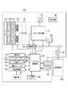
図1にデジタルカメラの外観図を示す。表示部28は画像や各種情報を表示する表示部であり、立体表示可能となっている。シャッターボタン61は撮影指示を行うための操作部である。モードダイアル60は各種モードを切り替えるための操作部である。コネクタ112は接続ケーブルとデジタルカメラ100とのコネクタである。操作部70はユーザーからの各種操作を受け付ける各種スイッチ、ボタンより成る操作部である。表示部28は不図示のタッチパネルを備えており、操作部70の一つとして機能する。また、コントローラーホイール73も操作部70に含まれており、回転操作可能な操作部材である。72は電源スイッチであり、電源オン、電源オフを切り替える。記録媒体は200はメモリカードやハードディスク等の記録媒体である。記録媒体スロット201は記録媒体200を格納するためのスロットである。記録媒体スロット201に格納された記録媒体200は、デジタルカメラ100との通信が可能となる。蓋202は記録媒体スロット201の蓋である。 FIG. 1 shows an external view of a digital camera. The
図2は、本実施形態によるデジタルカメラ100の構成例を示すブロック図である。 FIG. 2 is a block diagram illustrating a configuration example of the
図2において、103はフォーカスレンズを含む撮影レンズ、101は絞り機能を備えるシャッター、22は光学像を電気信号に変換するCCDやCMOS素子等で構成される撮像部である。撮影レンズ103、シャッター101、撮像部22は、立体画像用に左右それぞれの眼に対する信号を生成するため、2個ずつ備えている。23はA/D変換器であり、アナログ信号をデジタル信号に変換する。A/D変換器23は、撮像部22から出力されるアナログ信号をデジタル信号に変換するために用いられる。102はバリアであり、デジタルカメラ100の、撮影レンズ103を含む撮像部を覆うことにより、撮影レンズ103、シャッター101、撮像部22を含む撮像系の汚れや破損を防止する。 In FIG. 2,
24は画像処理部であり、A/D変換器23からのデータ、又は、メモリ制御部15からのデータに対し所定の画素補間、縮小といったリサイズ処理、色変換処理等を行う。また、画像処理部24では、撮像した画像データを用いて所定の演算処理が行われ、得られた演算結果に基づいてシステム制御部50が露光制御、測距制御を行う。これにより、TTL(スルー・ザ・レンズ)方式のAF(オートフォーカス)処理、AE(自動露出)処理、EF(フラッシュプリ発光)処理が行われる。画像処理部24では更に、撮像した画像データを用いて所定の演算処理を行い、得られた演算結果に基づいてTTL方式のAWB(オートホワイトバランス)処理も行っている。 An image processing unit 24 performs resize processing such as predetermined pixel interpolation and reduction, color conversion processing, and the like on the data from the A /
また、画像処理部24は、左右のそれぞれの眼に対応させた、立体視が可能な3次元画像データを生成する。 In addition, the image processing unit 24 generates three-dimensional image data that can be viewed stereoscopically, corresponding to the left and right eyes.
A/D変換器23からの出力データは、画像処理部24及びメモリ制御部15を介して、或いは、メモリ制御部15を介してメモリ32に直接書き込まれる。メモリ32は、撮像部22によって得られA/D変換器23によりデジタルデータに変換された画像データや、表示部28に表示するための画像データを格納する。メモリ32は、所定枚数の静止画像や所定時間の動画像および音声を格納するのに十分な記憶容量を備えている。 Output data from the A /
また、メモリ32は画像表示用のメモリ(ビデオメモリ)を兼ねている。13はD/A変換器であり、メモリ32に格納されている画像表示用のデータをアナログ信号に変換して表示部28に供給する。こうして、メモリ32に書き込まれた表示用の画像データはD/A変換器13を介して表示部28により表示される。表示部28は、LCD等の表示器上に、D/A変換器13からのアナログ信号に応じた表示を行う。A/D変換器23によって一度A/D変換されメモリ32に蓄積されたデジタル信号をD/A変換部13においてアナログ変換し、表示部28に逐次転送して表示することで、電子ビューファインダ(スルー画像表示)として機能する。 The
不揮発性メモリ56は、電気的に消去・記録可能なメモリであり、例えばEEPROM等が用いられる。不揮発性メモリ56には、システム制御部50の動作用の定数、プログラム等が記憶される。ここでいう、プログラムとは、本実施形態にて後述する各種フローチャートを実行するためのプログラムも含んでいる。 The
50はシステム制御部であり、デジタルカメラ100全体を制御する。前述した不揮発性メモリ56に記録されたプログラムを読み出して実行することで、後述する本実施形態の各処理を実現する。52はシステムメモリであり、RAMが用いられる。システムメモリ52には、システム制御部50の動作用の定数、変数、不揮発性メモリ56から読み出したプログラム等を展開し記憶している。また、システム制御部50はメモリ32、D/A変換器13、表示部28等を制御することにより表示制御も行う。
システムタイマー53は各種制御に用いる時間や、内蔵された時計の時間を計測する計時部である。 The
モード切替スイッチ60、第1シャッタースイッチ61、第2シャッタースイッチ62、操作部70はシステム制御部50に各種の動作指示を入力するための操作手段である。 The
モード切替スイッチ60は、システム制御部50の動作モードを静止画記録モード、動画記録モード、再生モード等のいずれかに切り替える為のスイッチである。第1シャッタースイッチ61は、デジタルカメラ100に設けられたシャッターボタン61の操作途中、いわゆる半押し(撮影準備指示)でONとなり第1シャッタースイッチ信号SW1を発生する。第1シャッタースイッチ信号SW1により、AF(オートフォーカス)処理、AE(自動露出)処理、AWB(オートホワイトバランス)処理、EF(フラッシュプリ発光)処理等の動作を開始する。 The
第2シャッタースイッチ62は、シャッターボタン61の操作完了、いわゆる全押し(撮影指示)でONとなり、第2シャッタースイッチ信号SW2を発生する。システム制御部50は、第2シャッタースイッチ信号SW2により、撮像部22からの信号読み出しから記録媒体200に画像データを書き込むまでの一連の撮影処理の動作を開始する。 The
操作部70の各操作部材は、表示部28に表示される種々の機能アイコンを選択操作することなどにより、場面ごとに適宜機能が割り当てられ、各種機能ボタンとして作用する。機能ボタンとしては、例えば終了ボタン、戻るボタン、画像送りボタン、ジャンプボタン、絞込みボタン、属性変更ボタン、画像輪郭強調ボタン、フォーカス位置拡大ボタン等がある。例えば、メニューボタンが押されると各種の設定可能なメニュー画面が表示部28に表示される。利用者は、表示部28に表示されたメニュー画面と、4方向ボタンやSETボタンや、またはタッチパネル等を用いて直感的に各種設定を行うことができる。 Each operation member of the
コントローラホイール73は、操作部70に含まれる回転操作可能な操作部材であり、方向ボタンと共に選択項目を指示する際などに使用される。コントローラホイール73を回転操作すると、操作量に応じて電気的なパルス信号が発生し、このパルス信号に基づいてシステム制御部50はデジタルカメラ100の各部を制御する。このパルス信号によって、コントローラホイール73が回転操作された角度や、何回転したかなどを判定することができる。なお、コントローラホイール73は回転操作が検出できる操作部材であればどのようなものでもよい。例えば、ユーザの回転操作に応じてコントローラホイール73自体が回転してパルス信号を発生するダイヤル操作部材であってもよい。また、タッチセンサよりなる操作部材で、コントローラホイール73自体は回転せず、コントローラホイール73上でのユーザの指の回転動作などを検出するものであってもよい(いわゆる、タッチホイール)。 The
80は電源制御部であり、電池検出回路、DC−DCコンバータ、通電するブロックを切り替えるスイッチ回路等により構成され、電池の装着の有無、電池の種類、電池残量の検出を行う。また、電源制御部80は、その検出結果及びシステム制御部50の指示に基づいてDC−DCコンバータを制御し、必要な電圧を必要な期間、記録媒体200を含む各部へ供給する。 A
30は電源部であり、アルカリ電池やリチウム電池等の一次電池やNiCd電池やNiMH電池、Li電池等の二次電池、ACアダプター等からなる。18はメモリカードやハードディスク等の記録媒体200とのインターフェースである。記録媒体200は、メモリカード等の記録媒体であり、半導体メモリや磁気ディスク等から構成される。 A
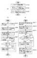
次に、図4のフローチャートに基づいて、本発明を実施したデジタルカメラ100における立体表示オブジェクトの表示方法について、説明する。 Next, a display method of a stereoscopic display object in the
本実施例では、一例として、デジタルカメラで画像データを表示する場合に、DCF(Design rule for Camera File system)で規格化されたDCFディレクトリごとにグループとして扱う場合を説明する。この時、DCFディレクトリ管理下のExif(Exchangeable Image File Format)画像ファイルを示す画像を、立体表示する際のオブジェクトとして扱う。 In the present embodiment, as an example, a case will be described in which image data is displayed by a digital camera and handled as a group for each DCF directory standardized by a DCF (Design rule for Camera File system). At this time, an image showing an Exif (Exchangeable Image File Format) image file under the management of the DCF directory is handled as an object for stereoscopic display.
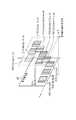
記録媒体200のDCFディレクトリ内に格納された複数のExif画像ファイルを図5(a)のように持つ場合を考える。 Consider a case where a plurality of Exif image files stored in the DCF directory of the
まず、図5(a)に示す、記録媒体200のルートディレクトリ501には、「DCIM」と名称付けられたDCFルートディレクトリ502が格納されている。DCFルートディレクトリ502には、503〜506で示されるDCFディレクトリが格納されており、それぞれのDCFディレクトリにはExif画像ファイル507〜522が格納されている。
「101ABCDE」と名称付けられたDCFディレクトリ503には、「IMG_0101.JPG」と名称付けられたExif画像ファイル507と、「IMG_0102.JPG」と名称付けられたExif画像ファイル508との2画像が格納されている。
「102ABCDE」と名称付けられたDCFディレクトリ504には、「IMG_0201.JPG」と名称付けられたExif画像ファイル509から「IMG_0203.JPG」と名称付けられたExif画像ファイル511の3画像が格納されている。
「103ABCDE」と名称付けられたDCFディレクトリ505には、「IMG_0301.JPG」と名称付けられたExif画像ファイル512から、「IMG_0305.JPG」と名称付けられたExif画像ファイル516の5画像が格納されている。
「104ABCDE」と名称付けられたDCFディレクトリ506には、「IMG_0401.JPG」と名称付けられたExif画像ファイル517から、「IMG_0406.JPG」と名称付けられたExif画像ファイル522の6画像が格納されている。First, the
The
The
The
The
まず、記録媒体200がデジタルカメラ100の記録媒体スロット201に挿入され、FAT(File Allocation Table)などに代表されるファイルシステムの解析処理を終了した際に行われる処理について説明する。 First, processing performed when the
S401において、記録媒体200内のオブジェクトのグループを検出する。ここでは、システム制御部50は、記録媒体200からDCFディレクトリを検索してメモリ32に各DCFディレクトリのDCFディレクトリ番号を格納し、S402に進む。 In step S401, a group of objects in the
次に、S402において、各グループに属するオブジェクトを検出する。ここでは、システム制御部50は、メモリ32に格納された各DCFディレクトリを参照し、各DCFディレクトリに格納されているExif画像ファイルを検索して、S403に進む。 Next, in S402, an object belonging to each group is detected. Here, the
次にS403において、システム制御部50は、検索されたExif画像ファイルのDCFファイル番号を、メモリ32に格納された各DCFディレクトリのDCFディレクトリ番号に関連付けて、メモリ32に後述する格納形式で保存する。 In step S <b> 403, the
S401で検索されたDCFディレクトリは、図5(b)のメモリマップに示すように、格納される。具体的には、503のDCFディレクトリ番号「101」がメモリ32上のアドレス0xbfa0_0000番地から2byteの領域を使用して格納される。そして、504のDCFディレクトリ番号「102」がメモリ32のアドレス0xbfa0_0008番地から、505のDCFディレクトリ番号「103」がメモリ32のアドレス0xbfa0_0010番地からそれぞれ2byteの領域を使用して格納される。また、506のDCFディレクトリ番号「104」がメモリ32上のアドレス0xbfa0_0018番地から2byteの領域を使用して格納される。 The DCF directory searched in S401 is stored as shown in the memory map of FIG. Specifically, the DCF directory number “101” of 503 is stored using an area of 2 bytes from address 0xbfa0_0000 on the
また、S402で検索されたExif画像ファイルは、図5(b)のようにメモリ32で管理される。具体的には、ディレクトリ503に格納された画像ファイル507〜508のDCFファイル番号はアドレス0xbfa0_0100から各ファイル番号につき2byteの領域を使用して順次格納される。そして、ディレクトリ503内の最初の画像ファイル507のアドレス0xbfa0_0100をアドレス0xbfa0_0004に格納する。また、ディレクトリ503に格納された画像ファイル507〜508の個数である2をアドレス0xbfa0_0002に格納する。 The Exif image file searched in S402 is managed in the
また、ディレクトリ504に格納された画像ファイル509〜511のDCFファイル番号は画像ファイル507〜508のDCFファイル番号の格納領域の次のアドレスである0xbfa0_0104から各ファイル番号につき2byteの領域を使用して順次格納される。そして、ディレクトリ504内の最初の画像ファイル509のアドレス0xbfa0_0104は、アドレス0xbfa0_000cに格納される。また、DCFディレクトリ504に格納されたExif画像ファイル509〜511の個数である3が、アドレス0xbfa0_000aに格納される。 In addition, the DCF file numbers of the image files 509 to 511 stored in the
また、ディレクトリ505に格納された画像ファイル512〜516のDCFファイル番号は画像ファイル509〜511のDCFファイル番号の格納領域の次のアドレス領域である0xbfa0_010aから各ファイル番号につき2byteの領域を使用して順次格納される。そして、ディレクトリ内の最初の画像ファイル512のアドレス0xbfa0_010aが、アドレス0xbfa0_0014に格納される。また、ディレクトリ505に格納された画像ファイル512〜516の個数である5がアドレス0xbfa0_0012に格納される。 Also, the DCF file numbers of the image files 512 to 516 stored in the
また、ディレクトリ506に格納された画像ファイル517〜522のDCFファイル番号は、画像ファイル512〜516のDCFファイル番号の格納領域の次の0xbfa0_0114から各ファイル番号につき2byteの領域を使用して順次格納される。そして、ディレクトリ内の最初の画像ファイル517のアドレス0xbfa0_0114は0xbfa0_001cに格納される。また、DCFディレクトリ503に格納された画像ファイル507〜508の個数である6がアドレス0xbfa0_001aに格納される。 Also, the DCF file numbers of the image files 517 to 522 stored in the
次に、上述したS401〜S403の処理の後、Exif画像の再生画面においてサムネイル再生処理を行う際の処理について説明する。 Next, processing when performing thumbnail reproduction processing on the Exif image reproduction screen after the above-described processing of S401 to S403 will be described.
S404において、システム制御部50は、表示するグループを決定する。デジタルカメラ100の例では、システム制御部50が図5(b)の情報を参照して、どのディレクトリを表示対象とするかを決定する。なおこの決定は、使用者の操作部への操作により、表示するディレクトリを操作、設定することで決定される。画像表示時の最初では、番号の若いDCFディレクトリから順番に3つのディレクトリDCFディレクトリ503〜505に格納されたExif画像ファイルを表示すると決定される。 In S404, the
次に、S405において、表示するグループの先頭の画像の表示位置を決定する。デジタルカメラ100の例では、システム制御部50は、上述したS404において決定された3つのDCFディレクトリの先頭の画像を表示部28の面内のどの位置に表示するかを決定する。 In step S405, the display position of the first image in the group to be displayed is determined. In the example of the
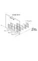
ここで一例として、図6(a)のように、面内座標にDCFディレクトリ503〜505の先頭の画像の中心座標を、それぞれ(Ax,Ay)、(Bx,By)、(Cx,Cz)の座標に配置するとする。 Here, as an example, as shown in FIG. 6A, the center coordinates of the head images of the
次に、S406において、システム制御部50は、表示すると決定されたディレクトリのうちの最初のDCFディレクトリ(上記説明ではDCFディレクトリ503)へ参照先を設定して、S407に進む。 Next, in S406, the
次に、S407において、システム制御部50は、参照先のDCFディレクトリに対して、図4(c)のフローチャートに記載された表示位置算出処理を行う。 In step S <b> 407, the
まず、S4071において、システム制御部50は、表示部で画像を配置して表示する場合の奥行き方向の表示範囲を取得する。 First, in S4071, the
なお、この奥行き方向の表示範囲は、表示部28の物理的、または、電気的特性から求められた固定値でも良いし、表示部28に表示する画面により画面毎の表示範囲テーブルとして各々の表示範囲の値を持ち、これを参照しても良い。 The display range in the depth direction may be a fixed value obtained from the physical or electrical characteristics of the
ここでは、一例として表示範囲を固定値として設定することとし、表示部の平面から奥行き方向αの間で表示を行うとして、奥行き0〜αを表示範囲として設定する。このαに応じて、右目用画像と左目用画像との間の視差量が変化することになる。 Here, the display range is set as a fixed value as an example, and the display is performed between the plane of the display unit and the depth direction α, and the
ここでDCFディレクトリ503から505の、最前面画像の座標は、それぞれ(Ax,Ay,0)、(Bx,By,0)、(Cx,Cz,0)の座標に決定される。 Here, the coordinates of the foreground image in the
次に、S4072において、システム制御部50は、参照先DCFディレクトリ内のうち、表示部28の最前面に表示する画像ファイルを参照先のオブジェクトとして設定してする。 In step S4072, the
例えば、DCFディレクトリ503が参照先DCFディレクトリであればメモリ32上のアドレス0xbfa0_0004の指示するアドレス0xbfa0_0100に格納されたデータ「0101」より画像ファイル507が参照される。DCFディレクトリ505が参照先DCFディレクトリの時には、メモリ32上のアドレス0xbfa0_000cの指示するアドレス0xbfa0_0104に格納されたデータ「0201」よりExif画像ファイル507が、参照される。DCFディレクトリ506が参照先DCFディレクトリであればメモリ32上のアドレス0xbfa0_0014の指示するアドレス0xbfa0_010aに格納されたデータ「0301」よりExif画像ファイル507が参照される。参照先として設定された画像ファイルは、画像データまたはサムネールデータが表示オブジェクトとして読みだされる。なお、ユーザが操作部70により操作し任意の画像を最前面画像に選択するような場合には、その選択された画像ファイルを参照先として設定して表示オブジェクトとしてもよい。 For example, if the
次に、S4073において、システム制御部は、参照先のDCFディレクトリ配下に格納されたExif画像ファイルの個数をメモリ32から取得して、立体表示オブジェクトの奥行き方向の位置(座標)を求め、S4074に進む。 In step S4073, the system control unit obtains the number of Exif image files stored under the DCF directory of the reference destination from the
参照先のDCFディレクトリ配下に格納されたExif画像ファイルの個数は、例えば、DCFディレクトリ503の場合には2で、DCFディレクトリ504の場合には3で、DCFディレクトリ505の場合には5が取得される。 The number of Exif image files stored under the reference DCF directory is, for example, 2 for the
また、奥行き方向の位置(座標)を求める計算式の一例として、計算式:α×(i−1)/nの計算式から算出し、Exif画像ファイルの奥行き方向座標をメモリ32上のアドレス0xbfa0_0200から順次、各2byteの領域を使用して格納する。 Further, as an example of a calculation formula for obtaining the position (coordinates) in the depth direction, the calculation formula: α × (i−1) / n is used to calculate the depth direction coordinates of the Exif image file at the address 0xbfa0 — 0200 on the
この式により、グループ毎に、複数の画像間の表示間隔を決定することが出来るとともに、奥行き座標も決定することが出来る。 With this equation, the display interval between a plurality of images can be determined for each group, and the depth coordinate can also be determined.
なお、上記の計算式のiは、参照先のExif画像ファイルがグループ内の先頭から何番目に属するかを示す。 Note that i in the above calculation formula indicates what number the reference Exif image file belongs to from the top in the group.
また、計算式のnは各グループ内の画像ファイルの数と、後述するS4074で使用する、奥行きα内に配置可能とする画像の上限値から1を引いた数とのいずれか小さい値を示す。 In addition, n in the calculation formula indicates a smaller value of either the number of image files in each group or the number obtained by subtracting 1 from the upper limit value of images that can be arranged within the depth α used in S4074 described later. .
本実施例では、最前面に表示する画像ファイルを含めて前から5枚目までを立体表示を行い、6枚目からは立体表示を行わないとする。この場合、奥行きαに配置される画像の上限値は5枚であある。 In the present embodiment, it is assumed that stereoscopic display is performed for the fifth image from the front including the image file to be displayed on the foreground, and stereoscopic display is not performed for the sixth image. In this case, the upper limit value of images arranged at the depth α is five.
次に、S4074において、システム制御部50は、参照している画像ファイルの次の画像ファイルが立体表示するオブジェクトであるか否かを判定する。本実施例では各グループの先頭から5枚以内の画像ファイルであるかを判定することになる。 In step S4074, the
なお奥行きα内に配置する画像の数は固定値としたが、表示モードや表示する画像のサイズに応じて可変的にしても良いし、使用者の設定等により決めてもよい。 Although the number of images arranged in the depth α is a fixed value, it may be variable depending on the display mode and the size of the image to be displayed, or may be determined by user settings or the like.
上記処理の判定の結果、立体表示する場合にはS4075に進み、立体表示しない場合にはS6076に進む。 As a result of the determination of the above processing, if stereoscopic display is performed, the process proceeds to S4075.
次に、S4075において、システム制御部50は、参照先のDCFディレクトリの配下に配置されたExif画像ファイルのうち、次に若いDCFファイル番号を持つExif画像ファイルを参照先の表示オブジェクトとして設定し、S4073に戻る。 Next, in S4075, the
次に、S4076において、システム制御部50は、奥行き位置を決定していない残りのオブジェクトについて、最も奥に表示したオブジェクトと同一の奥行き座標に表示するよう設定を行う。今回の説明では6枚目以降の画像を、5枚目の画像と同じ奥行きの位置に表示するように設定することになる。 In step S4076, the
上記処理は、例えば、システム制御部50がDCFディレクトリ506を表示する際に、最前面から5枚目のExif画像ファイル521と奥行き方向では同じ位置に6枚目のExif画像ファイル522の奥行き位置を設定する。この時、Exif画像ファイル0522を表示するサイズを、5枚目の画像ファイル再生の表示の大きさよりも一定割合で小さくしても良い。または、6枚目以降の画像を非表示にするように変形してもよいであろう。 For example, when the
上述したS407の処理を行った後、S408において、参照先のDCFディレクトリの次に若いDCFディレクトリ番号を持つDCFディレクトリがS404で表示対象と決定したディレクトリか否かを判定する。上記の判定の結果、参照先のDCFディレクトリの次に若いDCFディレクトリ番号を持つDCFディレクトリを表示する場合にはS409に進み、表示しない場合には処理を終了する。 After performing the processing of S407 described above, in S408, it is determined whether or not the DCF directory having the next youngest DCF directory number after the reference destination DCF directory is the directory determined as the display target in S404. As a result of the above determination, if a DCF directory having the next lowest DCF directory number after the reference destination DCF directory is to be displayed, the process proceeds to S409, and if not, the process ends.
S409において、参照先のDCFディレクトリの次に若いDCFディレクトリ番号を持つDCFディレクトリを新たに参照先のDCFディレクトリとして設定して、S407に戻る。 In step S409, the DCF directory having the next lowest DCF directory number after the reference destination DCF directory is newly set as the reference destination DCF directory, and the process returns to step S407.
図4(b)、(c)の処理の結果、それぞれ図5(b)のメモリマップに表されるように、DCFディレクトリ503の配下に格納されている、Exif画像ファイル507の奥行き位置は0、Exif画像ファイル508の奥行き位置はα、となる。また、DCFディレクトリ504の配下に格納されている、Exif画像ファイル509の奥行き位置は0、Exif画像ファイル510の奥行き位置はα/2、Exif画像ファイル511の奥行き位置はα、となる。また、DCFディレクトリ505の配下に格納されている、Exif画像ファイル512の奥行き位置は0、Exif画像ファイル513の奥行き位置はα/4、Exif画像ファイル514の奥行き位置はα/2、Exif画像ファイル515の奥行き位置は(3α)/4、Exif画像ファイル516の奥行き位置はα、となる。 As a result of the processing of FIGS. 4B and 4C, the depth position of the
上述した、S401〜S408の処理によって決定された奥行き方向の表示位置に基づき、システム制御部50は、図6に示したように表示部28上にExif画像ファイル507〜516を表示する。 Based on the display position in the depth direction determined by the processing of S401 to S408 described above, the
Exif画像ファイル507は、S4072において決定されたDCFディレクトリ503の面内座標(Ax,Ay,0)の位置に配置する。 The
さらに、Exif画像ファイル508は、奥行き位置αとし、さらに、後方のExif画像ファイルの視認性を向上させるために、y軸方向に奥行き位置をβ/α倍した値であるβをずらすので(Ax,Ay+β,α)に表示を行う。 Further, the
また、Exif画像ファイル509は、S4072において決定されたDCFディレクトリ504の面内座標(Bx,By,0)の位置に配置する。 Further, the
さらに、Exif画像ファイル510は、奥行き位置α/2となり、さらに、後方のExif画像ファイルの視認性を向上させるため、y軸方向にも奥行き位置をβ/α倍した値であるβ/2ずらすので、(Ax,Ay+β/2,α/2)に表示を行う。 Further, the
さらに、Exif画像ファイル511は、画像ファイル510からさらに奥行き位置α/2を加え、さらに、後方のExif画像ファイルの視認性を向上させるため、y軸方向の座標は奥行き位置をβ/α倍した値であるβずらすので、(Ax,Ay+β,α)に表示を行う。 Further, the
また、Exif画像ファイル512は、S4072において決定されたDCFディレクトリ505の面内座標(Cx,Cy,0)の位置に配置する。 The
さらに、Exif画像ファイル513は、奥行き位置α/4となり、さらに、後方のExif画像ファイルの視認性を向上させるため、y軸方向にも奥行き位置をβ/α倍した値であるβ/4ずらすので、(Ax,Ay+β/4,α/4)に表示を行う。 Further, the
さらに、Exif画像ファイル514は、奥行き位置α/2であり、さらに、後方のExif画像ファイルの視認性を向上させるため、y軸方向にも奥行き位置をβ/α倍した値であるβ/2ずらすので、(Ax,Ay+β/2,α/2)に表示を行う。 Further, the
さらに、Exif画像ファイル515は、奥行き位置3α/4であり、さらに、後方のExif画像ファイルの視認性を向上させるため、y軸方向にも奥行き位置をβ/α倍した値である3β/4ずらすので、(Ax,Ay+3β/4,3α/4)に表示を行う。 Further, the
さらに、Exif画像ファイル516は、奥行き位置αであり、さらに、後方のExif画像ファイルの視認性を向上させるため、y軸方向にも奥行き位置をβ/α倍した値であるβずらすので、(Ax,Ay+β,α)に表示を行う。 Further, the
上述した処理により仮想空間上に、グループ毎にオブジェクトを配置する場合に、各グループ毎にオブジェクト間(画像間)の表示間隔を決定することが出来る。これにより、全グループで画像間を等間隔に配置する場合よりも、一定の視差量内で利用者が各グループの画像を視認することができる。 When an object is arranged for each group in the virtual space by the above-described processing, a display interval between objects (between images) can be determined for each group. Thereby, a user can visually recognize the image of each group within a fixed amount of parallax, compared with the case where images are arranged at equal intervals in all groups.
ただし、本件は、グループ化された表示オブジェクトの表示方法に関するため、表示対象としてはExif画像ファイル以外でも良い。例えば、映像ストリームの単位時間毎のフレーム画像を一覧表示するタイムライン表示などを表示オブジェクトとしてもよい。この場合、各映像ストリームを1グループとして割り当て、さらに、各映像ストリームに属する単位時間毎のフレーム画像を表示オブジェクトとして割り当てることで、同様の表示を行うことが可能である。 However, since this case relates to a display method for grouped display objects, the display target may be other than an Exif image file. For example, the display object may be a timeline display that displays a list of frame images for each unit time of the video stream. In this case, it is possible to perform the same display by assigning each video stream as one group and further assigning a frame image per unit time belonging to each video stream as a display object.
また、さらには表示オブジェクトとしてはアイコンデータや文字情報等でもよい。例えば、メニューの表示に適用した場合、各設定の種類ごとにグループとして割り当て、各設定の種類に含まれる詳細な選択肢を示すアイコンや文字を表示オブジェクトとして割り当てることで、同様の表示を行うことが可能である。 Further, the display object may be icon data, character information, or the like. For example, when applied to menu display, the same display can be performed by assigning each setting type as a group and assigning icons and characters indicating detailed options included in each setting type as display objects. Is possible.
また上記では、Exif画像ファイル、および、DCFの規格を一例として挙げるためデジタルカメラを例として説明したが、パーソナルコンピュータやテレビ等の撮像を行わない表示装置においても実施可能である。 In the above description, the digital camera has been described as an example in order to take the Exif image file and the DCF standard as an example. However, the present invention can also be implemented in a display device that does not perform imaging such as a personal computer or a television.
以上、本発明をその好適な実施形態に基づいて詳述してきたが、本発明はこれら特定の実施形態に限られるものではなく、この発明の要旨を逸脱しない範囲の様々な形態も本発明に含まれる。上述の実施形態の一部を適宜組み合わせてもよい。 Although the present invention has been described in detail based on preferred embodiments thereof, the present invention is not limited to these specific embodiments, and various forms within the scope of the present invention are also included in the present invention. included. A part of the above-described embodiments may be appropriately combined.
例えば、上記の画像の配置の方法は一例であり、適宜の修正を加えても良く、また上記の計算式も一例であり、適宜計算式の修正を加えても良く、本発明の範囲が制約されることを示すものではない。 For example, the above-described image arrangement method is an example, and appropriate correction may be made. Also, the above calculation formula may be an example, and the calculation formula may be appropriately corrected, and the scope of the present invention is limited. It does not indicate that it will be done.
また、上述の実施形態の機能を実現するソフトウェアのプログラムを、記録媒体から直接、或いは有線/無線通信を用いてプログラムを実行可能なコンピュータを有するシステム又は装置に供給し、そのプログラムを実行する場合も本発明に含む。 Also, when a software program that realizes the functions of the above-described embodiments is supplied from a recording medium directly to a system or apparatus having a computer that can execute the program using wired / wireless communication, and the program is executed Are also included in the present invention.
従って、本発明の機能処理をコンピュータで実現するために、該コンピュータに供給、インストールされるプログラムコード自体も本発明を実現するものである。つまり、本発明の機能処理を実現するためのコンピュータプログラム自体も本発明に含まれる。 Accordingly, the program code itself supplied and installed in the computer in order to implement the functional processing of the present invention by the computer also realizes the present invention. That is, the computer program itself for realizing the functional processing of the present invention is also included in the present invention.
その場合、プログラムの機能を有していれば、オブジェクトコード、インタプリタにより実行されるプログラム、OSに供給するスクリプトデータ等、プログラムの形態を問わない。 In this case, the program may be in any form as long as it has a program function, such as an object code, a program executed by an interpreter, or script data supplied to the OS.
プログラムを供給するための記録媒体としては、例えば、ハードディスク、磁気テープ等の磁気記録媒体、光/光磁気記憶媒体、不揮発性の半導体メモリでもよい。 As a recording medium for supplying the program, for example, a magnetic recording medium such as a hard disk or a magnetic tape, an optical / magneto-optical storage medium, or a nonvolatile semiconductor memory may be used.
また、プログラムの供給方法としては、コンピュータネットワーク上のサーバに本発明を形成するコンピュータプログラムを記憶し、接続のあったクライアントコンピュータはがコンピュータプログラムをダウンロードしてプログラムするような方法も考えられる。 As a program supply method, a computer program that forms the present invention is stored in a server on a computer network, and a connected client computer downloads and programs the computer program.
Claims (10)
Translated fromJapaneseグループ毎に複数の画像を奥行き方向に配置する場合に、各グループの奥行き方向の表示範囲を一定の視差量内となるように、各グループに含まれる画像の枚数に応じて、同一のグループに属する複数の画像間の表示間隔を前記グループ毎に決定する決定手段と、
前記決定手段で決定したグループ毎の表示間隔に基づき、前記複数の画像を奥行き方向に配置して前記表示装置に表示させる表示制御手段とを有することを特徴とする表示制御装置。A display control device for arranging a plurality of images at a predetermined interval in the depth direction of stereoscopic display and displaying the images on a display device capable of stereoscopic display,
When multiple images are arranged in the depth direction for each group, the same group is assigned according to the number of images includedin each groupso that the display range in the depth direction of each group is within a certain amount of parallax. Determining means for determining a display interval between a plurality of images belonging to each group;
A display control device comprising: display control means for arranging the plurality of images in the depth direction and displaying them on the display device based on the display interval for each group determined by the determination means.
グループ毎に複数の画像を奥行き方向に配置する場合に、各グループの奥行き方向の表示範囲を一定の視差量内となるように、各グループに含まれる画像の枚数に応じて、同一のグループに属する複数の画像間の表示間隔を前記グループ毎に決定する決定工程と、
前記決定工程で決定したグループ毎の表示間隔に基づき、前記複数の画像を奥行き方向に配置して前記表示装置に表示させる表示制御工程とを有することを特徴とする表示制御方法。A display control method for arranging a plurality of images at a predetermined interval in the depth direction of stereoscopic display and displaying the images on a display device capable of stereoscopic display,
When multiple images are arranged in the depth direction for each group, the same group is assigned according to the number of images includedin each groupso that the display range in the depth direction of each group is within a certain amount of parallax. A determination step of determining a display interval between a plurality of images belonging to each group;
Display control method characterized by comprising a display control step of the decision based on the display intervals of determined groups in step,by arranging the plurality of images in the depth direction is displayed on the display device.
Priority Applications (2)
| Application Number | Priority Date | Filing Date | Title |
|---|---|---|---|
| JP2011086515AJP5792983B2 (en) | 2011-04-08 | 2011-04-08 | Display control apparatus and display control method |
| US13/439,710US8947426B2 (en) | 2011-04-08 | 2012-04-04 | Display control apparatus and display control method |
Applications Claiming Priority (1)
| Application Number | Priority Date | Filing Date | Title |
|---|---|---|---|
| JP2011086515AJP5792983B2 (en) | 2011-04-08 | 2011-04-08 | Display control apparatus and display control method |
Publications (3)
| Publication Number | Publication Date |
|---|---|
| JP2012222618A JP2012222618A (en) | 2012-11-12 |
| JP2012222618A5 JP2012222618A5 (en) | 2014-05-22 |
| JP5792983B2true JP5792983B2 (en) | 2015-10-14 |
Family
ID=46965737
Family Applications (1)
| Application Number | Title | Priority Date | Filing Date |
|---|---|---|---|
| JP2011086515AExpired - Fee RelatedJP5792983B2 (en) | 2011-04-08 | 2011-04-08 | Display control apparatus and display control method |
Country Status (2)
| Country | Link |
|---|---|
| US (1) | US8947426B2 (en) |
| JP (1) | JP5792983B2 (en) |
Families Citing this family (3)
| Publication number | Priority date | Publication date | Assignee | Title |
|---|---|---|---|---|
| JP2013016116A (en)* | 2011-07-06 | 2013-01-24 | Sony Corp | Information processing device, image display apparatus, and information processing method |
| JP6364836B2 (en)* | 2014-03-14 | 2018-08-01 | セイコーエプソン株式会社 | Robot, robot system, and control device |
| CN107480269B (en)* | 2017-08-17 | 2021-01-22 | 阿里巴巴(中国)有限公司 | Object display method and system, medium and computing equipment |
Family Cites Families (4)
| Publication number | Priority date | Publication date | Assignee | Title |
|---|---|---|---|---|
| JP2005071332A (en) | 2003-08-04 | 2005-03-17 | Matsushita Electric Ind Co Ltd | Portable terminal device and image display method |
| JP4458158B2 (en)* | 2007-12-07 | 2010-04-28 | ソニー株式会社 | Display device, display method, and program |
| JP5575388B2 (en)* | 2008-12-03 | 2014-08-20 | 株式会社東芝 | Image display apparatus and X-ray CT apparatus |
| KR101622307B1 (en)* | 2009-07-02 | 2016-05-18 | 삼성전자주식회사 | Three-dimensional image display apparatus and method |
- 2011
- 2011-04-08JPJP2011086515Apatent/JP5792983B2/ennot_activeExpired - Fee Related
- 2012
- 2012-04-04USUS13/439,710patent/US8947426B2/enactiveActive
Also Published As
| Publication number | Publication date |
|---|---|
| JP2012222618A (en) | 2012-11-12 |
| US20120256913A1 (en) | 2012-10-11 |
| US8947426B2 (en) | 2015-02-03 |
Similar Documents
| Publication | Publication Date | Title |
|---|---|---|
| JP6529267B2 (en) | INFORMATION PROCESSING APPARATUS, CONTROL METHOD THEREOF, PROGRAM, AND STORAGE MEDIUM | |
| US9819857B2 (en) | Electronic apparatus, control method for the same, and image capturing apparatus | |
| JP7183033B2 (en) | ELECTRONIC DEVICE, ELECTRONIC DEVICE CONTROL METHOD, PROGRAM, AND STORAGE MEDIUM | |
| US12406330B2 (en) | Electronic apparatus, control method of electronic apparatus, and non-transitory computer readable medium | |
| KR20190079536A (en) | Electronic apparatus | |
| JP5792983B2 (en) | Display control apparatus and display control method | |
| JP6857044B2 (en) | Display control device, its control method, program and recording medium | |
| JP7034619B2 (en) | Image pickup device, its control method, and program, and storage medium | |
| JP2012220840A (en) | Image display device and image display method | |
| JP7191649B2 (en) | Electronics | |
| JP6968690B2 (en) | Electronics | |
| JP6851738B2 (en) | Display control device, its control method, program, and storage medium | |
| JP2022191143A (en) | Image processing device and image processing method | |
| JP7098495B2 (en) | Image processing device and its control method | |
| US20200336694A1 (en) | Data transfer apparatus and control method thereof | |
| JP6873792B2 (en) | Imaging control device and its control method | |
| JP2012010344A (en) | Image processing apparatus, method and program | |
| JP2013247478A (en) | Image pickup device, control method and program thereof, and recording medium | |
| JP2020167623A (en) | Imaging device and control method | |
| JP2020057845A (en) | Editing device, control method thereof, and program | |
| JP7005340B2 (en) | Electronics | |
| JP6625113B2 (en) | Electronics | |
| JP6611478B2 (en) | Imaging apparatus, recording control method, and program | |
| JP2025125223A (en) | Electronic device, electronic device control method, and program | |
| JP2016082276A (en) | Imaging device |
Legal Events
| Date | Code | Title | Description |
|---|---|---|---|
| A521 | Request for written amendment filed | Free format text:JAPANESE INTERMEDIATE CODE: A523 Effective date:20140408 | |
| A621 | Written request for application examination | Free format text:JAPANESE INTERMEDIATE CODE: A621 Effective date:20140408 | |
| A977 | Report on retrieval | Free format text:JAPANESE INTERMEDIATE CODE: A971007 Effective date:20141205 | |
| A131 | Notification of reasons for refusal | Free format text:JAPANESE INTERMEDIATE CODE: A131 Effective date:20141216 | |
| A521 | Request for written amendment filed | Free format text:JAPANESE INTERMEDIATE CODE: A523 Effective date:20150216 | |
| TRDD | Decision of grant or rejection written | ||
| A01 | Written decision to grant a patent or to grant a registration (utility model) | Free format text:JAPANESE INTERMEDIATE CODE: A01 Effective date:20150714 | |
| A61 | First payment of annual fees (during grant procedure) | Free format text:JAPANESE INTERMEDIATE CODE: A61 Effective date:20150807 | |
| R151 | Written notification of patent or utility model registration | Ref document number:5792983 Country of ref document:JP Free format text:JAPANESE INTERMEDIATE CODE: R151 | |
| LAPS | Cancellation because of no payment of annual fees |