JP5789736B2 - Power supply - Google Patents
Power supplyDownload PDFInfo
- Publication number
- JP5789736B2 JP5789736B2JP2009244963AJP2009244963AJP5789736B2JP 5789736 B2JP5789736 B2JP 5789736B2JP 2009244963 AJP2009244963 AJP 2009244963AJP 2009244963 AJP2009244963 AJP 2009244963AJP 5789736 B2JP5789736 B2JP 5789736B2
- Authority
- JP
- Japan
- Prior art keywords
- secondary battery
- soc
- time
- capacity
- charge
- Prior art date
- Legal status (The legal status is an assumption and is not a legal conclusion. Google has not performed a legal analysis and makes no representation as to the accuracy of the status listed.)
- Active
Links
Images


Classifications
- G—PHYSICS
- G01—MEASURING; TESTING
- G01R—MEASURING ELECTRIC VARIABLES; MEASURING MAGNETIC VARIABLES
- G01R31/00—Arrangements for testing electric properties; Arrangements for locating electric faults; Arrangements for electrical testing characterised by what is being tested not provided for elsewhere
- G01R31/36—Arrangements for testing, measuring or monitoring the electrical condition of accumulators or electric batteries, e.g. capacity or state of charge [SoC]
- G01R31/392—Determining battery ageing or deterioration, e.g. state of health
- G—PHYSICS
- G01—MEASURING; TESTING
- G01R—MEASURING ELECTRIC VARIABLES; MEASURING MAGNETIC VARIABLES
- G01R31/00—Arrangements for testing electric properties; Arrangements for locating electric faults; Arrangements for electrical testing characterised by what is being tested not provided for elsewhere
- G01R31/36—Arrangements for testing, measuring or monitoring the electrical condition of accumulators or electric batteries, e.g. capacity or state of charge [SoC]
- G01R31/385—Arrangements for measuring battery or accumulator variables
- G01R31/386—Arrangements for measuring battery or accumulator variables using test-loads
Landscapes
- Physics & Mathematics (AREA)
- General Physics & Mathematics (AREA)
- Charge And Discharge Circuits For Batteries Or The Like (AREA)
- Secondary Cells (AREA)
- Tests Of Electric Status Of Batteries (AREA)
- Stand-By Power Supply Arrangements (AREA)
Description
Translated fromJapanese本発明は、電力供給装置に関するものである。 The present invention relates to a power supply device.
二次電池を停電時のバックアップ電源として用い、停電時には二次電池から負荷機器へ電力を供給する電力供給装置がある(例えば、特許文献1参照)。 There is a power supply device that uses a secondary battery as a backup power source in the event of a power failure and supplies power from the secondary battery to a load device during a power failure (see, for example, Patent Document 1).
二次電池は、使用時間の増加に伴って容量(Wh)が減少するため定期的に交換が必要となる。例えば、携帯電話等の二次電池は常に充放電を繰り返して使用しているため、放電電気量と放電時間、または充電電気量と充電時間から容量を容易に確認できる。したがって、初期容量に対する容量の低下度合を検知して、二次電池の劣化状態を判定し、電池寿命の検出が可能となる。 Since the capacity (Wh) decreases as the usage time increases, the secondary battery needs to be replaced periodically. For example, since a secondary battery such as a mobile phone is always used by repeatedly charging and discharging, the capacity can be easily confirmed from the amount of discharge electricity and discharge time or the amount of charge electricity and charge time. Therefore, it is possible to detect the battery life by detecting the degree of decrease in the capacity with respect to the initial capacity and determining the deterioration state of the secondary battery.
一方、停電時のバックアップ電源として使用する二次電池の場合、通常は自己放電分を除いて充放電を殆ど行わないため、容量確認が困難である。さらに、停電時のバックアップ電源として用いるため、容量がゼロ近くに低下するまで放電させて容量確認を行うことはできない。而して、非停電時の使用していないときに容量確認を行って、二次電池の劣化状態を判定する必要がある。 On the other hand, in the case of a secondary battery used as a backup power source in the event of a power failure, it is difficult to check the capacity because charging and discharging are usually not performed except for self-discharge. Furthermore, since it is used as a backup power source in the event of a power failure, it cannot be confirmed by discharging until the capacity drops to near zero. Thus, it is necessary to check the capacity of the secondary battery by checking the capacity when not in use at the time of non-power failure.
二次電池の劣化状態を判定する試験方法としては、上記特許文献1のように、放電開始から所定時間経過後の二次電池の電圧に基づいて、二次電池の劣化状態を判定する方法等が従来から提案されている。しかしながら、二次電池の放電前後の電圧変動に基づいて劣化を判定するものであって、劣化状態に応じて変化する充放電時間については考慮されていないものであった。 As a test method for determining the deterioration state of the secondary battery, as in
本発明は、上記事由に鑑みてなされたものであり、その目的は、充放電時間を考慮して二次電池の劣化状態を判定可能な電力供給装置を提供することにある。 This invention is made | formed in view of the said reason, The objective is to provide the electric power supply apparatus which can determine the deterioration state of a secondary battery in consideration of charging / discharging time.
請求項1の発明は、二次電池と、二次電池を充電する充電手段と、二次電池を放電させる放電手段と、充電手段による二次電池の充電および放電手段による二次電池の放電を制御して、通常時の所定タイミングで二次電池を第1のSOCから第2のSOCまで充電させる、または通常時の所定タイミングで二次電池を第2のSOCから第1のSOCまで放電させる充放電制御手段と、充放電制御手段が二次電池を第1のSOCから第2のSOCまで充電させたとき、または充放電制御手段が二次電池を第2のSOCから第1のSOCまで放電させたときの所要時間を計測する計時手段と、計時手段の計測結果に基づいて二次電池の劣化状態を判定する判定手段とを備え、二次電池は、通常時に所定の容量以上に充電されて非常時に負荷機器へ電力を供給するバックアップ電源として用いられ、充放電制御手段は、通常時における二次電池をバックアップ保証SOC以上に充電し、判定手段によって判定された二次電池の劣化状態に応じて、通常時における二次電池が所定の容量以上となるようにバックアップ保証SOCを変動させることを特徴とする。The invention of
この発明によれば、充放電時間を考慮して二次電池の劣化状態を判定可能となる。さらに、二次電池の劣化状態に依らず、バックアップ用として必要な二次電池の容量を確保できる。According to the present invention, the deterioration state of the secondary battery can be determined in consideration of the charge / discharge time.Furthermore, the capacity of the secondary battery necessary for backup can be ensured regardless of the deterioration state of the secondary battery.
請求項2の発明は、請求項1において、前記判定手段は、所定の劣化状態の二次電池を前記第1のSOCから第2のSOCまで充電したときの前記所要時間、または所定の劣化状態の二次電池を第2のSOCから第1のSOCまで放電させたときの前記所要時間を初期所要時間として記憶し、前記計時手段の計測結果と初期所要時間とを比較することによって二次電池の劣化状態を判定することを特徴とする。 According to a second aspect of the present invention, in the first aspect of the invention, the determination unit includes the time required when the secondary battery in a predetermined deterioration state is charged from the first SOC to the second SOC, or the predetermined deterioration state. The secondary battery is stored as the initial required time when the secondary battery is discharged from the second SOC to the first SOC, and the secondary battery is compared by comparing the measurement result of the time measuring means with the initial required time. It is characterized by determining the deterioration state of the.
この発明によれば、充放電時間を初期の充放電時間と比較することで、二次電池の劣化状態を判定可能となり、判定処理の簡略化を図ることができる。 According to this invention, the deterioration state of the secondary battery can be determined by comparing the charge / discharge time with the initial charge / discharge time, and the determination process can be simplified.
請求項3の発明は、請求項1において、前記判定手段は、所定の劣化状態の二次電池が前記第2のSOCであるときの容量を初期容量として記憶し、前記計時手段の計測結果に基づいて前記第2のSOCにおける二次電池の容量を導出し、当該導出した二次電池の容量と初期容量とを比較することによって二次電池の劣化状態を判定することを特徴とする。 According to a third aspect of the present invention, in the first aspect, the determination unit stores, as an initial capacity, a capacity when the secondary battery in a predetermined deterioration state is the second SOC, and the measurement result of the time measuring unit is stored in the measurement result. Based on this, the capacity of the secondary battery in the second SOC is derived, and the degradation state of the secondary battery is determined by comparing the derived capacity of the secondary battery and the initial capacity.
この発明によれば、充放電時間に基づいて導出した二次電池の容量を初期容量と比較することで、二次電池の劣化状態を判定可能となる。 According to the present invention, the deterioration state of the secondary battery can be determined by comparing the capacity of the secondary battery derived based on the charge / discharge time with the initial capacity.
請求項4の発明は、請求項1乃至3いずれかにおいて、前記充放電制御手段は、通常時に前記二次電池のSOCの上限が100%未満となるように充放電制御し、通常時の前記所定のタイミングで二次電池を100%未満である第1のSOCから100%である第2のSOCまで充電させる、または通常時の前記所定のタイミングで二次電池を100%である第2のSOCから100%未満である第1のSOCまで放電させることを特徴とする。According to a fourth aspect of the present invention, in any one of the first to third aspects, the charge / discharge control means performs charge / discharge control so that an upper limit of the SOC of the secondary battery is less than 100% at a normal time. A secondary battery is charged from a first SOC that is less than 100% to a second SOC that is 100% at a predetermined timing, or a secondary battery that is 100% at the predetermined timing at normal time It is characterized by discharging from the SOC to a first SOC that is less than 100%.
この発明によれば、二次電池の容量劣化は、残存容量が大きいほど劣化速度が速くなるので、二次電池の劣化状態を判定するときのみSOC100(%)まで充電することで、二次電池2の長寿命化を図ることができる。 According to the present invention, since the capacity deterioration of the secondary battery increases as the remaining capacity increases, the secondary battery is charged only to SOC 100 (%) only when determining the deterioration state of the secondary battery. 2 can be extended in service life.
請求項5の発明は、請求項1乃至4いずれかにおいて、前記充放電制御手段は、通常時における二次電池をバックアップ保証SOC以上に充電し、前記二次電池の温度に応じて、通常時における二次電池が前記所定の容量以上となるようにバックアップ保証SOCを変動させることを特徴とする。
A fifth aspect of the present invention, in any one of
この発明によれば、二次電池の温度に依らず、バックアップ用として必要な二次電池の容量を確保できる。 According to this invention, the capacity of the secondary battery necessary for backup can be ensured regardless of the temperature of the secondary battery.
以上説明したように、本発明では、充放電時間を考慮して二次電池の劣化状態を判定することができるという効果がある。 As described above, the present invention has an effect that the deterioration state of the secondary battery can be determined in consideration of the charge / discharge time.
以下、本発明の実施の形態を図面に基づいて説明する。 Hereinafter, embodiments of the present invention will be described with reference to the drawings.
(実施形態1)
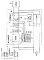
本実施形態の電力供給装置は、図1に示すように、商用電源からなる交流電源ACを直流電力にAC/DC変換して負荷機器Lに供給するコンバータ回路1(AC/DC変換手段)と、交流電源ACの停電時におけるバックアップ電源として機能する二次電池2と、交流電源ACを直流電力にAC/DC変換して二次電池2を定電流で充電する充電回路3(充電手段)と、二次電池2を放電させる放電回路4(放電手段)と、充電回路3および放電回路4の各動作を制御する充放電コントローラ5と、交流電源ACの停電を検知する停電監視回路6(停電監視手段)と、二次電池2周辺の環境温度を検出するサーミスタ7とを備える。(Embodiment 1)
As shown in FIG. 1, the power supply apparatus according to the present embodiment includes a converter circuit 1 (AC / DC conversion means) that converts an AC power source AC, which is a commercial power source, into DC power and converts the AC power into a load device L. A
充放電コントローラ5は、充放電制御部5a(充放電制御手段)と、計時部5b(計時手段)と、判定部5c(判定手段)とで構成される。停電監視回路6は、交流電源ACの電圧に基づいて停電発生を検知しており、交流電源ACの電圧が所定値より低下した場合に停電であると判断する。また、放電回路4は、二次電池2から負荷機器Lへの給電経路に直列接続された出力スイッチ4a(電源切替手段)と、二次電池2の両端間に接続された強制放電回路4b(電力消費手段)とで構成され、出力スイッチ4aは、停電監視回路6によってオン・オフ制御され、強制放電回路4bは、充放電制御部5aによって駆動制御される。 The charge /
そして、停電監視回路6が交流電源ACの停電を検知していない通常時において、負荷機器Lは、コンバータ回路1が出力する直流電力によって駆動される。充放電制御部5aは、二次電池2の電圧を所定電圧に維持するため、必要に応じて充電回路3を動作させて二次電池2を定電流充電しておく。さらに、停電監視回路6は出力スイッチ4aをオフ(開放)制御し、充放電制御部5aは強制放電回路4bを動作させる。強制放電回路4bは、二次電池2の両端間に図示しない抵抗等の擬似負荷を接続することで、強制的に二次電池2を所定量の放電状態とする機能を有しており、通常時は二次電池2を強制的に放電状態にしておくことで、後述の停電検知時に出力スイッチ4aをオン(導通)制御した場合に、負荷機器Lの電源瞬断を防止している。 And the load apparatus L is driven by the direct-current power which the
次に、停電監視回路6が交流電源ACの停電を検知した非常時において、停電監視回路6は出力スイッチ4aをオン制御し、さらに停電発生信号を充放電制御部5aへ出力する。停電発生信号を受け取った充放電制御部5aは、強制放電回路4bを停止させ、負荷機器Lには、二次電池2から出力スイッチ4aを介して直流電力が供給される。 Next, in an emergency when the power
二次電池2は、停電時における負荷機器Lのバックアップ電源として機能するために、少なくともバックアップ保証期間は電力供給を可能にする残存容量が必要である。本実施形態の負荷機器Lの消費電力が50W、バックアップ保証期間が1時間(1h)の場合、50(W)×1(h)=50(Wh)の残存容量が必要となる。而して、バックアップ用として使用する二次電池2のSOC100(%)での容量を100(Wh)とすると、SOC50(%)が必要となる。 Since the
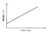
ここで、二次電池2をリチウムイオン電池で構成した場合、SOCと二次電池2の電圧(以降、電池電圧と称す)との間には図2に示すような比例関係があり、充放電制御部5aは、電池電圧を監視することによって二次電池2のSOCを検出している。そして、本実施形態の充放電制御部5aは、通常時に二次電池2のSOCが50(%)まで低下すれば、充電回路3によって二次電池2への充電を開始し、SOCが所定値(例えば60(%))まで達したら充電回路3を停止させる。または、強制放電回路4bによる放電電力を常に充電して補い、SOC50(%)を維持するようにしてもよい。 Here, when the
また図3に示すように、リチウムイオン電池で構成される二次電池2をSOC100(%)で保存した場合(特性Y1)と、SOC60(%)で保存した場合(特性Y2)とでは、SOC100(%)で保存した場合のほうが、容量劣化が速く進行する。すなわち、二次電池2の容量劣化は、残存容量が大きいほど劣化速度が速くなる。したがって、二次電池2の長寿命化のために、SOC100(%)まで充電を行うことなく、寿命保証のためにSOC50〜60(%)程度の低いSOCに抑えている。 In addition, as shown in FIG. 3, when the
そして本実施形態では、二次電池2をバックアップ電源として使用していない通常時(交流電源ACが通電状態)に、充放電コントローラ5が二次電池2の劣化状態を判定しており、通常時における電力供給装置の動作フローチャートを図4に示す。 In this embodiment, the charging / discharging
まず、充放電制御部5aは、電池電圧が、バックアップ保証のために設定されたバックアップ保証SOC(例えば、初期状態では50(%))に対応する電池電圧(以降、バックアップ保証電圧Vbと称す)以下であるか否かを判定する(S1)。電池電圧がバックアップ保証電圧Vb以下であれば、充電回路3によって二次電池2への充電を開始し(S2)、電池電圧が、寿命保証のために予め設定された充電終了SOC(例えば、60(%))に対応する電池電圧(以降、充電終了電圧Vsと称す)に達したか否かを判定し(S3)、電池電圧が充電終了電圧Vs未満であれば、充電動作を継続する。そして、ステップS2において電池電圧がバックアップ保証電圧Vbを上回っている場合、またはステップS3において電池電圧が充電終了電圧Vsに達している場合に、二次電池2の寿命判定時期であるか否かを判定する(S4)。二次電池2の寿命判定時期は、所定の周期毎(例えば、1回/月)に設定されており、寿命判定時期でなければステップS1に戻って上記処理を繰り返す。 First, the charge /
二次電池2の寿命判定時期であれば、充放電制御部5aは、充電回路3または放電回路4によって電池電圧を初期バックアップ保証電圧Vb0に一致させた後、充電回路3によって二次電池2への充電を開始し(S5)、電池電圧が、寿命判定のために予め設定された第2のSOC(例えば、100(%))に対応する電池電圧(以降、寿命判定電圧Vhと称す)に達したか否かを判定し(S6)、電池電圧が寿命判定電圧Vh未満であれば、充電動作を継続する。そして、計時部5bは、初期バックアップ保証電圧Vb0から寿命判定電圧Vhまでの充電に要した時間(充電時間)を計時しており、判定部5cは、ステップS6において電池電圧が寿命判定電圧Vhに達している場合、充電時間に基づいて二次電池2の劣化状態を判定する(S7)。ここで、初期バックアップ保証電圧Vb0とは、初期状態の二次電池2に対して設定されたバックアップ保証電圧(初期状態のバックアップ保証SOCに等しい第1のSOC(例えば、SOC50(%))に対応する電池電圧)である。 If it is time to determine the life of the
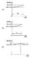
以下、充電時間を考慮して二次電池2の劣化状態を判定する判定処理について詳述する。まず図5(b)に示すように、第1のSOC50%に対応する電池電圧3.9(V)を初期バックアップ保証電圧Vb0とし、第2のSOC100%に対応する電池電圧4.2(V)を寿命判定電圧Vhとした場合、初期バックアップ保証電圧Vb0から寿命判定電圧Vhまでの充電時間(計測充電時間)をt1とする。 Hereinafter, the determination process for determining the deterioration state of the
そして、判定部5cは、初期状態の二次電池2の充電時間である初期充電時間t0(初期所要時間)を記憶しておき、初期充電時間t0に対する計測充電時間t1の比率[t1/t0]から二次電池2の劣化状態を判定する。この場合、
劣化状態=t1/t0 ………(1)
で表され、[t1/t0]が小さいほど、二次電池2が劣化していると判定される。この場合、後述の二次電池2の容量に基づいた判定処理に比べて、処理の簡略化を図ることができる。And the
Deterioration state = t1 / t0 (1)
It is determined that the
また、判定部5cは、充電時間を考慮して導出した二次電池2の容量に基づいて二次電池2の劣化状態を判定してもよい。まず図5(b)に示すように、第1のSOC50%に対応する電池電圧3.9(V)を初期バックアップ保証電圧Vb0とし、第2のSOC100%に対応する電池電圧4.2(V)を寿命判定電圧Vhとし、充電回路3が行う定電流充電の充電電力をP1(W)とし、SOCの充電分である充電SOCを50(%)[=100(%)−50(%)]とした場合、初期バックアップ保証電圧Vb0から寿命判定電圧Vhまでの充電時間(計測充電時間)がt1であったとする。このとき、SOC100(%)時における現状の二次電池2の容量C1(Wh)は、
C1(Wh)=t1(h)×P1(W)÷充電SOC(%)×100 ………(2)
となる(以降、計測容量C1と称す)。Further, the
C1 (Wh) = t1 (h) × P1 (W) ÷ charging SOC (%) × 100 (2)
(Hereinafter referred to as measurement capacity C1).
そして、判定部5cは、初期状態のSOC100(%)時における二次電池2の容量C0(Wh)を予め記憶しており(以降、初期容量C0と称す)、二次電池2の劣化状態は、
劣化状態=C1/C0 ………(3)
で表される。すなわち、[C1/C0]が小さいほど、二次電池2が劣化していると判定される。このように、充電時間に基づいて導出した二次電池2の容量C1を初期容量C0と比較することで、二次電池2の劣化状態を判定可能となる。The
Degraded state = C1 / C0 (3)
It is represented by That is, it is determined that the
なお、二次電池2の初期容量C0(Wh)は、初期状態の二次電池2を用いて初期充電時間t0を計時し(図5(a)参照)、
C0(Wh)=t0(h)×P1(W)÷充電SOC(%)×100 ………(4)
によって算出した結果を記憶してもよい。The initial capacity C0 (Wh) of the
C0 (Wh) = t0 (h) × P1 (W) ÷ Charging SOC (%) × 100 (4)
The result calculated by may be stored.
なお、寿命判定電圧Vhを、SOC100(%)ではなく、例えばSOC60(%)に対応する電池電圧に設定してもよいが、充電時間が短くなるために判定精度の点では、高いSOCまで充電したほうが有利となる。 The life determination voltage Vh may be set to a battery voltage corresponding to, for example, SOC 60 (%) instead of the SOC 100 (%). However, since the charging time is shortened, charging is performed up to a high SOC in terms of determination accuracy. This is more advantageous.
そして判定部5cは、上記式(1)または(3)で求められた二次電池2の劣化状態に基づいて、二次電池2の劣化状態が進行しているか否かを判定する(S8)。劣化状態が0.9に低下した場合は、計測容量C1が初期容量C0の90(%)にまで低下しており、SOC100(%)での容量は90(Wh)となる。而して、バックアップ用として必要な50(Wh)を確保するためには、バックアップ保証SOC56(%)が必要となる。 And the
そこで、充放電制御部5aは、バックアップ保証SOC56(%)に対応する4.0(V)をバックアップ保証電圧Vbに設定することで、二次電池2の劣化状態に応じてバックアップ保証電圧Vbを補正する(S9)。以降、充放電制御部5aは、この補正したバックアップ保証電圧Vb、および充電終了電圧Vsを用いて、上記ステップS1〜S3の通常時における充放電制御を行うので(図5(c)参照)、二次電池2の劣化状態に依らず、バックアップ用として必要な50(Wh)を確保できる。すなわち、充放電制御部5aは、判定部5cによって判定された二次電池2の劣化状態に応じて、通常時における二次電池2のSOCを設定している。 Therefore, the charge /
さらに、定期的に上記ステップS5〜S9のバックアップ保証電圧Vbの補正処理を行い、充電後のSOC100%時における二次電池2の計測容量C1(Wh)が55(Wh)にまで低下した場合には、図示しない表示灯やブザー等の報知手段でユーザに報知し、二次電池2の交換をユーザに促す。 Further, the backup guarantee voltage Vb is corrected periodically in steps S5 to S9, and the measured capacity C1 (Wh) of the
また、二次電池2の温度と電池容量との関係は、図6に示すように、電池温度が低いほど電池容量は低下する。したがって、温度補正を行わない場合、二次電池2の温度が低下すると、バックアップ用として必要な容量(Wh)を確保できなくなる虞がある。そこで、充放電制御部5aは、二次電池2の温度特性として、図7に示すように、二次電池の温度と、バックアップ用として必要な容量(Wh)を確保するためのバックアップ保証SOCとの関係を記憶している。なお、図7に示す二次電池2の温度特性は二次電池2の劣化状態に応じて変動し、例えば劣化状態が進行すると、バックアップ用として必要な容量(Wh)が増加する。そこで、本実施形態では、二次電池2の劣化状態毎に複数パターンの温度特性を記憶する構成や、温度特性パターンを二次電池2の劣化状態に応じて変動させる構成を備える。 As shown in FIG. 6, the relationship between the temperature of the
そして、サーミスタ7によって、二次電池2の温度と相関関係にある二次電池2周辺の環境温度を測定し、充放電制御部5aは、サーミスタ7が測定した環境温度を図7に示す温度特性に照合することで、現在の環境温度において必要なバックアップ保証SOCを算出し、当該算出したバックアップ保証SOCに基づいてバックアップ保証電圧Vbを補正することで、二次電池2の温度に依らず、バックアップ用として必要な容量(Wh)を確保することが可能となる。すなわち、充放電制御部5aは、二次電池2の温度に応じて、通常時における二次電池2のバックアップ保証SOCを設定している。また、環境温度は常に変化するため、図8に示すように所定の温度範囲毎に必要なSOCを規定すれば、充放電制御部5aによるバックアップ保証電圧Vbの温度補正を簡略化できる。 Then, the ambient temperature around the
(実施形態2)
本実施形態の電力供給装置の構成は実施形態1と同様であり、同様の構成には同一の符号を付して説明は省略する。(Embodiment 2)
The configuration of the power supply apparatus of the present embodiment is the same as that of the first embodiment, and the same components are denoted by the same reference numerals and description thereof is omitted.
本実施形態では、二次電池2をバックアップ電源として使用していない通常時(交流電源ACが通電状態)に、充放電コントローラ5が、放電時間を考慮して二次電池2の劣化状態を判定しており、通常時における電力供給装置の動作フローチャートを図9に示す。 In the present embodiment, during normal times when the
まず、充放電制御部5aは実施形態1と同様に、バックアップ保証電圧Vb、および充電終了電圧Vsを用いて、上記ステップS1〜S3の通常時における充放電制御を行い、ステップS4において、例えば1回/月の寿命判定時期でなければステップS1に戻って上記処理を繰り返す。 First, similarly to the first embodiment, the charge /
二次電池2の寿命判定時期であれば、充放電制御部5aは、充電回路3によって電池電圧を寿命判定電圧Vhに一致させた後、放電回路4の強制放電回路4aによって二次電池2の放電を開始し(S15)、電池電圧が初期バックアップ保証電圧Vb0にまで低下したか否かを判定し(S16)、電池電圧が初期バックアップ保証電圧Vb0を上回っていれば、放電動作を継続する。そして、計時部5bは、寿命判定電圧Vhから初期バックアップ保証電圧Vb0までの放電に要した時間(放電時間)を計時しており、判定部5cは、ステップS16において電池電圧が初期バックアップ保証電圧Vb0にまで低下している場合、放電時間に基づいて二次電池2の劣化状態を判定する(S17)。 If it is the life determination time of the
以下、二次電池2の劣化状態の判定処理について詳述する。 Hereinafter, the determination process of the deterioration state of the
まず図10(b)に示すように、第1のSOC50%に対応する電池電圧3.9(V)を初期バックアップ保証電圧Vb0とし、第2のSOC100%に対応する電池電圧4.2(V)を寿命判定電圧Vhとした場合、寿命判定電圧Vhから初期バックアップ保証電圧Vb0までの放電時間(計測放電時間)がt11であったとする。 First, as shown in FIG. 10B, the battery voltage 3.9 (V) corresponding to the first SOC 50% is set as the initial backup guarantee voltage Vb0, and the battery voltage 4.2 (V) corresponding to the
そして、判定部5cは、初期状態の二次電池2の放電時間である初期放電時間t10(初期所要時間)を記憶しておき、初期放電時間t10に対する計測放電時間t11の比率[t11/t10]から二次電池2の劣化状態を判定する。この場合、
劣化状態=t11/t10 ………(5)
で表され、[t11/t10]が小さいほど、二次電池2が劣化していると判定される。この場合、後述の二次電池2の容量に基づいた判定処理に比べて、処理の簡略化を図ることができる。Then, the
Deterioration state = t11 / t10 (5)
It is determined that the
また、判定部5cは、放電時間を考慮して導出した二次電池2の容量に基づいて二次電池2の劣化状態を判定してもよい。まず図10(b)に示すように、第1のSOC50%に対応する電池電圧3.9(V)を初期バックアップ保証電圧Vb0とし、第2のSOC100%に対応する電池電圧4.2(V)を寿命判定電圧Vhとし、強制放電回路4bが行う強制放電の放電電力をP11(W)とし、SOCの放電分である放電SOCを50(%)[=100(%)−50(%)]とした場合、寿命判定電圧Vhから初期バックアップ保証電圧Vb0までの放電時間(計測放電時間)がt11であったとする。このとき、SOC100(%)時における現状の二次電池2の容量C11(Wh)は、
C11(Wh)=t11(h)×P11(W)÷放電SOC(%)×100 …(6)
となる(以降、計測容量C11と称す)。Further, the
C11 (Wh) = t11 (h) × P11 (W) ÷ discharge SOC (%) × 100 (6)
(Hereinafter referred to as measurement capacity C11).
そして、判定部5cは、初期状態のSOC100(%)時における二次電池2の容量C10(Wh)を予め記憶しており(以降、初期容量C10と称す)、二次電池2の劣化状態は、
劣化状態=C11/C10 ………(7)
で表される。すなわち、[C11/C10]が小さいほど、二次電池2が劣化していると判定される。このように、放電時間に基づいて導出した二次電池2の容量C11を初期容量C10と比較することで、二次電池2の劣化状態を判定可能となる。なお、二次電池2の初期容量C10(Wh)は、初期状態の二次電池2を用いて初期放電時間t10を計時し(図10(a)参照)、
C10(Wh)=t10(h)×P11(W)÷放電SOC(%)×100 …(8)
によって算出した結果を記憶してもよい。And the
Deterioration state = C11 / C10 (7)
It is represented by That is, it is determined that the
C10 (Wh) = t10 (h) × P11 (W) ÷ discharge SOC (%) × 100 (8)
The result calculated by may be stored.
なお、寿命判定電圧Vhを、SOC100(%)ではなく、例えばSOC60(%)に対応する電池電圧に設定してもよいが、放電時間が短くなるために判定精度の点では、高いSOCから放電したほうが有利となる。 The life determination voltage Vh may be set to a battery voltage corresponding to, for example, SOC 60 (%) instead of the SOC 100 (%). However, since the discharge time is shortened, the discharge from a high SOC is performed in terms of determination accuracy. This is more advantageous.
そして、判定部5cは、上記式(5)または(7)で求められた二次電池2の劣化状態に基づいて、二次電池2の劣化状態が進行しているか否かを判定する(S18)。劣化状態が0.9に低下した場合は、計測容量C1が初期容量C0の90(%)にまで低下しており、SOC100(%)での容量は90(Wh)となる。而して、バックアップ用として必要な50(Wh)を確保するためには、バックアップ保証SOC56(%)が必要となる。 And the
そこで、充放電制御部5aは、バックアップ保証SOC56(%)に対応する4.0(V)をバックアップ保証電圧Vbに設定することで、二次電池2の劣化状態に応じてバックアップ保証電圧Vbを補正する(S19)。以降、充放電制御部5aは、この補正したバックアップ保証電圧Vb、および充電終了電圧Vsを用いて、上記ステップS1〜S3の通常時における充放電制御を行うので(図10(c)参照)、二次電池2の劣化状態に依らず、バックアップ用として必要な50(Wh)を確保できる。すなわち、充放電制御部5aは、判定部5cによって判定された二次電池2の劣化状態に応じて、通常時における二次電池2のバックアップ保証SOCを設定している。 Therefore, the charge /
さらに、定期的に上記ステップS15〜S19のバックアップ保証電圧Vbの補正処理を行い、SOC100%時における現状の二次電池2の計測容量C11(Wh)が55(Wh)にまで低下した場合には、図示しない表示灯やブザー等の報知手段でユーザに報知し、二次電池2の交換をユーザに促す。 Furthermore, when the backup guarantee voltage Vb is corrected periodically in steps S15 to S19, and the current measurement capacity C11 (Wh) of the
また、充放電制御部5aは実施形態1と同様に、サーミスタ7が測定した環境温度に基づいて、バックアップ保証電圧Vbの温度補正を行う。 Similarly to the first embodiment, the charge /
なお、本実施形態では、放電回路4の強制放電回路4bをステップS15の放電に用いることで、構成の簡略化を図っているが、放電回路4とは別構成の放電手段を設けてもよく、さらには負荷機器Lの消費電力を放電に利用してもよい。 In the present embodiment, the configuration is simplified by using the forced
1 コンバータ回路
2 二次電池
3 充電回路
4 放電回路
5 充放電コントローラ
5a 充放電制御部
5b 計時部
5c 判定部
6 停電監視回路
7 サーミスタDESCRIPTION OF
Claims (5)
Translated fromJapanese二次電池を充電する充電手段と、
二次電池を放電させる放電手段と、
充電手段による二次電池の充電および放電手段による二次電池の放電を制御して、通常時の所定タイミングで二次電池を第1のSOCから第2のSOCまで充電させる、または通常時の所定タイミングで二次電池を第2のSOCから第1のSOCまで放電させる充放電制御手段と、
充放電制御手段が二次電池を第1のSOCから第2のSOCまで充電させたとき、または充放電制御手段が二次電池を第2のSOCから第1のSOCまで放電させたときの所要時間を計測する計時手段と、
計時手段の計測結果に基づいて二次電池の劣化状態を判定する判定手段とを備え、
二次電池は、通常時に所定の容量以上に充電されて非常時に負荷機器へ電力を供給するバックアップ電源として用いられ、
充放電制御手段は、通常時における二次電池をバックアップ保証SOC以上に充電し、判定手段によって判定された二次電池の劣化状態に応じて、通常時における二次電池が所定の容量以上となるようにバックアップ保証SOCを変動させる
ことを特徴とする電力供給装置。A secondary battery,
A charging means for charging the secondary battery;
Discharging means for discharging the secondary battery;
The charging of the secondary battery by the charging means and the discharging of the secondary battery by the discharging means are controlled so that the secondary battery is charged from the first SOC to the second SOC at a predetermined timing at normal time, or predetermined at normal time Charge / discharge control means for discharging the secondary battery from the second SOC to the first SOC at a timing;
Required when the charge / discharge control means charges the secondary battery from the first SOC to the second SOC, or when the charge / discharge control means discharges the secondary battery from the second SOC to the first SOC A time measuring means for measuring time;
Determination means for determining the deterioration state of the secondary battery based on the measurement result of the time measuring means,
The secondary battery is used as a backup power source that is charged to a predetermined capacity or more during normal operation and supplies power to load equipment in an emergency.
The charge / discharge control means charges the secondary battery at the normal time to a backup guaranteed SOC or more, and the secondary battery at the normal time becomes a predetermined capacity or more according to the deterioration state of the secondary battery determined by the determination means. As described above, the power supply apparatus is characterizedby changing the backup guarantee SOC .
Priority Applications (5)
| Application Number | Priority Date | Filing Date | Title |
|---|---|---|---|
| JP2009244963AJP5789736B2 (en) | 2009-10-23 | 2009-10-23 | Power supply |
| PCT/IB2010/002681WO2011048471A1 (en) | 2009-10-23 | 2010-10-20 | Power supply apparatus |
| CN201080047099.0ACN102612656B (en) | 2009-10-23 | 2010-10-20 | Power supply device |
| US13/503,434US9086463B2 (en) | 2009-10-23 | 2010-10-20 | Power supply apparatus |
| EP10824534.1AEP2492702B1 (en) | 2009-10-23 | 2010-10-20 | Power supply apparatus |
Applications Claiming Priority (1)
| Application Number | Priority Date | Filing Date | Title |
|---|---|---|---|
| JP2009244963AJP5789736B2 (en) | 2009-10-23 | 2009-10-23 | Power supply |
Publications (2)
| Publication Number | Publication Date |
|---|---|
| JP2011089938A JP2011089938A (en) | 2011-05-06 |
| JP5789736B2true JP5789736B2 (en) | 2015-10-07 |
Family
ID=43899869
Family Applications (1)
| Application Number | Title | Priority Date | Filing Date |
|---|---|---|---|
| JP2009244963AActiveJP5789736B2 (en) | 2009-10-23 | 2009-10-23 | Power supply |
Country Status (5)
| Country | Link |
|---|---|
| US (1) | US9086463B2 (en) |
| EP (1) | EP2492702B1 (en) |
| JP (1) | JP5789736B2 (en) |
| CN (1) | CN102612656B (en) |
| WO (1) | WO2011048471A1 (en) |
Families Citing this family (32)
| Publication number | Priority date | Publication date | Assignee | Title |
|---|---|---|---|---|
| JP5143273B1 (en)* | 2011-11-30 | 2013-02-13 | 株式会社東芝 | Battery management device and battery management method |
| CN103135063A (en)* | 2012-12-21 | 2013-06-05 | 郝勇 | Detection and monitoring method of lead-acid storage battery |
| BR112015017892B1 (en)* | 2013-02-01 | 2022-01-11 | Toyota Jidosha Kabushiki Kaisha | BATTERY SYSTEM |
| US10591968B2 (en) | 2013-09-30 | 2020-03-17 | Hewlett Packard Enterprise Development Lp | Selectively-enabling battery back-up power based on a power demand |
| JP2015155859A (en)* | 2014-02-21 | 2015-08-27 | ソニー株式会社 | Battery residual amount estimation device, battery pack, power storage device, electric vehicle and battery residual amount estimation method |
| JP5742999B2 (en)* | 2014-04-08 | 2015-07-01 | 三菱自動車工業株式会社 | Charging time estimation device and charging time estimation method |
| US20150377971A1 (en)* | 2014-06-27 | 2015-12-31 | Icc-Nexergy, Inc. | Required Available Capacity Indication for Battery Backup Unit |
| EP3010112A1 (en)* | 2014-10-14 | 2016-04-20 | Pace Plc | Method and system for charging a battery |
| JP6054934B2 (en)* | 2014-11-17 | 2016-12-27 | レノボ・シンガポール・プライベート・リミテッド | BACKUP SYSTEM, MANAGEMENT METHOD, AND INFORMATION PROCESSING DEVICE FOR EXTENDING LIFE TIME OF SECONDARY BATTERY |
| US10008879B2 (en)* | 2014-12-11 | 2018-06-26 | Fisher Controls International Llc | Self-discharging reserve power units and related methods |
| US20160202749A1 (en)* | 2015-01-13 | 2016-07-14 | Netlist, Inc. | System and method for determining charge of a secondary power supply for a memory system |
| US10403936B2 (en)* | 2015-01-15 | 2019-09-03 | Nec Corporation | Storage cell control system, storage cell control method, and recording medium |
| JP5862815B1 (en)* | 2015-03-06 | 2016-02-16 | 日本電気株式会社 | Battery life detection device, power storage device, battery life detection method and program |
| US10386421B2 (en)* | 2015-09-14 | 2019-08-20 | Facebook, Inc. | Energy based battery backup unit testing |
| WO2017170205A1 (en)* | 2016-03-28 | 2017-10-05 | Ntn株式会社 | Secondary battery degradation assessment device |
| JP2017181484A (en)* | 2016-03-28 | 2017-10-05 | Ntn株式会社 | Secondary battery deterioration determination device |
| JP2018002435A (en)* | 2016-07-06 | 2018-01-11 | 株式会社日立製作所 | Elevator equipment |
| CN106646262A (en)* | 2017-01-03 | 2017-05-10 | 重庆长安汽车股份有限公司 | Power battery capacity estimation method, power battery capacity estimation system, and electric vehicle |
| JP6981015B2 (en)* | 2017-02-27 | 2021-12-15 | 日本電気株式会社 | Power supply system, control device, control method and program |
| WO2019130774A1 (en)* | 2017-12-26 | 2019-07-04 | パナソニックIpマネジメント株式会社 | Battery management device, battery system, and vehicle power supply system |
| US10868431B2 (en)* | 2018-01-16 | 2020-12-15 | Cisco Technology, Inc. | Battery charging cut-off circuit |
| KR102442632B1 (en)* | 2018-02-09 | 2022-09-08 | 주식회사 엘지에너지솔루션 | Apparatus and method for estimating state of secondary battery |
| CN108549031A (en)* | 2018-03-26 | 2018-09-18 | 奇瑞汽车股份有限公司 | Power battery circulation endurance test rack |
| JP7378921B2 (en)* | 2018-10-19 | 2023-11-14 | 三菱重工業株式会社 | Secondary battery management system, secondary battery management method, secondary battery management program, secondary battery system |
| JP7149836B2 (en)* | 2018-12-21 | 2022-10-07 | 株式会社日立製作所 | Power supply system, diagnostic equipment and uninterruptible power supply |
| DE102020201836A1 (en)* | 2020-02-14 | 2021-08-19 | Robert Bosch Gesellschaft mit beschränkter Haftung | Method for determining the state of aging of at least one electrical energy storage unit |
| US20220200295A1 (en)* | 2020-12-23 | 2022-06-23 | Medtronic, Inc. | Systems and method for charging batteries |
| JP7691241B2 (en)* | 2021-01-22 | 2025-06-11 | 東日本旅客鉄道株式会社 | Method for controlling charging and discharging of storage battery in power supply system |
| ES3001184T3 (en)* | 2021-02-09 | 2025-03-04 | Contemporary Amperex Technology Hong Kong Ltd | Battery charging method, controller, battery management system, battery and electrical appliance |
| US12429526B2 (en)* | 2021-07-23 | 2025-09-30 | Phoenix Broadband Technologies, Llc | Method and apparatus for estimating the available runtime of a battery backup system |
| WO2023035161A1 (en)* | 2021-09-08 | 2023-03-16 | 宁德时代新能源科技股份有限公司 | Power battery charging method and battery management system |
| EP4207537A1 (en)* | 2021-12-29 | 2023-07-05 | Polarium Energy Solutions AB | Method and battery module with state of health determination |
Family Cites Families (21)
| Publication number | Priority date | Publication date | Assignee | Title |
|---|---|---|---|---|
| US5018148A (en)* | 1989-03-01 | 1991-05-21 | Ncr Corporation | Method and apparatus for power failure protection |
| JP2727149B2 (en) | 1992-09-14 | 1998-03-11 | エムアンドシー 株式会社 | Battery inspection method |
| US5606242A (en)* | 1994-10-04 | 1997-02-25 | Duracell, Inc. | Smart battery algorithm for reporting battery parameters to an external device |
| JP3322116B2 (en) | 1996-02-28 | 2002-09-09 | 新神戸電機株式会社 | Storage battery deterioration state tester for AC uninterruptible power supply |
| DE69826929T2 (en)* | 1997-06-24 | 2005-03-10 | Matsushita Electric Industrial Co., Ltd., Kadoma | Method for detecting the operating state of rechargeable batteries with non-aqueous electrolyte |
| JP3659772B2 (en)* | 1997-08-07 | 2005-06-15 | 三菱自動車工業株式会社 | Battery deterioration judgment device |
| DE69830888T2 (en)* | 1997-12-03 | 2006-03-30 | Matsushita Electric Industrial Co., Ltd., Kadoma | Method for the temperature-dependent charging of an auxiliary power source which is subject to a self-discharge |
| TW200417706A (en)* | 2003-03-13 | 2004-09-16 | Wetek Corp | The method and apparatus for auto charging-discharging and monitoring of the urgent lighting |
| JP4649101B2 (en)* | 2003-09-10 | 2011-03-09 | 株式会社日本自動車部品総合研究所 | Secondary battery status detection device and status detection method |
| JP4134877B2 (en) | 2003-10-20 | 2008-08-20 | トヨタ自動車株式会社 | Storage device control device |
| EP1632781A1 (en)* | 2004-09-02 | 2006-03-08 | Delphi Technologies, Inc. | Method and apparatus for battery capacity detection |
| JP2006177764A (en)* | 2004-12-22 | 2006-07-06 | Sanyo Electric Co Ltd | Learning capacity correcting method of battery |
| JP5460943B2 (en) | 2005-08-19 | 2014-04-02 | 株式会社Nttファシリティーズ | Degradation judgment device, degradation judgment method, computer program |
| CN100535680C (en) | 2005-08-19 | 2009-09-02 | 株式会社Ntt设施 | Deterioration judging device and method, computer program |
| US20070080692A1 (en)* | 2005-09-12 | 2007-04-12 | Evans Glen F | Method and apparatus for performing automated power plant battery backup capacity measurement |
| JP2007166789A (en)* | 2005-12-14 | 2007-06-28 | Toyota Motor Corp | Method and apparatus for estimating the full charge capacity of a secondary battery |
| CN100541396C (en)* | 2006-01-16 | 2009-09-16 | 宏碁股份有限公司 | Method for prolonging battery life of portable computer |
| US7800344B2 (en)* | 2007-02-20 | 2010-09-21 | Delphi Technologies, Inc. | Method of determining the energy capacity of a battery |
| US8558508B2 (en)* | 2007-06-08 | 2013-10-15 | C & C Power, Inc. | Battery system and management method |
| JP2009012345A (en) | 2007-07-05 | 2009-01-22 | Seiko Epson Corp | Liquid ejection device |
| JP4494453B2 (en)* | 2007-11-13 | 2010-06-30 | トヨタ自動車株式会社 | Secondary battery control device and control method |
- 2009
- 2009-10-23JPJP2009244963Apatent/JP5789736B2/enactiveActive
- 2010
- 2010-10-20CNCN201080047099.0Apatent/CN102612656B/ennot_activeExpired - Fee Related
- 2010-10-20USUS13/503,434patent/US9086463B2/ennot_activeExpired - Fee Related
- 2010-10-20EPEP10824534.1Apatent/EP2492702B1/enactiveActive
- 2010-10-20WOPCT/IB2010/002681patent/WO2011048471A1/enactiveApplication Filing
Also Published As
| Publication number | Publication date |
|---|---|
| CN102612656B (en) | 2015-07-29 |
| CN102612656A (en) | 2012-07-25 |
| EP2492702A4 (en) | 2017-05-03 |
| JP2011089938A (en) | 2011-05-06 |
| EP2492702A1 (en) | 2012-08-29 |
| US9086463B2 (en) | 2015-07-21 |
| US20120248876A1 (en) | 2012-10-04 |
| WO2011048471A1 (en) | 2011-04-28 |
| EP2492702B1 (en) | 2020-07-15 |
Similar Documents
| Publication | Publication Date | Title |
|---|---|---|
| JP5789736B2 (en) | Power supply | |
| US7560901B2 (en) | Internal short detection apparatus for secondary-battery, internal short detection method for secondary-battery, battery-pack, and electronic equipment | |
| US8996324B2 (en) | Battery-state monitoring apparatus | |
| JP5815195B2 (en) | Battery state detection device and battery pack incorporating the same | |
| JP4817647B2 (en) | Secondary battery life judgment method. | |
| US8427003B2 (en) | Electric power supply device | |
| WO2010004985A1 (en) | Battery state detection device | |
| JP2011053088A (en) | Method for computing residual capacity of secondary battery and secondary battery device | |
| KR20060086024A (en) | Battery pack monitoring device and method | |
| JP2012253975A (en) | Charging/discharging control method for alkali storage battery, and charging/discharging system | |
| JP2010139396A (en) | Battery lifetime detector, energy storage device, and method of detecting battery lifetime | |
| JPH11329512A (en) | Secondary battery capacity deterioration judging method and its judging device | |
| JP2009178040A (en) | Battery group controller and battery power supply system | |
| JP5390981B2 (en) | Power backup device | |
| JP2010166752A (en) | Battery pack and method of controlling charging and discharging | |
| JP2009064682A (en) | Battery deterioration judging device, and lithium ion battery pack equipped with the same | |
| JP2004226393A (en) | Battery level measurement device | |
| JP2020008520A (en) | Method for determining life of power storage system and power storage system | |
| JP2009112180A (en) | Battery pack and control method thereof | |
| JP2011038878A (en) | Deterioration degree determination method for secondary battery and secondary battery | |
| JP5620423B2 (en) | Electronic device and battery charging method for electronic device | |
| JP2010230371A (en) | System and method for testing secondary battery capacity | |
| JPH1118314A (en) | Method and equipment for charging lithium ion secondary battery | |
| JP7658789B2 (en) | Battery capacity management system, battery capacity management method, and battery capacity management program | |
| JP2007282461A (en) | Capacitor power accumulating device and control method therefor |
Legal Events
| Date | Code | Title | Description |
|---|---|---|---|
| A711 | Notification of change in applicant | Free format text:JAPANESE INTERMEDIATE CODE: A712 Effective date:20120118 | |
| A621 | Written request for application examination | Free format text:JAPANESE INTERMEDIATE CODE: A621 Effective date:20120608 | |
| A131 | Notification of reasons for refusal | Free format text:JAPANESE INTERMEDIATE CODE: A131 Effective date:20140204 | |
| A521 | Written amendment | Free format text:JAPANESE INTERMEDIATE CODE: A523 Effective date:20140407 | |
| A711 | Notification of change in applicant | Free format text:JAPANESE INTERMEDIATE CODE: A711 Effective date:20141007 | |
| TRDD | Decision of grant or rejection written | ||
| A01 | Written decision to grant a patent or to grant a registration (utility model) | Free format text:JAPANESE INTERMEDIATE CODE: A01 Effective date:20141224 | |
| A61 | First payment of annual fees (during grant procedure) | Free format text:JAPANESE INTERMEDIATE CODE: A61 Effective date:20150116 | |
| R151 | Written notification of patent or utility model registration | Ref document number:5789736 Country of ref document:JP Free format text:JAPANESE INTERMEDIATE CODE: R151 |