JP5785957B2 - Electrosurgical instruments and systems - Google Patents
Electrosurgical instruments and systemsDownload PDFInfo
- Publication number
- JP5785957B2 JP5785957B2JP2012550508AJP2012550508AJP5785957B2JP 5785957 B2JP5785957 B2JP 5785957B2JP 2012550508 AJP2012550508 AJP 2012550508AJP 2012550508 AJP2012550508 AJP 2012550508AJP 5785957 B2JP5785957 B2JP 5785957B2
- Authority
- JP
- Japan
- Prior art keywords
- electrode
- electrosurgical
- return
- output connection
- coagulation
- Prior art date
- Legal status (The legal status is an assumption and is not a legal conclusion. Google has not performed a legal analysis and makes no representation as to the accuracy of the status listed.)
- Active
Links
Images


Classifications
- A—HUMAN NECESSITIES
- A61—MEDICAL OR VETERINARY SCIENCE; HYGIENE
- A61B—DIAGNOSIS; SURGERY; IDENTIFICATION
- A61B18/00—Surgical instruments, devices or methods for transferring non-mechanical forms of energy to or from the body
- A61B18/04—Surgical instruments, devices or methods for transferring non-mechanical forms of energy to or from the body by heating
- A61B18/12—Surgical instruments, devices or methods for transferring non-mechanical forms of energy to or from the body by heating by passing a current through the tissue to be heated, e.g. high-frequency current
- A61B18/14—Probes or electrodes therefor
- A61B18/1402—Probes for open surgery
- A—HUMAN NECESSITIES
- A61—MEDICAL OR VETERINARY SCIENCE; HYGIENE
- A61B—DIAGNOSIS; SURGERY; IDENTIFICATION
- A61B18/00—Surgical instruments, devices or methods for transferring non-mechanical forms of energy to or from the body
- A61B18/04—Surgical instruments, devices or methods for transferring non-mechanical forms of energy to or from the body by heating
- A61B18/12—Surgical instruments, devices or methods for transferring non-mechanical forms of energy to or from the body by heating by passing a current through the tissue to be heated, e.g. high-frequency current
- A61B18/14—Probes or electrodes therefor
- A61B18/148—Probes or electrodes therefor having a short, rigid shaft for accessing the inner body transcutaneously, e.g. for neurosurgery or arthroscopy
- A—HUMAN NECESSITIES
- A61—MEDICAL OR VETERINARY SCIENCE; HYGIENE
- A61B—DIAGNOSIS; SURGERY; IDENTIFICATION
- A61B18/00—Surgical instruments, devices or methods for transferring non-mechanical forms of energy to or from the body
- A61B18/04—Surgical instruments, devices or methods for transferring non-mechanical forms of energy to or from the body by heating
- A61B18/12—Surgical instruments, devices or methods for transferring non-mechanical forms of energy to or from the body by heating by passing a current through the tissue to be heated, e.g. high-frequency current
- A61B18/14—Probes or electrodes therefor
- A61B18/16—Indifferent or passive electrodes for grounding
- A—HUMAN NECESSITIES
- A61—MEDICAL OR VETERINARY SCIENCE; HYGIENE
- A61B—DIAGNOSIS; SURGERY; IDENTIFICATION
- A61B18/00—Surgical instruments, devices or methods for transferring non-mechanical forms of energy to or from the body
- A61B2018/00005—Cooling or heating of the probe or tissue immediately surrounding the probe
- A61B2018/00011—Cooling or heating of the probe or tissue immediately surrounding the probe with fluids
- A61B2018/00029—Cooling or heating of the probe or tissue immediately surrounding the probe with fluids open
- A61B2018/00035—Cooling or heating of the probe or tissue immediately surrounding the probe with fluids open with return means
- A—HUMAN NECESSITIES
- A61—MEDICAL OR VETERINARY SCIENCE; HYGIENE
- A61B—DIAGNOSIS; SURGERY; IDENTIFICATION
- A61B18/00—Surgical instruments, devices or methods for transferring non-mechanical forms of energy to or from the body
- A61B2018/00053—Mechanical features of the instrument of device
- A61B2018/0016—Energy applicators arranged in a two- or three dimensional array
- A—HUMAN NECESSITIES
- A61—MEDICAL OR VETERINARY SCIENCE; HYGIENE
- A61B—DIAGNOSIS; SURGERY; IDENTIFICATION
- A61B18/00—Surgical instruments, devices or methods for transferring non-mechanical forms of energy to or from the body
- A61B2018/00053—Mechanical features of the instrument of device
- A61B2018/00172—Connectors and adapters therefor
- A61B2018/00178—Electrical connectors
- A—HUMAN NECESSITIES
- A61—MEDICAL OR VETERINARY SCIENCE; HYGIENE
- A61B—DIAGNOSIS; SURGERY; IDENTIFICATION
- A61B18/00—Surgical instruments, devices or methods for transferring non-mechanical forms of energy to or from the body
- A61B2018/00571—Surgical instruments, devices or methods for transferring non-mechanical forms of energy to or from the body for achieving a particular surgical effect
- A61B2018/00589—Coagulation
- A—HUMAN NECESSITIES
- A61—MEDICAL OR VETERINARY SCIENCE; HYGIENE
- A61B—DIAGNOSIS; SURGERY; IDENTIFICATION
- A61B18/00—Surgical instruments, devices or methods for transferring non-mechanical forms of energy to or from the body
- A61B2018/00571—Surgical instruments, devices or methods for transferring non-mechanical forms of energy to or from the body for achieving a particular surgical effect
- A61B2018/00601—Cutting
- A—HUMAN NECESSITIES
- A61—MEDICAL OR VETERINARY SCIENCE; HYGIENE
- A61B—DIAGNOSIS; SURGERY; IDENTIFICATION
- A61B18/00—Surgical instruments, devices or methods for transferring non-mechanical forms of energy to or from the body
- A61B2018/00571—Surgical instruments, devices or methods for transferring non-mechanical forms of energy to or from the body for achieving a particular surgical effect
- A61B2018/00607—Coagulation and cutting with the same instrument
- A—HUMAN NECESSITIES
- A61—MEDICAL OR VETERINARY SCIENCE; HYGIENE
- A61B—DIAGNOSIS; SURGERY; IDENTIFICATION
- A61B18/00—Surgical instruments, devices or methods for transferring non-mechanical forms of energy to or from the body
- A61B18/04—Surgical instruments, devices or methods for transferring non-mechanical forms of energy to or from the body by heating
- A61B18/12—Surgical instruments, devices or methods for transferring non-mechanical forms of energy to or from the body by heating by passing a current through the tissue to be heated, e.g. high-frequency current
- A61B18/1206—Generators therefor
- A61B2018/124—Generators therefor switching the output to different electrodes, e.g. sequentially
- A—HUMAN NECESSITIES
- A61—MEDICAL OR VETERINARY SCIENCE; HYGIENE
- A61B—DIAGNOSIS; SURGERY; IDENTIFICATION
- A61B18/00—Surgical instruments, devices or methods for transferring non-mechanical forms of energy to or from the body
- A61B18/04—Surgical instruments, devices or methods for transferring non-mechanical forms of energy to or from the body by heating
- A61B18/12—Surgical instruments, devices or methods for transferring non-mechanical forms of energy to or from the body by heating by passing a current through the tissue to be heated, e.g. high-frequency current
- A61B18/14—Probes or electrodes therefor
- A61B2018/1472—Probes or electrodes therefor for use with liquid electrolyte, e.g. virtual electrodes
- A—HUMAN NECESSITIES
- A61—MEDICAL OR VETERINARY SCIENCE; HYGIENE
- A61B—DIAGNOSIS; SURGERY; IDENTIFICATION
- A61B18/00—Surgical instruments, devices or methods for transferring non-mechanical forms of energy to or from the body
- A61B18/04—Surgical instruments, devices or methods for transferring non-mechanical forms of energy to or from the body by heating
- A61B18/12—Surgical instruments, devices or methods for transferring non-mechanical forms of energy to or from the body by heating by passing a current through the tissue to be heated, e.g. high-frequency current
- A61B18/14—Probes or electrodes therefor
- A61B18/16—Indifferent or passive electrodes for grounding
- A61B2018/162—Indifferent or passive electrodes for grounding located on the probe body
- A—HUMAN NECESSITIES
- A61—MEDICAL OR VETERINARY SCIENCE; HYGIENE
- A61B—DIAGNOSIS; SURGERY; IDENTIFICATION
- A61B18/00—Surgical instruments, devices or methods for transferring non-mechanical forms of energy to or from the body
- A61B18/04—Surgical instruments, devices or methods for transferring non-mechanical forms of energy to or from the body by heating
- A61B18/12—Surgical instruments, devices or methods for transferring non-mechanical forms of energy to or from the body by heating by passing a current through the tissue to be heated, e.g. high-frequency current
- A61B18/14—Probes or electrodes therefor
- A61B18/16—Indifferent or passive electrodes for grounding
- A61B2018/165—Multiple indifferent electrodes
Landscapes
- Health & Medical Sciences (AREA)
- Surgery (AREA)
- Engineering & Computer Science (AREA)
- Life Sciences & Earth Sciences (AREA)
- Biomedical Technology (AREA)
- Otolaryngology (AREA)
- Nuclear Medicine, Radiotherapy & Molecular Imaging (AREA)
- Plasma & Fusion (AREA)
- Physics & Mathematics (AREA)
- Heart & Thoracic Surgery (AREA)
- Medical Informatics (AREA)
- Molecular Biology (AREA)
- Animal Behavior & Ethology (AREA)
- General Health & Medical Sciences (AREA)
- Public Health (AREA)
- Veterinary Medicine (AREA)
- Surgical Instruments (AREA)
Description
Translated fromJapanese本発明は、ジェネレータと、該ジェネレータから高周波(RF)電力を受け取るための電気外科用電極を含む電気外科用器具とを備える電気外科用システムに関する。かかるシステムは、一般的には外科的治療で、最も一般には、「鍵穴」手術または低侵襲手術において組織を切開および/または凝固させるために使用されるが、「観血的」手術でも使用される。 The present invention relates to an electrosurgical system comprising a generator and an electrosurgical instrument including an electrosurgical electrode for receiving radio frequency (RF) power from the generator. Such systems are typically used for surgical treatment, most commonly used to dissect and / or coagulate tissue in “keyhole” or minimally invasive surgery, but also in “open” surgery. The
有用な切開器具のための基準は、有用な凝固器具に必要な基準とは異なる。米国特許第6004319号明細書は、切開または凝固モードのいずれか一方で有効に動作することができるように設計された一対の電極を用いてこの問題に対処しようと試みている。 The criteria for a useful cutting instrument are different from those required for a useful coagulation instrument. U.S. Pat. No. 6,0043,319 attempts to address this problem with a pair of electrodes designed to be able to operate effectively in either an incision or coagulation mode.
本発明は、上記の問題に対する別の解決手段を提供し、一態様によれば、電気外科用器具と電気外科用ジェネレータとを含み、電気外科用器具は、それらの間の絶縁部材によって互いに間隔を空けて配置された少なくとも第1、第2および第3の電極を含み、第1の電極が、アクティブ電極を構成するように適合された特性を有し、第2の電極が、第1のリターン電極を構成するように適合された特性を有し、第3の電極が、第2のリターン電極を構成するように適合された特性を有し、電気外科用ジェネレータが、凝固用のRF波形または切開用のRF波形を生成可能な高周波エネルギの供給源と、電気外科用器具の第1、第2および第3の電極にそれぞれ接続された第1、第2および第3の出力接続部とを含み、ジェネレータは、切換え手段と制御装置とをさらに含み、制御装置は、切開用のRF波形が選択されたとき、切換え手段が、第1の出力接続部と第2の出力接続部との間に、したがって、第1の電極と第2の電極との間に切開用のRF波形を送り、凝固用のRF波形が選択されたとき、切換え手段が、第1の出力接続部と第3の出力接続部との間に、したがって、第1の電極と第3の電極との間に凝固用のRF波形を送るようになっている電気外科用システムを構成している。 The present invention provides another solution to the above problem and, according to one aspect, includes an electrosurgical instrument and an electrosurgical generator, the electrosurgical instrument being spaced from each other by an insulating member therebetween. At least a first electrode, a second electrode, and a third electrode, wherein the first electrode has characteristics adapted to form an active electrode, and the second electrode has a first electrode The third electrode has characteristics adapted to constitute a return electrode, the third electrode has characteristics adapted to constitute a second return electrode, and the electrosurgical generator generates an RF waveform for coagulation Or a source of high frequency energy capable of generating an incision RF waveform and first, second and third output connections connected to the first, second and third electrodes of the electrosurgical instrument, respectively. Including generator, switching A step and a controller, wherein the controller has a switching means between the first output connection and the second output connection when the incision RF waveform is selected; An incision RF waveform is sent between the first electrode and the second electrode, and when the coagulation RF waveform is selected, the switching means switches between the first output connection portion and the third output connection portion. Thus, it constitutes an electrosurgical system adapted to send a coagulation RF waveform between the first electrode and the third electrode.
ジェネレータは、切開および凝固の両方において同じ電極をアクティブ電極として使用するが、RF切開が必要なときは第1のリターン電極を使用し、RF凝固が必要なときは第2のリターン電極を使用するように切り換える。第1および第2のリターン電極は、その意図された目的に特に適するように設計することができ、したがって、切開および凝固の両方で、同じリターン電極を使用する必要はない。 The generator uses the same electrode as the active electrode for both incision and coagulation, but uses the first return electrode when RF incision is required and uses the second return electrode when RF coagulation is required. Switch as follows. The first and second return electrodes can be designed to be particularly suitable for their intended purpose, and thus it is not necessary to use the same return electrode for both incision and coagulation.
この構成は、米国特許第6984231号明細書に記載された構成とは異なっており、本構成では、切開および凝固で共に同じアクティブ電極を使用する。米国特許第6984231号明細書で開示されたシステムの実施形態においては、切開動作でアクティブ電極として使用される電極は、凝固動作では全く使用されない。 This configuration differs from the configuration described in US Pat. No. 6,984,231, which uses the same active electrode for both incision and coagulation. In the embodiment of the system disclosed in US Pat. No. 6,984,231, the electrode used as the active electrode in the incision operation is not used at all in the coagulation operation.
第1の電極と第3の電極との間の間隔は、第1の電極と第2の電極との間の間隔よりも大きいことが好ましい。さらに、第1の電極がアクティブ電極を構成するように適合させる特性は、電極面積であることが好ましく、それは、第2および第3の電極がリターン電極を構成するように適合させる特性と同様である。第1の電極の面積は、第3の電極の面積未満であることが好ましい。第1の電極の面積も、第2の電極の面積未満であると好都合である。一構成において、第1および第2の電極の両方の面積は、第3の電極の面積未満である。 The distance between the first electrode and the third electrode is preferably larger than the distance between the first electrode and the second electrode. Furthermore, the characteristic that the first electrode is adapted to constitute the active electrode is preferably the electrode area, which is similar to the characteristic that the second and third electrodes are adapted to constitute the return electrode. is there. The area of the first electrode is preferably less than the area of the third electrode. Conveniently, the area of the first electrode is also less than the area of the second electrode. In one configuration, the area of both the first and second electrodes is less than the area of the third electrode.
いずれの電極がアクティブ電極を構成し、いずれの電極がリターン電極を構成するかは電極の面積によって決定されるので、器具は、切開動作中に使用されるアクティブ電極とリターン電極との間の距離が、比較的狭い面積にわたって比較的高い電界強度を作り出すために、比較的小さくなるように設計される。これによって、切開電極は、特に、器具が濡れた場所で使用される場合、または、導電性の液に浸漬されて使用される「水中電気外科(underwater electrosurgery)」で使用される場合に、有効に「活性化(firing−up)」されるようになる。一方、器具は、アクティブ電極と、凝固動作中に使用されるリターン電極との間の距離が、組織の比較的広い面積にわたって凝固を促進するために、比較的大きく設計される。実際に使用されている公知の切開器具は電極が比較的小さな間隔を空けて配置されているが、このことは、これらの公知の器具が凝固モードで使用されるときに生成される凝固がいずれも非常に狭い面積に制限され、したがって、それらは非常に貧弱な凝固器であることを意味している。本明細書で述べる電気外科用システムの利点は、切開用として電極の狭い間隔を使用するが、凝固用には電極の広い間隔を使用することである。したがって、各動作に対して、異なるリターン電極を使用することによって、同じ器具から有効な切開および凝固の両方を行うことができる。 Which electrode constitutes the active electrode and which electrode constitutes the return electrode is determined by the area of the electrode, so the instrument is the distance between the active electrode and the return electrode used during the incision operation Are designed to be relatively small in order to create a relatively high field strength over a relatively small area. This makes the cutting electrode particularly useful when the instrument is used in wet locations or when used in "underwater electrosurgery" where it is used immersed in a conductive liquid. Are “firing-up”. On the other hand, the instrument is designed to be relatively large so that the distance between the active electrode and the return electrode used during the coagulation operation promotes coagulation over a relatively large area of tissue. In known cutting instruments that are actually used, the electrodes are spaced relatively small, which means that the coagulation produced when these known instruments are used in a coagulation mode will eventually increase. Are also limited to a very small area, thus implying that they are very poor coagulators. An advantage of the electrosurgical system described herein is that it uses a narrow spacing of electrodes for incision but a wide spacing of electrodes for coagulation. Thus, by using different return electrodes for each operation, both effective incision and coagulation can be performed from the same instrument.
好ましい構成において、第3の電極は、電気外科用器具の長手方向軸に沿って、第1および第2の電極に対して軸方向に後退される。典型的には、器具に沿って軸方向に間隔を空けて配置された全部で3つの電極が備えられるように、第2の電極も、電気外科用器具の長手方向軸に沿って第1の電極に対して軸方向に後退している。一部の構成においては、3を超える電極が備えられてもよく、さらなる各電極は、切開効果または凝固効果を異ならせるために電極間の間隔の程度が順次異なるように設けられる。 In a preferred configuration, the third electrode is retracted axially relative to the first and second electrodes along the longitudinal axis of the electrosurgical instrument. The second electrode also typically includes a first electrode along the longitudinal axis of the electrosurgical instrument so that a total of three electrodes are provided that are axially spaced along the instrument. Retreats axially with respect to the electrode. In some configurations, more than three electrodes may be provided, and each further electrode is provided such that the degree of spacing between the electrodes is sequentially different to vary the incision or coagulation effect.
好ましい一構成において、凝固用のRF波形が選択されたとき、切換え手段は、第1の出力接続部と第2および第3の出力接続部の両方との間に、したがって、第1の電極と第2および第3の電極の両方との間に凝固用のRF波形を送る。このようにして、両方のリターン電極が凝固プロセスで使用されることによって、第1の電極と第2の電極との間で比較的正確な凝固が、また、第1の電極と第3の電極との間で比較的広い凝固が、同時に得られる。 In one preferred configuration, when the coagulation RF waveform is selected, the switching means is between the first output connection and both the second and third output connections, and thus the first electrode. A coagulation RF waveform is sent between both the second and third electrodes. In this way, both return electrodes are used in the coagulation process, so that relatively accurate coagulation between the first electrode and the second electrode, and also the first electrode and the third electrode. A relatively wide coagulation between the two is simultaneously obtained.
好ましくは、ジェネレータは、切換え手段が、第1の出力接続部と第2の出力接続部との間に、したがって、第1の電極と第2の電極との間に切開用のRF波形を送り、さらに第1の出力接続部と第3の出力接続部との間に、したがって、第1の電極と第3の電極との間に凝固用のRF波形を送る、混合モードを備えていてもよい。こうすることによって、組織が同時に切開および凝固される、切開および凝固の複合効果が得られる。一構成において、ジェネレータは、第1の出力接続部と第3の出力接続部との間に、したがって、第1の電極と第3の電極との間に凝固用のRF波形を送るのと同時に、第1の出力接続部と第2の出力接続部との間に、したがって、第1の電極と第2の電極との間に切開用のRF波形を送る。これは、RF切開波形がRF凝固波形と干渉するのを回避するために、複数の高周波供給源を使用するか、あるいは異なる周波数でRF信号を使用することが必要になり得る。これに代えて、ジェネレータは、第1の出力接続部と第2の出力接続部との間への切開用のRF波形の送信と、第1の出力接続部と第3の出力接続部との間への凝固用のRF波形の送信とを迅速に交互に行う。切開波形と凝固波形とを十分に迅速に切り替えることによって、切開波形と凝固波形とが互いに干渉することなく、同時に組織への効果が得られる。 Preferably, the generator causes the switching means to send an incision RF waveform between the first output connection and the second output connection, and therefore between the first electrode and the second electrode. Furthermore, even if it has a mixed mode for sending a coagulation RF waveform between the first output connection and the third output connection, and therefore between the first electrode and the third electrode. Good. This provides the combined effect of incision and coagulation, where the tissue is incised and coagulated simultaneously. In one configuration, the generator sends a coagulation RF waveform between the first output connection and the third output connection, and therefore between the first electrode and the third electrode. An incision RF waveform is sent between the first output connection and the second output connection, and therefore between the first electrode and the second electrode. This may require using multiple RF sources or using RF signals at different frequencies to avoid the RF incision waveform interfering with the RF coagulation waveform. Instead, the generator transmits an incision RF waveform between the first output connection and the second output connection, and the first output connection and the third output connection. The transmission of the RF waveform for coagulation between them is performed quickly and alternately. By switching the incision waveform and the coagulation waveform sufficiently quickly, the incision waveform and the coagulation waveform do not interfere with each other, and an effect on the tissue can be obtained at the same time.
本発明の別の態様によれば、電気外科用器具と電気外科用ジェネレータとを含む電気外科用システムが提供され、電気外科用器具は、それらの間の絶縁部材によって互いに間隔を空けて配置された少なくとも第1、第2および第3の電極を含み、電気外科用ジェネレータが、凝固用のRF波形または切開用のRF波形を生成することのできる高周波エネルギの供給源と、電気外科用器具の第1、第2および第3の電極にそれぞれ接続された第1、第2および第3の出力接続部とを含み、システムは、切換え手段と制御装置とをさらに含み、制御装置は、切開用のRF波形が選択されたとき、切換え手段が、第1の出力接続部と第2の出力接続部との間に、したがって、第1の電極と第2の電極との間に切開用のRF波形を送り、凝固用のRF波形が選択されたとき、切換え手段が、第1の出力接続部と第3の出力接続部との間に、したがって、第1の電極と第3の電極との間に凝固用のRF波形を送るようになっており、第1の電極が、アクティブ電極を構成するように適合された特性を有し、第3の電極が、リターン電極を構成するように適合された特性を有し、第2の電極が、状況に応じて、アクティブ電極またはリターン電極を構成するように適合された特性を有する。 In accordance with another aspect of the present invention, an electrosurgical system is provided that includes an electrosurgical instrument and an electrosurgical generator, the electrosurgical instrument being spaced apart from each other by an insulating member therebetween. A source of high-frequency energy that includes at least first, second, and third electrodes, and wherein the electrosurgical generator can generate a coagulation RF waveform or an incision RF waveform, and an electrosurgical instrument First, second and third output connections connected to the first, second and third electrodes, respectively, the system further comprising switching means and a control device, the control device being for incision When the RF waveform is selected, the switching means switches between the first output connection and the second output connection, and therefore between the first electrode and the second electrode. RF for coagulation When the shape is selected, the switching means applies a coagulation RF waveform between the first output connection and the third output connection, and therefore between the first electrode and the third electrode. The first electrode has characteristics adapted to constitute an active electrode, the third electrode has characteristics adapted to constitute a return electrode, The two electrodes have characteristics adapted to constitute an active electrode or a return electrode, depending on the situation.
このようにして、第2の電極は、アクティブ電極として動作するときと、リターン電極として動作するときがある。好ましい一構成において、第2の電極は、第1の出力接続部と第2の出力接続部との間に切開用のRF波形が供給されたとき、リターン電極を構成するように適合される。他の状況において、第2の電極は、第1の出力接続部と第3の出力接続部との間に凝固用のRF波形が供給されたとき、さらなるアクティブ電極を構成するように適合される。好ましくは、切換え手段は、凝固用のRF出力が第1の出力接続部と第3の出力接続部との間に供給されたとき、第1および第2の出力接続部を共通に接続する。この構成において、凝固は、第1の電極と第3の電極との間で、さらに第2の電極と第3の電極との間で発生することができる。 In this way, the second electrode sometimes operates as an active electrode and sometimes operates as a return electrode. In a preferred configuration, the second electrode is adapted to form a return electrode when an incision RF waveform is provided between the first output connection and the second output connection. In other situations, the second electrode is adapted to form a further active electrode when a coagulation RF waveform is provided between the first output connection and the third output connection. . Preferably, the switching means commonly connects the first and second output connection portions when the coagulation RF output is supplied between the first output connection portion and the third output connection portion. In this configuration, solidification can occur between the first electrode and the third electrode, and further between the second electrode and the third electrode.
本発明のさらなる態様によれば、それらの間の絶縁部材によって互いに間隔を空けて配置された少なくとも第1、第2および第3の電極を含む電気外科用器具が提供され、第1の電極が、アクティブ電極を構成するように適合された特性を有し、第2の電極が、第1のリターン電極を構成するように適合された特性を有し、第3の電極が、第2のリターン電極を構成するように適合された特性を有し、器具が、使用時に第1の電極と第2の電極との間で電流経路が確立されるように、第1の電極を第2の電極を含む回路内に配置させる第1の組の接続部と、使用時に第1の電極と第3の電極との間で電流経路が確立されるように、第1の電極を第3の電極を含む回路内に配置させる第2の組の接続部とを有し、第1、第2および第3の電極は、第1および第2の電極が使用されているとき、第3の電極が第1の電極と第2の電極との間の電流経路中に存在せず、第1および第3の電極が使用されているとき、第2の電極が第1の電極と第3の電極との間の電流経路中に存在しないように、第1の電極と第2の電極との間の最短距離を表す直線が引かれた場合、第3の電極のいずれの部分もその直線上に存在せず、また、第1の電極と第3の電極との間の最短距離を表す直線が引かれた場合、第2の電極のいずれの部分もその直線上に存在しないように配置される。 According to a further aspect of the present invention, there is provided an electrosurgical instrument comprising at least first, second and third electrodes spaced apart from each other by an insulating member therebetween. Having a characteristic adapted to constitute an active electrode, the second electrode having a characteristic adapted to constitute a first return electrode, and a third electrode having a second return A first electrode that has characteristics adapted to form an electrode, and that the instrument establishes a current path between the first electrode and the second electrode in use. The first electrode is connected to the third electrode so that a current path is established between the first electrode and the third electrode in use and the first set of connection portions arranged in a circuit including A second set of connections disposed in a circuit that includes the first, second and third electrodes When the first and second electrodes are used, the third electrode is not in the current path between the first electrode and the second electrode, and the first and third electrodes are used. A straight line representing the shortest distance between the first electrode and the second electrode so that the second electrode does not exist in the current path between the first electrode and the third electrode. When drawn, no part of the third electrode exists on the straight line, and when a straight line representing the shortest distance between the first electrode and the third electrode is drawn, the second electrode The electrodes are arranged so that none of the electrodes exists on the straight line.
リターン電極として動作可能な2つの電極を備えることによって、これら2つの電極のうちいずれか一方を、いずれの時点においても処置電流回路から除外することができる。しかし、使用されないリターン電極は、それが回路中にある2つの電極間の経路中に存在する場合、特に、器具が濡れた場所で使用される場合、または、導電性の液に浸漬されて使用される「水中電気外科」環境で使用される場合には、電流の流れに対してなお影響を有することが分かってきた。さらに、電流の流れに対するこの影響は、使用されないリターン電極を介して電流の進路を変化させ、器具の効率的な動作に悪影響を及ぼす可能性がある。使用されない電極が、使用中の2つの電極間の電流経路中に存在しないように、2つのリターン電極を互いにずれた位置に配置することによって、この悪影響を回避することができる。 By providing two electrodes operable as return electrodes, any one of these two electrodes can be excluded from the treatment current circuit at any point in time. However, a return electrode that is not used is used when it is present in the path between two electrodes in the circuit, especially when the instrument is used in wet locations, or immersed in a conductive liquid. It has been found to still have an effect on current flow when used in an "underwater electrosurgical" environment. In addition, this effect on current flow can change the current path through the unused return electrode, which can adversely affect the efficient operation of the instrument. This adverse effect can be avoided by placing the two return electrodes offset from each other so that no unused electrode is present in the current path between the two electrodes in use.
本発明のさらに別の態様によれば、電気外科用器具と電気外科用ジェネレータとを含む電気外科用システムであって、電気外科用器具は、それらの間の絶縁部材によって互いに間隔を空けて配置された少なくとも第1、第2および第3の電極を含み、第1の電極が、アクティブ電極を構成するように適合された特性を有し、第2の電極が、第1のリターン電極を構成するように適合された特性を有し、第3の電極が、第2のリターン電極を構成するように適合された特性を有し、電気外科用ジェネレータが、高周波エネルギの供給源と、電気外科用器具の第1、第2および第3の電極にそれぞれ接続された第1、第2および第3の出力接続部とを含み、システムは、切換え手段と制御装置とをさらに含み、制御装置は、第1および第2の出力接続部に、したがって第1および第2の電極に、または、第1および第3の出力接続部に、したがって第1および第3の電極に、選択的に高周波エネルギを送るように、切換え手段を制御することができ、第1、第2および第3の電極は、第1および第2の電極が使用されているときには第3の電極が第1の電極と第2の電極との間の電流経路中に存在せず、第1および第3の電極が使用されているときには第2の電極が第1の電極と第3の電極との間の電流経路中に存在しないように、第1の電極と第2の電極との間の最短距離を表す直線が引かれた場合、第3の電極のいずれの部分もその直線上に存在せず、第1の電極と第3の電極との間の最短距離を表す直線が引かれた場合、第2の電極のいずれの部分もその直線上に存在しないように配置されている電気外科用システムが提供される。 According to yet another aspect of the present invention, an electrosurgical system including an electrosurgical instrument and an electrosurgical generator, wherein the electrosurgical instrument is spaced from one another by an insulating member therebetween. At least first, second and third electrodes, wherein the first electrode has characteristics adapted to constitute an active electrode and the second electrode constitutes a first return electrode The third electrode has characteristics adapted to constitute the second return electrode, and the electrosurgical generator has a source of high frequency energy and an electrosurgical First, second and third output connections connected to the first, second and third electrodes of the appliance, respectively, the system further comprising switching means and a control device, the control device comprising: , First and second outputs Switching means is provided to selectively deliver high frequency energy to the continuation, and therefore to the first and second electrodes, or to the first and third output connections, and thus to the first and third electrodes. The first, second and third electrodes can be controlled such that the current between the first electrode and the second electrode is the third electrode when the first and second electrodes are used. The first electrode is not present in the path and the second electrode is not present in the current path between the first electrode and the third electrode when the first and third electrodes are used. When a straight line representing the shortest distance between the electrode and the second electrode is drawn, no part of the third electrode exists on the straight line, and there is no gap between the first electrode and the third electrode. When a straight line representing the shortest distance is drawn, no part of the second electrode is present on the straight line. Electrosurgical system located is provided.
本発明を、例示のために過ぎないが、添付の図面を参照してさらに述べるものとする。 The invention will be further described, by way of example only, with reference to the accompanying drawings.
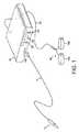
図1を参照すると、ジェネレータ10は、接続コード14を介して器具12に高周波(RF)出力を送る出力ソケット10Sを有する。ジェネレータの作動は、コード14を接続することによって器具12から、または図示のように、フットスイッチ接続コード18によってジェネレータの背部に接続されたフットスイッチ・ユニット16によって行うことができる。例示の実施形態では、フットスイッチ・ユニット16は、ジェネレータの凝固モードと切開モードとをそれぞれ選択するために、2つのフットスイッチ16Aおよび16Bを有する。ジェネレータの前面パネルは、ディスプレイ24に示される凝固および切開電力レベルをそれぞれ設定するための押しボタン20および22を有する。押しボタン26は、凝固波形および切開波形のいずれかを選択するための手段として設けられている。 Referring to FIG. 1, the
図2は、器具12の実施形態をさらに詳細に示している。器具12は、絶縁シャフト2および先端部3を有する。器具の最先端には、絶縁部材5によって第1のリターン電極6から分離されたアクティブ電極4が存在し、絶縁部材は、リターン電極を、アクティブ電極4に対して軸方向に後退させるように働く。第2のリターン電極7は、該第2のリターン電極が、第1のリターン電極に対して軸方向に後退するように、絶縁部材8によって第1のリターン電極から分離されて設けられている。このようにして、アクティブ電極4と第1のリターン電極6との間の距離は、アクティブ電極4と第2のリターン電極7との間の距離よりもはるかに小さい。 FIG. 2 shows an embodiment of the
アクティブ電極4の露出された表面積は、第1のリターン電極6または第2のリターン電極7の表面積よりも小さい。これは、電気外科手術の切開プロセスまたは凝固プロセス中に、電極4がアクティブ電極として確実に動作し、かつ電極6および7がリターン電極として確実に動作することを支援する。電極4、6および7は、後述するように、接続コード14によって電気外科用ジェネレータ10に接続されて、別々の出力接続部に接続される。 The exposed surface area of the
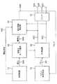
図3を参照すると、ジェネレータは、切換え回路62を介して器具12に結合するための一対の出力線60Cを有する電力発振器60の形態の高周波(RF)出力段を備える。切換え回路62は、後述するように、器具を電極に接続するための第1、第2および第3の出力接続部62A、62Bおよび62Cを有している。電力は、切換えモード電源66によって発振器60に供給される。 Referring to FIG. 3, the generator includes a radio frequency (RF) output stage in the form of a
好ましい実施形態において、RF発振器60は、約400kHzで動作するが、300kHzから上方にHF域までの任意の周波数で実施可能である。切換えモード電源は、通常、25から50kHzの範囲の周波数で動作する。出力線60Cを横断して、切換えモード電源66に結合された第1の出力68Aと、「オン」時間制御回路70に結合された第2の出力68Bとを有する電圧閾値検出器68とが接続されている。操作者の制御機構およびディスプレイ(図1で示されている)に結合されたマイクロプロセッサ制御装置72は、供給電圧を変更することによってジェネレータの出力電力を調整するための電源66の制御入力66Aに接続され、かつピークRF出力電圧限界を設定するための電圧閾値検出器68の閾値設定入力68Cに接続される。 In the preferred embodiment, the
動作時において、マイクロプロセッサ制御装置72は、ハンドピースまたはフットスイッチ(図1を参照。)に設けることのできる起動スイッチ配列を外科医が操作することによって電気外科用電力が要求されたときに、切換えモード電源66に電力が印加されるようにする。ジェネレータの前面パネル(図1を参照。)の制御設定に従って、入力68Cを介して、一定の出力電圧閾値が供給電圧とは独立して設定される。通常、乾燥または凝固のために、閾値は、150ボルトと200ボルトとの間の乾燥閾値に設定される。切開または蒸散出力が必要なときには、閾値は、250または300ボルトから600ボルトまでの範囲の値に設定される。これらの電圧値はピーク値である。電圧値がピーク値であるということは、乾燥または凝固させるためには、少なくとも、電圧が所の値にクランプされる前に最大電力を与えるように低波高率の出力RF波形を有することが好ましいことを意味する。通常、1.5以下の波高因子が得られる。 In operation, the
ジェネレータが最初に作動されたとき、RF発振器60(「オン」時間制御回路70に接続される)の制御入力60Iの状態は「オン」であり、したがって、発振器60の発振素子を形成する電力切換え装置は、各RF発振サイクル中の最大導電期間(conduction period)にオンであるように切り換えられる。組織に供給される電力は、一部が、切換えモード電源66からRF発振器60に加えられる供給電圧に依存し、また一部が、組織のインピーダンスに依存する。乾燥出力に対する電圧閾値は、電圧閾値に達したときに、トリガ信号を「オン」時間制御回路70および切換えモード電源66送信されるように設定される。「オン」時間制御回路70は、RF発振器−切換え装置の「オン」時間を実質的に即時に低下させる効果を有する。同時に、切換えモード電源は、発振器60に供給される電圧が低下し始めるように無効化される。このようなジェネレータの動作は、欧州特許出願公開第0754437号明細書に詳細に記載されており、その開示を参照によって本明細書に組み込む。 When the generator is first activated, the state of the control input 60I of the RF oscillator 60 (connected to the “on” time control circuit 70) is “on”, and thus the power switching that forms the oscillating element of the
ジェネレータ10からの出力接続部62A、62Bおよび62Cは、リード14を介してそれぞれ3つの電極4、6および7(図2)に電気的に接続される。器具12を切開モードで動作させたいとき、フットスイッチ16Aが押下され、これによって、切換え回路62をその「切開」位置に設定する制御装置72へ信号が送信される。これは図4Aで示されており、同図において、発振器60からの信号は、第1の出力接続部62Aおよび第2の出力接続部62Bとの間で接続される。これは、RF電力信号が、切開電極4と第1のリターン電極6との間に印加されることを意味する。第3のまたは出力接続部62C(したがって、第2のリターン電極7)には通電されない。 The
制御装置72は、切換え回路を図4Aの位置に設定するのと同時に、線68Cを介して電圧閾値検出器68にも信号を送り、ピーク出力電圧限界を比較的高い「切開」レベルに設定する。この切開信号の制御は、前に参照した欧州特許出願公開第0754437号明細書さらに詳細に述べられている。切開モードにおいて、ジェネレータからの出力は、結果として低電流レベルとなる比較的高電圧であり、アクティブ電極4および6と第1のリターン電極との間の距離が比較的小さいことによって、器具の先端が導電性の液に浸漬されている場合であっても、確実に電極アッセンブリを作動させて組織を切開することができる。 At the same time the
もう1つの方法として、器具12を凝固モードで動作させたいとき、フットスイッチ16Bが押下され、これによって、図4Bで示されるように、制御装置72が切換え回路62をその「凝固」状態に設定するようになる。この設定において、発振器からの電力信号は、第1の出力接続部62Aおよび第3の出力接続部62Cとの間で接続される。これは、RF電力信号が、アクティブ電極4と第2のリターン電極7との間に印加されることを意味する。同時に、欧州特許出願公開第0754437号明細書にもさらに具体的に述べられているように、制御装置は、信号を電圧閾値検出器68に送り、ピーク出力電圧限界を比較的低い「凝固」レベルに設定する。「凝固」モードにおいて、ジェネレータからの出力は、対応する比較的高電流を含む比較的低電圧であり、アクティブ電極4と第2のリターン電極7との間の距離が比較的大きいことによって、有効範囲の凝固を確実に生成することができる。 Alternatively, when it is desired to operate the
別のスイッチ配列(図示せず)において、器具12が、凝固モードで動作されるとき、切換え回路は、発振器からの電力信号を、第1の出力接続部62Aと、第2の出力接続部62Bおよび第3の出力接続部62Cの両方との間で接続する。このようにして、リターン電極6、7の両方が凝固プロセスにおいて使用されて、アクティブ電極4と第1のリターン電極6との間で比較的正確に凝固させることができ、かつアクティブ電極4と第2のリターン電極7との間で比較的広範囲を凝固させることができる。 In another switch arrangement (not shown), when the
図5は、アクティブ電極4および第1のリターン電極6の両方が器具の先端に配置されているもう1つの器具12を示している。単一の絶縁部材5が、これら2つの電極4、6を、互いから、さらにアクティブ電極4および第1のリターン電極6から軸方向に後退された第2のリターン電極7からも分離するために設けられている。器具の動作は、前に述べたものと同様であり、ジェネレータ10からの切開信号は、第1および第2の出力接続部62A、62Bに、したがって、アクティブ電極4および第1のリターン電極6に供給される。このようにして、電気外科手術の切開は、器具の先端に存在する2つの電極4、6の間で行われる。この状態において、第1のリターン電極6は、切開動作のためのリターン電極として機能する。 FIG. 5 shows another
凝固が必要なとき、ジェネレータからの凝固出力は、第1および第3の出力接続部62A、62Cに、したがって、アクティブ電極4および第2のリターン電極7に供給される。この構成においては任意で、第1および第2の出力接続部62A、62Bを、凝固段階の間も一緒に接続することもでき、したがって、凝固は、アクティブ電極4および第1のリターン電極6の両方または片方である一方と、第2のリターン電極7である他方との間で行われる。この状態において、第1のリターン電極6は、凝固動作に対してもう1つのアクティブ電極として動作している。 When coagulation is required, the coagulation output from the generator is supplied to the first and
図6は、別の実施形態を示しており、この実施形態において、図で示すように、アクティブ電極4は器具12の先端に存在し、第1のリターン電極6がアクティブ電極4を囲んでいる。この場合、第1のリターン電極6は、器具の先端部3の前方を向いている表面部分上に露出した環状の表面を有する。絶縁部材5は、アクティブ電極4を第1のリターン電極6から分離しており、また他の絶縁部材8が、これらの2つの電極4、6を軸方向に後退した第2のリターン電極7から分離している。この装置の動作は、前述したように、電気外科手術の切開が、比較的短い距離を挟むアクティブ電極4と第1のリターン電極6との間の比較的短い距離にわたって行われ、電気外科手術の凝固が、アクティブ電極4と第2のリターン電極7の間の十分に大きな距離にわたって行われる。 FIG. 6 shows another embodiment, in which the
図7は、図2および5で示した先の実施形態からの特徴の組合せを用いた4電極の器具を示す。アクティブ電極4および第1のリターン電極6は、絶縁部材5によって互いに分離され、かつ第1の2つの電極4、6から軸方向に後退した第2のリターン電極7からも分離されて、器具12の先端上に共に存在している。しかし、さらなる絶縁部材11によって第2のリターン電極7から軸方向に後退した第3のリターン電極9がさらに設けられている。ジェネレータは、切換え手段62(図3を参照のこと)によって選択されて、第3のリターン電極9に接続できるさらなる出力接続部を有する。このようにして、器具は、「切開」、「局所的な凝固」および「広範囲の凝固」の3つの異なる設定を有する。切開モードにおいては、切開用のRF波形がアクティブ電極4と第1のリターン電極6との間に送られる。局所的な凝固モードにおいては、凝固用のRF波形がアクティブ電極と第2のリターン電極7との間に送られる。広範囲の凝固モードにおいては、凝固用のRF波形がアクティブ電極と第3のリターン電極9との間に送られる。それぞれの場合において、広範囲の凝固が、局所的な凝固よりも組織の十分に広い領域にわたって行われるように、アクティブ電極と各リターン電極との間の距離が増加される。 FIG. 7 shows a four-electrode instrument using a combination of features from the previous embodiment shown in FIGS. The
図8および9は、米国特許出願公開第2009/0048592号明細書で開示されたものに基づく器具の別の実施形態を示しており、その内容全体を、参照によって本明細書に組み込む。この器具において、アクティブ電極4は、セラミック絶縁体36内に位置する。アクティブ電極4は、セラミック絶縁体36に設けられたチャンバ33内に収容される。この組織処置電極4は、タングステンまたはタングステンと白金との合金から形成される。組織処置電極4は、吸引開口4aが形成され、また、そのコーナのそれぞれに各突起部4bを備えており、該突起部は、アクティブ電極のコーナのそれぞれに電界を集中させるために設けられている。突起部4bは、アクティブ電極4の平坦な表面30と処置すべき組織との間にわずかな離間部を生成する働きもする。こうすることによって、導電性の液が、平坦な表面上を循環することを可能にし、かつ電極または組織が過熱するのを回避する。 FIGS. 8 and 9 show another embodiment of a device based on that disclosed in US 2009/0048592, the entire contents of which are hereby incorporated by reference. In this instrument, the
図9に示されるように、アクティブ電極4は、平坦な表面30および突起部4bを含む上側部分35と、成形されたキール(keel)部分32を含む下側部分31とを備える。器具を組み立てるために、アクティブ電極4は、セラミック絶縁体36内に存在するチャンバ33中へと下げられている。次いで、吸引管37が前方に押されて、アクティブ電極のキール部分32の上に位置し、それを定位置に固定する。吸引管37の前方への移動によってチャンバ33中でアクティブ電極4が前方に押され、それによってアクティブ電極が定位置に固定される。 As shown in FIG. 9, the
蒸気泡が生成される問題を低減するために、かつ組織処置電極4の周辺領域から粒状の物質(組織の破片など)の除去を支援するために、器具は、アクティブ電極中の開口4aを通して器具のシャフトを介し、蒸気泡を除去することのできる吸引ポンプ(図示せず)を備える。吸引管37は、ステンレス鋼または金めっきした銅などの導電性材料から製作され、吸引開口4aを吸引ポンプに接続する。管37は、また、アクティブ電極4をジェネレータ10に電気的に接続するための手段を構成する。 In order to reduce the problem of generating vapor bubbles and to assist in the removal of particulate matter (such as tissue debris) from the surrounding area of the
リターン電極7は、シャフト40の先端部分によって構成され、ポリテトラフルオロエチレン、ポリオレフィン、ポリエステルまたはエチレン−テトラフルオロエチレンからなるスリーブ41が、リターン電極7に隣接するシャフト40の基端部分を囲む。吸引管37は、その先端に長手方向の細長い溝42を備えて形成される。図で示すように、吸引管37の先端は、アクティブ電極4の下のセラミック絶縁体36によって画定されるチャンバ33の中へと延びる。溝42は、アクティブ電極4における開口4aと連続しており、開口4aは、約45度の角度で組織処置電極を通って傾斜している。電極4には、貫通していない凹部43が設けられている。この凹部43は、単に、電気外科用器具の自動組み立てを可能にするために設けられており、電極4の全体を貫通していないので吸引開口を提供するものではない。 The
セラミック絶縁体36は、金属のカウル(cowl)44で囲まれている。該カウル44は、第1のリターン電極6を形成し、また、外側リード45を介してジェネレータ10に接続されて、図4Aおよび4Bを参照して上記で述べた切換え回路62に接続される。器具が、組織を切開するために使用されているとき、切換え回路は、RF電力信号をアクティブ電極4とカウル44(すなわち、第1のリターン電極6)との間に供給する。しかし、器具が、組織を凝固するために使用されているとき、切換え回路は、RF電力信号をアクティブ電極4と第2のリターン電極7との間に供給する。アクティブ電極4と第1の電極6との間の距離は、アクティブ電極4と第2のリターン電極7との間の距離未満であり、したがって、器具が組織を切開するために使用されているときは、電極は比較的小さな距離を空けて離され、器具が組織を凝固させるために使用されているときは、電極は比較的大きな距離を空けて離される。 The
アクティブ電極4と第2のリターン電極7との間の最短距離を表す直線が引かれた場合、第1のリターン電極6(またはカウル44)のいずれの部分もその線上に存在しないことが理解されよう。これは、器具12が組織を凝固させるために使用されているとき、第1のリターン電極6(またはカウル44)が、アクティブ電極4と第2のリターン電極7との間の電流経路中に存在しないことを意味する。この例において、電流は、カウル44に供給されることなく、または、カウル44によって影響されることなく、アクティブ電極4と第2のリターン電極7との間の組織または導電性の液を通って流れる。同様に、アクティブ電極4とカウル44との間の最短距離を表す直線が引かれた場合、第2のリターン電極7のいずれの部分もその線上に存在しない。これは、器具が組織を切開するために使用されているとき、第2の電極7が、アクティブ電極4とカウル44との間の電流経路中に存在しないことを意味する。この例において、電流は、第2のリターン電極7に供給されることなく、または、第2のリターン電極によって影響されることなく、アクティブ電極4とリターン電極もしくはカウル44との間の組織または導電性の液を通って流れる。 When a straight line representing the shortest distance between the
図10、11、12および13で示す別の実施形態において、アクティブ電極4は、平坦な表面30に対して180°傾いた、すなわち、表面30に対して反対方向を向いたさらなる露出された組織処置表面46を有する。図10および11の器具において、導電性の吸引管37は、組織処置表面30に関連するアクティブ電極本体部分31と、さらに組織処置表面46に関連する反対側の本体部分47とに電気的に接触している。このようにして、アクティブ電極の組織処置表面30,46は共に、RF電力信号が器具に供給されたとき、同時に作動する。前述同様に、カウル44は、器具が組織を切開するために使用されているとき、組織処置表面30および46に対してリターン電極として動作する。シャフトの先端部分7は、組織処置表面30および46が組織を凝固させるために使用されているとき、リターン電極として動作する。表面46は、表面30と比較して小さな表面積を有しており、したがって、器具は、表面46を用いて組織を切開し、表面30を用いて組織を凝固させるために使用するように設計される。このようにして、器具のユーザは、組織を切開したいか、または組織を凝固したいかに応じて、器具を180°回転させて、表面30または46をそれぞれ処置すべき組織に接触させることができる。 In another embodiment shown in FIGS. 10, 11, 12 and 13, the
図8および9を参照して上記で述べた実施形態と同様に、図10から11の器具によれば、リターン電極44、7が互いにずれた位置に配置されている電極配置が提供されることが理解されよう。組織処置表面30と第2のリターン電極7の間の最短距離を表す直線が引かれる場合、第1のリターン電極、すなわち、カウル44のいずれの部分もその直線上に存在しない。同様に、組織処置表面46と第2のリターン電極7との間の最短距離を表す直線が引かれる場合、カウル44のいずれの部分もその直線上に存在しない。このようにして、カウル44は、器具が組織を凝固させるために使用されている場合、処置表面30、46と第2のリターン電極7との間の電流経路と干渉しない。同様にして、表面30とカウル44との間の最短距離を表す直線が引かれる場合、第2のリターン電極7のいずれの部分もその直線上に存在しない。同様に、表面46とカウル44との間の最短距離を表す直線が引かれる場合、第2のリターン電極7のいずれの部分もその直線上に存在しない。このようにして、第2のリターン電極7は、器具が組織を切開するために使用されている場合、組織処置表面30、46とカウル44との間の電流経路と干渉しない。 Similar to the embodiment described above with reference to FIGS. 8 and 9, the instrument of FIGS. 10 to 11 provides an electrode arrangement in which the
本発明の範囲から逸脱することなく、電極とジェネレータ切換えのさらなる組合せが可能であることが理解されよう。器具は、防湿(dry−field)器具として、直接組織に接触させて使用することができるが、あるいはウェットフィールド(wet−field)器具として導電性の液に浸漬させて使用することができる。切換え回路62は、切開モードと凝固モードとの間を単に切り換えるために使用でき、あるいは、参照によってその内容が組み込まれる米国特許第6966907号明細書においてさらに詳細に述べられているように、2つの状態間を迅速に切り替える切開・凝固混合モードを提供するために使用することができる。当業者であれば、各手技の要件、または外科医の好みに応じて、これらの様々な変形形態をどのようにして使用できるかを理解されよう。 It will be appreciated that further combinations of electrode and generator switching are possible without departing from the scope of the present invention. The device can be used in direct contact with tissue as a dry-field device, or it can be used as a wet-field device immersed in a conductive liquid. The switching
Claims (9)
Translated fromJapanese前記第1の電極が、アクティブ電極を構成するように適合された特性を有し、前記第2の電極が、第1のリターン電極を構成するように適合された特性を有し、前記第3の電極が、第2のリターン電極を構成するように適合された特性を有し、
前記器具が、使用時に前記第1の電極と前記第2の電極との間で電流経路が確立されるように、前記第1の電極を前記第2の電極を含む回路内に配置させる第1の組の接続部と、使用時に前記第1の電極と前記第3の電極との間で電流経路が確立されるように、前記第1の電極を前記第3の電極を含む回路内に配置させる第2の組の接続部とを有し、
前記第1の電極、前記第2の電極および前記第3の電極は、前記第1の電極および前記第2の電極の使用中には、前記第3の電極が前記第1の電極と前記第2の電極との間の前記電流経路中に存在せず、前記第1の電極および前記第3の電極の使用中には、前記第2の電極が前記第1の電極と前記第3の電極との間の前記電流経路中に存在しないように、前記第1の電極と前記第2の電極との間の最短距離を表す直線が引かれた場合、前記第3の電極のいずれの部分もその直線上に存在せず、また、前記第1の電極と前記第3の電極との間の最短距離を表す直線が引かれた場合、前記第2の電極のいずれの部分もその直線上に存在しないように互いに固定された関係で配置されている電気外科用器具。An electrosurgical instrument comprising at least a first electrode, a second electrode, and a third electrode, each spaced apart by an insulating member therebetween,
The first electrode has characteristics adapted to constitute an active electrode, the second electrode has characteristics adapted to constitute a first return electrode, and the third electrode The electrodes have characteristics adapted to form a second return electrode;
A first arrangement in which the instrument places the first electrode in a circuit including the second electrode so that, in use, a current path is established between the first electrode and the second electrode; The first electrode is disposed in a circuit including the third electrode so that a current path is established between the first connection electrode and the third electrode in use. A second set of connections to be
The first electrode, the second electrode, and the third electrode are the same as the first electrode and the third electrode when the first electrode and the second electrode are in use. The second electrode is not present in the current path between the first electrode and the third electrode, and the second electrode is in contact with the first electrode and the third electrode during use of the first electrode and the third electrode. When a straight line representing the shortest distance between the first electrode and the second electrode is drawn so as not to exist in the current path between the first electrode and any of the third electrodes, If a straight line representing the shortest distance between the first electrode and the third electrode is drawn on the straight line, any part of the second electrode is on the straight line. An electrosurgical instrument that is placed in a fixed relationship with one another so that it does not exist.
前記電気外科用器具が、それらの間の絶縁部材によってそれぞれ互いに間隔を空けて配置された少なくとも第1の電極、第2の電極および第3の電極を含み、前記第1の電極が、アクティブ電極を構成するように適合された特性を有し、前記第2の電極が、第1のリターン電極を構成するように適合された特性を有し、前記第3の電極が、第2のリターン電極を構成するように適合された特性を有し、
前記電気外科用ジェネレータが、高周波エネルギの供給源と、前記電気外科用器具の前記第1の電極、前記第2の電極および前記第3の電極にそれぞれ接続された第1の出力接続部、第2の出力接続部および第3の出力接続部とを含み、
前記システムは、切換え手段と制御装置とをさらに含み、該制御装置が、前記高周波エネルギを、前記第1の出力接続部および前記第2の出力接続部に、したがって、前記第1の電極が前記アクティブ電極となり前記第2の電極が前記リターン電極となるように前記第1の電極および前記第2の電極に、または、前記第1の出力接続部および前記第3の出力接続部に、したがって、前記第1の電極が前記アクティブ電極となり前記第3の電極が前記リターン電極となるように前記第1の電極および前記第3の電極に、選択的に送るように、前記切換え手段を制御可能であり、
前記第1の電極、前記第2の電極および前記第3の電極は、前記第1の電極および前記第2の電極の使用中には、前記第3の電極が前記第1の電極と前記第2の電極との間の電流経路中に存在せず、前記第1の電極および前記第3の電極の使用中には、前記第2の電極が前記第1の電極と前記第3の電極との間の電流経路中に存在しないように、前記第1の電極と前記第2の電極との間の最短距離を表す直線が引かれた場合、前記第3の電極のいずれの部分もその直線上に存在せず、また、前記第1の電極と前記第3の電極との間の最短距離を表す直線が引かれた場合、前記第2の電極のいずれの部分もその直線上に存在しないように互いに固定された関係で配置されている電気外科用システム。An electrosurgical system including an electrosurgical instrument and an electrosurgical generator,
The electrosurgical instrument includes at least a first electrode, a second electrode, and a third electrode that are spaced apart from each other by an insulating member therebetween, the first electrode being an active electrode The second electrode has a characteristic adapted to constitute a first return electrode, and the third electrode has a second return electrode. Having characteristics adapted to constitute
The electrosurgical generator includes a source of high frequency energy, a first output connection connected to the first electrode, the second electrode, and the third electrode of the electrosurgical instrument, respectively, Two output connections and a third output connection;
The system further includes switching means and a control device, wherein the control device directs the high frequency energy to the first output connection and the second output connection, and thusthe first electrode is the The first electrode and the second electrodeso that it becomes the active electrode and the second electrode becomes the return electrode , or the first output connection and the third output connection, and thereforeThe switching means can be controlled to selectively send the first electrode and the third electrodeso that the first electrodebecomes the active electrode and the third electrode becomes the return electrode. Yes,
The first electrode, the second electrode, and the third electrode are the same as the first electrode and the third electrode when the first electrode and the second electrode are in use. The second electrode is not present in the current path between the first electrode and the third electrode, and the second electrode is connected to the first electrode and the third electrode during use of the first electrode and the third electrode. When a straight line representing the shortest distance between the first electrode and the second electrode is drawn so that it does not exist in the current path between the first electrode and the second electrode, any part of the third electrode is the straight line. If a straight line representing the shortest distance between the first electrode and the third electrode is drawn, no part of the second electrode exists on the straight line. Electrosurgical systems that are arranged in a fixed relationship with each other.
前記システムが、切換え手段と、切換え回路とをさらに含み、
該切換え回路が、切開用のRF波形が選択されたとき、前記第1の出力接続部と前記第2の出力接続部との間に、したがって、前記第1の電極と前記第2の電極との間に前記切開用のRF波形を送り、凝固用のRF波形が選択されたとき、前記第1の出力接続部と前記第3の出力接続部との間に、したがって、前記第1の電極と前記第3の電極との間に前記凝固用のRF波形を送る請求項8に記載の電気外科用システム。
The electrosurgical generator includes a source of high frequency energy capable of generating a coagulation RF waveform and an incision RF waveform;
The system further includes switching means and a switching circuit,
When the switching circuit selects an incision RF waveform, between the first output connection and the second output connection, and therefore, the first electrode and the second electrode, When the RF waveform for incision is sent between the first output connection portion and the third output connection portion when the RF waveform for coagulation is selected, the first electrode 9. The electrosurgical system according to claim 8, wherein the coagulation RF waveform is sent between the first electrode and the third electrode.
Applications Claiming Priority (3)
| Application Number | Priority Date | Filing Date | Title |
|---|---|---|---|
| US28238210P | 2010-02-01 | 2010-02-01 | |
| US61/282,382 | 2010-02-01 | ||
| PCT/GB2011/000101WO2011092464A1 (en) | 2010-02-01 | 2011-01-26 | Electrosurgical instrument and system |
Publications (2)
| Publication Number | Publication Date |
|---|---|
| JP2013517881A JP2013517881A (en) | 2013-05-20 |
| JP5785957B2true JP5785957B2 (en) | 2015-09-30 |
Family
ID=43781855
Family Applications (1)
| Application Number | Title | Priority Date | Filing Date |
|---|---|---|---|
| JP2012550508AActiveJP5785957B2 (en) | 2010-02-01 | 2011-01-26 | Electrosurgical instruments and systems |
Country Status (5)
| Country | Link |
|---|---|
| EP (1) | EP2531132B1 (en) |
| JP (1) | JP5785957B2 (en) |
| AU (1) | AU2011209581B2 (en) |
| CA (1) | CA2788397C (en) |
| WO (1) | WO2011092464A1 (en) |
Families Citing this family (19)
| Publication number | Priority date | Publication date | Assignee | Title |
|---|---|---|---|---|
| US11090104B2 (en) | 2009-10-09 | 2021-08-17 | Cilag Gmbh International | Surgical generator for ultrasonic and electrosurgical devices |
| RU2017123029A (en) | 2014-12-03 | 2019-01-09 | Конинклейке Филипс Н.В. | SKIN RADIO FREQUENCY |
| US11141213B2 (en)* | 2015-06-30 | 2021-10-12 | Cilag Gmbh International | Surgical instrument with user adaptable techniques |
| EP3144245A1 (en) | 2015-09-15 | 2017-03-22 | Mould & Matic Solutions GmbH | Closing cap |
| US11076909B2 (en) | 2015-09-25 | 2021-08-03 | Gyrus Acmi, Inc. | Multifunctional medical device |
| US11020166B2 (en)* | 2015-09-25 | 2021-06-01 | Gyrus Acmi, Inc. | Multifunctional medical device |
| US11129670B2 (en) | 2016-01-15 | 2021-09-28 | Cilag Gmbh International | Modular battery powered handheld surgical instrument with selective application of energy based on button displacement, intensity, or local tissue characterization |
| US11051840B2 (en) | 2016-01-15 | 2021-07-06 | Ethicon Llc | Modular battery powered handheld surgical instrument with reusable asymmetric handle housing |
| US11266430B2 (en) | 2016-11-29 | 2022-03-08 | Cilag Gmbh International | End effector control and calibration |
| US11786294B2 (en) | 2019-12-30 | 2023-10-17 | Cilag Gmbh International | Control program for modular combination energy device |
| US20210196357A1 (en) | 2019-12-30 | 2021-07-01 | Ethicon Llc | Electrosurgical instrument with asynchronous energizing electrodes |
| US12076006B2 (en) | 2019-12-30 | 2024-09-03 | Cilag Gmbh International | Surgical instrument comprising an orientation detection system |
| US12262937B2 (en) | 2019-12-30 | 2025-04-01 | Cilag Gmbh International | User interface for surgical instrument with combination energy modality end-effector |
| US11950797B2 (en) | 2019-12-30 | 2024-04-09 | Cilag Gmbh International | Deflectable electrode with higher distal bias relative to proximal bias |
| US12343063B2 (en) | 2019-12-30 | 2025-07-01 | Cilag Gmbh International | Multi-layer clamp arm pad for enhanced versatility and performance of a surgical device |
| US12023086B2 (en) | 2019-12-30 | 2024-07-02 | Cilag Gmbh International | Electrosurgical instrument for delivering blended energy modalities to tissue |
| US12053224B2 (en) | 2019-12-30 | 2024-08-06 | Cilag Gmbh International | Variation in electrode parameters and deflectable electrode to modify energy density and tissue interaction |
| US12336747B2 (en) | 2019-12-30 | 2025-06-24 | Cilag Gmbh International | Method of operating a combination ultrasonic / bipolar RF surgical device with a combination energy modality end-effector |
| CN112155715A (en)* | 2020-10-14 | 2021-01-01 | 珠海维尔康生物科技有限公司 | Electrode cutting device for cutting soft tissue based on radio frequency ablation |
Family Cites Families (11)
| Publication number | Priority date | Publication date | Assignee | Title |
|---|---|---|---|---|
| US6974453B2 (en)* | 1993-05-10 | 2005-12-13 | Arthrocare Corporation | Dual mode electrosurgical clamping probe and related methods |
| US6203542B1 (en)* | 1995-06-07 | 2001-03-20 | Arthrocare Corporation | Method for electrosurgical treatment of submucosal tissue |
| US6837888B2 (en)* | 1995-06-07 | 2005-01-04 | Arthrocare Corporation | Electrosurgical probe with movable return electrode and methods related thereto |
| US6837887B2 (en)* | 1995-06-07 | 2005-01-04 | Arthrocare Corporation | Articulated electrosurgical probe and methods |
| EP1025807B1 (en) | 1995-06-23 | 2004-12-08 | Gyrus Medical Limited | An electrosurgical instrument |
| KR19990028365A (en)* | 1995-06-23 | 1999-04-15 | 니겔 마크 고블 | Electrosurgical surgical instruments |
| US6293942B1 (en) | 1995-06-23 | 2001-09-25 | Gyrus Medical Limited | Electrosurgical generator method |
| US6228082B1 (en)* | 1995-11-22 | 2001-05-08 | Arthrocare Corporation | Systems and methods for electrosurgical treatment of vascular disorders |
| EP1287788B1 (en) | 2001-08-27 | 2011-04-20 | Gyrus Medical Limited | Electrosurgical system |
| US6966907B2 (en) | 2001-08-27 | 2005-11-22 | Gyrus Medical Limited | Electrosurgical generator and system |
| GB2451623A (en) | 2007-08-03 | 2009-02-11 | Gyrus Medical Ltd | Electrosurgical Instrument for underwater surgery with aspiration aperture in electrode |
- 2011
- 2011-01-26WOPCT/GB2011/000101patent/WO2011092464A1/enactiveApplication Filing
- 2011-01-26JPJP2012550508Apatent/JP5785957B2/enactiveActive
- 2011-01-26EPEP11702489.3Apatent/EP2531132B1/enactiveActive
- 2011-01-26CACA2788397Apatent/CA2788397C/enactiveActive
- 2011-01-26AUAU2011209581Apatent/AU2011209581B2/enactiveActive
Also Published As
| Publication number | Publication date |
|---|---|
| AU2011209581B2 (en) | 2015-09-03 |
| CA2788397A1 (en) | 2011-08-04 |
| WO2011092464A1 (en) | 2011-08-04 |
| JP2013517881A (en) | 2013-05-20 |
| CA2788397C (en) | 2019-01-15 |
| AU2011209581A1 (en) | 2012-09-20 |
| AU2011209581A2 (en) | 2012-09-20 |
| EP2531132B1 (en) | 2015-07-29 |
| EP2531132A1 (en) | 2012-12-12 |
Similar Documents
| Publication | Publication Date | Title |
|---|---|---|
| JP5785957B2 (en) | Electrosurgical instruments and systems | |
| US8333761B2 (en) | Electrosurgical instrument and system | |
| US8840610B2 (en) | Electrosurgical system including electrosurgical instrument for longitudinal and lateral treatment | |
| JP5747044B2 (en) | Electrosurgical instrument with two active electrodes optimized for transpiration and coagulation | |
| JP6090809B2 (en) | Electrosurgical system | |
| AU2011209579B2 (en) | Electrosurgical instrument | |
| AU2011209579A2 (en) | Electrosurgical instrument | |
| US8518034B2 (en) | Electrosurgical instrument and system | |
| WO2012136957A1 (en) | Electrosurgical system |
Legal Events
| Date | Code | Title | Description |
|---|---|---|---|
| A621 | Written request for application examination | Free format text:JAPANESE INTERMEDIATE CODE: A621 Effective date:20140108 | |
| A977 | Report on retrieval | Free format text:JAPANESE INTERMEDIATE CODE: A971007 Effective date:20140924 | |
| A131 | Notification of reasons for refusal | Free format text:JAPANESE INTERMEDIATE CODE: A131 Effective date:20141007 | |
| A521 | Request for written amendment filed | Free format text:JAPANESE INTERMEDIATE CODE: A523 Effective date:20150107 | |
| TRDD | Decision of grant or rejection written | ||
| A01 | Written decision to grant a patent or to grant a registration (utility model) | Free format text:JAPANESE INTERMEDIATE CODE: A01 Effective date:20150630 | |
| A61 | First payment of annual fees (during grant procedure) | Free format text:JAPANESE INTERMEDIATE CODE: A61 Effective date:20150727 | |
| R150 | Certificate of patent or registration of utility model | Ref document number:5785957 Country of ref document:JP Free format text:JAPANESE INTERMEDIATE CODE: R150 | |
| R250 | Receipt of annual fees | Free format text:JAPANESE INTERMEDIATE CODE: R250 | |
| R250 | Receipt of annual fees | Free format text:JAPANESE INTERMEDIATE CODE: R250 | |
| R250 | Receipt of annual fees | Free format text:JAPANESE INTERMEDIATE CODE: R250 | |
| R250 | Receipt of annual fees | Free format text:JAPANESE INTERMEDIATE CODE: R250 | |
| R250 | Receipt of annual fees | Free format text:JAPANESE INTERMEDIATE CODE: R250 | |
| R250 | Receipt of annual fees | Free format text:JAPANESE INTERMEDIATE CODE: R250 | |
| R250 | Receipt of annual fees | Free format text:JAPANESE INTERMEDIATE CODE: R250 | |
| R250 | Receipt of annual fees | Free format text:JAPANESE INTERMEDIATE CODE: R250 |