JP5785823B2 - Bottle - Google Patents
BottleDownload PDFInfo
- Publication number
- JP5785823B2 JP5785823B2JP2011187491AJP2011187491AJP5785823B2JP 5785823 B2JP5785823 B2JP 5785823B2JP 2011187491 AJP2011187491 AJP 2011187491AJP 2011187491 AJP2011187491 AJP 2011187491AJP 5785823 B2JP5785823 B2JP 5785823B2
- Authority
- JP
- Japan
- Prior art keywords
- wall portion
- bottle
- movable wall
- radial direction
- peripheral wall
- Prior art date
- Legal status (The legal status is an assumption and is not a legal conclusion. Google has not performed a legal analysis and makes no representation as to the accuracy of the status listed.)
- Active
Links
- 230000002093peripheral effectEffects0.000claimsdescription39
- 230000000630rising effectEffects0.000claimsdescription19
- 230000000994depressogenic effectEffects0.000claimsdescription14
- 239000000463materialSubstances0.000claimsdescription9
- 229920003002synthetic resinPolymers0.000claimsdescription5
- 239000000057synthetic resinSubstances0.000claimsdescription5
- 238000010521absorption reactionMethods0.000description9
- 230000008859changeEffects0.000description6
- 239000010410layerSubstances0.000description5
- 230000006837decompressionEffects0.000description4
- 238000009751slip formingMethods0.000description4
- 230000006872improvementEffects0.000description3
- 239000000470constituentSubstances0.000description2
- -1polyethylene terephthalatePolymers0.000description2
- 229920005989resinPolymers0.000description2
- 239000011347resinSubstances0.000description2
- QVGXLLKOCUKJST-UHFFFAOYSA-Natomic oxygenChemical compound[O]QVGXLLKOCUKJST-UHFFFAOYSA-N0.000description1
- 230000004888barrier functionEffects0.000description1
- 238000000071blow mouldingMethods0.000description1
- 239000007789gasSubstances0.000description1
- 238000001746injection mouldingMethods0.000description1
- 239000000203mixtureSubstances0.000description1
- 230000004048modificationEffects0.000description1
- 238000012986modificationMethods0.000description1
- 239000001301oxygenSubstances0.000description1
- 229910052760oxygenInorganic materials0.000description1
- 229920003207poly(ethylene-2,6-naphthalate)Polymers0.000description1
- 229920000728polyesterPolymers0.000description1
- 239000011112polyethylene naphthalateSubstances0.000description1
- 229920000139polyethylene terephthalatePolymers0.000description1
- 239000005020polyethylene terephthalateSubstances0.000description1
- 230000009467reductionEffects0.000description1
- 239000002356single layerSubstances0.000description1
Images

Classifications
- B—PERFORMING OPERATIONS; TRANSPORTING
- B65—CONVEYING; PACKING; STORING; HANDLING THIN OR FILAMENTARY MATERIAL
- B65D—CONTAINERS FOR STORAGE OR TRANSPORT OF ARTICLES OR MATERIALS, e.g. BAGS, BARRELS, BOTTLES, BOXES, CANS, CARTONS, CRATES, DRUMS, JARS, TANKS, HOPPERS, FORWARDING CONTAINERS; ACCESSORIES, CLOSURES, OR FITTINGS THEREFOR; PACKAGING ELEMENTS; PACKAGES
- B65D23/00—Details of bottles or jars not otherwise provided for
- B65D23/001—Supporting means fixed to the container
- B—PERFORMING OPERATIONS; TRANSPORTING
- B65—CONVEYING; PACKING; STORING; HANDLING THIN OR FILAMENTARY MATERIAL
- B65D—CONTAINERS FOR STORAGE OR TRANSPORT OF ARTICLES OR MATERIALS, e.g. BAGS, BARRELS, BOTTLES, BOXES, CANS, CARTONS, CRATES, DRUMS, JARS, TANKS, HOPPERS, FORWARDING CONTAINERS; ACCESSORIES, CLOSURES, OR FITTINGS THEREFOR; PACKAGING ELEMENTS; PACKAGES
- B65D79/00—Kinds or details of packages, not otherwise provided for
- B65D79/005—Packages having deformable parts for indicating or neutralizing internal pressure-variations by other means than venting
- B65D79/008—Packages having deformable parts for indicating or neutralizing internal pressure-variations by other means than venting the deformable part being located in a rigid or semi-rigid container, e.g. in bottles or jars
- B65D79/0081—Packages having deformable parts for indicating or neutralizing internal pressure-variations by other means than venting the deformable part being located in a rigid or semi-rigid container, e.g. in bottles or jars in the bottom part thereof
- B—PERFORMING OPERATIONS; TRANSPORTING
- B65—CONVEYING; PACKING; STORING; HANDLING THIN OR FILAMENTARY MATERIAL
- B65D—CONTAINERS FOR STORAGE OR TRANSPORT OF ARTICLES OR MATERIALS, e.g. BAGS, BARRELS, BOTTLES, BOXES, CANS, CARTONS, CRATES, DRUMS, JARS, TANKS, HOPPERS, FORWARDING CONTAINERS; ACCESSORIES, CLOSURES, OR FITTINGS THEREFOR; PACKAGING ELEMENTS; PACKAGES
- B65D1/00—Rigid or semi-rigid containers having bodies formed in one piece, e.g. by casting metallic material, by moulding plastics, by blowing vitreous material, by throwing ceramic material, by moulding pulped fibrous material or by deep-drawing operations performed on sheet material
- B65D1/02—Bottles or similar containers with necks or like restricted apertures, designed for pouring contents
- B65D1/0223—Bottles or similar containers with necks or like restricted apertures, designed for pouring contents characterised by shape
- B65D1/0261—Bottom construction
- B65D1/0276—Bottom construction having a continuous contact surface, e.g. Champagne-type bottom
Landscapes
- Engineering & Computer Science (AREA)
- Mechanical Engineering (AREA)
- Ceramic Engineering (AREA)
- Containers Having Bodies Formed In One Piece (AREA)
Description
Translated fromJapanese本発明は、ボトルに関する。 The present invention relates to a bottle.
従来から、合成樹脂材料で有底筒状に形成されたボトルとして、例えば下記特許文献1に示されるように、底部の底壁部が、外周縁部に位置する接地部と、該接地部にボトル径方向の内側から連なり上方に向けて延びる立ち上がり周壁部と、該立ち上がり周壁部の上端部からボトル径方向の内側に向けて突出する可動壁部と、該可動壁部のボトル径方向の内端部から上方に向けて延びる陥没周壁部と、を備え、可動壁部が陥没周壁部を上方に向けて移動させるように、立ち上がり周壁部との接続部分を中心に回動することにより、ボトル内の減圧を吸収する構成が知られている。 Conventionally, as a bottle formed into a bottomed cylindrical shape with a synthetic resin material, for example, as shown in Patent Document 1 below, the bottom wall portion of the bottom portion is connected to a grounding portion located on the outer peripheral edge portion, and the grounding portion. A rising peripheral wall portion extending from the inside in the bottle radial direction and extending upward; a movable wall portion protruding from the upper end portion of the rising peripheral wall portion toward the inside in the bottle radial direction; and an inner portion of the movable wall portion in the bottle radial direction. A bottle by rotating around a connecting portion with the rising peripheral wall so that the movable wall moves the depressed peripheral wall upward. A configuration that absorbs the reduced pressure inside is known.
しかしながら、前記従来のボトルでは、ボトル内の減圧吸収性能を向上させることに対して改善の余地があった。
ここで、減圧吸収性能を向上させるためには、可動壁部の上方への移動量を確保する必要がある。そのためには、可動壁部と立ち上がり周壁部との接続部分において、可動壁部の接線と水平面とのなす角度(俯角)を、例えば、水平面に対して45度程度と大きくして、可動壁部を可能な限り下方に位置させた形状にすることが考えられる。しかしながら、この場合には可動壁部の上方へ向けた移動量は確保し易くなるものの、可動壁部が上方に移動し難くなるという問題がある。However, the conventional bottle has room for improvement with respect to improving the vacuum absorption performance in the bottle.
Here, in order to improve the reduced-pressure absorption performance, it is necessary to ensure the amount of upward movement of the movable wall portion. For this purpose, at the connecting portion between the movable wall portion and the rising peripheral wall portion, the angle (inclination) formed between the tangent line of the movable wall portion and the horizontal plane is increased to, for example, about 45 degrees with respect to the horizontal plane. It is conceivable to make the shape as low as possible. However, in this case, although it is easy to ensure the amount of movement of the movable wall portion upward, there is a problem that the movable wall portion is difficult to move upward.
そこで、本発明は、前述した事情に鑑みてなされたものであって、その目的は、ボトル内の減圧吸収性能の向上を図った上で、可動壁部をスムーズに移動させることができるボトルを提供することである。 Therefore, the present invention has been made in view of the circumstances described above, and its purpose is to improve the decompression absorption performance in the bottle and to move the movable wall portion smoothly. Is to provide.
上記課題を解決するために、本発明は以下の手段を提案している。
本発明に係るボトルは、合成樹脂材料で形成された有底筒状のボトルであって、底部の底壁部が、外周縁部に位置する接地部と、該接地部にボトル径方向の内側から連なり上方に向けて延びる立ち上がり周壁部と、該立ち上がり周壁部の上端部からボトル径方向の内側に向けて突出する可動壁部と、該可動壁部のボトル径方向の内端部から上方に向けて延びる陥没周壁部と、を備え、前記可動壁部は、前記立ち上がり周壁部との接続部分を中心に前記陥没周壁部とともに上方に向けて移動自在に配設され、前記可動壁部におけるボトル径方向に沿う外端部には、ボトル軸方向に沿う縦断面視で前記可動壁部の法線方向に沿って上方に膨出する上方膨出部が形成されていることを特徴としている。In order to solve the above problems, the present invention proposes the following means.
The bottle according to the present invention is a bottomed cylindrical bottle formed of a synthetic resin material, the bottom wall portion of the bottom portion is a grounding portion located at the outer peripheral edge portion, and the grounding portion on the inner side in the bottle radial direction A rising peripheral wall portion that extends upward from the upper end portion, a movable wall portion that protrudes inward in the bottle radial direction from the upper end portion of the rising peripheral wall portion, and an upper end from the inner end portion of the movable wall portion in the bottle radial direction. And the movable wall portion is arranged to be movable upward together with the depressed peripheral wall portion around the connecting portion with the rising peripheral wall portion, and the bottle in the movable wall portion The outer end portion along the radial direction is formed with an upper bulging portion that bulgesupward along the normal direction of the movable wall portion in alongitudinal sectional view along thebottle axial direction .
このような特徴により、可動壁部と立ち上がり周壁部との接続部分を中心にして可動壁部が移動する際に、上方膨出部が可動壁部の初動時の起点となる。この場合、ボトルの内圧変化に応じて上方膨出部が上方に移動し始めることで、これに追従して可動壁部全体が上方に移動することになる。これにより、ボトルの内圧変化に応じて可動壁部全体をスムーズに移動させることができる。
したがって、可動壁部と立ち上がり周壁部との接続部分において、可動壁部の接線と水平面とのなす角度(俯角)を大きくして、減圧吸収性能の向上を図った場合であっても、可動壁部が上方に移動し難くなるのを抑制できる。その結果、ボトル内の減圧吸収性能の向上を図った上で、可動壁部をスムーズに移動させることができる。With such a feature, when the movable wall portion moves around the connecting portion between the movable wall portion and the rising peripheral wall portion, the upward bulging portion becomes a starting point when the movable wall portion is initially moved. In this case, when the upper bulging portion starts to move upward in accordance with the change in the internal pressure of the bottle, the entire movable wall portion moves upward following this. Thereby, the whole movable wall part can be smoothly moved according to the internal pressure change of a bottle.
Therefore, even when the angle between the tangent line of the movable wall portion and the horizontal plane (the depression angle) is increased at the connecting portion between the movable wall portion and the rising peripheral wall portion, It can suppress that a part becomes difficult to move upwards. As a result, it is possible to smoothly move the movable wall portion while improving the vacuum absorption performance in the bottle.
また、前記可動壁部のうち、前記上方膨出部よりもボトル径方向の内側に位置する部分には、下方に向けて窪んだ下方膨出部が形成されていてもよい。 In addition, a lower bulging portion that is recessed downward may be formed in a portion of the movable wall portion that is located on the inner side in the bottle radial direction from the upper bulging portion.
この場合、可動壁部のボトル径方向に沿う外端部から内端部までの長さが、立ち上がり周壁部におけるボトル径方向の内端部と、陥没周壁部におけるボトル径方向の外端部と、を結ぶ可動壁部の表面形状に倣って延びる仮想線の接線に沿う長さよりも長くなる。これにより、可動壁部の移動量を確保できるので、減圧吸収性能の更なる向上を図ることができる。 In this case, the length from the outer end portion to the inner end portion of the movable wall portion along the bottle radial direction is the inner end portion of the rising peripheral wall portion in the bottle radial direction, and the outer end portion of the recessed peripheral wall portion in the bottle radial direction. Are longer than the length along the tangent of the imaginary line extending along the surface shape of the movable wall portion connecting the two. Thereby, since the moving amount | distance of a movable wall part can be ensured, the further improvement of decompression absorption performance can be aimed at.
本発明に係るボトルによれば、ボトル内の減圧吸収性能の向上を図った上で、可動壁部をスムーズに移動させることができる。 According to the bottle of the present invention, it is possible to smoothly move the movable wall portion while improving the reduced pressure absorption performance in the bottle.
以下、図面を参照し、本発明の実施形態に係るボトルを説明する。
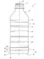
本実施形態に係るボトル1は、図1に示されるように、口部11、肩部12、胴部13及び底部14を備え、これら11〜14が、それぞれの中心軸線を共通軸上に位置させた状態で、この順に連設された概略構成となっている。Hereinafter, bottles according to embodiments of the present invention will be described with reference to the drawings.
As shown in FIG. 1, the bottle 1 according to this embodiment includes a
以下、前記共通軸をボトル軸Oといい、ボトル軸O方向に沿って口部11側を上側、底部14側を下側といい、また、ボトル軸Oに直交する方向を径方向といい、ボトル軸Oを中心に周回する方向を周方向という。
なお、ボトル1は、射出成形により有底筒状に形成されたプリフォームが、ブロー成形されて形成され、合成樹脂材料で一体に形成されている。また、口部11には、図示しないキャップが装着される。さらに、口部11、肩部12、胴部13及び底部14はそれぞれ、ボトル軸Oに直交する横断面視形状が円形状となっている。Hereinafter, the common axis is referred to as the bottle axis O, the
The bottle 1 is formed by blow-molding a preform formed into a bottomed cylinder by injection molding, and is integrally formed of a synthetic resin material. Further, a cap (not shown) is attached to the
肩部12と胴部13との接続部分には、第1環状凹溝16が全周に亘って連続して形成されている。
胴部13は筒状に形成され、ボトル軸O方向の両端部同士の間は、これら両端部より小径に形成されている。胴部13には、ボトル軸O方向に間隔をあけて複数の第2環状凹溝15が全周に亘って連続して形成されている。A first
The trunk |
胴部13と底部14との接続部分には、第3環状凹溝20が全周に亘って連続して形成されている。
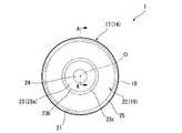
図1〜3に示すように、底部14は、上端開口部が胴部13の下端開口部に接続されたヒール部17と、ヒール部17の下端開口部を閉塞し、かつ外周縁部が接地部18とされた底壁部19と、を備えるカップ状に形成されている。
ヒール部17には、第3環状凹溝20と同じ深さの第4環状凹溝31が全周に亘って連続して形成されている。A third
As shown in FIGS. 1 to 3, the
In the
底壁部19は、図3に示すように、接地部18に径方向内側から連なり上方に向けて延びる立ち上がり周壁部21と、立ち上がり周壁部21の上端部から径方向の内側に向けて突出する環状の可動壁部22と、可動壁部22の径方向の内端部から上方に向けて延びる陥没周壁部23と、を備えている。 As shown in FIG. 3, the
立ち上がり周壁部21は、下方から上方に向かうに従い漸次縮径している。
可動壁部22は、下方に向けて突の曲面状に形成されるとともに、径方向の外側から内側に向かうに従い漸次下方に向けて延在している。この可動壁部22と立ち上がり周壁部21とは上方に向けて突の曲面部25を介して連結されている。そして、可動壁部22は、陥没周壁部23を上方に向けて移動させるように、曲面部(立ち上がり周壁部21との接続部分)25を中心に回動自在となっている。The rising
The
ここで、可動壁部22のうち、径方向に沿う外端部、すなわち曲面部25に近接した部分には、上方に向けて膨出する上方膨出部32が形成されている。この上方膨出部32は、ボトル軸O方向に沿う縦断面視で可動壁部22の法線方向に沿って突の曲面形状に形成されるとともに、周方向の全周に亘って延びる環状に形成されている。具体的に、上方膨出部32は、曲面部25における径方向の内端部と、陥没周壁部23における径方向の外端部と、を結ぶ可動壁部22の表面形状に倣って延びる仮想線L(例えば、下方に凸の曲線、又は直線)よりも上方に位置している。また、上方膨出部32の頂部は、曲面部25よりも下方に位置している。なお、上方膨出部32の径方向に沿う外端部での接線と、水平面と、のなす角度(俯角)θ1は、仮想線Lの径方向に沿う外端部での接線と、水平面と、のなす角度(俯角)θ2に対して10度以上小さく設定することが好ましい。図示の例では、θ1が28度程度、θ2が44度程度に設定されている。Here, an upper bulging
また、可動壁部22のうち、上方膨出部32よりも径方向の内側に位置する部分には、下方に向けて窪んだ下方膨出部33が形成されている。下方膨出部33は、可動壁部22の法線方向に沿って突の曲面形状に形成されるとともに、周方向の全周に亘って延びる環状に形成されている。具体的に、下方膨出部33は、上述した仮想線Lよりも下方に位置している。この場合、上述した上方膨出部32のうち、径方向の外端部は曲面部25における径方向の内端部に連設され、径方向の内端部は下方膨出部33における径方向の外端部に連設されている。 In addition, a lower bulging
なお、上方膨出部32は、上述した下方膨出部33に比べて曲率半径が小さく形成されている。また、ボトル軸O方向に沿う縦断面視において、下方膨出部33の径方向に沿う外端部から内端部までの接線に沿う長さD1は、上方膨出部32の径方向に沿う外端部から内端部までの接線に沿う長さD2よりも長く形成されている。 The upper bulging
陥没周壁部23は、ボトル軸Oと同軸に配設されるとともに、上方から下方に向かうに従い漸次拡径している。陥没周壁部23の上端部には、ボトル軸Oと同軸に配置された円板状の頂壁24が接続されており、陥没周壁部23及び頂壁24の全体で有頂筒状をなしている。なお、陥没周壁部23は、横断面視円形状に形成されている。また、陥没周壁部23は、径方向の内側に向けて突の曲面状に形成された湾曲壁部23aの上端が頂壁24に、湾曲壁部23aの下端が屈曲部23bを介して傾斜壁部23cに連接されて構成されている。傾斜壁部23cは、上方から下方に向かうに従い漸次拡径し、その下端が環状の可動壁部22の径方向における内端部に連接されている。 The depressed
そして、本実施形態では、ヒール部17のうち、接地部18に径方向の外側から連なる下ヒール部27は、該下ヒール部27に上方から連なる上ヒール部28より小径に形成されている。なお、上ヒール部28は、胴部13のボトル軸O方向両端部とともに、ボトル1の最大外径部となっている。 In the present embodiment, in the
さらに本実施形態では、下ヒール部27と上ヒール部28との連結部分29は、上方から下方に向かうに従い漸次縮径されている。また、この連結部分29の縦断面視形状は、上方から下方に向けて直線状に延在している。 Further, in the present embodiment, the connecting
このように構成されたボトル1内が減圧すると、底壁部19の曲面部25を中心にして可動壁部22が上方に向かって回動することで、可動壁部22は、陥没周壁部23を上方に向けて持ち上げるように移動する。すなわち、減圧時にボトル1の底壁部19を積極的に変形させることで、胴部13等の変形を伴うことなく、ボトル1の内圧変化(減圧)を吸収することができる。この場合、立ち上がり周壁部21と可動壁部22との接続部分を、上方に向けて突の曲面部25に形成することで、この曲面部25を中心にして可動壁部22を移動(回動)させ易くすることができる。そのため、ボトル1の内圧変化に応じて可動壁部22を柔軟に変形させることができる。 When the inside of the bottle 1 configured in this manner is depressurized, the
特に、本実施形態では、可動壁部22に上方に向けて膨出する上方膨出部32を形成することで、曲面部25を中心にして可動壁部22が移動する際に、上方膨出部32が可動壁部22の初動時の起点となる。この場合、ボトル1の内圧変化に応じて上方膨出部32が上方に移動し始めることで、これに追従して可動壁部22全体が上方に移動することになる。これにより、ボトル1の内圧変化に応じて可動壁部22全体をスムーズに移動させることができる。
したがって、可動壁部22の接線と水平面とのなす角度θ2を大きくして、減圧吸収性能の向上を図った場合であっても、可動壁部22が上方に移動し難くなるのを抑制できる。その結果、ボトル1内の減圧吸収性能の向上を図った上で、可動壁部22をスムーズに移動させることができる。In particular, in the present embodiment, by forming the upper bulging
Therefore, even when the angle θ2 formed between the tangent line of the
さらに、本実施形態では、可動壁部22のうち、上方膨出部32よりも径方向の内側に位置する部分に下方膨出部33を形成したため、可動壁部22の径方向に沿う外端部から内端部までの長さが、可動壁部22の表面形状に倣って延びる仮想線Lの長さよりも長くなる。これにより、可動壁部22の移動量を確保できるので、減圧吸収性能の更なる向上を図ることができる。 Furthermore, in this embodiment, since the lower bulging
以上、本発明の実施形態について図面を参照して詳述したが、具体的な構成はこの実施形態に限られるものではなく、本発明の要旨を逸脱しない範囲の設計変更等も含まれる。 As mentioned above, although embodiment of this invention was explained in full detail with reference to drawings, the concrete structure is not restricted to this embodiment, The design change etc. of the range which does not deviate from the summary of this invention are included.
例えば、上方膨出部32及び下方膨出部33の断面視形状は、曲面状に限らず適宜設計変更が可能である。
また、上方膨出部32及び下方膨出部33は、周方向に間欠的に形成しても構わない。
さらに、下方膨出部33は、径方向に沿って複数形成しても構わない。例えば、径方向に沿って波形に形成しても構わない。For example, the cross-sectional shape of the upper bulging
Further, the upper bulging
Further, a plurality of downward bulging
また、立ち上がり周壁部21は、例えばボトル軸O方向に沿って平行に延在させる等、適宜変更してもよい。
さらに、陥没周壁部23は、例えばボトル軸O方向に沿って平行に延在させる等、適宜変更してもよい。The rising
Further, the depressed
また、ボトル1を形成する合成樹脂材料は、例えばポリエチレンテレフタレートや、ポリエチレンナフタレート、非晶性ポリエステル等、またはこれらのブレンド材料等、適宜変更してもよい。
さらに、ボトル1は単層構造体に限らず中間層を有する積層構造体としてもよい。この中間層としては、例えばガスバリア性を有する樹脂材料からなる層、再生材からなる層、若しくは酸素吸収性を有する樹脂材料からなる層等が挙げられる。
また、前記実施形態では、肩部12、胴部13及び底部14のそれぞれのボトル軸Oに直交する横断面視形状を円形状としたが、これに限らず例えば、多角形状にする等適宜変更してもよい。The synthetic resin material forming the bottle 1 may be appropriately changed, for example, polyethylene terephthalate, polyethylene naphthalate, amorphous polyester, or a blend material thereof.
Further, the bottle 1 is not limited to a single layer structure, and may be a laminated structure having an intermediate layer. Examples of the intermediate layer include a layer made of a resin material having a gas barrier property, a layer made of a recycled material, or a layer made of a resin material having an oxygen absorbing property.
Moreover, in the said embodiment, although the cross-sectional view shape orthogonal to each bottle axis | shaft O of the
その他、本発明の趣旨を逸脱しない範囲で、前記実施形態における構成要素を周知の構成要素に置き換えることは適宜可能であり、また、前記変形例を適宜組み合わせてもよい。 In addition, it is possible to appropriately replace the constituent elements in the embodiment with known constituent elements without departing from the spirit of the present invention, and the modification examples may be combined as appropriate.
1…ボトル
14…底部
18…接地部
19…底壁部
21…立ち上がり周壁部
22…可動壁部
23…陥没周壁部
25…曲面部
32…上方膨出部
33…下方膨出部DESCRIPTION OF SYMBOLS 1 ...
Claims (2)
Translated fromJapanese底部の底壁部が、
外周縁部に位置する接地部と、
該接地部にボトル径方向の内側から連なり上方に向けて延びる立ち上がり周壁部と、
該立ち上がり周壁部の上端部からボトル径方向の内側に向けて突出する可動壁部と、
該可動壁部のボトル径方向の内端部から上方に向けて延びる陥没周壁部と、を備え、
前記可動壁部は、前記立ち上がり周壁部との接続部分を中心に前記陥没周壁部とともに上方に向けて移動自在に配設され、
前記可動壁部におけるボトル径方向に沿う外端部には、ボトル軸方向に沿う縦断面視で前記可動壁部の法線方向に沿って上方に膨出する上方膨出部が形成されていることを特徴とするボトル。A bottomed cylindrical bottle formed of a synthetic resin material,
The bottom wall of the bottom
A grounding portion located at the outer periphery,
A rising peripheral wall portion extending from the inside in the bottle radial direction to the grounding portion and extending upward;
A movable wall portion protruding from the upper end of the rising peripheral wall portion toward the inside in the bottle radial direction;
A depressed peripheral wall portion extending upward from an inner end portion in the bottle radial direction of the movable wall portion,
The movable wall portion is disposed so as to be movable upward together with the depressed peripheral wall portion around a connection portion with the rising peripheral wall portion,
An upper bulging portion that bulgesupward along the normal direction of the movable wall portion in alongitudinal sectional view along thebottle axial direction is formed at the outer end portion along the bottle radial direction of the movable wall portion. A bottle characterized by that.
Priority Applications (10)
| Application Number | Priority Date | Filing Date | Title |
|---|---|---|---|
| JP2011187491AJP5785823B2 (en) | 2011-08-30 | 2011-08-30 | Bottle |
| US14/239,557US9555927B2 (en) | 2011-08-30 | 2012-08-29 | Bottle |
| CA2847225ACA2847225C (en) | 2011-08-30 | 2012-08-29 | Bottle |
| TW101131397ATWI527740B (en) | 2011-08-30 | 2012-08-29 | Bottle |
| PCT/JP2012/071802WO2013031812A1 (en) | 2011-08-30 | 2012-08-29 | Bottle |
| CN201280041384.0ACN103764504B (en) | 2011-08-30 | 2012-08-29 | bottle |
| AU2012302797AAU2012302797B2 (en) | 2011-08-30 | 2012-08-29 | Bottle |
| KR1020147005197AKR101939714B1 (en) | 2011-08-30 | 2012-08-29 | Bottle |
| SG2014008817ASG2014008817A (en) | 2011-08-30 | 2012-08-29 | Bottle |
| EP12826802.6AEP2752369B1 (en) | 2011-08-30 | 2012-08-29 | Bottle |
Applications Claiming Priority (1)
| Application Number | Priority Date | Filing Date | Title |
|---|---|---|---|
| JP2011187491AJP5785823B2 (en) | 2011-08-30 | 2011-08-30 | Bottle |
Publications (2)
| Publication Number | Publication Date |
|---|---|
| JP2013049442A JP2013049442A (en) | 2013-03-14 |
| JP5785823B2true JP5785823B2 (en) | 2015-09-30 |
Family
ID=47756293
Family Applications (1)
| Application Number | Title | Priority Date | Filing Date |
|---|---|---|---|
| JP2011187491AActiveJP5785823B2 (en) | 2011-08-30 | 2011-08-30 | Bottle |
Country Status (10)
| Country | Link |
|---|---|
| US (1) | US9555927B2 (en) |
| EP (1) | EP2752369B1 (en) |
| JP (1) | JP5785823B2 (en) |
| KR (1) | KR101939714B1 (en) |
| CN (1) | CN103764504B (en) |
| AU (1) | AU2012302797B2 (en) |
| CA (1) | CA2847225C (en) |
| SG (1) | SG2014008817A (en) |
| TW (1) | TWI527740B (en) |
| WO (1) | WO2013031812A1 (en) |
Families Citing this family (4)
| Publication number | Priority date | Publication date | Assignee | Title |
|---|---|---|---|---|
| US10829359B2 (en) | 2018-01-08 | 2020-11-10 | Be the Change Labs, Inc. | Custom beverage creation device, system, and method |
| WO2020149832A1 (en)* | 2019-01-15 | 2020-07-23 | Amcor Rigid Packaging Usa, Llc | Vertical displacement container base |
| USD932898S1 (en)* | 2019-03-29 | 2021-10-12 | Ring Container Technologies, Llc | Container |
| USD1011908S1 (en)* | 2022-01-26 | 2024-01-23 | Pepsico, Inc. | Bottle |
Family Cites Families (14)
| Publication number | Priority date | Publication date | Assignee | Title |
|---|---|---|---|---|
| US6595380B2 (en) | 2000-07-24 | 2003-07-22 | Schmalbach-Lubeca Ag | Container base structure responsive to vacuum related forces |
| US8127955B2 (en)* | 2000-08-31 | 2012-03-06 | John Denner | Container structure for removal of vacuum pressure |
| US7150372B2 (en)* | 2003-05-23 | 2006-12-19 | Amcor Limited | Container base structure responsive to vacuum related forces |
| US8276774B2 (en)* | 2003-05-23 | 2012-10-02 | Amcor Limited | Container base structure responsive to vacuum related forces |
| US7287658B1 (en)* | 2004-01-08 | 2007-10-30 | Berry Plastics Corporation | Container having a base with a convex dome and method of use |
| US7416089B2 (en)* | 2004-12-06 | 2008-08-26 | Constar International Inc. | Hot-fill type plastic container with reinforced heel |
| TWI375641B (en)* | 2004-12-20 | 2012-11-01 | Co2 Pac Ltd | A method of processing a container and base cup structure for removal of vacuum pressure |
| JP5019810B2 (en) | 2006-07-18 | 2012-09-05 | 北海製罐株式会社 | Synthetic resin bottle and manufacturing method thereof |
| CN103057778B (en) | 2008-11-27 | 2017-04-26 | 株式会社吉野工业所 | Synthetic resin bottle |
| FR2954287B1 (en)* | 2009-12-17 | 2012-08-03 | Sidel Participations | CONTAINER WITH DEFORMABLE FLANKS |
| JP5595498B2 (en)* | 2010-06-28 | 2014-09-24 | 日精エー・エス・ビー機械株式会社 | Manufacturing method of heat-resistant container |
| JP5408501B2 (en)* | 2010-08-31 | 2014-02-05 | 株式会社吉野工業所 | Synthetic resin housing |
| WO2012129559A2 (en)* | 2011-03-24 | 2012-09-27 | Ring Container Technologies | Flexible panel to offset pressure differential |
| US9150320B2 (en)* | 2011-08-15 | 2015-10-06 | Graham Packaging Company, L.P. | Plastic containers having base configurations with up-stand walls having a plurality of rings, and systems, methods, and base molds thereof |
- 2011
- 2011-08-30JPJP2011187491Apatent/JP5785823B2/enactiveActive
- 2012
- 2012-08-29CACA2847225Apatent/CA2847225C/enactiveActive
- 2012-08-29EPEP12826802.6Apatent/EP2752369B1/enactiveActive
- 2012-08-29CNCN201280041384.0Apatent/CN103764504B/enactiveActive
- 2012-08-29TWTW101131397Apatent/TWI527740B/ennot_activeIP Right Cessation
- 2012-08-29USUS14/239,557patent/US9555927B2/enactiveActive
- 2012-08-29WOPCT/JP2012/071802patent/WO2013031812A1/enactiveApplication Filing
- 2012-08-29AUAU2012302797Apatent/AU2012302797B2/enactiveActive
- 2012-08-29KRKR1020147005197Apatent/KR101939714B1/enactiveActive
- 2012-08-29SGSG2014008817Apatent/SG2014008817A/enunknown
Also Published As
| Publication number | Publication date |
|---|---|
| WO2013031812A1 (en) | 2013-03-07 |
| AU2012302797A1 (en) | 2014-03-20 |
| TWI527740B (en) | 2016-04-01 |
| US9555927B2 (en) | 2017-01-31 |
| JP2013049442A (en) | 2013-03-14 |
| EP2752369A1 (en) | 2014-07-09 |
| EP2752369B1 (en) | 2017-01-11 |
| KR20140125344A (en) | 2014-10-28 |
| CN103764504B (en) | 2015-09-02 |
| EP2752369A4 (en) | 2015-04-29 |
| CA2847225C (en) | 2019-08-06 |
| US20140190928A1 (en) | 2014-07-10 |
| CN103764504A (en) | 2014-04-30 |
| AU2012302797B2 (en) | 2016-09-22 |
| CA2847225A1 (en) | 2013-03-07 |
| KR101939714B1 (en) | 2019-01-18 |
| TW201318933A (en) | 2013-05-16 |
| SG2014008817A (en) | 2014-04-28 |
Similar Documents
| Publication | Publication Date | Title |
|---|---|---|
| JP5501184B2 (en) | Bottle | |
| WO2012043362A1 (en) | Bottle | |
| JP6397652B2 (en) | Bottle | |
| WO2012147885A1 (en) | Bottle | |
| JP5785823B2 (en) | Bottle | |
| JP6122611B2 (en) | Bottle | |
| JP5719677B2 (en) | Bottle | |
| JP5793300B2 (en) | Bottle | |
| JP5826020B2 (en) | Bottle | |
| JP5645603B2 (en) | Bottle | |
| JP5684534B2 (en) | Bottle | |
| JP5645604B2 (en) | Bottle | |
| JP5789440B2 (en) | Bottle | |
| JP2018162087A (en) | Decompression absorption bottle | |
| JP6151881B2 (en) | Blow bottle | |
| JP5645602B2 (en) | Bottle | |
| JP2018162086A (en) | Decompression absorption bottle | |
| JP5568439B2 (en) | Bottle | |
| JP2012091827A (en) | Bottle | |
| JP5568440B2 (en) | Bottle | |
| JP2012076747A (en) | Bottle | |
| JP2012091816A (en) | Bottle |
Legal Events
| Date | Code | Title | Description |
|---|---|---|---|
| A621 | Written request for application examination | Free format text:JAPANESE INTERMEDIATE CODE: A621 Effective date:20140304 | |
| A131 | Notification of reasons for refusal | Free format text:JAPANESE INTERMEDIATE CODE: A131 Effective date:20150106 | |
| A521 | Written amendment | Free format text:JAPANESE INTERMEDIATE CODE: A523 Effective date:20150304 | |
| A131 | Notification of reasons for refusal | Free format text:JAPANESE INTERMEDIATE CODE: A131 Effective date:20150401 | |
| A521 | Written amendment | Free format text:JAPANESE INTERMEDIATE CODE: A523 Effective date:20150529 | |
| TRDD | Decision of grant or rejection written | ||
| A01 | Written decision to grant a patent or to grant a registration (utility model) | Free format text:JAPANESE INTERMEDIATE CODE: A01 Effective date:20150630 | |
| A61 | First payment of annual fees (during grant procedure) | Free format text:JAPANESE INTERMEDIATE CODE: A61 Effective date:20150727 | |
| R150 | Certificate of patent or registration of utility model | Ref document number:5785823 Country of ref document:JP Free format text:JAPANESE INTERMEDIATE CODE: R150 |