JP5783971B2 - Coating apparatus and coating method - Google Patents
Coating apparatus and coating methodDownload PDFInfo
- Publication number
- JP5783971B2 JP5783971B2JP2012178206AJP2012178206AJP5783971B2JP 5783971 B2JP5783971 B2JP 5783971B2JP 2012178206 AJP2012178206 AJP 2012178206AJP 2012178206 AJP2012178206 AJP 2012178206AJP 5783971 B2JP5783971 B2JP 5783971B2
- Authority
- JP
- Japan
- Prior art keywords
- nozzle
- solvent
- chemical
- dummy
- chemical solution
- Prior art date
- Legal status (The legal status is an assumption and is not a legal conclusion. Google has not performed a legal analysis and makes no representation as to the accuracy of the status listed.)
- Expired - Fee Related
Links
Images


Classifications
- H—ELECTRICITY
- H01—ELECTRIC ELEMENTS
- H01L—SEMICONDUCTOR DEVICES NOT COVERED BY CLASS H10
- H01L21/00—Processes or apparatus adapted for the manufacture or treatment of semiconductor or solid state devices or of parts thereof
- H01L21/02—Manufacture or treatment of semiconductor devices or of parts thereof
- H01L21/02104—Forming layers
- H01L21/02107—Forming insulating materials on a substrate
- H01L21/02225—Forming insulating materials on a substrate characterised by the process for the formation of the insulating layer
- H01L21/0226—Forming insulating materials on a substrate characterised by the process for the formation of the insulating layer formation by a deposition process
- H01L21/02282—Forming insulating materials on a substrate characterised by the process for the formation of the insulating layer formation by a deposition process liquid deposition, e.g. spin-coating, sol-gel techniques, spray coating
- H—ELECTRICITY
- H01—ELECTRIC ELEMENTS
- H01L—SEMICONDUCTOR DEVICES NOT COVERED BY CLASS H10
- H01L21/00—Processes or apparatus adapted for the manufacture or treatment of semiconductor or solid state devices or of parts thereof
- H01L21/67—Apparatus specially adapted for handling semiconductor or electric solid state devices during manufacture or treatment thereof; Apparatus specially adapted for handling wafers during manufacture or treatment of semiconductor or electric solid state devices or components ; Apparatus not specifically provided for elsewhere
- H01L21/67005—Apparatus not specifically provided for elsewhere
- H01L21/67011—Apparatus for manufacture or treatment
- H01L21/6715—Apparatus for applying a liquid, a resin, an ink or the like
Landscapes
- Engineering & Computer Science (AREA)
- Physics & Mathematics (AREA)
- Condensed Matter Physics & Semiconductors (AREA)
- General Physics & Mathematics (AREA)
- Manufacturing & Machinery (AREA)
- Computer Hardware Design (AREA)
- Microelectronics & Electronic Packaging (AREA)
- Power Engineering (AREA)
- Coating Apparatus (AREA)
- Exposure Of Semiconductors, Excluding Electron Or Ion Beam Exposure (AREA)
- Materials For Photolithography (AREA)
- Application Of Or Painting With Fluid Materials (AREA)
Description
Translated fromJapanese本発明の実施形態は、塗布装置および塗布方法に関する。 Embodiments described herein relate generally to a coating apparatus and a coating method.
ソルベントバスとダミーディスペンスポートとを有する塗布装置においては、待機時に、薬液ノズルをソルベントバス内に保持すると共に、プリウエットシンナーノズルをダミーディスペンスポート内に保持している。そして、薬液例えばレジストの塗布前または定期的に、薬液ノズルをダミーディスペンスポートへ移動させて薬液ノズルの先端からレジストを廃棄する(ダミーディスペンスを行う)ことにより、薬液ノズルの先端でレジストが固化することを防止し、ウエハ上に異物が付くことを防止している。 In a coating apparatus having a solvent bath and a dummy dispense port, the chemical nozzle is held in the solvent bath and the pre-wet thinner nozzle is held in the dummy dispense port during standby. Then, before applying the chemical solution, for example, the resist, or periodically, the chemical solution nozzle is moved to the dummy dispensing port and the resist is discarded from the tip of the chemical solution nozzle (dummy dispensing is performed), so that the resist is solidified at the tip of the chemical solution nozzle. This prevents foreign matter from adhering to the wafer.
ところで、プリウエットシンナーノズルの先端に異物が付着していることがあり、この異物が付着したプリウエットシンナーノズルでプリウエットを行うと、異物がウエハ上に付いてウエハを汚染してしまうことがあった。ウエハが汚染されると、半導体製造において、歩留まりが悪化したり、リワークが発生したりして生産効率を劣化させるという問題があった。 By the way, foreign matter may adhere to the tip of the prewetting thinner nozzle. When prewetting is performed with the prewetting thinner nozzle to which the foreign matter has adhered, the foreign matter may adhere to the wafer and contaminate the wafer. there were. When the wafer is contaminated, there has been a problem in that the production efficiency is deteriorated due to deterioration in yield or rework in semiconductor manufacturing.
そこで、プリウエットシンナーノズルによる基板のプリウエットを行うときに、異物が基板を汚染することを防止できる塗布装置および塗布方法を提供する。 Accordingly, a coating apparatus and a coating method are provided that can prevent foreign matters from contaminating the substrate when the substrate is pre-wet by a pre-wetting thinner nozzle.
本実施形態の塗布装置は、基板上に薬液を塗布する塗布装置であって、前記基板上に薬液を吐出する薬液ノズルと、前記基板上に溶剤を吐出する溶剤ノズルとを備える。そして、溶剤が収容されるものであって、前記薬液ノズルの待機時に前記薬液ノズルの先端が前記溶剤蒸気中に保持されるソルベントバスと、前記薬液ノズルのダミーディスペンス時に前記薬液を廃棄するためのものであって、前記溶剤ノズルの待機時に前記溶剤ノズルが収容されるダミーディスペンスポートとを備える。更に、前記ダミーディスペンスポート周辺の雰囲気をイオン化するイオン化装置を備える。 The coating apparatus according to the present embodiment is a coating apparatus that applies a chemical solution onto a substrate, and includes a chemical nozzle that discharges a chemical solution onto the substrate and a solvent nozzle that discharges a solvent onto the substrate. A solvent is contained, and a solvent bath in which a tip of the chemical nozzle is held in the solvent vapor when the chemical nozzle is waiting, and for discarding the chemical at the time of dummy dispensing of the chemical nozzle And a dummy dispense port in which the solvent nozzle is accommodated during standby of the solvent nozzle. Furthermore, an ionization device for ionizing the atmosphere around the dummy dispense port is provided.
本実施形態の塗布方法は、基板上に薬液を吐出する薬液ノズルと、前記基板上に溶剤を吐出する溶剤ノズルと、溶剤が収容されるものであって、前記薬液ノズルの待機時に前記薬液ノズルの先端が前記溶剤蒸気中に保持されるソルベントバスと、前記溶剤ノズルの待機時に前記溶剤ノズルが収容されるダミーディスペンスポートとを備えた塗布装置によって前記基板上に薬液を塗布する塗布方法であって、前記薬液ノズルを前記ダミーディスペンスポート上に移動させて前記薬液ノズルから前記ダミーディスペンスポートに薬液を廃棄するダミーディスペンスを実行する際、ダミーディスペンスの実行前までに前記ダミーディスペンスポート周辺の雰囲気をイオン化しておくようにした。 The coating method according to the present embodiment includes a chemical nozzle that discharges a chemical onto a substrate, a solvent nozzle that discharges a solvent onto the substrate, and a solvent that is contained in the chemical nozzle when the chemical nozzle is on standby. The coating method includes applying a chemical solution onto the substrate by a coating apparatus including a solvent bath in which a tip of the solvent is held in the solvent vapor and a dummy dispense port in which the solvent nozzle is accommodated when the solvent nozzle is on standby. Then, when performing a dummy dispense that moves the chemical solution nozzle onto the dummy dispense port and discards the chemical solution from the chemical solution nozzle to the dummy dispense port, the atmosphere around the dummy dispense port is changed before the dummy dispense is executed. I was allowed to ionize.
以下、複数の実施形態について、図面を参照して説明する。尚、各実施形態において、実質的に同一の構成部位には同一の符号を付し、説明を省略する。但し、図面は模式的なものであり、厚みと平面寸法との関係、各層の厚みの比率等は現実のものとは異なる。 Hereinafter, a plurality of embodiments will be described with reference to the drawings. In each embodiment, substantially the same components are assigned the same reference numerals, and description thereof is omitted. However, the drawings are schematic, and the relationship between the thickness and the planar dimensions, the ratio of the thickness of each layer, and the like are different from the actual ones.
(第1実施形態)
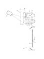
図1ないし図3は、第1実施形態を示す。図1は、本実施形態のコーター装置(塗布装置)の概略構成を示す縦断側面図である。図2は、本実施形態のコーター装置(塗布装置)の概略構成を示す上面図である。図1に示すように、コーター装置1は、コーターカップ2を備え、このコーターカップ2内には、ウエハ(半導体基板)Wを載置支持するスピンチャック3が回転可能に配設されている。ウエハWはスピンチャック3上に載置されて真空吸着により固定される。上記コーターカップ2内には、いずれも図示しないエッジカットノズルおよびバックサイドリンスノズルが配設され、これらノズルからリンス液がウエハ3の所定の領域に供給される。(First embodiment)
1 to 3 show a first embodiment. FIG. 1 is a longitudinal side view showing a schematic configuration of a coater device (coating device) of the present embodiment. FIG. 2 is a top view showing a schematic configuration of the coater device (coating device) of the present embodiment. As shown in FIG. 1, the
コーターカップ2の外側には、溶剤が収容されたソルベントバス4と、塗布液を廃棄するダミーディスペンスポート5とが並べて配設される。図2に示すように、ソルベントバス4およびダミーディスペンスポート5は、図2中上下方向に長い形状の槽で構成されており、上面部が開口している。 On the outside of the
薬液例えばレジストをウエハW上に供給するレジストノズル(薬液ノズル)6は、待機時には、ソルベントバス4内に収容されている。この場合、レジストノズル6の基端部(図1中の上端部)には矩形状の取付部材7が設けられており、この取付部材7の下面の両端部をソルベントバス4の上端部に載置している(図1及び図2参照)。レジストノズル6の取付部材7は、ロボットアーム(図示しない)の先端部のハンド部8の下面部のノズル取付部8aに着脱可能に取り付けられる構成となっている。ハンド部8は、ロボットアームにより例えばXYZ方向に移動可能である。 A resist nozzle (chemical solution nozzle) 6 for supplying a chemical solution, for example, a resist onto the wafer W is accommodated in the
そして、上記ハンド部8の下面部の図1中の左端部には、プリウエットシンナーノズル(溶剤ノズル)9の基端部が取り付けられている。図1に示すように、待機時には、レジストノズル6がソルベントバス4内に収容されると共に、プリウエットシンナーノズル9がダミーディスペンスポート5内に収容される。この場合、ソルベントバス4内には溶剤が収容されていることから、レジストノズル6の待機時には該レジストノズル6の先端が溶剤蒸気中に保持されている。また、プリウエットシンナーノズル9の待機時に、該プリウエットシンナーノズル9の先端がダミーディスペンスポート5内に収容されていることから、プリウエットシンナーノズル9から溶剤をダミーディスペンスする必要がある場合には、上記待機時の状態で溶剤のダミーディスペンスを実行する。 A base end portion of a pre-wet thinner nozzle (solvent nozzle) 9 is attached to the left end portion of the lower surface portion of the
尚、図2に示すように、レジストノズル6の他に、他の薬液を吐出するための薬液ノズル10が複数用意されており、これら複数の薬液ノズル10は待機時にソルベントバス4内に収容されている(図2中2点鎖線参照)。上記複数の薬液ノズル10の基端部には矩形状の取付部材7が設けられており、この取付部材7の下面の両端部をソルベントバス4の上端部に載置している。各薬液ノズル10の取付部材7は、ロボットアームのハンド部8の下面部のノズル取付部8aに着脱可能に取り付けられる構成となっている。即ち、上記ハンド部8によって、レジストノズル6及び複数の薬液ノズル10の中から1つのノズルを任意に選択して取り付けることが可能な構成となっている。 As shown in FIG. 2, in addition to the
また、図1に示すように、ソルベントバス4およびダミーディスペンスポート5の上方には、軟X線照射型イオナイザ(イオン化装置)11が配設されている。この軟X線照射型イオナイザ11は、図1中破線で示すように、軟X線照射を照射して、ダミーディスペンスポート5周辺の空気(雰囲気)をイオン化する機能を有する。この空気のイオン化により、ダミーディスペンスポート5及びその周辺が静電気を帯びていたとしても、その静電気を中和(除電)することができる構成となっている。 As shown in FIG. 1, a soft X-ray irradiation ionizer (ionizer) 11 is disposed above the
次に、上記した構成のコーター装置1の動作について、図3も参照して説明する。まず、待機状態では、図1に示すように、レジストノズル6および複数の薬液ノズル10がソルベントバス4内に収容されていると共に、プリウエットシンナーノズル9がダミーディスペンスポート5内に収容されている。そして、これからレジストの塗布を実行する場合には、ロボットアームのハンド部8の下面部のノズル取付部8aに、レジストノズル6が取り付けられている。 Next, the operation of the
上記コーター装置1によってレジスト塗布を実行する場合、レジストの塗布前、または、定期的に、レジストノズル6のダミーディスペンスを行う。この場合、上記待機状態からハンド部8を上昇させ、更に横方向に移動させることにより、図3に示すように、ダミーディスペンスポート5の上方にレジストノズル6を位置させる。ここで、ダミーディスペンスの実行前に、軟X線照射型イオナイザ11を駆動することにより、図1中破線で示すように、軟X線照射を照射して、ダミーディスペンスポート5、レジストノズル6およびハンド部8の周辺の空気をイオン化する。即ち、ダミーディスペンスの実行前までに、ダミーディスペンスポート5周辺の空気をイオン化しておくようにする。上記空気のイオン化により、ダミーディスペンスポート5及びその周辺が静電気を帯びていたとしても、その静電気を中和(除電)することができる。 When the resist coating is performed by the
そして、ダミーディスペンスポート5周辺の空気をイオン化した状態で、レジストノズル6の先端からレジスト13(図13参照)を吐出(ダミーディスペンス)してレジスト13をダミーディスペンスポート5に廃棄する。ここで、吐出されたレジスト13が例えばプラス(またはマイナス)の静電気を帯びた状態であった場合、レジスト13の表面の電荷により、近傍に浮遊する反対の極性のマイナスイオン(またはプラスイオン)が引き寄せられて中和される。即ち、レジストノズル6から吐出されたレジスト13から静電気が上記イオンにより除去される。 Then, in a state where the air around the
この結果、レジストノズル6から吐出されたレジスト13は、図3に示すように、鉛直下方向に落下していくことから、ダミーディスペンスポート5の内周壁部にレジスト(異物)が付着することを確実に防止できる。これによって、待機時において、プリウエットシンナーノズル9がダミーディスペンスポート5内に収容されたときに、プリウエットシンナーノズル9の先端に異物が付着することを防止できる。 As a result, the
尚、ダミーディスペンスポート5、レジストノズル6およびハンド部8等に静電気が帯電していたとしても、上記軟X線照射型イオナイザ11によって発生したイオンによって上記各部材等に帯電した静電気を除去することができる。 Even if the static electricity is charged in the dummy dispensing
ちなみに、レジストノズル6からレジスト13が静電気を帯びた状態のまま吐出されたときには、静電気を帯びたレジスト13の吐出(落下)方向が、ダミーディスペンスポート5の内周壁部に近付く方向に曲がり、その結果、ダミーディスペンスポート5の内周壁部にレジスト(異物)が付着してしまう。このような場合には、待機時において、プリウエットシンナーノズル9がダミーディスペンスポート5内に収容されたときに、ダミーディスペンスポート5の内周壁部に付着していた異物がプリウエットシンナーノズル9の先端に付着してしまい、この異物が付着したプリウエットシンナーノズル9でウエハWのプリウエットを行うと、異物がウエハW上に付いて汚染してしまうという問題があった。これに対して、本実施形態によれば、このような問題を確実に解消することができる。 Incidentally, when the resist 13 is discharged from the resist
尚、上記実施形態では、軟X線照射型イオナイザ11による軟X線の照射を、レジストノズル6からレジスト13をダミーディスペンスするダミーディスペンス実行の前の時点からダミーディスペンス実行終了の時点まで行うように構成したが、これに限られるものではなく、ダミーディスペンス実行のある程度前から、例えばダミーディスペンスのためにレジストノズル6(ハンド部8)の移動を開始した時点や、上記移動開始時点からレジストノズル6(ハンド部8)をダミーディスペンスポート5の上方に位置させる前までの移動中の時点等から軟X線の照射を開始するように構成しても良い。 In the above-described embodiment, the soft X-ray irradiation by the soft
(第2実施形態)
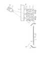
図4は、第2実施形態を示すものである。尚、第1実施形態と同一構成には、同一符号を付している。この第2実施形態では、図4に示すように、軟X線照射型イオナイザ11によって、ダミーディスペンスポート5周辺の他に、コーターカップ2、ウエハWおよびスピンチャック3等周辺にも軟X線を照射するように構成した。(Second Embodiment)
FIG. 4 shows a second embodiment. In addition, the same code | symbol is attached | subjected to the same structure as 1st Embodiment. In the second embodiment, as shown in FIG. 4, the soft
上述した以外の第2実施形態の構成は、第1実施形態と同じ構成となっている。従って、第2実施形態においても、第1実施形態とほぼ同じ作用効果を得ることができる。特に、第2実施形態によれば、ダミーディスペンスポート5周辺の他に、コーターカップ2、ウエハWおよびスピンチャック3等周辺にも軟X線を照射してそれら周辺の空気(雰囲気)をイオン化するように構成したので、コーターカップ2、ウエハWおよびスピンチャック3等に帯電した静電気を除去(中和)することができる。 The configuration of the second embodiment other than that described above is the same as that of the first embodiment. Therefore, in the second embodiment, substantially the same operational effects as in the first embodiment can be obtained. In particular, according to the second embodiment, in addition to the periphery of the dummy dispense
(第3実施形態)
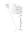
図5は、第3実施形態を示すものである。尚、第2実施形態と同一構成には、同一符号を付している。この第3実施形態では、図5に示すように、複数の軟X線照射型イオナイザ11を設け、これら複数の軟X線照射型イオナイザ11によって、ダミーディスペンスポート5、コーターカップ2、ウエハWおよびスピンチャック3等周辺に軟X線を照射するように構成した。(Third embodiment)
FIG. 5 shows a third embodiment. In addition, the same code | symbol is attached | subjected to the same structure as 2nd Embodiment. In the third embodiment, as shown in FIG. 5, a plurality of soft X-ray
上述した以外の第3実施形態の構成は、第2実施形態と同じ構成となっている。従って、第3実施形態においても、第2実施形態とほぼ同じ作用効果を得ることができる。特に、第3実施形態によれば、複数の軟X線照射型イオナイザ11によって、ダミーディスペンスポート5、コーターカップ2、ウエハWおよびスピンチャック3等周辺に軟X線を照射してそれら周辺の空気(雰囲気)をイオン化するように構成したので、ダミーディスペンスポート5、コーターカップ2、ウエハWおよびスピンチャック3等に帯電した静電気をより一層確実に除去することができる。 The configuration of the third embodiment other than that described above is the same as that of the second embodiment. Therefore, in the third embodiment, substantially the same operational effects as in the second embodiment can be obtained. In particular, according to the third embodiment, a plurality of soft
(第4実施形態)
図6は、第4実施形態を示すものである。尚、第1実施形態と同一構成には、同一符号を付している。この第4実施形態では、図6に示すように、軟X線照射型イオナイザ11に代えてコロナ放電型イオナイザ12を設け、このコロナ放電型イオナイザ12は送風機12aを内蔵する。この構成においては、コロナ放電型イオナイザ12の放電電極(図示しない)によってコロナ放電を発生させ、このコロナ放電により放電電極周辺の空気をイオン化する。そして、コロナ放電型イオナイザ12の送風機12aによって上記イオン化した空気をダミーディスペンスポート5周辺に吹き付けるように構成した。上述した以外の第4実施形態の構成は、第1実施形態と同じ構成となっている。従って、第4実施形態においても、第1実施形態とほぼ同じ作用効果を得ることができる。(Fourth embodiment)
FIG. 6 shows a fourth embodiment. In addition, the same code | symbol is attached | subjected to the same structure as 1st Embodiment. In the fourth embodiment, as shown in FIG. 6, a
(第5実施形態)
図7は、第5実施形態を示すものである。尚、第4実施形態と同一構成には、同一符号を付している。この第5実施形態では、図7に示すように、コロナ放電型イオナイザ12によって、ダミーディスペンスポート5周辺の他に、コーターカップ2、ウエハWおよびスピンチャック3等周辺にもイオン化した空気を吹き付けるように構成した。(Fifth embodiment)
FIG. 7 shows a fifth embodiment. In addition, the same code | symbol is attached | subjected to the same structure as 4th Embodiment. In the fifth embodiment, as shown in FIG. 7, the
上述した以外の第5実施形態の構成は、第4実施形態と同じ構成となっている。従って、第5実施形態においても、第4実施形態とほぼ同じ作用効果を得ることができる。特に、第5実施形態によれば、ダミーディスペンスポート5周辺の他に、コーターカップ2、ウエハWおよびスピンチャック3等周辺にもイオン化した空気を吹き付けるように構成したので、コーターカップ2、ウエハWおよびスピンチャック3等に帯電した静電気を除去することができる。 The configuration of the fifth embodiment other than that described above is the same as that of the fourth embodiment. Accordingly, in the fifth embodiment, substantially the same operational effects as in the fourth embodiment can be obtained. In particular, according to the fifth embodiment, since the ionized air is blown to the periphery of the
(第6実施形態)
図8は、第6実施形態を示すものである。尚、第5実施形態と同一構成には、同一符号を付している。この第6実施形態では、図8に示すように、複数のコロナ放電型イオナイザ12を設け、これら複数のコロナ放電型イオナイザ12によって、ダミーディスペンスポート5、コーターカップ2、ウエハWおよびスピンチャック3等周辺にイオン化した空気を吹き付けるように構成した。(Sixth embodiment)
FIG. 8 shows a sixth embodiment. In addition, the same code | symbol is attached | subjected to the same structure as 5th Embodiment. In the sixth embodiment, as shown in FIG. 8, a plurality of
上述した以外の第6実施形態の構成は、第5実施形態と同じ構成となっている。従って、第6実施形態においても、第5実施形態とほぼ同じ作用効果を得ることができる。特に、第6実施形態によれば、複数のコロナ放電型イオナイザ12によって、ダミーディスペンスポート5、コーターカップ2、ウエハWおよびスピンチャック3等周辺にイオン化した空気を吹き付けるように構成したので、ダミーディスペンスポート5、コーターカップ2、ウエハWおよびスピンチャック3等に帯電した静電気をより一層確実に除去することができる。 The configuration of the sixth embodiment other than that described above is the same as that of the fifth embodiment. Therefore, in the sixth embodiment, substantially the same operational effects as in the fifth embodiment can be obtained. In particular, according to the sixth embodiment, since a plurality of
(その他の実施形態)
以上説明した複数の実施形態に加えて以下のような構成を採用しても良い。
上記した各実施形態では、レジストノズル6からレジスト13をダミーディスペンスする際に、軟X線照射型イオナイザ11またはコロナ放電型イオナイザ12を駆動して上記レジスト13等に帯電した静電気を除去する構成に適用したが、これに限られるものではなく、他の薬液ノズル10から他の薬液(例えばSOG(Spin On Glass)膜形成用の薬液(液状のシリカ系化合物)や、ポリシラザン溶液等)をダミーディスペンスする際に、軟X線照射型イオナイザ11またはコロナ放電型イオナイザ12を駆動して上記薬液等に帯電した静電気を除去する構成に適用しても良い。(Other embodiments)
In addition to the plurality of embodiments described above, the following configurations may be adopted.
In each of the above-described embodiments, when the resist 13 is dummy-dispensed from the resist
また、上記各実施形態では、軟X線照射型イオナイザ11またはコロナ放電型イオナイザ12を駆動して、ダミーディスペンスポート5周辺、または、ダミーディスペンスポート5、コーターカップ2、ウエハWおよびスピンチャック3等周辺の空気をイオン化するように構成したが、これに限られるものではなく、ダミーディスペンスポート5、コーターカップ2、ウエハW、スピンチャック3およびソルベントバス4等周辺の空気をイオン化するように構成しても良い。 Further, in each of the above embodiments, the soft
また、上記各実施形態では、イオナイザとして軟X線照射型イオナイザ11またはコロナ放電型イオナイザ12を用いるように構成したが、他のイオナイザを用いるように構成しても良い。 In each of the above embodiments, the soft X-ray
以上のように、本実施形態によると、ダミーディスペンスポート周辺の空気をイオン化するイオン化装置を備えたので、薬液ノズルのダミーディスペンスを行うときに、薬液ノズルから吐出された薬液がダミーディスペンスポートの内周壁部に付着することを防止できる。この結果、プリウエットシンナーノズルの先端に異物が付着して、ウエハをプリウエットする際にウエハが異物で汚染されてしまうことを防止できる。 As described above, according to the present embodiment, since the ionization device that ionizes the air around the dummy dispense port is provided, the chemical solution discharged from the chemical solution nozzle is contained in the dummy dispense port when performing the dummy dispense of the chemical solution nozzle. It can prevent adhering to a surrounding wall part. As a result, it is possible to prevent foreign matter from adhering to the tip of the prewetting thinner nozzle and contaminating the wafer with foreign matter when prewetting the wafer.
本発明のいくつかの実施形態を説明したが、これらの実施形態は、例として提示したものであり、発明の範囲を限定することは意図していない。これら新規な実施形態は、その他の様々な形態で実施されることが可能であり、発明の要旨を逸脱しない範囲で、種々の省略、置き換え、変更を行うことができる。これら実施形態やその変形は、発明の範囲や要旨に含まれるとともに、特許請求の範囲に記載された発明とその均等の範囲に含まれる。 Although several embodiments of the present invention have been described, these embodiments are presented by way of example and are not intended to limit the scope of the invention. These novel embodiments can be implemented in various other forms, and various omissions, replacements, and changes can be made without departing from the scope of the invention. These embodiments and modifications thereof are included in the scope and gist of the invention, and are included in the invention described in the claims and the equivalents thereof.
図面中、1はコーター装置(塗布装置)、2はコーターカップ、3はウエハ(半導体基板)、4はソルベントバス、5はダミーディスペンスポート、6はレジストノズル(薬液ノズル)、9はプリウエットシンナーノズル(溶剤ノズル)、10は薬液ノズル、11は軟X線照射型イオナイザ(イオン化装置)、12はコロナ放電型イオナイザ(イオン化装置)、13はレジスト(薬液)である。 In the drawings, 1 is a coater device (coating device), 2 is a coater cup, 3 is a wafer (semiconductor substrate), 4 is a solvent bath, 5 is a dummy dispense port, 6 is a resist nozzle (chemical solution nozzle), and 9 is a pre-wet thinner. Nozzles (solvent nozzles), 10 is a chemical solution nozzle, 11 is a soft X-ray irradiation type ionizer (ionization device), 12 is a corona discharge type ionizer (ionization device), and 13 is a resist (chemical solution).
Claims (5)
Translated fromJapanese前記基板上に薬液を吐出する薬液ノズルと、
前記基板上に溶剤を吐出する溶剤ノズルと、
溶剤が収容されるものであって、前記薬液ノズルの待機時に前記薬液ノズルの先端が前記溶剤蒸気中に保持されるソルベントバスと、
前記薬液ノズルのダミーディスペンス時に前記薬液を廃棄するためのものであって、前記溶剤ノズルの待機時に前記溶剤ノズルが収容されるダミーディスペンスポートと、
前記ダミーディスペンスポート周辺および前記基板周辺の雰囲気をイオン化するイオン化装置とを備えた塗布装置。An application device for applying a chemical solution on a substrate,
A chemical nozzle for discharging the chemical on the substrate;
A solvent nozzle for discharging the solvent onto the substrate;
A solvent is contained, and a solvent bath in which a tip of the chemical liquid nozzle is held in the solvent vapor during standby of the chemical liquid nozzle;
A dummy dispensing port for discarding the chemical solution during dummy dispensing of the chemical solution nozzle, in which the solvent nozzle is accommodated during standby of the solvent nozzle;
A coating apparatus comprising: an ionization device that ionizes an atmosphere around the dummy dispense port and around the substrate.
前記基板上に薬液を吐出する薬液ノズルと、
前記基板上に溶剤を吐出する溶剤ノズルと、
溶剤が収容されるものであって、前記薬液ノズルの待機時に前記薬液ノズルの先端が前記溶剤蒸気中に保持されるソルベントバスと、
前記薬液ノズルのダミーディスペンス時に前記薬液を廃棄するためのものであって、前記溶剤ノズルの待機時に前記溶剤ノズルが収容されるダミーディスペンスポートと、
前記ダミーディスペンスポート周辺の雰囲気をイオン化するイオン化装置とを備えた塗布装置。An application device for applying a chemical solution on a substrate,
A chemical nozzle for discharging the chemical on the substrate;
A solvent nozzle for discharging the solvent onto the substrate;
A solvent is contained, and a solvent bath in which a tip of the chemical liquid nozzle is held in the solvent vapor during standby of the chemical liquid nozzle;
A dummy dispensing port for discarding the chemical solution during dummy dispensing of the chemical solution nozzle, in which the solvent nozzle is accommodated during standby of the solvent nozzle;
A coating apparatus comprising: an ionizer that ionizes an atmosphere around the dummy dispense port.
前記薬液ノズルを前記ダミーディスペンスポート上に移動させて前記薬液ノズルから前記ダミーディスペンスポートに薬液を廃棄するダミーディスペンスを実行する際、ダミーディスペンスの実行前までに前記ダミーディスペンスポート周辺の雰囲気をイオン化しておくようにしたことを特徴とする塗布方法。
A chemical nozzle that discharges a chemical solution onto a substrate, a solvent nozzle that discharges a solvent onto the substrate, and a solvent are accommodated, and the tip of the chemical nozzle is placed in the solvent vapor during standby of the chemical solution nozzle A coating method for applying a chemical solution on the substrate by a coating apparatus including a solvent bath to be held and a dummy dispensing port in which the solvent nozzle is accommodated when waiting for the solvent nozzle,
When performing a dummy dispense that moves the chemical solution nozzle onto the dummy dispense port and discards the chemical solution from the chemical solution nozzle to the dummy dispense port, the atmosphere around the dummy dispense port is ionized before the dummy dispense is executed. An application method characterized in that it is prepared in advance.
Priority Applications (2)
| Application Number | Priority Date | Filing Date | Title |
|---|---|---|---|
| JP2012178206AJP5783971B2 (en) | 2012-08-10 | 2012-08-10 | Coating apparatus and coating method |
| US13/763,001US20140045344A1 (en) | 2012-08-10 | 2013-02-08 | Coater apparatus and coating method |
Applications Claiming Priority (1)
| Application Number | Priority Date | Filing Date | Title |
|---|---|---|---|
| JP2012178206AJP5783971B2 (en) | 2012-08-10 | 2012-08-10 | Coating apparatus and coating method |
Publications (2)
| Publication Number | Publication Date |
|---|---|
| JP2014036198A JP2014036198A (en) | 2014-02-24 |
| JP5783971B2true JP5783971B2 (en) | 2015-09-24 |
Family
ID=50066518
Family Applications (1)
| Application Number | Title | Priority Date | Filing Date |
|---|---|---|---|
| JP2012178206AExpired - Fee RelatedJP5783971B2 (en) | 2012-08-10 | 2012-08-10 | Coating apparatus and coating method |
Country Status (2)
| Country | Link |
|---|---|
| US (1) | US20140045344A1 (en) |
| JP (1) | JP5783971B2 (en) |
Families Citing this family (7)
| Publication number | Priority date | Publication date | Assignee | Title |
|---|---|---|---|---|
| JP6378890B2 (en)* | 2013-03-01 | 2018-08-22 | 株式会社荏原製作所 | Substrate processing method |
| US9855579B2 (en)* | 2014-02-12 | 2018-01-02 | Taiwan Semiconductor Manufacturing Company | Spin dispenser module substrate surface protection system |
| JP6407829B2 (en)* | 2015-09-30 | 2018-10-17 | 東京エレクトロン株式会社 | Substrate liquid processing apparatus and substrate liquid processing method |
| JP6365620B2 (en)* | 2016-10-17 | 2018-08-01 | 大日本印刷株式会社 | Imprint method and imprint apparatus |
| JP6365619B2 (en)* | 2016-10-17 | 2018-08-01 | 大日本印刷株式会社 | Imprint method and imprint apparatus |
| JP7175122B2 (en)* | 2018-08-02 | 2022-11-18 | 東京エレクトロン株式会社 | SUBSTRATE PROCESSING APPARATUS AND SUBSTRATE PROCESSING METHOD |
| US12287195B2 (en)* | 2021-11-05 | 2025-04-29 | Nanya Technology Corporation | Coater cup deformation testing device and method of coater cup deformation testing |
Family Cites Families (35)
| Publication number | Priority date | Publication date | Assignee | Title |
|---|---|---|---|---|
| JPS5284976A (en)* | 1976-01-07 | 1977-07-14 | Hitachi Ltd | Contamination preventing method for sensitive corrosion-resistant resi ns |
| JPH0457280A (en)* | 1990-06-22 | 1992-02-25 | Nec Corp | Magnetic disk device |
| JPH06120132A (en)* | 1992-10-02 | 1994-04-28 | Tokyo Electron Ltd | Resist coater |
| TW339415B (en)* | 1994-04-28 | 1998-09-01 | Chisso Corp | Processing and manufacturing method of LCD elements |
| JP3227642B2 (en)* | 1995-10-13 | 2001-11-12 | 東京エレクトロン株式会社 | Coating device |
| JPH1076213A (en)* | 1996-09-03 | 1998-03-24 | Tokyo Electron Ltd | Method and apparatus for coating |
| US5938847A (en)* | 1996-09-03 | 1999-08-17 | Tokyo Electron Limited | Method and apparatus for coating a film on an object being processed |
| JP3223142B2 (en)* | 1997-08-22 | 2001-10-29 | チッソ株式会社 | Manufacturing method of liquid crystal display element |
| US6170494B1 (en)* | 1999-11-12 | 2001-01-09 | Advanced Micro Devices, Inc. | Method for automatically cleaning resist nozzle |
| US6514344B2 (en)* | 1999-12-16 | 2003-02-04 | Tokyo Electron Limited | Film forming unit |
| US6878401B2 (en)* | 2001-09-27 | 2005-04-12 | Tokyo Electron Limited | Substrate processing method |
| JP3708880B2 (en)* | 2002-01-22 | 2005-10-19 | 東京エレクトロン株式会社 | Substrate processing method and substrate processing apparatus |
| JP3760131B2 (en)* | 2002-01-22 | 2006-03-29 | 東京エレクトロン株式会社 | Processing method |
| KR100877472B1 (en)* | 2002-01-22 | 2009-01-07 | 도쿄엘렉트론가부시키가이샤 | Substrate processing method and substrate processing apparatus |
| JP4234930B2 (en)* | 2002-01-24 | 2009-03-04 | セイコーエプソン株式会社 | Film forming apparatus and film forming method |
| AU2003277594A1 (en)* | 2002-11-18 | 2004-06-15 | Tokyo Electron Limited | Insulation film formation device |
| JP4030860B2 (en)* | 2002-11-18 | 2008-01-09 | 東京エレクトロン株式会社 | Insulating film forming equipment |
| KR100935281B1 (en)* | 2003-03-06 | 2010-01-06 | 도쿄엘렉트론가부시키가이샤 | Treatment liquid supply nozzle and treatment liquid supply device |
| WO2005014289A1 (en)* | 2003-08-08 | 2005-02-17 | Konica Minolta Holdings, Inc. | Liquid jetting device, liquid jetting method, and method of forming wiring pattern on circuit board |
| JP4878796B2 (en)* | 2004-09-06 | 2012-02-15 | 富士フイルム株式会社 | Manufacturing method of optical film |
| JP4216238B2 (en)* | 2004-09-24 | 2009-01-28 | 東京エレクトロン株式会社 | Coating processing apparatus and coating processing method |
| KR100611060B1 (en)* | 2004-12-07 | 2006-08-09 | 삼성전자주식회사 | Device for supplying a solution onto a substrate |
| JP4606234B2 (en)* | 2005-04-15 | 2011-01-05 | 東京エレクトロン株式会社 | Liquid processing method and liquid processing apparatus |
| JP2007214347A (en)* | 2006-02-09 | 2007-08-23 | Matsushita Electric Ind Co Ltd | Electronic device cleaning apparatus and electronic device cleaning method |
| JP4621613B2 (en)* | 2006-03-09 | 2011-01-26 | 株式会社東芝 | Manufacturing method of semiconductor device |
| KR100941075B1 (en)* | 2007-12-27 | 2010-02-09 | 세메스 주식회사 | Processing liquid supply unit, substrate processing apparatus and method using same |
| JP4718584B2 (en)* | 2008-07-01 | 2011-07-06 | ヤスハラケミカル株式会社 | Treatment liquid for dissolving polysilazane and method for manufacturing semiconductor device using the same |
| JP5369538B2 (en)* | 2008-08-12 | 2013-12-18 | 東京エレクトロン株式会社 | Liquid processing apparatus, liquid processing method, and storage medium |
| JP5295829B2 (en)* | 2009-03-12 | 2013-09-18 | 東京エレクトロン株式会社 | Substrate cleaning method |
| JP5336949B2 (en)* | 2009-06-30 | 2013-11-06 | サントリーホールディングス株式会社 | Resin container charge removal method, resin container sterilization filling method, resin container filling capping method, resin container charge removal device and resin container sterilization filling system |
| JP5485056B2 (en)* | 2010-07-21 | 2014-05-07 | 東京エレクトロン株式会社 | Ion supply apparatus and processing system for target object provided with the same |
| JP5336441B2 (en)* | 2010-08-24 | 2013-11-06 | 東京エレクトロン株式会社 | Liquid processing apparatus and liquid processing method |
| JP5251941B2 (en)* | 2010-09-01 | 2013-07-31 | 東京エレクトロン株式会社 | Liquid processing apparatus, liquid processing method, and storage medium |
| WO2012056911A1 (en)* | 2010-10-29 | 2012-05-03 | 大日本印刷株式会社 | Method and apparatus for washing mold for imprinting applications, and process for producing mold for imprinting applications |
| JP5813495B2 (en)* | 2011-04-15 | 2015-11-17 | 東京エレクトロン株式会社 | Liquid processing method, liquid processing apparatus, and storage medium |
- 2012
- 2012-08-10JPJP2012178206Apatent/JP5783971B2/ennot_activeExpired - Fee Related
- 2013
- 2013-02-08USUS13/763,001patent/US20140045344A1/ennot_activeAbandoned
Also Published As
| Publication number | Publication date |
|---|---|
| US20140045344A1 (en) | 2014-02-13 |
| JP2014036198A (en) | 2014-02-24 |
Similar Documents
| Publication | Publication Date | Title |
|---|---|---|
| JP5783971B2 (en) | Coating apparatus and coating method | |
| CN108604535B (en) | Developing unit, substrate processing apparatus, developing method, and substrate processing method | |
| TWI637451B (en) | Semiconductor apparatus and washing method | |
| US10639665B2 (en) | Substrate processing apparatus and standby method for ejection head | |
| TWI759725B (en) | Substrate processing method, semiconductor manufacturing method, and substrate processing apparatus | |
| TWI576657B (en) | Photomask cleaning apparatus and method | |
| US11114302B2 (en) | Substrate processing apparatus and substrate processing method | |
| JP7142323B2 (en) | Element chip manufacturing method | |
| JP2003080144A (en) | Coating film forming apparatus | |
| US10773425B2 (en) | Imprint template manufacturing apparatus and imprint template manufacturing method | |
| US20170110355A1 (en) | Substrate cleaning apparatus and method for cleaning substrate for substrate related to photomask | |
| KR102251256B1 (en) | Liquid processing apparatus and liquid processing method | |
| JP5680705B2 (en) | Substrate processing method | |
| US8961693B2 (en) | Component supporting device | |
| KR102299881B1 (en) | Home port, apparatus for treating substrate including this and method for removing static electricity | |
| US10103020B2 (en) | Substrate processing apparatus | |
| CN108878284B (en) | Processing method of the workpiece | |
| KR20150105814A (en) | Device and method for cleansing mask | |
| KR20150049184A (en) | Method for treating substrate | |
| CN107918250B (en) | Photoresist trimming method and photoresist trimming machine in NTD (non-volatile memory) process | |
| JP2001110714A (en) | Chemical liquid coater and chemical liquid coating method | |
| KR101757814B1 (en) | Standby port and Apparatus for treating substrate with the port | |
| CN114764217A (en) | Semiconductor development tool and method of operation | |
| KR20140148162A (en) | Apparatus for treating substrate | |
| JP6315452B2 (en) | Processing liquid supply apparatus, substrate processing apparatus, processing liquid supply method, and substrate processing method |
Legal Events
| Date | Code | Title | Description |
|---|---|---|---|
| A621 | Written request for application examination | Free format text:JAPANESE INTERMEDIATE CODE: A621 Effective date:20140822 | |
| TRDD | Decision of grant or rejection written | ||
| A977 | Report on retrieval | Free format text:JAPANESE INTERMEDIATE CODE: A971007 Effective date:20150617 | |
| A01 | Written decision to grant a patent or to grant a registration (utility model) | Free format text:JAPANESE INTERMEDIATE CODE: A01 Effective date:20150623 | |
| A61 | First payment of annual fees (during grant procedure) | Free format text:JAPANESE INTERMEDIATE CODE: A61 Effective date:20150721 | |
| R151 | Written notification of patent or utility model registration | Ref document number:5783971 Country of ref document:JP Free format text:JAPANESE INTERMEDIATE CODE: R151 | |
| S111 | Request for change of ownership or part of ownership | Free format text:JAPANESE INTERMEDIATE CODE: R313111 | |
| R350 | Written notification of registration of transfer | Free format text:JAPANESE INTERMEDIATE CODE: R350 | |
| S111 | Request for change of ownership or part of ownership | Free format text:JAPANESE INTERMEDIATE CODE: R313111 | |
| R350 | Written notification of registration of transfer | Free format text:JAPANESE INTERMEDIATE CODE: R350 | |
| LAPS | Cancellation because of no payment of annual fees |