JP5783873B2 - Glass substrate scribing method - Google Patents
Glass substrate scribing methodDownload PDFInfo
- Publication number
- JP5783873B2 JP5783873B2JP2011219696AJP2011219696AJP5783873B2JP 5783873 B2JP5783873 B2JP 5783873B2JP 2011219696 AJP2011219696 AJP 2011219696AJP 2011219696 AJP2011219696 AJP 2011219696AJP 5783873 B2JP5783873 B2JP 5783873B2
- Authority
- JP
- Japan
- Prior art keywords
- glass substrate
- scribing
- scribe
- scribing wheel
- scribe line
- Prior art date
- Legal status (The legal status is an assumption and is not a legal conclusion. Google has not performed a legal analysis and makes no representation as to the accuracy of the status listed.)
- Expired - Fee Related
Links
Images


Classifications
- C—CHEMISTRY; METALLURGY
- C03—GLASS; MINERAL OR SLAG WOOL
- C03B—MANUFACTURE, SHAPING, OR SUPPLEMENTARY PROCESSES
- C03B33/00—Severing cooled glass
- C03B33/02—Cutting or splitting sheet glass or ribbons; Apparatus or machines therefor
- C03B33/023—Cutting or splitting sheet glass or ribbons; Apparatus or machines therefor the sheet or ribbon being in a horizontal position
- C03B33/033—Apparatus for opening score lines in glass sheets
- B—PERFORMING OPERATIONS; TRANSPORTING
- B26—HAND CUTTING TOOLS; CUTTING; SEVERING
- B26D—CUTTING; DETAILS COMMON TO MACHINES FOR PERFORATING, PUNCHING, CUTTING-OUT, STAMPING-OUT OR SEVERING
- B26D3/00—Cutting work characterised by the nature of the cut made; Apparatus therefor
- B26D3/08—Making a superficial cut in the surface of the work without removal of material, e.g. scoring, incising
- B—PERFORMING OPERATIONS; TRANSPORTING
- B28—WORKING CEMENT, CLAY, OR STONE
- B28D—WORKING STONE OR STONE-LIKE MATERIALS
- B28D5/00—Fine working of gems, jewels, crystals, e.g. of semiconductor material; apparatus or devices therefor
- B28D5/04—Fine working of gems, jewels, crystals, e.g. of semiconductor material; apparatus or devices therefor by tools other than rotary type, e.g. reciprocating tools
- C—CHEMISTRY; METALLURGY
- C03—GLASS; MINERAL OR SLAG WOOL
- C03B—MANUFACTURE, SHAPING, OR SUPPLEMENTARY PROCESSES
- C03B33/00—Severing cooled glass
- C03B33/02—Cutting or splitting sheet glass or ribbons; Apparatus or machines therefor
- C03B33/023—Cutting or splitting sheet glass or ribbons; Apparatus or machines therefor the sheet or ribbon being in a horizontal position
- C03B33/027—Scoring tool holders; Driving mechanisms therefor
- C—CHEMISTRY; METALLURGY
- C03—GLASS; MINERAL OR SLAG WOOL
- C03B—MANUFACTURE, SHAPING, OR SUPPLEMENTARY PROCESSES
- C03B33/00—Severing cooled glass
- C03B33/10—Glass-cutting tools, e.g. scoring tools
- Y—GENERAL TAGGING OF NEW TECHNOLOGICAL DEVELOPMENTS; GENERAL TAGGING OF CROSS-SECTIONAL TECHNOLOGIES SPANNING OVER SEVERAL SECTIONS OF THE IPC; TECHNICAL SUBJECTS COVERED BY FORMER USPC CROSS-REFERENCE ART COLLECTIONS [XRACs] AND DIGESTS
- Y02—TECHNOLOGIES OR APPLICATIONS FOR MITIGATION OR ADAPTATION AGAINST CLIMATE CHANGE
- Y02P—CLIMATE CHANGE MITIGATION TECHNOLOGIES IN THE PRODUCTION OR PROCESSING OF GOODS
- Y02P40/00—Technologies relating to the processing of minerals
- Y02P40/50—Glass production, e.g. reusing waste heat during processing or shaping
- Y02P40/57—Improving the yield, e-g- reduction of reject rates
Landscapes
- Chemical & Material Sciences (AREA)
- Engineering & Computer Science (AREA)
- Materials Engineering (AREA)
- Organic Chemistry (AREA)
- Life Sciences & Earth Sciences (AREA)
- Forests & Forestry (AREA)
- Mechanical Engineering (AREA)
- Re-Forming, After-Treatment, Cutting And Transporting Of Glass Products (AREA)
- Processing Of Stones Or Stones Resemblance Materials (AREA)
Description
Translated fromJapanese本発明は、ガラス基板のスクライブ方法、特に、表面に強化層を有するガラス基板上のスクライブ予定ラインに沿ってスクライビングホイールを移動させ、ガラス基板をスクライブするスクライブ方法に関する。 The present invention relates to a scribing method for a glass substrate, and more particularly to a scribing method for scribing a glass substrate by moving a scribing wheel along a scribe line on a glass substrate having a reinforcing layer on the surface.
スクライビングホイールを用いてガラス基板をスクライブする方法として、ガラス基板の外側から外側までをスクライブする外切りスクライブと、ガラス基板の内側からスクライブを開始して内側で終了する内切りスクライブとがある。 As a method of scribing a glass substrate using a scribing wheel, there are an outer scribe that scribes from the outside to the outside of the glass substrate, and an inner scribe that starts scribe from the inside of the glass substrate and ends inside.
外切りスクライブでは、スクライビングホイールを、ガラス基板の端部から外側の位置にセットし、さらにその最下端がガラス基板の上面よりわずかに下方になるように降下させる。そして、スクライビングホイールをガラス基板に対して圧接しながらスクライブ予定ラインに沿って移動させ、ガラス基板の逆側の端部から外側まで移動した時点で加工を終了する。 In the outer cutting scribe, the scribing wheel is set at a position outside the end of the glass substrate and further lowered so that its lowermost end is slightly below the upper surface of the glass substrate. Then, the scribing wheel is moved along the scribe line while being pressed against the glass substrate, and the processing is finished when the scribing wheel is moved from the opposite end of the glass substrate to the outside.
また、内切りスクライブでは、スクライビングホイールを、ガラス基板の上方において一方の端部の内側にセットし、次にガラス基板上に降下させる。そして、スクライビングホイールをガラス基板に対して圧接しながらスクライブ予定ラインに沿って移動させ、ガラス基板の逆側の端部の内側の位置で加工を終了する。 Further, in the internal cutting scribe, the scribing wheel is set inside one end above the glass substrate and then lowered onto the glass substrate. Then, the scribing wheel is moved along the scheduled scribe line while being pressed against the glass substrate, and the processing is finished at the position inside the opposite end of the glass substrate.
また、特許文献1には、以上のような外切りスクライブ及び内切りスクライブを任意に選択して、ガラス基板をスクライブする方法が示されている。
外切りスクライブでは、スクライブラインが基板の両端に達しているために、スクライブ後の分断工程において、容易に分断できるという利点がある。しかし、スクライブの開始端側において、スクライビングホイールがガラス基板に乗り上げる際にスクライビングホイールがガラス基板の端部に衝突する。このため、ガラス基板の端部が欠けたり、スクライビングホイールが損傷したりするおそれがある。 In the outer cutting scribe, since the scribe line reaches both ends of the substrate, there is an advantage that it can be easily divided in the dividing step after the scribing. However, the scribing wheel collides with the end of the glass substrate when the scribing wheel rides on the glass substrate on the scribe start end side. For this reason, there exists a possibility that the edge part of a glass substrate may be missing or a scribing wheel may be damaged.
一方、内切りスクライブでは、外切りスクライブで生じるような問題は生じない。しかし、内切りスクライブでは、スクライブ開始端において、スクライビングホイールがガラス基板の表面で滑り、ガラス基板の内部に刃先が食い込まないという現象が生じる。このような現象は、FPD(フラットパネルディスプレイ)業界で用いられている強化ガラスにおいては、特に顕著となる。 On the other hand, the inner cutting scribe does not cause a problem that occurs in the outer cutting scribe. However, in the internal cutting scribe, a phenomenon occurs in which the scribing wheel slides on the surface of the glass substrate at the scribe start end, and the cutting edge does not bite into the glass substrate. Such a phenomenon becomes particularly remarkable in tempered glass used in the FPD (flat panel display) industry.
なお、ここでの「強化ガラス」とは、表面に強化層が形成された化学強化ガラス等である。例えば化学強化ガラスは、イオン交換処理によって表面に圧縮応力を持たせた層(強化層)を有し、内部には引張応力が存在している。 Here, “tempered glass” is chemically tempered glass having a tempered layer formed on the surface thereof. For example, chemically tempered glass has a layer (strengthening layer) in which a compressive stress is given to the surface by ion exchange treatment, and tensile stress exists inside.
本発明の課題は、強化ガラスに対して、容易に内切りスクライブを行うことができるようにすることにある。 An object of the present invention is to make it possible to easily perform an internal cutting scribe on a tempered glass.
第1発明に係るガラス基板のスクライブ方法は、表面に強化層を有するガラス基板上のスクライブ予定ラインに沿ってスクライビングホイールを移動させ、ガラス基板をスクライブする方法であって、第1工程と、第2工程と、第3工程と、を含む。第1工程はガラス基板上のスクライブ予定ラインから離れた開始位置にスクライビングホイールを圧接する。第2工程は開始位置からスクライブ予定ラインに向かってスクライビングホイールをガラス基板に対して圧接しながら移動させる。第3工程は、スクライビングホイールがスクライブ予定ラインに到達した時点で、ガラス基板に対するスクライブホイールの移動方向をスクライブ予定ラインに沿った方向に変更し、スクライビングホイールをガラス基板に対して圧接しながらスクライブ予定ラインに沿って移動させる。 A scribing method for a glass substrate according to a first invention is a method for scribing a glass substrate by moving a scribing wheel along a scribe line on a glass substrate having a reinforcing layer on the surface, the first step, Including two steps and a third step. In the first step, the scribing wheel is pressed against a starting position away from the planned scribe line on the glass substrate. In the second step, the scribing wheel is moved from the starting position toward the scribe line while being pressed against the glass substrate. In the third step, when the scribing wheel reaches the scribe line, the moving direction of the scribe wheel relative to the glass substrate is changed to a direction along the scribe line, and the scribe wheel is scheduled to be scribed while being pressed against the glass substrate. Move along the line.
ここでは、スクライビングホイールがスクライブ予定ラインから離れた位置にセットされる。そして、スクライビングホイールは、ガラス基板に圧接されながら、開始位置からスクライブ予定ラインに向かって移動させられる。すなわち、スクライビングホイールは、スクライブ予定ラインに対して所定の角度を持った方向から移動が開始される。そして、スクライビングホイールがスクライブ予定ラインに到達すると、スクライビングホイールの移動方向がスクライブ予定ラインに沿った方向に変えられる。このスクライビングホイールの方向転換時に、スクライビングホイールの刃先が回転し、ガラス基板に食い込む。その後、スクライビングホイールはスクライブ予定ラインに沿って、ガラス基板に圧接されながら移動させられる。 Here, the scribing wheel is set at a position away from the scheduled scribe line. The scribing wheel is moved from the start position toward the scheduled scribe line while being pressed against the glass substrate. That is, the scribing wheel starts to move from a direction having a predetermined angle with respect to the scribe line. When the scribing wheel reaches the scribe line, the moving direction of the scribe wheel is changed to a direction along the scribe line. When the direction of the scribing wheel changes, the cutting edge of the scribing wheel rotates and bites into the glass substrate. Thereafter, the scribing wheel is moved along the scribe line while being pressed against the glass substrate.
この方法では、スクライビングホイールをスクライブ予定ラインに向かって移動させ、スクライビングホイールがスクライブ予定ラインに到達したときにスクライビングホイールの移動方向を変えるので、この方向転換の際に、スクライビングホイールの刃先がガラス基板表面に食い込みやすくなる。このため、容易に内切りスクライブを行うことができる。 In this method, the scribing wheel is moved toward the planned scribe line, and when the scribing wheel reaches the planned scribe line, the moving direction of the scribing wheel is changed. It becomes easy to bite into the surface. For this reason, it is possible to easily perform inner cutting.
第2発明に係るガラス基板のスクライブ方法は、第1発明のスクライブ方法において、第3工程におけるスクライビングホイールの移動方向が変更された部分の変曲点の軌跡は、半径5mm未満である。 The glass substrate scribing method according to a second aspect of the present invention is the scribing method of the first aspect, wherein the locus of the inflection point of the portion where the moving direction of the scribing wheel is changed in the third step is less than 5 mm in radius.
ここでは、スクライビングホイールがスクライブ予定ラインに到達した時点で急激に方向が変えられるので、スクライビングホイールの刃先がよりガラス基板に食い込みやすくなる。 Here, since the direction is suddenly changed when the scribing wheel reaches the scribe line, the cutting edge of the scribing wheel is more likely to bite into the glass substrate.
第3発明に係るガラス基板のスクライブ方法は、第1又は第2発明のスクライブ方法において、第1工程における開始位置は、第2工程におけるスクライブ予定ラインまでの移動軌跡の長さが1mm以上3mm以下になるように設定される。 The scribing method of the glass substrate according to the third invention is the scribing method of the first or second invention, wherein the start position in the first step is a length of 1 mm or more and 3 mm or less of the movement trajectory to the scribe planned line in the second step. Is set to be
開始位置からスクライブ予定ラインまでの距離が3mmを越えると、ガラス基板が載置されたテーブルやスクライビングホイールの移動時における加減速によってスクライビングホイールの動きに与える影響が大きくなる。この場合は、スクライビングホイールの移動方向変更時において、刃先がガラス基板に食い込みにくくなる。また、前述の距離が1mm未満の場合は、開始位置をスクライブ予定ライン上にセットした場合と同様になり、この場合も刃先がガラス基板に食い込みにくい。 When the distance from the starting position to the scheduled scribe line exceeds 3 mm, the influence on the movement of the scribing wheel is increased by acceleration / deceleration during the movement of the table on which the glass substrate is placed or the scribing wheel. In this case, it is difficult for the cutting edge to bite into the glass substrate when the moving direction of the scribing wheel is changed. Further, when the above-mentioned distance is less than 1 mm, it is the same as the case where the start position is set on the scribe line, and in this case also, the cutting edge does not easily bite into the glass substrate.
そこで、この第3発明では、開始位置からスクライブ予定ライン上までの移動軌跡の長さを1mm以上3mm以下にしている。 Therefore, in the third aspect of the invention, the length of the movement locus from the starting position to the scribe planned line is set to 1 mm or more and 3 mm or less.
第4発明に係るガラス基板のスクライブ方法は、第1から第3発明のいずれかのスクライブ方法において、ガラス基板の強化層は圧縮応力を有し、ガラス基板の内部は引張応力を有する。 The scribing method for a glass substrate according to a fourth invention is the scribing method of any one of the first to third inventions, wherein the reinforcing layer of the glass substrate has a compressive stress, and the inside of the glass substrate has a tensile stress.
本発明の方法では、以上のような強化ガラスに対して、内切りスクライブを容易に実行することができる。 In the method of the present invention, the inner scribe can be easily performed on the tempered glass as described above.
以上のような本発明では、表面が強化された強化ガラスに対して、スクライビングホイールの刃先の食い込みが容易になり、内切りスクライブが容易になる。 In the present invention as described above, the cutting edge of the scribing wheel can easily bite into the tempered glass whose surface has been strengthened, and the inner scribe is facilitated.
本発明の一実施形態によるスクライブ方法を実施するためのスクライブ装置の外観斜視図を図1に示す。 FIG. 1 shows an external perspective view of a scribing apparatus for carrying out a scribing method according to an embodiment of the present invention.
[スクライブ装置の全体構成]
この装置は、強化ガラス基板Wが載置されるテーブル1と、門型フレーム2と、スクライビングホイールが装着されたヘッド3と、それぞれ2つのカメラ4及びモニタ5と、を備えている。[Overall configuration of scribing device]
This apparatus includes a table 1 on which a tempered glass substrate W is placed, a portal frame 2, a
テーブル1は水平面内で任意の角度に回転可能である。また、門型フレーム2は水平面内において図1のY方向に移動可能である。なお、図1では、ヘッド3の概略の外観を示しており、ヘッド3の詳細は後述する。 The table 1 can be rotated at an arbitrary angle in a horizontal plane. Further, the portal frame 2 is movable in the Y direction in FIG. 1 within a horizontal plane. FIG. 1 shows a schematic appearance of the
門型フレーム2は、移動支持機構6と、1対の支持柱7a,7bと、1対の支持柱7a,7b間にわたって設けられたガイドバー8と、ガイドバー8に形成されたガイド9を駆動するモータ10と、を有している。ヘッド3は、ガイド9の駆動によって、ガイドバー8に沿って水平面内でY方向に直交するX方向に移動可能である。 The portal frame 2 includes a
2つのカメラ4はそれぞれ台座12に固定されている。各台座12は支持台13に設けられたX方向に延びるガイド14に沿って移動可能である。2つのカメラ4は上下動が可能であり、各カメラ4で撮影された画像が対応するモニタ5に表示される。 The two
[ヘッド]
ヘッド3は、ガラス基板Wのスクライブ予定ラインに沿って溝を形成する(スクライブする)ために用いられる。図2及び図3に示すように、ヘッド3は、内部に旋回モータ組立体やボールネジ等の機構(図示せず)が配置されたベース部材21と、ベース部材21の上部に装着された押圧用モータ22と、ホルダ保持部材23と、ホルダ24を有するキングピン組立体25(図3参照)と、を備えている。[head]
The
ホルダ保持部材23は、図3に示すように、円筒部材28と、円筒部材28の内面に挿入されたカラー29と、ヘッドカバー30と、を有している。円筒部材28はベース部材21の下方に支持されている。ヘッドカバー30は、中央部に貫通孔を有し、円筒部材28の下端に固定されている。As shown in FIG. 3, the
ホルダ24は、キングピン組立体25の構成部材の1つとして設けられている。ホルダ24の下端部にはホイール保持部24aが設けられている。ホイール保持部24aは、キングピン組立体25に回転自在に支持されており、一方の側面視で、先端部分が三角形状に形成されている。ホイール保持部24aの先端部には、下方から所定長さの切込みが形成されており、この切込みの下端部にスクライビングホイール32が装着されている。 The
図3に示すように、スクライブヘッドの移動方向と直交する方向から視て、スクライビングホイール32の取付中心C1と、ホルダ24の中心C2とは、距離δだけオフセットされている。このオフセットδによって、ヘッド3の移動方向が変更されると、ホイール保持部24a及びスクライビングホイール32がそれに倣って回転されることになる。As shown in FIG. 3, when viewed from a direction orthogonal to the moving direction of the scribe head, the attachment center C1 of the
[加工方法]
まず、ガラス基板Wがテーブル1上に載置される。ガラス基板Wには、図4に一点鎖線で示すスクライブ予定ラインSLが設定されている。[Processing method]
First, the glass substrate W is placed on the table 1. On the glass substrate W, a scribe line SL indicated by a one-dot chain line in FIG. 4 is set.
次に、テーブル1及びヘッド3のいずれか、あるいは両方を移動させて、スクライビングホイール32の刃先を図4に示すスクライブ開始位置S0にセットする。この開始位置S0は、スクライブ予定ラインSLから所定距離dだけ離れた位置である。この距離dは、1mm以上3mm以下が好ましい。距離dが3mmを越えると、テーブル1やヘッド3の移動時における加減速がスクライビングホイール32の刃先に与える影響が大きくなり、後工程での刃先の基板への食い込みが弱くなる。また、距離dが1mm未満の場合は、開始位置をスクライブ予定ライン上にセットした場合と同様になり、この場合も刃先がガラス基板に食い込みにくくなる。 Next, either or both of the table 1 and the
スクライビングホイール32の刃先を開始位置S0にセットした後、所定の圧接力で刃先をガラス基板Wに対して圧接する。そして、この状態で、スクライビングホイール32をスクライブ予定ラインSLに向かって移動させる。この実施形態では、門型フレーム2を移動させることによって、ヘッド3すなわちスクライビングホイール32を、スクライブ予定ラインSLに向かって垂直に(Y方向に)移動させる。 After setting the cutting edge of the
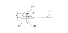
なお、スクライビングホイール32のスクライブ予定ラインSLまでの移動軌跡が、スクライブ予定ラインSLに垂直ではなく、図5に示すように、90°未満の角度θで傾斜するようにしてもよい。この場合は、移動軌跡の長さ(距離d)が1mm以上3mmmになるように、開始位置S0及び角度θを設定する必要がある。また、図5の場合は、門型フレーム2及びヘッド3の両方を移動させる必要がある。 Note that the movement trajectory of the
そして、スクライビングホイール32の刃先がスクライブ予定ラインSLに到達すると、門型フレーム2の移動を停止し、ガイド9を駆動することによってヘッド3をスクライブ予定ラインSLに沿ってX方向に移動させる。 When the cutting edge of the
ここで、ホイール保持部24aは回転自在であるので、ヘッド3のガラス基板Wに対する移動方向が変更されると、ホイール保持部24aは図4に示すように90°回転する。すなわち、スクライビングホイール32が90°回転する。この回転によって、スクライビングホイール32の刃先がガラス基板Wに食い込む。このようにして、スクライビングホイール32は、刃先がガラス基板Wに食い込んだ状態で、スクライブ予定ラインSLに沿って走査される。 Here, since the
ここで、スクライビングホイール32の方向が変えられることによって、変曲点の軌跡は曲線又は直線になる。軌跡が曲線になる場合は、軌跡の半径r(図4及び図5参照)は5mm未満にするのが好ましい。半径が5mm以上になると、開始点をスクライブ予定ライン上にセットした場合と同様に、刃先がガラス基板に食い込みにくくなる。 Here, when the direction of the
そして、スクライビングホイール32がガラス基板Wの端部近傍の終端まで走査されると、ヘッド3の移動は停止される。 When the
以上のようにしてスクライブされたガラス基板Wは、次工程である分断工程でスクライブ加工された溝の両側が押圧され、分断される。 The glass substrate W scribed in the above manner is pressed and divided on both sides of the groove scribed in the next cutting process.
以上のような加工方法では、スクライブの開始位置を、スクライブ予定ライン上ではなくスクライブ予定ラインから離れた位置にセットし、スクライビングホイール32の刃先をスクライブ予定ライン上で回転させるようにしたので、この回転時にスクライビングホイール32の刃先がガラス基板Wに食い込みやすくなる。このため、特に表面に強化層を有する強化ガラスに対して良好にスクライブを行うことができる。 In the above processing method, the scribing start position is set not on the planned scribe line but at a position away from the planned scribe line, and the cutting edge of the
[他の実施形態]
本発明は以上のような実施形態に限定されるものではなく、本発明の範囲を逸脱することなく種々の変形又は修正が可能である。[Other Embodiments]
The present invention is not limited to the above-described embodiments, and various changes or modifications can be made without departing from the scope of the present invention.
加工時において、門型フレーム及びヘッドの移動については、前記実施形態は一例であり、種々の変形が可能である。 In the processing, the embodiment is an example of the movement of the portal frame and the head, and various modifications are possible.
1 スクライブ装置
24 ホルダ
32 スクライビングホイール
SL スクライブ予定ライン
S0 開始位置
W ガラス基板1
Claims (4)
Translated fromJapaneseガラス基板上の前記スクライブ予定ラインから離れた開始位置に前記スクライビングホイールを圧接する第1工程と、
前記開始位置を起点として、前記スクライブ予定ラインに対して所定の角度を持った方向から、前記スクライブ予定ラインに向かって前記スクライビングホイールを前記ガラス基板に対して圧接しながら移動させる第2工程と、
前記スクライビングホイールが前記スクライブ予定ラインに到達した時点で、前記ガラス基板に対する前記スクライビングホイールの移動方向を前記第2工程における移動方向から前記スクライブ予定ラインに沿った方向に方向転換し、前記スクライビングホイールをガラス基板に対して圧接しながら前記スクライブ予定ラインに沿って移動させる第3工程と、
を含むガラス基板のスクライブ方法。A scribing method for scribing a glass substrate by moving a scribing wheel along a scribe line on the glass substrate having a reinforcing layer on the surface,
A first step of pressure-contacting the scribing wheel at a starting position away from the scribe line on the glass substrate;
A second step of moving the scribing wheelfrom the direction having a predetermined angle with respect to the scribe planned line starting from the start position while pressing the scribing wheel against the glass substrate toward the scribe planned line;
When the scribing wheel reaches the planned scribe line, the direction of movement of the scribing wheel relative to the glass substrate is changed from the moving direction inthe second step to thedirection along the planned scribe line,and the scribing wheel is A third step of moving along the scribe line while being pressed against the glass substrate;
A method for scribing a glass substrate.
Priority Applications (4)
| Application Number | Priority Date | Filing Date | Title |
|---|---|---|---|
| JP2011219696AJP5783873B2 (en) | 2011-10-04 | 2011-10-04 | Glass substrate scribing method |
| KR1020120103281AKR101361708B1 (en) | 2011-10-04 | 2012-09-18 | Scribe method for glass substrate |
| TW101134428ATWI508926B (en) | 2011-10-04 | 2012-09-20 | Scribe method for glass substrate |
| CN201210357123.1ACN103030265B (en) | 2011-10-04 | 2012-09-21 | Scribing method for glass substrate |
Applications Claiming Priority (1)
| Application Number | Priority Date | Filing Date | Title |
|---|---|---|---|
| JP2011219696AJP5783873B2 (en) | 2011-10-04 | 2011-10-04 | Glass substrate scribing method |
Publications (2)
| Publication Number | Publication Date |
|---|---|
| JP2013079166A JP2013079166A (en) | 2013-05-02 |
| JP5783873B2true JP5783873B2 (en) | 2015-09-24 |
Family
ID=48017722
Family Applications (1)
| Application Number | Title | Priority Date | Filing Date |
|---|---|---|---|
| JP2011219696AExpired - Fee RelatedJP5783873B2 (en) | 2011-10-04 | 2011-10-04 | Glass substrate scribing method |
Country Status (4)
| Country | Link |
|---|---|
| JP (1) | JP5783873B2 (en) |
| KR (1) | KR101361708B1 (en) |
| CN (1) | CN103030265B (en) |
| TW (1) | TWI508926B (en) |
Families Citing this family (5)
| Publication number | Priority date | Publication date | Assignee | Title |
|---|---|---|---|---|
| JP6201608B2 (en)* | 2013-10-08 | 2017-09-27 | 三星ダイヤモンド工業株式会社 | Scribing method |
| JP6302664B2 (en)* | 2013-12-20 | 2018-03-28 | 株式会社尼崎工作所 | Trigger groove forming method and forming apparatus using the same |
| JP6528356B2 (en)* | 2014-03-28 | 2019-06-12 | 三星ダイヤモンド工業株式会社 | Cutting method of resin sheet |
| JP6488644B2 (en)* | 2014-10-30 | 2019-03-27 | 三星ダイヤモンド工業株式会社 | Thick glass scribing method and scribing wheel for thick glass scribing |
| CN109204985B (en)* | 2018-08-27 | 2021-09-17 | 奕瑞影像科技(太仓)有限公司 | Packaging film removing device and method |
Family Cites Families (13)
| Publication number | Priority date | Publication date | Assignee | Title |
|---|---|---|---|---|
| JP4203177B2 (en) | 1999-03-18 | 2008-12-24 | 株式会社ベルデックス | Scribing method and apparatus |
| JP4249373B2 (en)* | 2000-05-16 | 2009-04-02 | 三星ダイヤモンド工業株式会社 | Method for cross-scribing brittle materials |
| JP2002338285A (en) | 2001-05-22 | 2002-11-27 | Matsushita Electric Ind Co Ltd | Glass cutting device and glass cutting method |
| JP2003292332A (en)* | 2002-03-29 | 2003-10-15 | Nakamura Tome Precision Ind Co Ltd | Scribing method and scribing device |
| FR2839508B1 (en)* | 2002-05-07 | 2005-03-04 | Saint Gobain | GLAZING CUTTING WITHOUT RIPPING |
| KR101181707B1 (en)* | 2004-05-20 | 2012-09-19 | 미쓰보시 다이야몬도 고교 가부시키가이샤 | Motherboard cutting method, motherboard scribing apparatus, program and recording medium |
| JP5467490B2 (en)* | 2007-08-03 | 2014-04-09 | 日本電気硝子株式会社 | Method for producing tempered glass substrate and tempered glass substrate |
| JP2010052995A (en)* | 2008-08-29 | 2010-03-11 | Mitsuboshi Diamond Industrial Co Ltd | Method for scribing mother substrate |
| TWI501415B (en)* | 2009-02-24 | 2015-09-21 | Mitsuboshi Diamond Ind Co Ltd | A trench processing tool, a trench processing method and a cutting device using a thin film solar cell |
| BRPI0924978B1 (en)* | 2009-04-10 | 2019-11-12 | Bando Kiko Co | Scratching apparatus and glass plate scratching method |
| JP2011088382A (en)* | 2009-10-23 | 2011-05-06 | Mitsuboshi Diamond Industrial Co Ltd | Breaking device and breaking method |
| TWI494284B (en) | 2010-03-19 | 2015-08-01 | Corning Inc | Mechanical scoring and separation of strengthened glass |
| US8864005B2 (en)* | 2010-07-16 | 2014-10-21 | Corning Incorporated | Methods for scribing and separating strengthened glass substrates |
- 2011
- 2011-10-04JPJP2011219696Apatent/JP5783873B2/ennot_activeExpired - Fee Related
- 2012
- 2012-09-18KRKR1020120103281Apatent/KR101361708B1/ennot_activeExpired - Fee Related
- 2012-09-20TWTW101134428Apatent/TWI508926B/ennot_activeIP Right Cessation
- 2012-09-21CNCN201210357123.1Apatent/CN103030265B/ennot_activeExpired - Fee Related
Also Published As
| Publication number | Publication date |
|---|---|
| TW201323361A (en) | 2013-06-16 |
| KR101361708B1 (en) | 2014-02-10 |
| KR20130036706A (en) | 2013-04-12 |
| TWI508926B (en) | 2015-11-21 |
| CN103030265A (en) | 2013-04-10 |
| JP2013079166A (en) | 2013-05-02 |
| CN103030265B (en) | 2015-05-27 |
Similar Documents
| Publication | Publication Date | Title |
|---|---|---|
| JP5783873B2 (en) | Glass substrate scribing method | |
| KR101651557B1 (en) | Glass plate scribing device | |
| JP5433797B2 (en) | Coated optical fiber coating removal method and coated optical fiber coating removal apparatus | |
| JP5129826B2 (en) | Breaking method for brittle material substrate | |
| TW201202159A (en) | Scribing apparatus for glass panel and scribing method thereof | |
| TWI527674B (en) | Method and apparatus for scribing brittle material substrate | |
| JP6847398B2 (en) | Sequential molding method | |
| JP4740774B2 (en) | Winding terminal processing method and apparatus | |
| JP2010166799A (en) | Method and apparatus for constituting coils | |
| JP2013139375A (en) | Method and device for scribing tempered glass substrate | |
| JP2009095901A (en) | Method and apparatus for dividing bonded substrate | |
| CN209684811U (en) | an initial positioning mechanism | |
| JP2015164895A (en) | Parting device | |
| CN104210039B (en) | Diamond wire cutting machine and cutting method of the diamond wire cutting machine | |
| TWI474983B (en) | Scoring Method and Breaking Method of Mother Substrate | |
| TWI471277B (en) | Scribe device | |
| KR20120026192A (en) | A scribing unit | |
| JP2014217982A (en) | Scribe device and scribe method | |
| JP2013220637A (en) | Printing apparatus capable of printing at various angle | |
| CN104416685B (en) | Cutting machine and cutting method of the cutting machine | |
| TWI510343B (en) | Diamond line cutting machine and cutting method using same | |
| TWI715868B (en) | Scribing method and scribing apparatus | |
| JP2013159540A (en) | Scribing device | |
| JP5731942B2 (en) | Mother board cutting method | |
| TWM535399U (en) | Improved wafer carrying device structure |
Legal Events
| Date | Code | Title | Description |
|---|---|---|---|
| A621 | Written request for application examination | Free format text:JAPANESE INTERMEDIATE CODE: A621 Effective date:20140502 | |
| A977 | Report on retrieval | Free format text:JAPANESE INTERMEDIATE CODE: A971007 Effective date:20140918 | |
| A131 | Notification of reasons for refusal | Free format text:JAPANESE INTERMEDIATE CODE: A131 Effective date:20141028 | |
| A521 | Written amendment | Free format text:JAPANESE INTERMEDIATE CODE: A523 Effective date:20141210 | |
| TRDD | Decision of grant or rejection written | ||
| A01 | Written decision to grant a patent or to grant a registration (utility model) | Free format text:JAPANESE INTERMEDIATE CODE: A01 Effective date:20150623 | |
| A61 | First payment of annual fees (during grant procedure) | Free format text:JAPANESE INTERMEDIATE CODE: A61 Effective date:20150721 | |
| R150 | Certificate of patent or registration of utility model | Ref document number:5783873 Country of ref document:JP Free format text:JAPANESE INTERMEDIATE CODE: R150 | |
| LAPS | Cancellation because of no payment of annual fees |