JP5778376B2 - Method for atomizing a material in a coating process - Google Patents
Method for atomizing a material in a coating processDownload PDFInfo
- Publication number
- JP5778376B2 JP5778376B2JP2008548728AJP2008548728AJP5778376B2JP 5778376 B2JP5778376 B2JP 5778376B2JP 2008548728 AJP2008548728 AJP 2008548728AJP 2008548728 AJP2008548728 AJP 2008548728AJP 5778376 B2JP5778376 B2JP 5778376B2
- Authority
- JP
- Japan
- Prior art keywords
- supply conduit
- liquid
- gas
- substrate
- atomizer
- Prior art date
- Legal status (The legal status is an assumption and is not a legal conclusion. Google has not performed a legal analysis and makes no representation as to the accuracy of the status listed.)
- Expired - Fee Related
Links
Images

Classifications
- C—CHEMISTRY; METALLURGY
- C23—COATING METALLIC MATERIAL; COATING MATERIAL WITH METALLIC MATERIAL; CHEMICAL SURFACE TREATMENT; DIFFUSION TREATMENT OF METALLIC MATERIAL; COATING BY VACUUM EVAPORATION, BY SPUTTERING, BY ION IMPLANTATION OR BY CHEMICAL VAPOUR DEPOSITION, IN GENERAL; INHIBITING CORROSION OF METALLIC MATERIAL OR INCRUSTATION IN GENERAL
- C23C—COATING METALLIC MATERIAL; COATING MATERIAL WITH METALLIC MATERIAL; SURFACE TREATMENT OF METALLIC MATERIAL BY DIFFUSION INTO THE SURFACE, BY CHEMICAL CONVERSION OR SUBSTITUTION; COATING BY VACUUM EVAPORATION, BY SPUTTERING, BY ION IMPLANTATION OR BY CHEMICAL VAPOUR DEPOSITION, IN GENERAL
- C23C16/00—Chemical coating by decomposition of gaseous compounds, without leaving reaction products of surface material in the coating, i.e. chemical vapour deposition [CVD] processes
- C23C16/44—Chemical coating by decomposition of gaseous compounds, without leaving reaction products of surface material in the coating, i.e. chemical vapour deposition [CVD] processes characterised by the method of coating
- C23C16/54—Apparatus specially adapted for continuous coating
- C23C16/545—Apparatus specially adapted for continuous coating for coating elongated substrates
- B—PERFORMING OPERATIONS; TRANSPORTING
- B05—SPRAYING OR ATOMISING IN GENERAL; APPLYING FLUENT MATERIALS TO SURFACES, IN GENERAL
- B05B—SPRAYING APPARATUS; ATOMISING APPARATUS; NOZZLES
- B05B13/00—Machines or plants for applying liquids or other fluent materials to surfaces of objects or other work by spraying, not covered by groups B05B1/00 - B05B11/00
- B05B13/02—Means for supporting work; Arrangement or mounting of spray heads; Adaptation or arrangement of means for feeding work
- B05B13/04—Means for supporting work; Arrangement or mounting of spray heads; Adaptation or arrangement of means for feeding work the spray heads being moved during spraying operation
- B05B13/0463—Installation or apparatus for applying liquid or other fluent material to moving work of indefinite length
- B—PERFORMING OPERATIONS; TRANSPORTING
- B05—SPRAYING OR ATOMISING IN GENERAL; APPLYING FLUENT MATERIALS TO SURFACES, IN GENERAL
- B05B—SPRAYING APPARATUS; ATOMISING APPARATUS; NOZZLES
- B05B17/00—Apparatus for spraying or atomising liquids or other fluent materials, not covered by the preceding groups
- B05B17/04—Apparatus for spraying or atomising liquids or other fluent materials, not covered by the preceding groups operating with special methods
- B05B17/06—Apparatus for spraying or atomising liquids or other fluent materials, not covered by the preceding groups operating with special methods using ultrasonic or other kinds of vibrations
- B05B17/0607—Apparatus for spraying or atomising liquids or other fluent materials, not covered by the preceding groups operating with special methods using ultrasonic or other kinds of vibrations generated by electrical means, e.g. piezoelectric transducers
- B—PERFORMING OPERATIONS; TRANSPORTING
- B05—SPRAYING OR ATOMISING IN GENERAL; APPLYING FLUENT MATERIALS TO SURFACES, IN GENERAL
- B05B—SPRAYING APPARATUS; ATOMISING APPARATUS; NOZZLES
- B05B7/00—Spraying apparatus for discharge of liquids or other fluent materials from two or more sources, e.g. of liquid and air, of powder and gas
- B05B7/02—Spray pistols; Apparatus for discharge
- B05B7/04—Spray pistols; Apparatus for discharge with arrangements for mixing liquids or other fluent materials before discharge
- B05B7/0416—Spray pistols; Apparatus for discharge with arrangements for mixing liquids or other fluent materials before discharge with arrangements for mixing one gas and one liquid
- B05B7/0441—Spray pistols; Apparatus for discharge with arrangements for mixing liquids or other fluent materials before discharge with arrangements for mixing one gas and one liquid with one inner conduit of liquid surrounded by an external conduit of gas upstream the mixing chamber
- B05B7/045—Spray pistols; Apparatus for discharge with arrangements for mixing liquids or other fluent materials before discharge with arrangements for mixing one gas and one liquid with one inner conduit of liquid surrounded by an external conduit of gas upstream the mixing chamber the gas and liquid flows being parallel just upstream the mixing chamber
- C—CHEMISTRY; METALLURGY
- C23—COATING METALLIC MATERIAL; COATING MATERIAL WITH METALLIC MATERIAL; CHEMICAL SURFACE TREATMENT; DIFFUSION TREATMENT OF METALLIC MATERIAL; COATING BY VACUUM EVAPORATION, BY SPUTTERING, BY ION IMPLANTATION OR BY CHEMICAL VAPOUR DEPOSITION, IN GENERAL; INHIBITING CORROSION OF METALLIC MATERIAL OR INCRUSTATION IN GENERAL
- C23C—COATING METALLIC MATERIAL; COATING MATERIAL WITH METALLIC MATERIAL; SURFACE TREATMENT OF METALLIC MATERIAL BY DIFFUSION INTO THE SURFACE, BY CHEMICAL CONVERSION OR SUBSTITUTION; COATING BY VACUUM EVAPORATION, BY SPUTTERING, BY ION IMPLANTATION OR BY CHEMICAL VAPOUR DEPOSITION, IN GENERAL
- C23C16/00—Chemical coating by decomposition of gaseous compounds, without leaving reaction products of surface material in the coating, i.e. chemical vapour deposition [CVD] processes
- C23C16/44—Chemical coating by decomposition of gaseous compounds, without leaving reaction products of surface material in the coating, i.e. chemical vapour deposition [CVD] processes characterised by the method of coating
- C23C16/448—Chemical coating by decomposition of gaseous compounds, without leaving reaction products of surface material in the coating, i.e. chemical vapour deposition [CVD] processes characterised by the method of coating characterised by the method used for generating reactive gas streams, e.g. by evaporation or sublimation of precursor materials
- C23C16/4486—Chemical coating by decomposition of gaseous compounds, without leaving reaction products of surface material in the coating, i.e. chemical vapour deposition [CVD] processes characterised by the method of coating characterised by the method used for generating reactive gas streams, e.g. by evaporation or sublimation of precursor materials by producing an aerosol and subsequent evaporation of the droplets or particles
- B—PERFORMING OPERATIONS; TRANSPORTING
- B05—SPRAYING OR ATOMISING IN GENERAL; APPLYING FLUENT MATERIALS TO SURFACES, IN GENERAL
- B05D—PROCESSES FOR APPLYING FLUENT MATERIALS TO SURFACES, IN GENERAL
- B05D1/00—Processes for applying liquids or other fluent materials
- B05D1/02—Processes for applying liquids or other fluent materials performed by spraying
- B—PERFORMING OPERATIONS; TRANSPORTING
- B05—SPRAYING OR ATOMISING IN GENERAL; APPLYING FLUENT MATERIALS TO SURFACES, IN GENERAL
- B05D—PROCESSES FOR APPLYING FLUENT MATERIALS TO SURFACES, IN GENERAL
- B05D7/00—Processes, other than flocking, specially adapted for applying liquids or other fluent materials to particular surfaces or for applying particular liquids or other fluent materials
- B05D7/02—Processes, other than flocking, specially adapted for applying liquids or other fluent materials to particular surfaces or for applying particular liquids or other fluent materials to macromolecular substances, e.g. rubber
Landscapes
- Chemical & Material Sciences (AREA)
- Mechanical Engineering (AREA)
- Organic Chemistry (AREA)
- Chemical Kinetics & Catalysis (AREA)
- Engineering & Computer Science (AREA)
- Materials Engineering (AREA)
- General Chemical & Material Sciences (AREA)
- Metallurgy (AREA)
- Dispersion Chemistry (AREA)
- Application Of Or Painting With Fluid Materials (AREA)
- Electroluminescent Light Sources (AREA)
- Chemical Vapour Deposition (AREA)
- Physical Or Chemical Processes And Apparatus (AREA)
- Special Spraying Apparatus (AREA)
- Nozzles (AREA)
Description
Translated fromJapanese本発明は、液状材料の噴霧化に関し、特に連続した化学蒸着プロセスのための蒸気の作成に関する。 The present invention relates to atomization of liquid materials, and more particularly to the creation of vapors for continuous chemical vapor deposition processes.
化学的蒸着技術またはモノマー蒸着技術は、多くの有用な製品の作成に、好都合に適用されてきた。例えば、効果的な水分及び酸素バリヤーフィルムは、基材に金属酸化物の交替的な層を蒸着技術とスパッターリング技術を適用して作成されている。この種のフィルムの水分及び酸素遮断性及び柔軟性は、食品並びに薬の包装、及び太陽電池、OLED(有機発光ダイオード)装置並びに有機マイクロエレクトロニクス装置のような電子装置の保護膜のような多種多様な応用に有用である。 Chemical vapor deposition techniques or monomer vapor deposition techniques have been advantageously applied in the creation of many useful products. For example, effective moisture and oxygen barrier films have been created by applying alternating layers of metal oxides to a substrate using deposition and sputtering techniques. The moisture and oxygen barrier properties and flexibility of this type of film vary widely such as food and medicine packaging, and protective films for electronic devices such as solar cells, OLED (organic light emitting diode) devices and organic microelectronic devices. It is useful for various applications.
モノマー蒸着によるポリマーフイルム層の製造において、重合可能なモノマーをアトマイザに供給し、次に、噴霧化された液体粒子を蒸発室に通してから気化したモノマーをターゲット表面上へ導くことは公知である。気化したモノマーは、続いて、例えば、紫外線によって重合させられて、有益な特性をもつ重合物質の薄層を形成する。 In the production of polymer film layers by monomer vapor deposition, it is known to feed a polymerizable monomer to an atomizer and then to pass the atomized liquid particles through an evaporation chamber before directing the vaporized monomer onto the target surface. . The vaporized monomer is subsequently polymerized, for example by ultraviolet light, to form a thin layer of polymeric material with beneficial properties.
化学蒸着による無機膜層の製造において、有機又は有機金属の前駆体をアトマイザに供給してから、噴霧化された液体粒子を蒸発室に通して気化した前駆体をターゲット表面に導くことは公知である。気化した前駆体はターゲット表面で他のガス状または蒸気材料に、例えば、熱エネルギーまたはプラズマによって、反応されて、有益な特性をもつ無機材料の薄層を形成する。 In the production of inorganic film layers by chemical vapor deposition, it is well known that an organic or organometallic precursor is supplied to an atomizer and then the vaporized precursor is guided to the target surface by passing the atomized liquid particles through an evaporation chamber. is there. The vaporized precursor is reacted at the target surface with other gaseous or vapor materials, for example by thermal energy or plasma, to form a thin layer of inorganic material with beneficial properties.
スプレーコーティングによるポリマー又は生理活性薄層の製造において、ポリマーまたは生理活性材料溶液及び(有機又は水性の)溶解剤をアトマイザに供給してから、噴霧化された液体粒子をターゲット表面に導いて、有益な特性をもつ薄いポリマー又は生理活性材料のコーティングを形成することは公知である。 In the production of a polymer or bioactive thin layer by spray coating, the polymer or bioactive material solution and the (organic or aqueous) solubilizer are supplied to the atomizer, and then the atomized liquid particles are guided to the target surface, which is beneficial It is known to form thin polymer or bioactive material coatings with unique properties.
本開示は、液体の噴霧化と気化のための装置と方法、及びこの噴霧化方法から作られる物品に関する。蒸気コーティングプロセスにおいて使用されるとき、開示される方法は、より小さい液滴直径、液滴直径の均一性の改良、及び、液滴直径の時間に関する安定性の改善を提供する。液滴の均一性と安定性の改良によって、従来の方法と比べて、気化速度、蒸気流速及びコーティング厚さの均一性が導かれる。 The present disclosure relates to apparatus and methods for atomizing and vaporizing liquids and articles made from the atomizing methods. When used in a vapor coating process, the disclosed methods provide smaller droplet diameters, improved droplet diameter uniformity, and improved stability with respect to droplet diameter time. Improvements in droplet uniformity and stability lead to vaporization rate, vapor flow rate and coating thickness uniformity compared to conventional methods.
超音波アトマイザは、さまざまなアプリケーションのための液体粒子の微細なスプレーをもたらせるために使用されてきた。しかし、超音波及び従来型のアトマイザは両方とも液滴サイズの微細化、良好な液滴サイズの均一性、及び液滴サイズの時間に関する安定性を達成できずにいる。 Ultrasonic atomizers have been used to provide a fine spray of liquid particles for a variety of applications. However, both ultrasonic and conventional atomizers fail to achieve drop size refinement, good drop size uniformity, and drop size stability over time.
1つの実施形態において開示される、液体を噴霧化する方法は、(1)一端に放出口を有する液体供給導管と、この放出口の上流で液体供給導管に開口するガス供給導管を含むアトマイザと、振動エネルギーを放出口に与えるための手段を提供すること、(2)ガス供給導管を通してガスを流すのと同時に、液体供給導管を通して液体を放出口に流すこと、及び(3)放出口から出る液体を噴霧化するために振動エネルギーをアトマイザに与えることを含む。1つの実施形態において、液体及びガス導管は、互いに相対的に同軸に配置される。 A method for atomizing a liquid disclosed in one embodiment includes (1) a liquid supply conduit having an outlet at one end, and an atomizer including a gas supply conduit that opens to the liquid supply conduit upstream of the outlet. Providing means for imparting vibrational energy to the outlet; (2) flowing gas through the gas supply conduit at the same time as flowing gas through the liquid supply conduit; and (3) exiting the outlet. Including applying vibration energy to the atomizer to atomize the liquid. In one embodiment, the liquid and gas conduits are arranged coaxially relative to each other.
さらなる実施形態において、開示される基材をコーティングする方法は、(1)基材を提供すること、(2)一端に放出口を有する液体供給導管と、この放出口の上流で液体供給導管に開口するガス供給導管を含むアトマイザと、振動エネルギーを放出口に与えるための手段を提供すること、(3)ガス供給導管を通してガスを流すのと同時に、液体供給導管を通して液体を放出口に流すこと、及び(4)放出口から出ていく液体を噴霧化して、蒸気を形成するために液体を気化させ、基材上へ蒸気を凝結させる手段から、振動エネルギーをアトマイザに与えることを含む。 In a further embodiment, the disclosed method of coating a substrate comprises (1) providing a substrate, (2) a liquid supply conduit having an outlet at one end, and a liquid supply conduit upstream of the outlet. Providing an atomizer including an open gas supply conduit and means for imparting vibrational energy to the outlet; (3) flowing gas through the liquid supply conduit to the outlet simultaneously with flowing gas through the gas supply conduit; And (4) atomizing the liquid exiting the outlet, vaporizing the liquid to form a vapor, and applying vibrational energy to the atomizer from means for condensing the vapor onto the substrate.
別の実施形態において、(1)基材を提供すること、(2)一端に放出口を有する液体供給導管と、この放出口の上流で液体供給導管に開口するガス供給導管を含むアトマイザと、振動エネルギーを放出口に与えるための手段を提供すること、(3)ガス供給導管を通してガスを流すのと同時に、液体供給導管を通して液体を放出口に流すこと、及び(4)放出口から出ていく液体を噴霧化して、蒸気を形成するために液体を気化させ、基材上へ蒸気を凝結させる手段から、振動エネルギーをアトマイザに与えることを含む、基材をコーティングする方法が開示される。 In another embodiment, (1) providing a substrate, (2) an atomizer including a liquid supply conduit having an outlet at one end and a gas supply conduit opening to the liquid supply conduit upstream of the outlet; Providing means for imparting vibrational energy to the outlet, (3) flowing gas through the gas supply conduit at the same time as flowing gas through the liquid supply conduit, and (4) exiting the outlet Disclosed is a method of coating a substrate that includes applying vibrational energy to the atomizer from means for atomizing the liquid to vaporize the liquid to form a vapor and condensing the vapor onto the substrate.
また、更なる実施態様において、(1)基材を提供すること、(2)一端に放出口を有する液体供給導管と、この放出口の上流で液体供給導管に開口するガス供給導管を含むアトマイザと、振動エネルギーを放出口に与えるための手段を提供すること、(3)ガス供給導管を通してガスを流すのと同時に、液体供給導管を通して液体を放出口に流すこと、及び(4)放出口から出ていく液体を噴霧化して、蒸気を形成するために液体を気化させ、反応性ガス中において蒸気を基材に接触させる手段から、振動エネルギーをアトマイザに与えることを含む、基材をコーティングする方法が開示される。 In a further embodiment, the atomizer includes (1) providing a substrate, (2) a liquid supply conduit having an outlet at one end, and a gas supply conduit opening to the liquid supply conduit upstream of the outlet. Providing a means for imparting vibrational energy to the discharge outlet, (3) flowing gas through the gas supply conduit and simultaneously flowing liquid through the liquid supply conduit to the discharge outlet, and (4) from the discharge outlet. Coating the substrate, including atomizing the exiting liquid, vaporizing the liquid to form a vapor, and applying vibrational energy to the atomizer from a means of contacting the vapor with the substrate in a reactive gas A method is disclosed.
(注:上記ステップは、明確化のために番号をつけており、ステップがなんらかの特定の順番において実行されるべきであることを意味する目的ではない)。 (Note: The above steps are numbered for clarity and are not meant to imply that the steps should be performed in any particular order).
図1は、アトマイザ38の横断面図を示す。アトマイザ38は、部分的にアウタハウジング46に含まれるノズル本体55を含み、液体供給ライン36によって液体材料34のソースに一端で接続されている。反対端において、アトマイザノズル本体55は、アトマイザ38に入っていく液体材料34がそこから噴霧化される噴霧化面60を含む。FIG. 1 shows a cross-sectional view of the
アトマイザ38に液体材料を供給する液体供給ライン36は、液体供給導管50に取り付けられ、アトマイザ38の噴霧化面60の中央に位置する放出口52の一端で終端する。ガス供給導管54は、ガス供給ライン42からアトマイザ38にガスを供給する。ガス供給導管54は、放出口52の上流で、ポート56で液体供給導管50に開口する。1つの実施形態において、ガス供給導管54は、液体供給導管50の内腔の少なくとも80パーセント程度で、液体供給導管に開口する。他の実施形態では、ガス供給導管54は、内腔の80パーセント未満程度で、液体供給導管に開口する。当業者によって認識されるように、前記方法は様々な構成を使って実行できる。A
更なる実施形態において、ガス供給導管54は、液体供給導管50の内腔の100パーセント程度で、液体供給導管に開口する。この実施形態において、液体供給導管50及びガス供給導管54は、互いに対して同軸に、配置される。ポート56と放出口52との間のアトマイザの領域で一旦組み合されると、液体とガスの流れは放出口52を出てアトマイザ38の噴霧化面60から噴霧化される。In a further embodiment, the
アトマイザ38は、更に振動エネルギー58をノズル本体55に与えるための手段を含む。振動エネルギーを与えるための好適な手段に、電気エネルギーを機械的エネルギーまたは振動エネルギーに変換できるトランスデューサが含まれる。1つの実施形態において、電気エネルギーを機械的エネルギーに変換するために圧電変換器を利用する超音波アトマイザが採用される。トランスデューサは、発電機から電気的入力を受け取って、そのエネルギーを同一周波数の振動運動に変換する。 The
放出口52に隣接した噴霧化面60の円錐ヘッドは散布されるスプレーパターン64を提供して、この種の噴霧化装置が面上に薄く均一な適用範囲を必要とするアプリケーションに好適になるようにする。いくつかの実施形態では、冷媒供給口62から入り、冷媒出口ポート63から出る冷却風が、圧電性の超音波振動子が過熱されないように使用される。典型的な圧電性の超音波アトマイザは、本明細書に参照として組み込まれている、米国特許番号4,337,896(ベルガーら(Berger et al))において開示されている。 The conical head of the atomizing
本明細書において開示される噴霧化処理に好適な材料には、モノマー、オリゴマー、樹脂、ワックス、有機化合物、有機金属化合物、生物学的活性材料及びそれらの組み合わせが含まれる。これらの材料は、室温において液体であるか、または温度上昇されて溶解された固体であってよい。1つの実施形態において、(メタ)アクリレートモノマーは、本明細書において記載されている噴霧化法によって蒸着される。適切な(メタ)アクリレートモノマーは、本明細書に参照として組み込まれている以下の特許、5,440,446(ショーら(Shaw, et al.))、5,725,909(ショーら(Shaw, et al.))、6,231,939(ショーら(Shaw, et al.))、6,420,003(ショーら(Shaw, et al.))において開示されている。Suitable materials for the nebulization process disclosed herein include monomers, oligomers, resins, waxes, organic compounds, organometallic compounds, biologically active materials, and combinations thereof. These materials may be liquids at room temperature or solids that are dissolved at elevated temperatures. In one embodiment,(meth) acrylate monomer is deposited by atomization method described herein. Suitable(meth) acrylate monomers, the following patents are incorporated herein by reference, 5,440,446 (Shaw et al. (Shaw, et al.)) , 5,725,909 ( Shaw et al. ( Shaw, et al.), 6,231,939 (Shaw, et al.), 6,420,003 (Shaw, et al.).
本噴霧化処理に使用される適切な他の材料には、本明細書に参照として組み込まれている以下の米国特許、6,468,595(ミカエルら(Mikhael et al.))、6,660,339(ダッタら(Datta et al.))、6,544,600(アフィニトら(Affinito et al.))、6,811,829(アフィニトら(Affinito et al.))、6,682,782、(ユングら(Jung et al.))6,656,537(アフィニトら(Affinito et al.))、6,475,571(越後ら)、6,284,050(シら(Shi et al.))、6,207,238及び6,207,239(アフィニトら(Affinito et al.))、5,061,509(内藤ら)、6,045,864(ライアンズら(Lyons et al.))、2005/0089673(フレミングら(Fleming et al.))、6,203,898(ケーラーら(Kohler et al.))、6,794,196(フォナシ(Fonash et al.)ら)、6,803,069(パトニアックら(Patniak et al.))、及び、5,869,127(ツォンら(Zhong et al.))に記載されているように、エポキシ類、ビニルエーテル類、フルオロ含有ポリマー類、スチレン含有ポリマー類、アセチレン類、ポリアミド、アクリルアミド類、パリレン類、ワックス類、フルオロポリエーテル類、ポリアミン類、ジアリージフェニルシラン類、金属アルコキシド類、金属アルキル類、シリコーン類、油類、染料類、タンパク質類、ペプチド類、ポリペプチド類、脂質類、炭水化物類、酵素類、核酸類、ポリ核酸類、薬物類、薬代謝産物類、セル類、セル類材料及び微生物類、が挙げられるが、これに限定されない。 Other suitable materials used in the nebulization process include the following US patents, 6,468,595 (Mikhael et al.), 6,660, incorporated herein by reference. , 339 (Datta et al.), 6,544,600 (Affinito et al.), 6,811,829 (Affinito et al.), 6,682,782. (Jung et al.) 6,656,537 (Affinito et al.), 6,475,571 (Echigo et al.), 6,284,050 (Shi et al. )), 6,207,238 and 6,207,239 (Affinito et al.), 5,061,509 (Naito et al.), 6,045,864 (Lyons et al.)) 2005/0089673 (Fleming et al.), 6,203, 898 (Kohler et al.), 6,794,196 (Fonash et al. Et al.), 6,803,069 (Patniak et al.)), And 5,869, 127 (Zhong et al.), Epoxies, vinyl ethers, fluoro-containing polymers, styrene-containing polymers, acetylenes, polyamides, acrylamides, parylenes, waxes, fluoro Polyethers, polyamines, diarydiphenylsilanes, metal alkoxides, metal alkyls, silicones, oils, dyes, proteins, peptides, polypeptides, lipids, carbohydrates, enzymes, nucleic acids , Polynucleic acids, drugs, drug metabolites, cells, cell materials and microorganisms, but are not limited thereto.
様々な反応性及び非反応性のガス類は、本明細書において記載されている噴霧化法に適切であろう。本プロセスに使用するのに好適な不活性ガスには、窒素、アルゴン、ヘリウム及びネオンが含まれる。1つの実施形態において、窒素が、用いられる。窒素はまた、CVDまたはプラズマCVDのための反応性ガスとして用いることもできる。酸素、オゾン、亜酸化窒素、水素、硫化水素、四フッ化炭素、メタン及びアンモニアのような他の反応性ガスもまた、本明細書において開示されるプロセスで用いられてよい。 A variety of reactive and non-reactive gases will be suitable for the nebulization process described herein. Inert gases suitable for use in the process include nitrogen, argon, helium and neon. In one embodiment, nitrogen is used. Nitrogen can also be used as a reactive gas for CVD or plasma CVD. Other reactive gases such as oxygen, ozone, nitrous oxide, hydrogen, hydrogen sulfide, carbon tetrafluoride, methane and ammonia may also be used in the processes disclosed herein.
噴霧化を容易にするために、噴霧化処理において使用する液体及びガス材は、加熱または冷却されてもよい。液体及びガス流は、独立して、室温より下から液体材料の劣化温度以下及びアトマイザの温度限界以下の範囲で、任意の温度に加熱または冷却されてよい。若干の超音波アトマイザは、約150℃の温度上限を有する。1つの実施形態において、液体流は、約50℃まで加熱される。1つの実施形態において、ガス流体は、約100℃まで加熱される。 To facilitate atomization, the liquid and gas materials used in the atomization process may be heated or cooled. The liquid and gas streams may be independently heated or cooled to any temperature ranging from below room temperature to below the degradation temperature of the liquid material and below the temperature limit of the atomizer. Some ultrasonic atomizers have an upper temperature limit of about 150 ° C. In one embodiment, the liquid stream is heated to about 50 ° C. In one embodiment, the gas fluid is heated to about 100 ° C.
開示されるプロセスは、通常、比較的低いガス流速、例えば毎分0.5リットル未満(毎分500標準立方センチメートル(SCCM))を用いて実行される。1つの実施形態において、ガス流速は、20SCCM未満である。本明細書において開示される噴霧化処理の適切な液体流速は1分につき約0.01〜約30ミリリットルの範囲である。1つの実施形態において、液体流速は、1分につき約0.1〜約5ミリリットルである。 The disclosed processes are typically performed using relatively low gas flow rates, for example, less than 0.5 liters per minute (500 standard cubic centimeters per minute (SCCM)). In one embodiment, the gas flow rate is less than 20 SCCM. Suitable liquid flow rates for the nebulization process disclosed herein range from about 0.01 to about 30 milliliters per minute. In one embodiment, the liquid flow rate is about 0.1 to about 5 milliliters per minute.
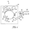
図2は、多層コーティングを生じるロールツーロール処理10を示しており、上記のアトマイザ38を使用することができる。プロセス10において、基材12は、第1のロール14から展開されて、アイドラ18によってプロセスドラム16の周囲に導かれて、アイドラ22によって第2のロール20へと導かれる。このプロセスは、金属酸化物または他の適切な材料の蒸着のための多様な工具を備える真空チャンバ(または大気圧もしくはより高い圧力の制御雰囲気チャンバ)24において実行されてよく、金属酸化物のような金属層の蒸着のための基材表面の処理用のプラズマ処理ステーション26及び金属スパッタステーション28と30を含むことができる。また、チャンバ24内には、上記の液体モノマーのような液体材料の蒸着のための道具がある。蒸気発生器32は、液体供給ライン36によってアトマイザ38に接続されている液体モノマー34のディスペンサー、及びガス・ディスペンサー40からアトマイザ38にガスが供給されるガス供給ライン42を含む。 FIG. 2 shows a roll-to-
噴霧化処理において、アトマイザ38によって形成される液滴のスプレーは、モノマーを完全に蒸気に変えるために、気化器43に導かれる。蒸気は、ノズル44から基材12上に送出されて、そこで凝縮する。基材が「D」方向に回転しているプロセスドラム16と接触して進むにつれて、液体モノマーの重合を開始できる硬化ソース21へ進むことになる。好適なソース21は、紫外線、熱、プラズマ及び電子線照射を含む。 In the atomization process, the spray of droplets formed by the
1つの実施形態において、プロセスドラムは、基材12上の液体蒸気の凝結をより良好に促進する冷却のため、冷却剤の循環を備えている。 In one embodiment, the process drum is provided with a coolant circulation for cooling that better promotes condensation of the liquid vapor on the
本明細書において記載されている噴霧化及びコーティングプロセスは、秒速約0.05〜約760センチメートル(毎分0.1〜約1500フィート)のラインスピードで実行されてよい。1つの実施形態において、プロセスは、約0.5cm/秒(1フィート/分)〜約200cm/秒(400フィート/分)のラインスピードで実行される。 The atomization and coating process described herein may be performed at a line speed of about 0.05 to about 760 centimeters per second (0.1 to about 1500 feet per minute). In one embodiment, the process is performed at a line speed of about 0.5 cm / sec (1 ft / min) to about 200 cm / sec (400 ft / min).
プロセスは、真空条件、大気圧またはより高い圧力の下で実行されてよい。1つの実施形態において、プロセスは、約1.3mPa(10−5Torr)〜約107kPa(800Torr)の圧力の下で実行される。さらなる実施形態において、プロセスは約13mPa(10−4Torr)〜約0.3kPa(2Torr)の圧力で実行される。The process may be performed under vacuum conditions, atmospheric pressure or higher pressure. In one embodiment, the process is carried out under a pressure of about 1.3 mPa (10−5 Torr) to about 107 kPa (800 Torr). In a further embodiment, the process is performed at a pressure of about 13 mPa (10−4 Torr) to about 0.3 kPa (2 Torr).
本明細書において開示されるプロセスに用いられる好適な基材には、紙、重合材料及びそれらの組み合わせのようなロールツーロール処理ができる可撓性材料が含まれる。特に有用なポリマー基材には、例えばポリプロピレン(PP)のような、さまざまなポリオレフィン類、例えばポリエチレンテレフタラート(PET)のようなさまざまなポリエステル類、フルオレンポリエステル(FPE))、ポリメチルメタクリレート(PMMA)及びポリエチレンナフタレート(PEN)のような他のポリマー類、ポリエーテルサルフォン(PES)、ポリエステルカルボネート(PC)、ポリエーテルイミド(PEI)、ポリアリーレート(PAR)ポリイミド(PI))が含まれる。更に役立つ材料には、商品名アートン(ARTON)(日本合成ゴム(株)、東京、日本)及びアバトレル(AVATREL)(オハイオ州ブレックスビル、B.F.グッドリッチ社(B.F. Goodrich, Brecksville, Ohio))で販売されているような多環式オレフィンが含まれる。 Suitable substrates for use in the processes disclosed herein include flexible materials that can be roll-to-roll processed, such as paper, polymeric materials, and combinations thereof. Particularly useful polymer substrates include various polyolefins such as polypropylene (PP), various polyesters such as polyethylene terephthalate (PET), fluorene polyester (FPE)), polymethyl methacrylate (PMMA). ) And other polymers such as polyethylene naphthalate (PEN), polyethersulfone (PES), polyester carbonate (PC), polyetherimide (PEI), polyarylate (PAR) polyimide (PI)) included. Further useful materials include ARTON (Nippon Synthetic Rubber Co., Tokyo, Japan) and AVATREL (Breakville, Ohio, BF Goodrich, Brecksville, Ohio) And polycyclic olefins such as those sold in
場合によっては、基材は、フィルムの連続ロールよりむしろ個別部材である。個別部材は蒸気供給源を通って移動することができるか、または、個別部材はコーティングプロセスの間、静止していてよい。好適な基材には、シリコンウエハ、電子又は光学的装置、ガラス、金属及びプラスチック部材が含まれる。 In some cases, the substrate is a discrete member rather than a continuous roll of film. The individual members can move through the vapor source or the individual members can be stationary during the coating process. Suitable substrates include silicon wafers, electronic or optical devices, glass, metal and plastic parts.
上記のプロセスは、例えば金属または金属酸化物の付加的な層と結合されると、酸素及び水蒸気のようなガスの透過を制限する、架橋重合体層を有するポリマー基材の形成に有用である。このようなバリヤーフィルム及びバリヤーフィルムの作成プロセスは、本明細書に参照として組込まれている以下の米国特許及び公告、5,440,446(ショー、ら(Shaw, et al.))、5,725,909(ショーら(Shaw, et al.))、6,231,939(ショーら(Shaw, et al.))、6,420,003(ショーら(Shaw, et al.))、4,647,818(ハム(Ham))、4,696,719(ビショーフ(Bischoff))、4,842,893(イアリジスら(Yializiset al.))、4,954,371(イアリジスら(Yializiset al.))、5,032,461(ショーら(Shaw et al.))、2002/0022156(ブライト(Bright))、2004/0195967(パディアスら(Padiyath et al.))、2004/0202708(ローリグら(Roehrig et al.))2005/0037218(ロッテら(Lottes et al.))に記載されている。 The above process is useful for forming a polymer substrate having a cross-linked polymer layer that, when combined with an additional layer of metal or metal oxide, for example, limits the permeation of gases such as oxygen and water vapor. . Such barrier films and the process of making the barrier film are described in the following US patents and publications, 5,440,446 (Shaw, et al.), 5, which are incorporated herein by reference: 725,909 (Shaw, et al.), 6,231,939 (Shaw, et al.), 6,420,003 (Shaw, et al.), 4 , 647,818 (Ham), 4,696,719 (Bischoff), 4,842,893 (Yializiset al.), 4,954,371 (Yializiset al. )), 5,032,461 (Shaw et al.), 2002/0022156 (Bright), 2004/0195967 (Padiyath et al.)), 2004/0202708 (Rorig et al. ( Roehrig et al.)) 2005/0037218 (Lottes et al.).
本明細書において開示される噴霧化プロセスは、化学蒸着(CVD)プロセス及びプラズマ加速化学蒸着(PECVD)プロセスで更に利用できる。これらのプロセスにおいて、噴霧化された前駆体材料は、上記に準じた方法による蒸気発生器において気化される。蒸気発生器は、真空または制御雰囲気チャンバ内に取付けられる。噴霧化のためのガスは、不活性又は反応性ガスであってよい。噴霧化ガスが不活性のとき、それが基材表面に接触するにつれて、別の反応性ガスが前駆体ガスと混合されて反応することができる。気化された前駆体と反応性ガスとの間の反応は、熱い基材(CVD)、または、プラズマエネルギー(PECVD)からの熱エネルギーによって駆動される。上記のように、前駆体材料は、一般に、有機金属化合物である。結果として生じるコーティングは、一般に無機薄膜である。多くの場合、基材は、連続ロールのフィルムではなく、個別部材である。好適な基材には、シリコンウエハ、電子又は光学的装置、ガラス、金属及びプラスチック成形品が含まれる。 The atomization process disclosed herein can be further utilized in chemical vapor deposition (CVD) and plasma enhanced chemical vapor deposition (PECVD) processes. In these processes, the atomized precursor material is vaporized in a steam generator according to the method described above. The steam generator is mounted in a vacuum or controlled atmosphere chamber. The gas for nebulization may be an inert or reactive gas. When the atomizing gas is inert, another reactive gas can be mixed and reacted with the precursor gas as it contacts the substrate surface. The reaction between the vaporized precursor and the reactive gas is driven by a hot substrate (CVD) or thermal energy from plasma energy (PECVD). As noted above, the precursor material is generally an organometallic compound. The resulting coating is generally an inorganic thin film. In many cases, the substrate is a discrete member rather than a continuous roll of film. Suitable substrates include silicon wafers, electronic or optical devices, glass, metal and plastic moldings.
上記のプロセスは、CVD及びPECVD技術において周知であるように、良好な電気的、光学的、またはバリア特性をもつ無機物層を有する基材の形成に有用である。付加的な層は、電子又は光学的装置を形成するために蒸着されることができる。 The above process is useful for forming substrates having inorganic layers with good electrical, optical, or barrier properties, as is well known in the CVD and PECVD techniques. Additional layers can be deposited to form electronic or optical devices.
本明細書において開示される噴霧化プロセスは、噴霧化液体が噴霧化されて、液滴が、コーティングを表面に形成する基材の方向へ導かれるスプレーコーティングプロセスで更に利用できる。噴霧化ガスは、一般に、空気または不活性ガスである。スプレーコーティング技術では既知のように、噴霧化された霧の流れは、付加的なキャリヤーガスまたは静電学を用いて方向づけ及び形づけをすることができる。好適なコーティング材料には、モノマー類、ポリマー類、粒子類、生理活性分子類、溶媒類、水及びこれらの混合物が含まれる。溶媒または水が他のコーティング構成要素と混合して使用されるとき、溶媒または水はコーティングの前に液滴から気化されるか、またはコーティングから気化されることができる。基材は、プラスチック及び金属性フィルムを含む材料の連続ウェブ、不織布、ファブリック及び他の織物、または、基材はシリコンウエハ、ガラス、プラスチック部材、金属部材及びセラミック部材を含む個別の物品であることができる。 The atomization process disclosed herein can be further utilized in a spray coating process in which the atomized liquid is atomized and droplets are directed toward the substrate forming the coating on the surface. The atomizing gas is generally air or an inert gas. As is known in the spray coating art, the atomized mist stream can be directed and shaped using additional carrier gas or electrostatics. Suitable coating materials include monomers, polymers, particles, bioactive molecules, solvents, water and mixtures thereof. When solvent or water is used in admixture with other coating components, the solvent or water can be vaporized from the droplets prior to coating or can be vaporized from the coating. The substrate can be a continuous web of material including plastic and metallic films, nonwovens, fabrics and other fabrics, or the substrate can be a separate article including silicon wafer, glass, plastic member, metal member and ceramic member Can do.
上記のプロセスは、良好な電気又は光学特性を有する構造の形成に有用である。多孔性基材に適用されるとき、コーティングは、濾過、しみのブロック、汚れの放出、色付け、難燃剤、接着剤、取外し、研磨剤及び機械的強度特性を可能にすることができる。 The above process is useful for forming structures having good electrical or optical properties. When applied to a porous substrate, the coating can allow filtration, stain blocking, soil release, coloring, flame retardants, adhesives, removal, abrasive and mechanical strength properties.
上記のプロセスは、生物学的活性を有する構造の形成にも有用である。タンパク質、ペプチド、核酸、ポリ核酸、酵素、薬剤、及び生体分子の結合材料を含む層は、特定の生物学的機能を有する診断装置、マイクロ反応器、薬剤供給装置及び生体材料を作成するために形成できる。 The above process is also useful for the formation of structures with biological activity. Layers containing binding materials for proteins, peptides, nucleic acids, polynucleic acids, enzymes, drugs, and biomolecules to create diagnostic devices, microreactors, drug delivery devices and biomaterials with specific biological functions Can be formed.
上述のとおり、本明細書において開示される噴霧化プロセスは、例えば、食品、薬品、及び、環境感受性が高い電子装置を保護する包装のような多くの製品の製造に有用な、水分及び酸素に対する耐性が高いバリヤーフィルムの生産に役立つ。環境湿度及び酸素にさらされると劣化する電子装置は、しばしば、装置をガラスに入れることによって、露出から保護されている。本明細書において開示されるプロセスによって作られるバリヤーフィルムの特に有用なアプリケーションには、液晶ディスプレイ(LCD)発光ダイオード(LED)有機発光ダイオード(OLED)発光ポリマー(LEP)エレクトロクロミック、電気泳動インク、無機エレクトロルミネッセント装置、リン光性装置などの電子表示装置及び標識装置の保護が含まれる。 As mentioned above, the nebulization process disclosed herein is sensitive to moisture and oxygen, which is useful, for example, in the manufacture of many products such as food, pharmaceuticals, and packaging that protects environmentally sensitive electronic devices. Useful for production of highly resistant barrier films. Electronic devices that degrade when exposed to environmental humidity and oxygen are often protected from exposure by placing the device in glass. Particularly useful applications of barrier films made by the processes disclosed herein include liquid crystal display (LCD) light emitting diode (LED) organic light emitting diode (OLED) light emitting polymer (LEP) electrochromic, electrophoretic ink, inorganic Protection of electronic display devices such as electroluminescent devices, phosphorescent devices and marking devices is included.
他の有用なバリヤーフィルム用のアプリケーションには、太陽電池、光起電装置、マイクロ電子装置、有機マイクロエレクトロニクス装置(OMED)、ナノ装置及びナノ構造の保護が含まれる。バリヤーフィルムの更に他の有用なアプリケーションには、生物活性材料の分析測定に使われるような生物活性装置、分析又は分離に使われる生物活性マイクロエレクトロニクス装置が含まれる。環境湿度及び酸素に対するバリアを提供することに加えて、本明細書において開示されるプロセスによって作られるバリヤーフィルムは可撓性で、可撓性ディスプレイ、電気装置及び生物活性装置の製造を可能にする。 Other useful barrier film applications include solar cells, photovoltaic devices, microelectronic devices, organic microelectronic devices (OMED), nanodevices and nanostructure protection. Still other useful applications of barrier films include bioactive devices such as those used for analytical measurements of bioactive materials, and bioactive microelectronic devices used for analysis or separation. In addition to providing a barrier to environmental humidity and oxygen, the barrier film made by the process disclosed herein is flexible, allowing the manufacture of flexible displays, electrical devices and bioactive devices. .
本明細書において開示される方法は、光学的薄膜(反射器、反射防止、吸収装置、色付、光可変、光学フィルタ、光学干渉フィルタ、赤外反射器)、EMI(電磁干渉)フィルタ、剥離コーティング、透明導電膜、センサ及び表示フィルムのようなアプリケーションのための1層または多層フィルムを生産するために用いることもできる。このようなフィルムは本明細書に参照として組込まれている、以下の米国特許及び公告、5,877,895(ショーら(Shaw et al.))、6,172,810(フレミングら(Fleming et al.))、6,815,043(フレミングら(Fleming et al.))、6,818,291(ファンケンブッシュら(Funkenbusch et al.))、6,929,864(フレミングら(Fleming et al.))、6,357,880(イプシュタインら(Epstein et al.))、2005/0037218(ロッテら(Lottes et al.))、2004/184948(ラコーら(Rakow et al.))、及び、2003/0124392(ブライト(Bright))に記載されている。 The methods disclosed herein include optical thin films (reflectors, antireflection, absorbers, coloration, variable light, optical filters, optical interference filters, infrared reflectors), EMI (electromagnetic interference) filters, peeling. It can also be used to produce single or multilayer films for applications such as coatings, transparent conductive films, sensors and display films. Such films are incorporated by reference herein in the following U.S. patents and publications, 5,877,895 (Shaw et al.), 6,172,810 (Fleming et al. al.)), 6,815,043 (Fleming et al.), 6,818,291 (Funkenbusch et al.), 6,929,864 (Fleming et al.). al.)), 6,357,880 (Epstein et al.), 2005/0037218 (Lottes et al.), 2004/184948 (Rakow et al.), And 2003/0124392 (Bright).
(実施例1)
図2に図示するような、ロールツーロール・モノマー蒸着プロセス一般に制御を与えるための装置を作成した。この装置は、モノマー蒸着を介して基材にコーティングを行ってから硬化させるために用いられた。使用する基材は、イリノイ州ショウンバーグのマクデーミド・オートタイプ社(MacDermid Autotype Inc., Schaumburg, IL.)からST504、ST506及びST725として市販されている、商標デュポンテイジン(DupontTeijin)の熱安定化PETフィルム、厚さ0.13mm(0.005インチ)及び幅50.8cm(20インチ)である。このフィルムは、コーティング・ノズルを8.2cm/秒(16.2フィート/分)の通過速度で、移動された。コーティングの間、真空チャンバは、16mPa(1.2×10−4torr)の真空に保たれた。コーティングされたウェブは、続いて、蒸着されるモノマーの重合を開始するために、電子ビーム発生器の下に導かれた。スペルマン電子ビーム発生器(e-beam Spellman generator)によって、この目的のために7.5キロボルト及び12.5ミリアンペアをコーティング済材料に印加した。Example 1
An apparatus was created to give control to the roll-to-roll monomer deposition process in general, as illustrated in FIG. This apparatus was used to coat and cure the substrate via monomer deposition. The substrate, Schaumburg, Illinois in Makudemido Auto Type Corporation (MacDermid Autotype Inc., Schaumburg, IL .) Commercially available as from ST 504, ST 506 and ST725, the thermal stabilization of the trademark DuPont Teijin (DupontTeijin) touse PET film, thickness 0.13 mm (0.005 inch) and width 50.8 cm (20 inch). The film was moved through the coating nozzle at a speed of 8.2 cm / sec (16.2 ft / min). During coating, the vacuum chamber was kept at a vacuum of 16 mPa (1.2 × 10⁻⁴ torr). The coated web was subsequently guided under an electron beam generator to initiate polymerization of the deposited monomer. 7.5 kilovolts and 12.5 milliamps were applied to the coated material for this purpose by an e-beam Spellman generator.
アトマイザは、液体供給導管の直径が1mm(0.040インチ)になるように作成された。ガス供給導管はあったが、この制御の実施例では、ガスは導管に流されなかった。ガス供給導管は、放出口の0.95cm(0.375インチ)上流のポートから液体供給導管に開口していた。このポートはそれが液体供給導管の実質的に全円周に開口するように作成された。The atomizer was made so that the diameter of the liquid supply conduit was 1 mm (0.040 inch). Although there was a gas supply conduit, in this control example, no gas was flowed through the conduit. The gas supply conduitopened from the port 0.95 cm (0.375 inch) upstream of the outlet to the liquid supply conduit. This port was created so that it opened substantially the entire circumference of the liquid supply conduit.
放出口に振動エネルギーを与える手段として、アトマイザは、更に、圧電変換器を有している。トランスデューサは、周波数60kHzで作動するように調整されて、5.0〜12.5ワットのエネルギーで作動された。 As a means for giving vibration energy to the discharge port, the atomizer further includes a piezoelectric transducer. The transducer was tuned to operate at a frequency of 60 kHz and operated with an energy of 5.0-12.5 watts.
実験的試行の間、ジョージア州スマーナのサイテック産業社(CYTEC Industries Inc. of Smyrna, GA)からIRR214として市販のアクリレートポリオールジアクリレート形式の液状モノマーが、48℃(120度F)に加熱された2つの区間を有する液体供給ラインを通ってディスペンサーから流入された。第一の区間は、長さ183cm(72インチ)、直径0.76mm(0.030インチ)のステンレス鋼のラインである。第二の区間は長さ61cm(24インチ)、直径0.58mm(0.023インチ)のテフロン(登録商標)である。モノマーは、速度1.75mL/分で、アトマイザに流入された。この流れは、ライン速度8.23cm/s(16.2fpm)で725ナノメートル、及び、ライン速度11.4cm/s(22.5fpm)で500ナノメートルの名目コーティング厚さを与えるように算定された。During experimental trials, a liquid monomer in the form of an acrylate polyol diacrylate, commercially available as IRR214 from CYTEC Industries Inc. of Smyrna, GA, Smyrna, GA was heated to 48 ° C. (120 ° F.) 2 It entered the dispenser through a liquid supply line with two sections.Betweenthe first Gu, length 183cm (72 inches), a line of stainless steel with a diameter of 0.76 mm (0.030 inches).Betweenthe second ward length 61cm (24inches), a Teflon (registered trademark) having a diameter of 0.58 mm (0.023 inch). Monomer was flowed into the atomizer at a rate of 1.75 mL / min. This flow is calculated to give a nominal coating thickness of 725 nanometers at a line speed of 8.23 cm / s (16.2 fpm) and 500 nanometers at a line speed of 11.4 cm / s (22.5 fpm). It was.
(実施例2)
第2の、実験的な試行は、温度100℃の乾燥窒素が毎分18標準立方センチメートルの速度でガス供給導管内に流入されること以外は、一般に実施例1で記載されたように行われた。(Example 2)
A second experimental trial was conducted generally as described in Example 1 except that dry nitrogen at a temperature of 100 ° C. was flowed into the gas supply conduit at a rate of 18 standard cubic centimeters per minute. .
(実施例3)
制御の実施例1及び創意的な実施例2のコーティングプロセスの操作パラメータが、プロセスの可変性を低減することによってこの創意によるモノマー蒸着の改善能力を評価するために、3つの方法で測定された。まず、アトマイザの下流で気化器の圧力が測定された。これは、マサチューセッツ州メシュエンのMKSインスツルメント社(MKS Instruments Inc. Methuen, MA)から市販されている高温検圧器モデル631Aを用いて実施され、データは1秒ごとに採取された。(Example 3)
The operating parameters of the coating process of Control Example 1 and Creative Example 2 were measured in three ways to evaluate this inventive monomer deposition improvement capability by reducing process variability. . First, the vaporizer pressure was measured downstream of the atomizer. This was performed using a high temperature pressure gauge model 631A, commercially available from MKS Instruments Inc. Methuen, Massachusetts, Massachusetts, and data was collected every second.
次に、蒸着されたコーティングの厚さの変動性が、スペクトル反射法によって、ウェブの幅を横断する方向で5mmごとに、ウエブの断面方向に測定された。このプロセスは、各回ごとに前の試料から2.5cmウェブの下流方向から試料を採取して、10回繰り返された。 Next, the variability of the thickness of the deposited coating was measured in the cross-sectional direction of the web every 5 mm in the direction across the width of the web by spectral reflection method. This process was repeated 10 times each time with samples taken from the downstream direction of the 2.5 cm web from the previous sample.
第3に、データは、蒸着されたコーティングの、ウェブの下流方向の平均厚さの変動性に注目して再分析された。これらの測定の結果は、表1に示される。 Third, the data was reanalyzed, focusing on the variability of the average thickness of the deposited coating in the downstream direction of the web. The results of these measurements are shown in Table 1.

これらの結果は、本発明の方法が噴霧化を必要とするプロセスにおいてプロセスの変動性の低減に効果的であることを示す。 These results show that the method of the present invention is effective in reducing process variability in processes requiring nebulization.
(実施例4)
プロセスチャンバーがおよそ大気圧で、アトマイザは図1に示されるような一般的な構造において、図2に図示するように、一般的なロールツゥロール・モノマー蒸着プロセスのための装置で更なる実施例が作成された。装置は、モノマー蒸着を介して基材にコーティングを適用し、続いて硬化させるために用いられた。コーティングプロセスの間、プロセスチャンバーは、0.68kPa(2.7インチ水柱)の陽圧を維持するために、窒素でパージされた。基材はイリノイ州フランクリンパークのトランシルラップ社(Transilwrap Company, Franklin Park, IL)から市販されているデュポン453タイプのPETフィルム、厚さ0.05mm(0.002インチ)及び幅30.5cm(12インチ)を使用した。このフィルムは、移動速度1.7cm/秒(3.3フィート/分)で、コーティングノズルを通過する。コーティングされた基材は次に、(ニューヨーク州ホーページのアトランティックウルトラバイオレット社(Atlantic Ultraviolet of Hauppauge, NY)のG18T6LとG18T6VHのランプ)で波長254ナノメートルと185ナノメートルの紫外線を照射する6つのランプの下に導かれて、蒸着されるモノマーの重合を開始した。Example 4
A further embodiment with an apparatus for a general roll-to-roll monomer deposition process, as illustrated in FIG. 2, in a general configuration as shown in FIG. Was created. The apparatus was used to apply a coating to the substrate via monomer deposition and subsequently cure. During the coating process, the process chamber was purged with nitrogen to maintain a positive pressure of 0.68 kPa (2.7 inches of water). The substrate is a DuPont 453 type PET film, 0.05 mm (0.002 inch) thick and 30.5 cm wide (available from Transilwrap Company, Franklin Park, IL). 12 inches) was used. The film passes through the coating nozzle at a moving speed of 1.7 cm / sec (3.3 ft / min). The coated substrate is then subjected to 6 UV rays at wavelengths of 254 and 185 nanometers (Atlantic Ultraviolet of Hauppauge, NY G18T6L and G18T6VH lamps). It was led under the lamp to initiate the polymerization of the deposited monomer.
アトマイザとガス供給導管は、この例に関しては、流速15cc/分の窒素がガス供給導管から導入されること以外は、実施例1に記載されているように作成された。 The atomizer and gas supply conduit were made as described in Example 1 with the exception that nitrogen at a flow rate of 15 cc / min was introduced from the gas supply conduit for this example.
実験的な試行の間、フィラデルフィア州エクストンのサートマー社(Sartomer Company Exton, PA)からSR351LVとして市販されているトリメチロールプロパントリアクリレート形式の液体モノマーが、ディスペンサーから液体供給ラインを通してアトマイザの先端に流された。モノマーは、流速0.1mL/分で、アトマイザに流された。この流れの結果、ラインスピード1.0m/m(3.3fpm)で、151ナノメートルの名目コーティング厚さが得られた。During experimental trials, a liquid monomer in the form of trimethylolpropane triacrylate, marketed as SR351LV from Sartomer Company Exton, PA, Philadelphia, flows from the dispenser through the liquid supply line to thetip of the atomizer. It was done. The monomer was flowed through the atomizer at a flow rate of 0.1 mL / min. This flow resulted in a nominal coating thickness of 151 nanometers at a line speed of 1.0 m / m (3.3 fpm).
本発明について、それらの様々な実施形態に関連して示し説明してきたが、当業者であれば、形状及び細部における様々な他の変更が、本発明の趣旨及び範囲から逸脱することなく、その分野においてなされ得ることが理解されよう。本発明の実施態様の一部を以下の項目1−77に列記する。
[1]
液体を噴霧化する方法であって、
一端に放出口を有する液体供給導管、
前記放出口の上流で前記液体供給導管に開口するガス供給導管、及び
前記放出口に振動エネルギーを与えるための手段
を備えるアトマイザを提供することと、
前記ガス供給導管を通してガスを流すのと同時に、前記液体供給導管を通して液体を前記放出口に流すことと、
前記手段から振動エネルギーを前記アトマイザに与えて、前記放出口から出る前記液体を噴霧化することと
を含む方法。
[2]
前記液体供給導管及び前記ガス供給導管が、互いに関して同軸に配置される、項目1に記載の方法。
[3]
前記液体が内側の導管に供給され、前記ガスが外側の導管に供給される、項目2に記載の方法。
[4]
前記ガスが前記液体に関して不活性である、項目1に記載の方法。
[5]
前記ガスが、窒素、アルゴン、ヘリウム及びネオンからなる群から選択される、項目4に記載の方法。
[6]
前記ガスが反応性である、項目1に記載の方法。
[7]
前記ガスが酸素、オゾン、亜酸化窒素、水素、硫化水素、四フッ化炭素、メタン、及びアンモニアからなる群から選択される、項目6に記載の方法。
[8]
前記液体がモノマーである、項目1に記載の方法。
[9]
前記液体が(メタ)アクリレートモノマーである、項目8に記載の方法。
[10]
前記方法が真空において実施される、項目1に記載の方法。
[11]
前記方法が、約13mPa(10−4Torr)〜約267Pa(2Torr)で実施される、項目10に記載の方法。
[12]
前記ガス供給導管を通って流れる前記ガスが、90℃より高温に加熱される、項目1に記載の方法。
[13]
前記液体供給導管を通って流れる前記液体が、30℃より高温に加熱される、項目1に記載の方法。
[14]
前記ガス供給導管が、前記液体供給導管の内径の少なくとも約80パーセントの周りで、前記液体供給導管に開口している、項目1に記載の方法。
[15]
前記ガス供給導管が、前記液体供給導管の内径の少なくとも約80パーセントの周りで、前記液体供給導管に開口している、項目2に記載の方法。
[16]
前記ガスが、流量500SCCM未満で前記ガス供給導管に供給される、項目1に記載の方法。
[17]
前記ガスが、流量20SCCM未満で前記ガス供給導管に供給される、項目16に記載の方法。
[18]
前記液体が、流量10mL/分未満で前記液体供給導管に供給される、項目1に記載の方法。
[19]
前記液体が、流量5mL/分未満で液体供給導管に供給される、項目18に記載の方法。
[20]
振動エネルギーを与えるための前記手段が圧電変換器である、項目1に記載の方法。
[21]
前記方法が化学蒸着プロセスで用いられる、項目1に記載の方法。
[22]
前記方法がモノマー蒸着プロセスで用いられる、項目1に記載の方法。
[23]
前記方法がスプレーコーティングプロセスで用いられる、項目1に記載の方法。
[24]
基材をコーティングする方法であって、
基材を提供することと;
一端に放出口を有する液体供給導管、
前記放出口の上流で前記液体供給導管に開口するガス供給導管、及び
前記放出口に振動エネルギーを与えるための手段
を備えるアトマイザを提供することと;
前記ガス供給導管を通してガスを流すのと同時に、前記液体供給導管を通して液体を前記放出口に流すことと;
前記手段から振動エネルギーを前記アトマイザに与えて、前記放出口から前記基材上に出ていく前記液体を噴霧化することと
を含む方法。
[25]
前記液体供給導管及び前記ガス供給導管が、互いに関して同軸に配置される、項目24に記載の方法。
[26]
前記液体が内側の導管に供給され、前記ガスが外側の導管に供給される、項目25に記載の方法。
[27]
前記基材がポリマーである、項目24に記載の方法。
[28]
前記基材が、ポリプロピレン(PP)、ポリエチレンテレフタレート(PET)、フルオレンポリエステル(FPE)、ポリメチルメタクリレート(PMMA)、ポリエチレンナフタレート(PEN)、ポリエーテルスルフォン(PES)、ポリエステルカルボネート(PC)、ポリエーテルイミド(PEI)、ポリアリーレート(PAR)、ポリイミド(PI)及び多環式オレフィンからなる群から選択される材料から作られる、項目27に記載の方法。
[29]
前記基材が電子装置を含む、項目24に記載の方法。
[30]
前記液体がモノマーである、項目24に記載の方法。
[31]
前記液体が(メタ)アクリレートモノマーである、項目30に記載の方法。
[32]
前記(メタ)アクリレートモノマーが、硬化源に曝されることにより重合される、項目31に記載の方法。
[33]
前記基材が、金属酸化物の層で更にコーティングされている、項目32に記載の方法。
[34]
項目24に記載の方法によって作られるバリヤーフィルム。
[35]
項目24に記載の方法によって作られる光学フィルム。
[36]
項目24に記載の方法によって作られる生理活性フィルム。
[37]
項目24に記載の方法によって作られる繊維コーティング。
[38]
項目24に記載の方法を使用して作られる電子装置。
[39]
前記装置が有機電子装置である、項目38に記載の装置。
[40]
前記装置がOLEDである、項目39に記載の装置。
[41]
項目24に記載の方法によって作られるバリヤーフィルムを含むディスプレイ装置。
[42]
基材をコーティングする方法であって、
基材を提供することと;
一端に放出口を有する液体供給導管、
前記放出口の上流で前記液体供給導管に開口するガス供給導管、及び
前記放出口に振動エネルギーを与えるための手段
を備えるアトマイザを提供することと;
前記ガス供給導管を通してガスを流すのと同時に、前記液体供給導管を通して液体を前記放出口に流すことと;
前記手段から振動エネルギーを前記アトマイザに与えて、前記放出口から出る前記液体を噴霧化し、前記液体を気化して蒸気を生成し、前記基材上へ前記蒸気を凝縮することと
を含む方法。
[43]
前記液体供給導管及び前記ガス供給導管が、互いに関して同軸に配置される、項目42に記載の方法。
[44]
前記液体が内側の導管に供給され、前記ガスが外側の導管に供給される、項目43に記載の方法。
[45]
前記基材がポリマーである、項目42に記載の方法。
[46]
前記基材が、ポリプロピレン(PP)、ポリエチレンテレフタレート(PET)、フルオレンポリエステル(FPE)、ポリメチルメタクリレート(PMMA)、ポリエチレンナフタレート(PEN)、ポリエーテルスルフォン(PES)、ポリエステルカルボネート(PC)、ポリエーテルイミド(PEI)、ポリアリーレート(PAR)、ポリイミド(PI)及び多環式オレフィンからなる群から選択される材料から作られる、項目45に記載の方法。
[47]
前記基材が電子装置を含む、項目42に記載の方法。
[48]
前記液体がモノマーである、項目42に記載の方法。
[49]
前記液体が(メタ)アクリレートモノマーである、項目48に記載の方法。
[50]
前記(メタ)アクリレートモノマーが、硬化源に曝されることにより重合される、項目49に記載の方法。
[51]
前記基材が、金属酸化物の層で更にコーティングされている、項目50に記載の方法。
[52]
項目42に記載の方法によって作られるバリヤーフィルム。
[53]
項目42に記載の方法によって作られる光学フィルム。
[54]
項目42に記載の方法によって作られる生理活性フィルム。
[55]
項目42に記載の方法によって作られる繊維コーティング。
[56]
項目42に記載の方法を使用して作られる電子装置。
[57]
前記装置が有機電子装置である、項目56に記載の装置。
[58]
前記装置がOLEDである、項目57に記載の装置。
[59]
項目42に記載の方法によって作られるバリヤーフィルムを含むディスプレイ装置。
[60]
基材をコーティングする方法であって、
基材を提供することと;
一端に放出口を有する液体供給導管、
前記放出口の上流で前記液体供給導管に開口するガス供給導管、及び
前記放出口に振動エネルギーを与えるための手段
を備えるアトマイザを提供することと;
前記ガス供給導管を通してガスを流すのと同時に、前記液体供給導管を通して液体を前記放出口に流すことと;
前記手段から振動エネルギーを前記アトマイザに与えて、前記放出口から出る前記液体を噴霧化し、前記液体を気化して蒸気を生成し、反応性ガスの存在下で前記蒸気を前記基材表面に接触させることと
を含む方法。
[61]
前記液体供給導管及び前記ガス供給導管が、互いに関して同軸に配置される、項目60に記載の方法。
[62]
前記液体が内側の導管に供給され、前記ガスが外側の導管に供給される、項目61に記載の方法。
[63]
前記基材がポリマーである、項目60に記載の方法。
[64]
前記基材が、ポリプロピレン(PP)、ポリエチレンテレフタレート(PET)、フルオレンポリエステル(FPE)、ポリメチルメタクリレート(PMMA)、ポリエチレンナフタレート(PEN)、ポリエーテルスルフォン(PES)、ポリエステルカルボネート(PC)、ポリエーテルイミド(PEI)、ポリアリーレート(PAR)、ポリイミド(PI)及び多環式オレフィンからなる群から選択される材料から作られる、項目63に記載の方法。
[65]
前記基材が電子装置を含む、項目60に記載の方法。
[66]
前記液体がモノマーである、項目60に記載の方法。
[67]
前記液体が(メタ)アクリレートモノマーである、項目66に記載の方法。
[68]
前記(メタ)アクリレートモノマーが、硬化源に曝されることにより重合される、項目67に記載の方法。
[69]
前記基材が、金属酸化物の層で更にコーティングされている、項目68に記載の方法。
[70]
項目60に記載の方法によって作られるバリヤーフィルム。
[71]
項目60に記載の方法によって作られる光学フィルム。
[72]
項目60に記載の方法によって作られる生理活性フィルム。
[73]
項目60に記載の方法によって作られる繊維コーティング。
[74]
項目60に記載の方法を使用して作られる電子装置。
[75]
前記装置が有機電子装置である、項目74に記載の装置。
[76]
前記装置がOLEDである、項目75に記載の装置。
[77]
項目60に記載の方法によって作られるバリヤーフィルムを含むディスプレイ装置。Although the invention has been shown and described in connection with various embodiments thereof, those skilled in the art will recognize that various other changes in form and detail may be made without departing from the spirit and scope of the invention. It will be understood that this can be done in the field.Some of the embodiments of the present invention are listed in the following items 1-77.
[1]
A method of atomizing a liquid, comprising:
A liquid supply conduit having an outlet at one end,
A gas supply conduit that opens into the liquid supply conduit upstream of the outlet; and
Means for imparting vibrational energy to the outlet
Providing an atomizer comprising:
Simultaneously flowing gas through the gas supply conduit and flowing liquid through the liquid supply conduit to the outlet;
Applying vibration energy from the means to the atomizer to atomize the liquid exiting the outlet;
Including methods.
[2]
The method of item 1, wherein the liquid supply conduit and the gas supply conduit are arranged coaxially with respect to each other.
[3]
The method of claim 2, wherein the liquid is supplied to an inner conduit and the gas is supplied to an outer conduit.
[4]
Item 2. The method of item 1, wherein the gas is inert with respect to the liquid.
[5]
Item 5. The method of item 4, wherein the gas is selected from the group consisting of nitrogen, argon, helium and neon.
[6]
Item 2. The method according to Item 1, wherein the gas is reactive.
[7]
Item 7. The method according to Item 6, wherein the gas is selected from the group consisting of oxygen, ozone, nitrous oxide, hydrogen, hydrogen sulfide, carbon tetrafluoride, methane, and ammonia.
[8]
Item 2. The method according to Item 1, wherein the liquid is a monomer.
[9]
Item 9. The method according to Item 8, wherein the liquid is a (meth) acrylate monomer.
[10]
Item 2. The method of item 1, wherein the method is performed in a vacuum.
[11]
Item11. The method according to
[12]
The method of item 1, wherein the gas flowing through the gas supply conduit is heated to a temperature greater than 90 ° C.
[13]
The method of claim 1, wherein the liquid flowing through the liquid supply conduit is heated to a temperature greater than 30 ° C.
[14]
The method of claim 1, wherein the gas supply conduit opens into the liquid supply conduit about at least about 80 percent of the inner diameter of the liquid supply conduit.
[15]
The method of claim 2, wherein the gas supply conduit opens into the liquid supply conduit about at least about 80 percent of the inner diameter of the liquid supply conduit.
[16]
The method of claim 1, wherein the gas is supplied to the gas supply conduit at a flow rate of less than 500 SCCM.
[17]
The method of
[18]
The method of claim 1, wherein the liquid is supplied to the liquid supply conduit at a flow rate of less than 10 mL / min.
[19]
19. The method of item 18, wherein the liquid is supplied to the liquid supply conduit at a flow rate of less than 5 mL / min.
[20]
Item 2. The method of item 1, wherein the means for providing vibrational energy is a piezoelectric transducer.
[21]
The method of item 1, wherein the method is used in a chemical vapor deposition process.
[22]
Item 2. The method of item 1, wherein the method is used in a monomer deposition process.
[23]
Item 2. The method of item 1, wherein the method is used in a spray coating process.
[24]
A method of coating a substrate comprising:
Providing a substrate;
A liquid supply conduit having an outlet at one end,
A gas supply conduit that opens into the liquid supply conduit upstream of the outlet; and
Means for imparting vibrational energy to the outlet
Providing an atomizer comprising:
Simultaneously flowing gas through the gas supply conduit and flowing liquid through the liquid supply conduit to the outlet;
Applying vibration energy from the means to the atomizer to atomize the liquid exiting from the discharge port onto the substrate;
Including methods.
[25]
25. A method according to
[26]
26. A method according to item 25, wherein the liquid is supplied to an inner conduit and the gas is supplied to an outer conduit.
[27]
25. A method according to
[28]
The base material is polypropylene (PP), polyethylene terephthalate (PET), fluorene polyester (FPE), polymethyl methacrylate (PMMA), polyethylene naphthalate (PEN), polyethersulfone (PES), polyester carbonate (PC), 28. A method according to item 27, made from a material selected from the group consisting of polyetherimide (PEI), polyarylate (PAR), polyimide (PI) and polycyclic olefin.
[29]
25. A method according to
[30]
25. A method according to
[31]
31. A method according to
[32]
32. The method of item 31, wherein the (meth) acrylate monomer is polymerized by exposure to a curing source.
[33]
33. A method according to
[34]
25. A barrier film made by the method of
[35]
25. An optical film produced by the method according to
[36]
25. A bioactive film produced by the method according to
[37]
25. A fiber coating made by the method of
[38]
An electronic device made using the method of
[39]
40. A device according to
[40]
40. A device according to item 39, wherein the device is an OLED.
[41]
25. A display device comprising a barrier film made by the method of
[42]
A method of coating a substrate comprising:
Providing a substrate;
A liquid supply conduit having an outlet at one end,
A gas supply conduit that opens into the liquid supply conduit upstream of the outlet; and
Means for imparting vibrational energy to the outlet
Providing an atomizer comprising:
Simultaneously flowing gas through the gas supply conduit and flowing liquid through the liquid supply conduit to the outlet;
Applying vibration energy from the means to the atomizer to atomize the liquid exiting from the outlet, vaporizing the liquid to generate vapor, and condensing the vapor onto the substrate;
Including methods.
[43]
43. A method according to
[44]
44. The method of
[45]
43. A method according to
[46]
The base material is polypropylene (PP), polyethylene terephthalate (PET), fluorene polyester (FPE), polymethyl methacrylate (PMMA), polyethylene naphthalate (PEN), polyethersulfone (PES), polyester carbonate (PC), 46. The method of item 45, made from a material selected from the group consisting of polyetherimide (PEI), polyarylate (PAR), polyimide (PI) and polycyclic olefins.
[47]
43. The method of
[48]
43. A method according to
[49]
49. A method according to item 48, wherein the liquid is a (meth) acrylate monomer.
[50]
50. The method of item 49, wherein the (meth) acrylate monomer is polymerized by exposure to a curing source.
[51]
51. The method of
[52]
45. A barrier film made by the method of
[53]
45. An optical film made by the method according to
[54]
45. A bioactive film produced by the method according to
[55]
45. A fiber coating made by the method of
[56]
45. An electronic device made using the method of
[57]
57. Apparatus according to
[58]
58. A device according to item 57, wherein the device is an OLED.
[59]
43. A display device comprising a barrier film made by the method of
[60]
A method of coating a substrate comprising:
Providing a substrate;
A liquid supply conduit having an outlet at one end,
A gas supply conduit that opens into the liquid supply conduit upstream of the outlet; and
Means for imparting vibrational energy to the outlet
Providing an atomizer comprising:
Simultaneously flowing gas through the gas supply conduit and flowing liquid through the liquid supply conduit to the outlet;
Applying vibration energy from the means to the atomizer to atomize the liquid exiting from the discharge port, vaporize the liquid to generate vapor, and contact the vapor with the substrate surface in the presence of reactive gas And letting
Including methods.
[61]
61. A method according to
[62]
62. A method according to item 61, wherein the liquid is supplied to an inner conduit and the gas is supplied to an outer conduit.
[63]
61. A method according to
[64]
The base material is polypropylene (PP), polyethylene terephthalate (PET), fluorene polyester (FPE), polymethyl methacrylate (PMMA), polyethylene naphthalate (PEN), polyethersulfone (PES), polyester carbonate (PC), 64. The method of
[65]
61. The method of
[66]
61. A method according to
[67]
70. A method according to item 66, wherein the liquid is a (meth) acrylate monomer.
[68]
68. The method of item 67, wherein the (meth) acrylate monomer is polymerized by exposure to a curing source.
[69]
70. The method of item 68, wherein the substrate is further coated with a layer of metal oxide.
[70]
61. A barrier film made by the method of
[71]
61. An optical film made by the method according to
[72]
61. A bioactive film produced by the method according to
[73]
61. A fiber coating made by the method of
[74]
61. An electronic device made using the method of
[75]
75. Apparatus according to item 74, wherein the apparatus is an organic electronic device.
[76]
76. A device according to item 75, wherein the device is an OLED.
[77]
61. A display device comprising a barrier film made by the method of
Claims (4)
Translated fromJapanese噴霧化面の中央を通る内腔の一端に放出口を有する液体供給導管であって、前記噴霧化面が前記放出口から広がる円錐ヘッドの形状を有する、液体供給導管、
前記放出口の上流で前記液体供給導管に開口するガス供給導管、及び
前記放出口に振動エネルギーを与えるための手段
を備えるアトマイザを提供することと、
前記ガス供給導管を通してガスを流すのと同時に、前記液体供給導管の内腔を通して液体を前記放出口に流すことと、
前記放出口に振動エネルギーを与えるための前記手段から振動エネルギーを前記アトマイザに与えて、前記放出口から出る前記液体を前記噴霧化面から噴霧化することと
を含む方法。A method of atomizing a liquid, comprising:
A liquid supply conduit having an outlet at one end of alumen passing through the center of the atomizing surface, wherein the atomizing surface has the shape of a conical head extending from the outlet;
Providing an atomizer comprising a gas supply conduit that opens to the liquid supply conduit upstream of the discharge port, and means for imparting vibration energy to the discharge port;
Flowing gas through thelumen of the liquid supply conduit simultaneously with flowing gas through the gas supply conduit;
Applying vibrational energy to the atomizer from the means for applying vibrational energy to the outlet and atomizing the liquid exiting the outlet from the atomization surface.
基材を提供することと;
噴霧化面の中央を通る内腔の一端に放出口を有する液体供給導管であって、前記噴霧化面が前記放出口から広がる円錐ヘッドの形状を有する、液体供給導管、
前記放出口の上流で前記液体供給導管に開口するガス供給導管、及び
前記放出口に振動エネルギーを与えるための手段
を備えるアトマイザを提供することと;
前記ガス供給導管を通してガスを流すのと同時に、前記液体供給導管の内腔を通して液体を前記放出口に流すことと;
前記放出口に振動エネルギーを与えるための前記手段から振動エネルギーを前記アトマイザに与えて、前記放出口から前記基材上に出ていく前記液体を前記噴霧化面から噴霧化することと
を含む方法。A method of coating a substrate comprising:
Providing a substrate;
A liquid supply conduit having an outlet at one end of alumen passing through the center of the atomizing surface, wherein the atomizing surface has the shape of a conical head extending from the outlet;
Providing an atomizer comprising a gas supply conduit that opens into the liquid supply conduit upstream of the discharge port, and means for imparting vibration energy to the discharge port;
Flowing gas through thelumen of the liquid supply conduit simultaneously with flowing gas through the gas supply conduit;
Applying vibration energy from the means for providing vibration energy to the discharge port to the atomizer and atomizing the liquid exiting the discharge port onto the substrate from the atomization surface. .
基材を提供することと;
噴霧化面の中央を通る内腔の一端に放出口を有する液体供給導管であって、前記噴霧化面が前記放出口から広がる円錐ヘッドの形状を有する、液体供給導管、
前記放出口の上流で前記液体供給導管に開口するガス供給導管、及び
前記放出口に振動エネルギーを与えるための手段
を備えるアトマイザを提供することと;
前記ガス供給導管を通してガスを流すのと同時に、前記液体供給導管の内腔を通して液体を前記放出口に流すことと;
前記放出口に振動エネルギーを与えるための前記手段から振動エネルギーを前記アトマイザに与えて、前記放出口から出る前記液体を前記噴霧化面から噴霧化し、前記液体を気化して蒸気を生成し、前記基材上へ前記蒸気を凝縮させることと
を含む方法。A method of coating a substrate comprising:
Providing a substrate;
A liquid supply conduit having an outlet at one end of alumen passing through the center of the atomizing surface, wherein the atomizing surface has the shape of a conical head extending from the outlet;
Providing an atomizer comprising a gas supply conduit that opens into the liquid supply conduit upstream of the discharge port, and means for imparting vibration energy to the discharge port;
Flowing gas through thelumen of the liquid supply conduit simultaneously with flowing gas through the gas supply conduit;
Applying vibration energy from the means for applying vibration energy to the discharge port to the atomizer, atomizing the liquid exiting the discharge port from the atomization surface, vaporizing the liquid to generate vapor, and Condensing the vapor onto a substrate.
基材を提供することと;
噴霧化面の中央を通る内腔の一端に放出口を有する液体供給導管であって、前記噴霧化面が前記放出口から広がる円錐ヘッドの形状を有する、液体供給導管、
前記放出口の上流で前記液体供給導管に開口するガス供給導管、及び
前記放出口に振動エネルギーを与えるための手段
を備えるアトマイザを提供することと;
前記ガス供給導管を通してガスを流すのと同時に、前記液体供給導管の内腔を通して液体を前記放出口に流すことと;
前記放出口に振動エネルギーを与えるための前記手段から振動エネルギーを前記アトマイザに与えて、前記放出口から出る前記液体を前記噴霧化面から噴霧化し、前記液体を気化して蒸気を生成し、反応性ガスの存在下で前記蒸気を前記基材表面に接触させることと
を含む方法。A method of coating a substrate comprising:
Providing a substrate;
A liquid supply conduit having an outlet at one end of alumen passing through the center of the atomizing surface, wherein the atomizing surface has the shape of a conical head extending from the outlet;
Providing an atomizer comprising a gas supply conduit that opens into the liquid supply conduit upstream of the discharge port, and means for imparting vibration energy to the discharge port;
Flowing gas through thelumen of the liquid supply conduit simultaneously with flowing gas through the gas supply conduit;
Applying vibration energy from the means for providing vibration energy to the discharge port to the atomizer, atomizing the liquid exiting the discharge port from the atomization surface, vaporizing the liquid to generate vapor, and reaction Contacting the vapor with the substrate surface in the presence of a sex gas.
Applications Claiming Priority (3)
| Application Number | Priority Date | Filing Date | Title |
|---|---|---|---|
| US75491405P | 2005-12-29 | 2005-12-29 | |
| US60/754,914 | 2005-12-29 | ||
| PCT/US2006/049432WO2008030262A1 (en) | 2005-12-29 | 2006-12-28 | Method for atomizing material for coating processes |
Related Child Applications (1)
| Application Number | Title | Priority Date | Filing Date |
|---|---|---|---|
| JP2014042504ADivisionJP2014133948A (en) | 2005-12-29 | 2014-03-05 | Method for atomizing material in coating process |
Publications (3)
| Publication Number | Publication Date |
|---|---|
| JP2009526127A JP2009526127A (en) | 2009-07-16 |
| JP2009526127A5 JP2009526127A5 (en) | 2015-07-02 |
| JP5778376B2true JP5778376B2 (en) | 2015-09-16 |
Family
ID=39157542
Family Applications (2)
| Application Number | Title | Priority Date | Filing Date |
|---|---|---|---|
| JP2008548728AExpired - Fee RelatedJP5778376B2 (en) | 2005-12-29 | 2006-12-28 | Method for atomizing a material in a coating process |
| JP2014042504APendingJP2014133948A (en) | 2005-12-29 | 2014-03-05 | Method for atomizing material in coating process |
Family Applications After (1)
| Application Number | Title | Priority Date | Filing Date |
|---|---|---|---|
| JP2014042504APendingJP2014133948A (en) | 2005-12-29 | 2014-03-05 | Method for atomizing material in coating process |
Country Status (7)
| Country | Link |
|---|---|
| US (1) | US8658248B2 (en) |
| EP (1) | EP1969618B1 (en) |
| JP (2) | JP5778376B2 (en) |
| KR (3) | KR20140121888A (en) |
| CN (1) | CN101351868B (en) |
| BR (1) | BRPI0620597A2 (en) |
| WO (1) | WO2008030262A1 (en) |
Families Citing this family (55)
| Publication number | Priority date | Publication date | Assignee | Title |
|---|---|---|---|---|
| CN101573471A (en)* | 2006-12-29 | 2009-11-04 | 3M创新有限公司 | Method of curing metal alkoxide-containing films |
| JP5576125B2 (en)* | 2006-12-29 | 2014-08-20 | スリーエム イノベイティブ プロパティズ カンパニー | Method for producing inorganic or inorganic / organic hybrid film |
| BRPI0819548A2 (en) | 2007-12-28 | 2015-05-19 | 3M Innovative Properties Co | "flexible encapsulation film systems" |
| WO2009122728A1 (en)* | 2008-03-31 | 2009-10-08 | 超音波醸造所有限会社 | Biomass alcohol manufacturing method |
| JP5624033B2 (en) | 2008-06-30 | 2014-11-12 | スリーエム イノベイティブプロパティズカンパニー | Method for producing inorganic or inorganic / organic hybrid barrier film |
| CN101630702B (en)* | 2009-07-30 | 2012-02-01 | 东莞南玻太阳能玻璃有限公司 | Manufacturing method of solar cell module coated cover plate glass |
| US20120196053A1 (en)* | 2011-01-28 | 2012-08-02 | Coull Richard | Methods for creating an electrically conductive transparent structure |
| KR101454566B1 (en)* | 2011-03-15 | 2014-10-23 | 도시바 미쓰비시덴키 산교시스템 가부시키가이샤 | Film formation device |
| KR102040758B1 (en) | 2011-08-05 | 2019-11-05 | 쓰리엠 이노베이티브 프로퍼티즈 캄파니 | Systems and methods for processing vapor |
| JP2013214500A (en)* | 2012-03-09 | 2013-10-17 | Nitto Denko Corp | Vapor deposition data processing device, and apparatus and method for manufacturing organic el device |
| JP2015514084A (en)* | 2012-03-26 | 2015-05-18 | ザ リージェンツ オブ ザ ユニヴァーシティー オブ カリフォルニアThe Regents Of The University Of California | Volatile and non-flammable solvent-based aerosol coating process |
| EP2868767B1 (en)* | 2012-06-29 | 2019-08-07 | ULVAC, Inc. | Organic thin film formation device |
| US10604302B2 (en)* | 2012-11-20 | 2020-03-31 | Altria Client Services Llc | Polymer coated paperboard container and method |
| JP6316315B2 (en)* | 2013-01-22 | 2018-04-25 | エシロール アテルナジオナール カンパニー ジェネラーレ デ オプティックEssilor International Compagnie Generale D’ Optique | Machine for coating an optical article with a predetermined liquid coating composition and method for using the machine |
| US20140272199A1 (en)* | 2013-03-14 | 2014-09-18 | Yi-Jun Lin | Ultrasonic spray coating of conducting and transparent films from combined graphene and conductive nano filaments |
| US20160326741A1 (en) | 2013-12-19 | 2016-11-10 | 3M Innovative Properties Company | Barrier films and vacuum insulated panels employing same |
| CN104689946A (en)* | 2014-07-30 | 2015-06-10 | 北京东方金荣超声电器有限公司 | Superfine ultrasonic sprayer |
| JP6945120B2 (en)* | 2014-08-29 | 2021-10-06 | 株式会社Flosfia | Metal film forming method |
| KR101904058B1 (en)* | 2015-01-23 | 2018-10-04 | 가부시키가이샤 플로스피아 | Method and apparatus for producing polymer, and method and apparatus for producing organic film |
| WO2017003791A1 (en) | 2015-06-30 | 2017-01-05 | 3M Innovative Properties Company | Discontinuous coatings and methods of forming the same |
| US10563030B2 (en) | 2015-12-18 | 2020-02-18 | 3M Innovative Properties Company | Extensible barrier films, articles employing same and methods of making same |
| KR20180095535A (en) | 2015-12-18 | 2018-08-27 | 쓰리엠 이노베이티브 프로퍼티즈 캄파니 | Drawable barrier film, article using the same, and manufacturing method thereof |
| SG11201808424UA (en) | 2016-04-01 | 2018-10-30 | 3M Innovative Properties Co | Roll-to-roll atomic layer deposition apparatus and method |
| JP6849874B2 (en)* | 2016-07-27 | 2021-03-31 | 株式会社Flosfia | Manufacturing method of laminated structure |
| US20180037351A1 (en)* | 2016-08-08 | 2018-02-08 | The Procter & Gamble Company | Fluid Filling Nozzle, Apparatus, and Method of Filling a Container with a Fluid |
| CN110475664A (en) | 2017-03-30 | 2019-11-19 | 3M创新有限公司 | Shift product |
| WO2018178802A1 (en) | 2017-03-30 | 2018-10-04 | 3M Innovative Properties Company | Transfer articles |
| CN109628910B (en)* | 2017-10-07 | 2023-06-30 | 株式会社Flosfia | Method of forming film |
| EP3701300B1 (en) | 2017-10-27 | 2025-09-10 | 3M Innovative Properties Company | Retroreflective article comprising embedded reflective layers |
| US11366252B2 (en) | 2017-10-27 | 2022-06-21 | 3M Innovative Properties Company | Retroreflective article comprising locally-laminated reflective layers |
| CN111344606A (en) | 2017-10-27 | 2020-06-26 | 3M创新有限公司 | Retroreflective articles including retroreflective elements comprising primary and secondary reflective layers |
| US11161128B2 (en) | 2017-11-14 | 2021-11-02 | General Electric Company | Spray nozzle device for delivering a restorative coating through a hole in a case of a turbine engine |
| US11534780B2 (en) | 2017-11-14 | 2022-12-27 | General Electric Company | Spray nozzle device for delivering a restorative coating through a hole in a case of a turbine engine |
| WO2019166103A1 (en)* | 2018-03-02 | 2019-09-06 | Applied Materials, Inc. | Method for forming a coating on a substrate in a vacuum processing chamber, vacuum processing chamber and vacuum processing system |
| WO2020079518A1 (en) | 2018-10-16 | 2020-04-23 | 3M Innovative Properties Company | Methods of making extensible barrier films |
| US12343953B2 (en) | 2018-11-09 | 2025-07-01 | 3M Innovative Properties Company | Nanostructured optical films and intermediates |
| WO2020168382A1 (en)* | 2019-02-19 | 2020-08-27 | Xefco Pty Ltd | System for treatment and/or coating of substrates |
| FR3093934B1 (en)* | 2019-03-20 | 2022-05-06 | Exel Ind | System for moving a product application nozzle |
| US12133327B2 (en) | 2019-05-06 | 2024-10-29 | 3M Innovative Properties Company | Patterned article including electrically conductive elements |
| WO2020240419A1 (en) | 2019-05-31 | 2020-12-03 | 3M Innovative Properties Company | Patterned transfer articles |
| WO2021111300A1 (en) | 2019-12-02 | 2021-06-10 | 3M Innovative Properties Company | Optical metasurface films |
| WO2021137161A1 (en) | 2019-12-30 | 2021-07-08 | 3M Innovative Properties Company | Dental appliance with functional structures & transfer articles used in forming such appliances |
| US12247001B2 (en) | 2020-05-14 | 2025-03-11 | 3M Innovative Properties Company | Compounds comprising perfluorinated group, photoinitiator group, and amide linking group |
| JP7667803B2 (en)* | 2020-06-04 | 2025-04-23 | アプライド マテリアルズ インコーポレイテッド | Vapor deposition apparatus and method for coating a substrate in a vacuum chamber - Patents.com |
| KR102423874B1 (en)* | 2020-07-16 | 2022-07-22 | 주식회사 메카로 | Ultrasonic atomizer |
| US20240004110A1 (en) | 2020-12-18 | 2024-01-04 | 3M Innovative Properties Company | Structured Film and Optical Article Including Structured Film |
| EP4341086A1 (en) | 2021-05-19 | 2024-03-27 | 3M Innovative Properties Company | Packaged abrasive articles |
| WO2022243772A1 (en) | 2021-05-20 | 2022-11-24 | 3M Innovative Properties Company | Micro-cut patterned article and method of making same |
| JP2024535830A (en)* | 2021-09-15 | 2024-10-02 | スリーエム イノベイティブ プロパティズ カンパニー | Adhesive dispensing control |
| WO2023111729A1 (en) | 2021-12-17 | 2023-06-22 | 3M Innovative Properties Company | Planarized inorganic thin film transfer article |
| WO2023119008A1 (en) | 2021-12-23 | 2023-06-29 | 3M Innovative Properties Company | Articles including a multilayer optical film and fluoropolymer layers, transfer articles, and methods of making same |
| CN119768641A (en) | 2022-08-26 | 2025-04-04 | 3M创新有限公司 | Multilayer optical grating |
| CN120129804A (en) | 2022-08-26 | 2025-06-10 | 3M创新有限公司 | Optical waveguide and method for making the same |
| CN120476327A (en) | 2022-12-21 | 2025-08-12 | 3M创新有限公司 | Structured transfer articles and articles and methods of making structured articles |
| WO2025037210A1 (en) | 2023-08-11 | 2025-02-20 | 3M Innovative Properties Company | Packaged abrasive articles |
Family Cites Families (49)
| Publication number | Priority date | Publication date | Assignee | Title |
|---|---|---|---|---|
| US4063686A (en)* | 1976-03-15 | 1977-12-20 | Fuller Company | Spray nozzle |
| IL60236A (en)* | 1979-06-08 | 1985-07-31 | Sono Tek Corp | Ultrasonic fuel atomizer |
| US4842893A (en)* | 1983-12-19 | 1989-06-27 | Spectrum Control, Inc. | High speed process for coating substrates |
| US5032461A (en)* | 1983-12-19 | 1991-07-16 | Spectrum Control, Inc. | Method of making a multi-layered article |
| US4647818A (en)* | 1984-04-16 | 1987-03-03 | Sfe Technologies | Nonthermionic hollow anode gas discharge electron beam source |
| EP0242460A1 (en)* | 1985-01-18 | 1987-10-28 | SPECTRUM CONTROL, INC. (a Pennsylvania corporation) | Monomer atomizer for vaporization |
| WO1987007848A1 (en) | 1986-06-23 | 1987-12-30 | Spectrum Control, Inc. | Flash evaporation of monomer fluids |
| US4954371A (en)* | 1986-06-23 | 1990-09-04 | Spectrum Control, Inc. | Flash evaporation of monomer fluids |
| US5138520A (en)* | 1988-12-27 | 1992-08-11 | Symetrix Corporation | Methods and apparatus for material deposition |
| US5061509A (en)* | 1989-08-25 | 1991-10-29 | Kabushiki Kaisha Toshiba | Method of manufacturing polyimide thin film and method of manufacturing liquid crystal orientation film of polyimide |
| BR9407741A (en)* | 1993-10-04 | 1997-02-12 | Catalina Coatings Inc | Acrylate coating |
| US5440446A (en)* | 1993-10-04 | 1995-08-08 | Catalina Coatings, Inc. | Acrylate coating material |
| US5869127A (en)* | 1995-02-22 | 1999-02-09 | Boston Scientific Corporation | Method of providing a substrate with a bio-active/biocompatible coating |
| US5877895A (en)* | 1995-03-20 | 1999-03-02 | Catalina Coatings, Inc. | Multicolor interference coating |
| US6306165B1 (en)* | 1996-09-13 | 2001-10-23 | Meadox Medicals | ePTFE small caliber vascular grafts with significant patency enhancement via a surface coating which contains covalently bonded heparin |
| US6203898B1 (en)* | 1997-08-29 | 2001-03-20 | 3M Innovatave Properties Company | Article comprising a substrate having a silicone coating |
| US6224948B1 (en)* | 1997-09-29 | 2001-05-01 | Battelle Memorial Institute | Plasma enhanced chemical deposition with low vapor pressure compounds |
| US6045864A (en)* | 1997-12-01 | 2000-04-04 | 3M Innovative Properties Company | Vapor coating method |
| US6284050B1 (en)* | 1998-05-18 | 2001-09-04 | Novellus Systems, Inc. | UV exposure for improving properties and adhesion of dielectric polymer films formed by chemical vapor deposition |
| JP2000127186A (en)* | 1998-10-28 | 2000-05-09 | Matsushita Electric Ind Co Ltd | Method for manufacturing resin thin film |
| WO2000026973A1 (en)* | 1998-11-02 | 2000-05-11 | Presstek, Inc. | Transparent conductive oxides for plastic flat panel displays |
| US6228436B1 (en)* | 1998-12-16 | 2001-05-08 | Battelle Memorial Institute | Method of making light emitting polymer composite material |
| US6207238B1 (en)* | 1998-12-16 | 2001-03-27 | Battelle Memorial Institute | Plasma enhanced chemical deposition for high and/or low index of refraction polymers |
| US6207239B1 (en)* | 1998-12-16 | 2001-03-27 | Battelle Memorial Institute | Plasma enhanced chemical deposition of conjugated polymer |
| US6228434B1 (en)* | 1998-12-16 | 2001-05-08 | Battelle Memorial Institute | Method of making a conformal coating of a microtextured surface |
| KR100368319B1 (en)* | 1998-12-30 | 2003-03-17 | 주식회사 하이닉스반도체 | Liquid delivery system |
| US6503564B1 (en)* | 1999-02-26 | 2003-01-07 | 3M Innovative Properties Company | Method of coating microstructured substrates with polymeric layer(s), allowing preservation of surface feature profile |
| US6172810B1 (en)* | 1999-02-26 | 2001-01-09 | 3M Innovative Properties Company | Retroreflective articles having polymer multilayer reflective coatings |
| JP2000355757A (en) | 1999-06-14 | 2000-12-26 | Toray Ind Inc | Vapor deposition method |
| US6660339B1 (en)* | 1999-09-07 | 2003-12-09 | The Procter & Gamble Company | Process for hydrophobic treatment of water vapor permeable substrates |
| JP2001089861A (en)* | 1999-09-20 | 2001-04-03 | Shimadzu Corp | Liquid material vaporizer |
| US6264336B1 (en)* | 1999-10-22 | 2001-07-24 | 3M Innovative Properties Company | Display apparatus with corrosion-resistant light directing film |
| US6866901B2 (en)* | 1999-10-25 | 2005-03-15 | Vitex Systems, Inc. | Method for edge sealing barrier films |
| US6471782B1 (en) | 1999-11-23 | 2002-10-29 | Tokyo Electronic Limited | Precursor deposition using ultrasonic nebulizer |
| CA2394942A1 (en)* | 1999-12-20 | 2001-06-28 | Stephen J. Fonash | Deposited thin films and their use in detection, attachment, and bio-medical applications |
| KR100360308B1 (en)* | 2000-07-03 | 2002-11-18 | 한국화학연구원 | Organic compounds comprising acetylene group, Vacuum deposition polymerization method using the compounds, Thin film prepared by the method, and Electroluminous element employing the film |
| US6468595B1 (en)* | 2001-02-13 | 2002-10-22 | Sigma Technologies International, Inc. | Vaccum deposition of cationic polymer systems |
| TWI230102B (en)* | 2002-03-27 | 2005-04-01 | Matsushita Electric Industrial Co Ltd | Component mounting method, component mounting apparatus, and ultrasonic bonding head |
| JP2003298131A (en)* | 2002-04-01 | 2003-10-17 | Mitsubishi Electric Corp | Piezoelectric thin film element and method of manufacturing the same |
| US6818291B2 (en)* | 2002-08-17 | 2004-11-16 | 3M Innovative Properties Company | Durable transparent EMI shielding film |
| US6929864B2 (en)* | 2002-08-17 | 2005-08-16 | 3M Innovative Properties Company | Extensible, visible light-transmissive and infrared-reflective film and methods of making and using the film |
| JP4309630B2 (en)* | 2002-09-19 | 2009-08-05 | 東京エレクトロン株式会社 | Raw material vaporizer and film forming apparatus |
| US7449146B2 (en)* | 2002-09-30 | 2008-11-11 | 3M Innovative Properties Company | Colorimetric sensor |
| JP4056888B2 (en)* | 2003-01-07 | 2008-03-05 | 株式会社島津製作所 | Vaporizer |
| US7018713B2 (en)* | 2003-04-02 | 2006-03-28 | 3M Innovative Properties Company | Flexible high-temperature ultrabarrier |
| US20040202708A1 (en)* | 2003-04-14 | 2004-10-14 | 3M Innovative Properties Company | Transdermal drug delivery device with translucent inorganic barrier layer |
| US7052772B2 (en)* | 2003-08-14 | 2006-05-30 | 3M Innovative Properties Company | Material for packaging electronic components |
| FR2859650B1 (en) | 2003-09-12 | 2006-02-24 | Gloster Sante Europ | APPARATUS FOR BRUSTING A LIQUID COMPOSITION |
| JP4590881B2 (en) | 2004-02-13 | 2010-12-01 | 株式会社ユーテック | Vaporizer for CVD, solution vaporization type CVD equipment |
- 2006
- 2006-12-28JPJP2008548728Apatent/JP5778376B2/ennot_activeExpired - Fee Related
- 2006-12-28KRKR1020147026438Apatent/KR20140121888A/ennot_activeCeased
- 2006-12-28EPEP06851595.6Apatent/EP1969618B1/ennot_activeNot-in-force
- 2006-12-28KRKR1020087015654Apatent/KR20080080154A/ennot_activeCeased
- 2006-12-28CNCN2006800495402Apatent/CN101351868B/ennot_activeExpired - Fee Related
- 2006-12-28USUS12/159,021patent/US8658248B2/ennot_activeExpired - Fee Related
- 2006-12-28WOPCT/US2006/049432patent/WO2008030262A1/enactiveApplication Filing
- 2006-12-28BRBRPI0620597-6Apatent/BRPI0620597A2/ennot_activeIP Right Cessation
- 2006-12-28KRKR1020137025743Apatent/KR101481933B1/ennot_activeExpired - Fee Related
- 2014
- 2014-03-05JPJP2014042504Apatent/JP2014133948A/enactivePending
Also Published As
| Publication number | Publication date |
|---|---|
| KR20130130062A (en) | 2013-11-29 |
| BRPI0620597A2 (en) | 2011-11-16 |
| KR20140121888A (en) | 2014-10-16 |
| EP1969618A1 (en) | 2008-09-17 |
| US20080292810A1 (en) | 2008-11-27 |
| KR101481933B1 (en) | 2015-01-14 |
| JP2014133948A (en) | 2014-07-24 |
| EP1969618B1 (en) | 2018-01-24 |
| US8658248B2 (en) | 2014-02-25 |
| KR20080080154A (en) | 2008-09-02 |
| CN101351868B (en) | 2013-03-13 |
| CN101351868A (en) | 2009-01-21 |
| JP2009526127A (en) | 2009-07-16 |
| WO2008030262A1 (en) | 2008-03-13 |
| EP1969618A4 (en) | 2012-02-22 |
Similar Documents
| Publication | Publication Date | Title |
|---|---|---|
| JP5778376B2 (en) | Method for atomizing a material in a coating process | |
| Booth et al. | Foundations of plasma surface functionalization of polymers for industrial and biological applications | |
| KR100571893B1 (en) | Steam coating apparatus and method | |
| KR100611084B1 (en) | A method of coating microstructured substrates with polymer layer (s), which can preserve surface shape profiles | |
| DK163573B (en) | PROCEDURE AND APPARATUS FOR SURFACE TREATMENT OF FORMATIC SURFACES WITH AN ELECTRIC CORONA DISPOSAL | |
| US20060240648A1 (en) | Atmospheric glow discharge with concurrent coating deposition | |
| JP2009526127A5 (en) | ||
| KR20010089582A (en) | Conformal coating of a microtextured surface | |
| JPH01316450A (en) | High speed coating of substrate | |
| JP2005523142A (en) | Protective coating composition | |
| JP2014521839A (en) | System and method for treating steam | |
| CN1642663A (en) | protective coating composition | |
| JP7403657B2 (en) | Coating equipment and its coating method | |
| JP2002532577A (en) | Method for producing a nonlinear optical polymer | |
| WO2006092614A2 (en) | Method and apparatus for producing a coating on a substrate | |
| JP2007501111A (en) | Method for producing a strongly adherent coating | |
| US11369990B2 (en) | Film forming method | |
| CN111491746B (en) | Film forming method | |
| JP2003051499A (en) | Thin film forming method and apparatus | |
| McCann et al. | Silica nanofilms deposited by atmospheric pressure plasma liquid deposition | |
| Pouvesle et al. | Material processing by atmospheric pressure plasma jets |
Legal Events
| Date | Code | Title | Description |
|---|---|---|---|
| A521 | Request for written amendment filed | Free format text:JAPANESE INTERMEDIATE CODE: A523 Effective date:20091222 | |
| A621 | Written request for application examination | Free format text:JAPANESE INTERMEDIATE CODE: A621 Effective date:20091222 | |
| A131 | Notification of reasons for refusal | Free format text:JAPANESE INTERMEDIATE CODE: A131 Effective date:20120612 | |
| A601 | Written request for extension of time | Free format text:JAPANESE INTERMEDIATE CODE: A601 Effective date:20120911 | |
| A602 | Written permission of extension of time | Free format text:JAPANESE INTERMEDIATE CODE: A602 Effective date:20120919 | |
| A521 | Request for written amendment filed | Free format text:JAPANESE INTERMEDIATE CODE: A523 Effective date:20121012 | |
| A131 | Notification of reasons for refusal | Free format text:JAPANESE INTERMEDIATE CODE: A131 Effective date:20130226 | |
| A521 | Request for written amendment filed | Free format text:JAPANESE INTERMEDIATE CODE: A523 Effective date:20130524 | |
| A131 | Notification of reasons for refusal | Free format text:JAPANESE INTERMEDIATE CODE: A131 Effective date:20130702 | |
| A02 | Decision of refusal | Free format text:JAPANESE INTERMEDIATE CODE: A02 Effective date:20131105 | |
| A601 | Written request for extension of time | Free format text:JAPANESE INTERMEDIATE CODE: A601 Effective date:20150413 | |
| A524 | Written submission of copy of amendment under article 19 pct | Free format text:JAPANESE INTERMEDIATE CODE: A524 Effective date:20150512 | |
| A61 | First payment of annual fees (during grant procedure) | Free format text:JAPANESE INTERMEDIATE CODE: A61 Effective date:20150709 | |
| R150 | Certificate of patent or registration of utility model | Ref document number:5778376 Country of ref document:JP Free format text:JAPANESE INTERMEDIATE CODE: R150 | |
| LAPS | Cancellation because of no payment of annual fees |