JP5774134B2 - Vane type compressor - Google Patents
Vane type compressorDownload PDFInfo
- Publication number
- JP5774134B2 JP5774134B2JP2013553219AJP2013553219AJP5774134B2JP 5774134 B2JP5774134 B2JP 5774134B2JP 2013553219 AJP2013553219 AJP 2013553219AJP 2013553219 AJP2013553219 AJP 2013553219AJP 5774134 B2JP5774134 B2JP 5774134B2
- Authority
- JP
- Japan
- Prior art keywords
- vane
- discharge port
- cylinder
- peripheral surface
- inner peripheral
- Prior art date
- Legal status (The legal status is an assumption and is not a legal conclusion. Google has not performed a legal analysis and makes no representation as to the accuracy of the status listed.)
- Active
Links
Images


Classifications
- F—MECHANICAL ENGINEERING; LIGHTING; HEATING; WEAPONS; BLASTING
- F04—POSITIVE - DISPLACEMENT MACHINES FOR LIQUIDS; PUMPS FOR LIQUIDS OR ELASTIC FLUIDS
- F04C—ROTARY-PISTON, OR OSCILLATING-PISTON, POSITIVE-DISPLACEMENT MACHINES FOR LIQUIDS; ROTARY-PISTON, OR OSCILLATING-PISTON, POSITIVE-DISPLACEMENT PUMPS
- F04C18/00—Rotary-piston pumps specially adapted for elastic fluids
- F04C18/02—Rotary-piston pumps specially adapted for elastic fluids of arcuate-engagement type, i.e. with circular translatory movement of co-operating members, each member having the same number of teeth or tooth-equivalents
- F—MECHANICAL ENGINEERING; LIGHTING; HEATING; WEAPONS; BLASTING
- F01—MACHINES OR ENGINES IN GENERAL; ENGINE PLANTS IN GENERAL; STEAM ENGINES
- F01C—ROTARY-PISTON OR OSCILLATING-PISTON MACHINES OR ENGINES
- F01C21/00—Component parts, details or accessories not provided for in groups F01C1/00 - F01C20/00
- F01C21/08—Rotary pistons
- F01C21/0809—Construction of vanes or vane holders
- F01C21/0818—Vane tracking; control therefor
- F01C21/0854—Vane tracking; control therefor by fluid means
- F01C21/0863—Vane tracking; control therefor by fluid means the fluid being the working fluid
- F—MECHANICAL ENGINEERING; LIGHTING; HEATING; WEAPONS; BLASTING
- F04—POSITIVE - DISPLACEMENT MACHINES FOR LIQUIDS; PUMPS FOR LIQUIDS OR ELASTIC FLUIDS
- F04C—ROTARY-PISTON, OR OSCILLATING-PISTON, POSITIVE-DISPLACEMENT MACHINES FOR LIQUIDS; ROTARY-PISTON, OR OSCILLATING-PISTON, POSITIVE-DISPLACEMENT PUMPS
- F04C18/00—Rotary-piston pumps specially adapted for elastic fluids
- F04C18/30—Rotary-piston pumps specially adapted for elastic fluids having the characteristics covered by two or more of groups F04C18/02, F04C18/08, F04C18/22, F04C18/24, F04C18/48, or having the characteristics covered by one of these groups together with some other type of movement between co-operating members
- F04C18/32—Rotary-piston pumps specially adapted for elastic fluids having the characteristics covered by two or more of groups F04C18/02, F04C18/08, F04C18/22, F04C18/24, F04C18/48, or having the characteristics covered by one of these groups together with some other type of movement between co-operating members having both the movement defined in group F04C18/02 and relative reciprocation between the co-operating members
- F04C18/321—Rotary-piston pumps specially adapted for elastic fluids having the characteristics covered by two or more of groups F04C18/02, F04C18/08, F04C18/22, F04C18/24, F04C18/48, or having the characteristics covered by one of these groups together with some other type of movement between co-operating members having both the movement defined in group F04C18/02 and relative reciprocation between the co-operating members with vanes hinged to the inner member and reciprocating with respect to the inner member
- F—MECHANICAL ENGINEERING; LIGHTING; HEATING; WEAPONS; BLASTING
- F04—POSITIVE - DISPLACEMENT MACHINES FOR LIQUIDS; PUMPS FOR LIQUIDS OR ELASTIC FLUIDS
- F04C—ROTARY-PISTON, OR OSCILLATING-PISTON, POSITIVE-DISPLACEMENT MACHINES FOR LIQUIDS; ROTARY-PISTON, OR OSCILLATING-PISTON, POSITIVE-DISPLACEMENT PUMPS
- F04C18/00—Rotary-piston pumps specially adapted for elastic fluids
- F04C18/30—Rotary-piston pumps specially adapted for elastic fluids having the characteristics covered by two or more of groups F04C18/02, F04C18/08, F04C18/22, F04C18/24, F04C18/48, or having the characteristics covered by one of these groups together with some other type of movement between co-operating members
- F04C18/34—Rotary-piston pumps specially adapted for elastic fluids having the characteristics covered by two or more of groups F04C18/02, F04C18/08, F04C18/22, F04C18/24, F04C18/48, or having the characteristics covered by one of these groups together with some other type of movement between co-operating members having the movement defined in group F04C18/08 or F04C18/22 and relative reciprocation between the co-operating members
- F04C18/344—Rotary-piston pumps specially adapted for elastic fluids having the characteristics covered by two or more of groups F04C18/02, F04C18/08, F04C18/22, F04C18/24, F04C18/48, or having the characteristics covered by one of these groups together with some other type of movement between co-operating members having the movement defined in group F04C18/08 or F04C18/22 and relative reciprocation between the co-operating members with vanes reciprocating with respect to the inner member
- F04C18/352—Rotary-piston pumps specially adapted for elastic fluids having the characteristics covered by two or more of groups F04C18/02, F04C18/08, F04C18/22, F04C18/24, F04C18/48, or having the characteristics covered by one of these groups together with some other type of movement between co-operating members having the movement defined in group F04C18/08 or F04C18/22 and relative reciprocation between the co-operating members with vanes reciprocating with respect to the inner member the vanes being pivoted on the axis of the outer member
- F—MECHANICAL ENGINEERING; LIGHTING; HEATING; WEAPONS; BLASTING
- F04—POSITIVE - DISPLACEMENT MACHINES FOR LIQUIDS; PUMPS FOR LIQUIDS OR ELASTIC FLUIDS
- F04C—ROTARY-PISTON, OR OSCILLATING-PISTON, POSITIVE-DISPLACEMENT MACHINES FOR LIQUIDS; ROTARY-PISTON, OR OSCILLATING-PISTON, POSITIVE-DISPLACEMENT PUMPS
- F04C29/00—Component parts, details or accessories of pumps or pumping installations, not provided for in groups F04C18/00 - F04C28/00
- F04C29/02—Lubrication; Lubricant separation
- F04C29/025—Lubrication; Lubricant separation using a lubricant pump
- F—MECHANICAL ENGINEERING; LIGHTING; HEATING; WEAPONS; BLASTING
- F04—POSITIVE - DISPLACEMENT MACHINES FOR LIQUIDS; PUMPS FOR LIQUIDS OR ELASTIC FLUIDS
- F04C—ROTARY-PISTON, OR OSCILLATING-PISTON, POSITIVE-DISPLACEMENT MACHINES FOR LIQUIDS; ROTARY-PISTON, OR OSCILLATING-PISTON, POSITIVE-DISPLACEMENT PUMPS
- F04C29/00—Component parts, details or accessories of pumps or pumping installations, not provided for in groups F04C18/00 - F04C28/00
- F04C29/02—Lubrication; Lubricant separation
- F04C29/028—Means for improving or restricting lubricant flow
- F—MECHANICAL ENGINEERING; LIGHTING; HEATING; WEAPONS; BLASTING
- F04—POSITIVE - DISPLACEMENT MACHINES FOR LIQUIDS; PUMPS FOR LIQUIDS OR ELASTIC FLUIDS
- F04C—ROTARY-PISTON, OR OSCILLATING-PISTON, POSITIVE-DISPLACEMENT MACHINES FOR LIQUIDS; ROTARY-PISTON, OR OSCILLATING-PISTON, POSITIVE-DISPLACEMENT PUMPS
- F04C29/00—Component parts, details or accessories of pumps or pumping installations, not provided for in groups F04C18/00 - F04C28/00
- F04C29/12—Arrangements for admission or discharge of the working fluid, e.g. constructional features of the inlet or outlet
- F04C29/124—Arrangements for admission or discharge of the working fluid, e.g. constructional features of the inlet or outlet with inlet and outlet valves specially adapted for rotary or oscillating piston pumps
- F04C29/126—Arrangements for admission or discharge of the working fluid, e.g. constructional features of the inlet or outlet with inlet and outlet valves specially adapted for rotary or oscillating piston pumps of the non-return type
- F04C29/128—Arrangements for admission or discharge of the working fluid, e.g. constructional features of the inlet or outlet with inlet and outlet valves specially adapted for rotary or oscillating piston pumps of the non-return type of the elastic type, e.g. reed valves
- F—MECHANICAL ENGINEERING; LIGHTING; HEATING; WEAPONS; BLASTING
- F01—MACHINES OR ENGINES IN GENERAL; ENGINE PLANTS IN GENERAL; STEAM ENGINES
- F01C—ROTARY-PISTON OR OSCILLATING-PISTON MACHINES OR ENGINES
- F01C21/00—Component parts, details or accessories not provided for in groups F01C1/00 - F01C20/00
- F01C21/08—Rotary pistons
- F01C21/0809—Construction of vanes or vane holders
- F01C21/0818—Vane tracking; control therefor
- F01C21/0827—Vane tracking; control therefor by mechanical means
- F01C21/0836—Vane tracking; control therefor by mechanical means comprising guiding means, e.g. cams, rollers
- F—MECHANICAL ENGINEERING; LIGHTING; HEATING; WEAPONS; BLASTING
- F04—POSITIVE - DISPLACEMENT MACHINES FOR LIQUIDS; PUMPS FOR LIQUIDS OR ELASTIC FLUIDS
- F04C—ROTARY-PISTON, OR OSCILLATING-PISTON, POSITIVE-DISPLACEMENT MACHINES FOR LIQUIDS; ROTARY-PISTON, OR OSCILLATING-PISTON, POSITIVE-DISPLACEMENT PUMPS
- F04C23/00—Combinations of two or more pumps, each being of rotary-piston or oscillating-piston type, specially adapted for elastic fluids; Pumping installations specially adapted for elastic fluids; Multi-stage pumps specially adapted for elastic fluids
- F04C23/008—Hermetic pumps
- F—MECHANICAL ENGINEERING; LIGHTING; HEATING; WEAPONS; BLASTING
- F04—POSITIVE - DISPLACEMENT MACHINES FOR LIQUIDS; PUMPS FOR LIQUIDS OR ELASTIC FLUIDS
- F04C—ROTARY-PISTON, OR OSCILLATING-PISTON, POSITIVE-DISPLACEMENT MACHINES FOR LIQUIDS; ROTARY-PISTON, OR OSCILLATING-PISTON, POSITIVE-DISPLACEMENT PUMPS
- F04C28/00—Control of, monitoring of, or safety arrangements for, pumps or pumping installations specially adapted for elastic fluids
- F04C28/28—Safety arrangements; Monitoring
Landscapes
- Engineering & Computer Science (AREA)
- Mechanical Engineering (AREA)
- General Engineering & Computer Science (AREA)
- Applications Or Details Of Rotary Compressors (AREA)
- Rotary Pumps (AREA)
Description
Translated fromJapanese本発明は、ベーン型圧縮機に関する。 The present invention relates to a vane type compressor.
従来、ロータシャフト(シリンダ内で回転運動する円柱形のロータ部と、ロータ部に回転力を伝達するシャフトと、が一体化されたもの)のロータ部内に一箇所又は複数箇所形成されたベーン溝内にベーンが嵌入され、そのベーンの先端がシリンダ内周面と当接しながら摺動し、吐出行程の終わりに近い位相角度の大きい位置に吐出ポートをシリンダの内周面に径方向に設けた一般的なベーン型圧縮機が提案されている(例えば、特許文献1参照)。 Conventionally, a vane groove formed in one or a plurality of locations in a rotor portion of a rotor shaft (integrated with a cylindrical rotor portion that rotates in a cylinder and a shaft that transmits rotational force to the rotor portion) A vane is inserted into the cylinder, and the tip of the vane slides in contact with the inner peripheral surface of the cylinder, and a discharge port is provided radially on the inner peripheral surface of the cylinder at a position with a large phase angle near the end of the discharge stroke. A general vane type compressor has been proposed (see, for example, Patent Document 1).
また、吐出ポートを過ぎて狭い空間に残った吐出ガスが過度に圧縮されることによる損失を低減するため、上記吐出ポート(以下、第1の吐出ポートと称する)よりも位相角度が大きく(つまり、第1の吐出ポートよりもベーンの回転方向の下流側であり、圧縮行程の下流側となる位置に)、第1の吐出ポートと近接した位置に補助的な吐出ポートをシリンダの内周面に径方向に設けた構成のベーン型圧縮機が提案されている(例えば、特許文献2参照)。 Further, in order to reduce the loss due to excessive compression of the discharge gas remaining in the narrow space past the discharge port, the phase angle is larger than the discharge port (hereinafter referred to as the first discharge port) (that is, the first discharge port). The auxiliary discharge port is located on the inner peripheral surface of the cylinder at a position close to the first discharge port at a position downstream of the first discharge port in the rotation direction of the vane and downstream of the compression stroke. A vane type compressor having a configuration provided in the radial direction is proposed (for example, see Patent Document 2).
特許文献1に示されるようなベーン型圧縮機においては、吐出行程の終わり近くに吐出ポートを設けているが、吐出行程の終わり近くでは、圧縮室の流れ方向の断面積(以降、流路面積と称する)が狭いため、吐出ポートに流入する前に冷媒の流速が速くなることで圧力損失が大きくなってしまうという課題があった。 In a vane type compressor as disclosed in
また、特許文献2で示されるようなベーン型圧縮機においては2つの吐出ポートを設けているが、補助的な吐出ポートを第1の吐出ポートよりも位相角度の大きい位置に設けているだけなので、第1の吐出ポート位置における流路面積は大きくとることができない。このため、特許文献2で示されるようなベーン型圧縮機においても、第1の吐出ポートに流入する前の冷媒の流速を遅くすることはできず、圧力損失が大きくなってしまうという課題があった。 In addition, in the vane type compressor as disclosed in
本発明は、上記のような課題を解決するためになされたものであり、吐出行程における圧力損失を低減することが可能な効率の高いベーン型圧縮機を提供することを目的とする。 The present invention has been made to solve the above-described problems, and an object of the present invention is to provide a highly efficient vane type compressor capable of reducing pressure loss in the discharge stroke.
本発明に係るベーン型圧縮機は、内周面が円筒状で両端が開口した穴を有するシリンダと、前記穴の一方の開口を塞ぐシリンダヘッドと、前記穴の他方の開口を塞ぐフレームと、前記シリンダの内部において前記内周面の中心軸とずれた回転軸を中心に回転運動する円柱形のロータ部と、前記ロータ部に回転力を伝達する回転軸部と、前記ロータ部内に設置され、前記シリンダの内周面の中心周りに回転するように保持され、前記シリンダと前記ロータ部間に形成された圧縮空間を少なくとも吸入空間と吐出空間に仕切るベーンと、を備えたベーン型圧縮機において、前記フレーム及び前記シリンダヘッドの前記シリンダ側端面に、外周面が前記シリンダの前記内周面と同心となる凹部またはリング状の溝が形成され、前記外周面に沿って摺動自在に回転し、前記ベーンの先端部と前記シリンダの内周面との間に隙間を保つように、前記ベーンに対して相対回転不能かつ相対移動不能に前記ベーンと一体に取り付けられ、あるいは前記ベーンと一体で形成されて前記ベーンを支持する部分リング形状のベーンアライナを備え、前記圧縮空間に連通し、前記圧縮空間で圧縮されたガスを吐出する第1の吐出ポートと、前記第1の吐出ポートよりも圧縮行程の上流側となる位置に、前記圧縮空間に連通する第2の吐出ポートを設け、該第2の吐出ポートにおける前記圧縮空間側の開口部の幅が前記ベーンの幅以下となっているものである。A vane type compressor according to the present invention includes a cylinder having a cylindrical inner peripheral surface and open holes at both ends, a cylinder head that closes one opening of the hole, a frame that closes the other opening of the hole, A cylindrical rotor portion that rotates around a rotation axis that is shifted from the central axis of the inner peripheral surface inside the cylinder, a rotation shaft portion that transmits a rotational force to the rotor portion, and a rotor portion that is installed in the rotor portion. A vane type compressor comprising: a vane that is held so as to rotate about the center of the inner peripheral surface of the cylinder and that divides a compression space formed between the cylinder and the rotor portion into at least a suction space and a discharge space. A recess or a ring-shaped groove having an outer peripheral surface concentric with the inner peripheral surface of the cylinder is formed on the cylinder side end surface of the frame and the cylinder head, and slides along the outer peripheral surface. Rotates freely, so as to maintain a gap between the inner peripheral surface of the a tip portion of the vane cylinder,relative unrotatable relatively immovable in the vane and mounted integrallywith the vane, or the A partial ring-shaped vane aligner formed integrally with the vane and supporting the vane; the first discharge port communicating with the compression space and discharging the gas compressed in the compression space; and the first A second discharge port communicating with the compression space is provided at a position on the upstream side of the compression stroke from the discharge port, and the width of the opening on the compression space side in the second discharge port is equal to or less than the width of the vane. It is what has become.
本発明に係るベーン型圧縮機は、第2の吐出ポートを第1の吐出ポートよりも位相角度の小さい位置に設けたので、第2の吐出ポートの位置における流路面積を大きくとることができるため、第2の吐出ポートに流入する前の流速を遅くすることができ、圧力損失を小さくすることが可能となる。また、本発明に係るベーン型圧縮機は、第2の吐出ポートの周方向の幅をベーンの先端部の幅以下としたため、ベーンが第2の吐出ポートを通過する場合でも、高圧側の圧縮室から低圧側の圧縮室へのガスの漏れを少ない状態に保つことができる。以上から、本発明によれば、高圧側の圧縮室から低圧側の圧縮室への漏れ損失を増加させることなく、吐出行程における圧力損失を小さくすることができるため、効率の高いベーン型圧縮機を提供することが可能となる。 In the vane type compressor according to the present invention, since the second discharge port is provided at a position having a smaller phase angle than the first discharge port, the flow area at the position of the second discharge port can be increased. Therefore, the flow velocity before flowing into the second discharge port can be reduced, and the pressure loss can be reduced. In the vane type compressor according to the present invention, since the circumferential width of the second discharge port is equal to or less than the width of the tip of the vane, even when the vane passes through the second discharge port, the high-pressure side compression is performed. Gas leakage from the chamber to the compression chamber on the low pressure side can be kept small. As described above, according to the present invention, the pressure loss in the discharge stroke can be reduced without increasing the leakage loss from the high pressure side compression chamber to the low pressure side compression chamber. Can be provided.
以下、下記の各実施の形態において、本発明に係るベーン型圧縮機の一例について説明する。 Hereinafter, in each of the following embodiments, an example of a vane compressor according to the present invention will be described.
実施の形態1.
図1は、本発明の実施の形態1に係るベーン型圧縮機を示す縦断面図である。図2は、このベーン型圧縮機の圧縮要素を示す分解斜視図である。図3は、この圧縮要素のベーンを示す図面であり、図3(a)がベーンの平面図、図3(b)がベーンの正面図を示している。図4は、図1のI−I線に沿った断面図である。また、図5は、図2及び図4における矢視A図である。なお、図1において、実線で示す矢印はガス(冷媒)の流れ、破線で示す矢印は冷凍機油25の流れを示している。また、図4は、図6で後述するようにロータシャフト4のロータ部4aの回転角度が90°の状態を示している。以下、これら図1〜図5を参照しながら、本実施の形態1に係るベーン型圧縮機200について説明する。
FIG. 1 is a longitudinal sectional view showing a vane type compressor according to
ベーン型圧縮機200は、密閉容器103内に、圧縮要素101と、この圧縮要素101を駆動する電動要素102とが収納されている。圧縮要素101は、密閉容器103の下部に配置されている。電動要素102は、密閉容器103の上部(より詳しくは、圧縮要素101の上方)に配置されている。また、密閉容器103内の底部には、冷凍機油25を貯溜する油溜め104が設けられている。また、密閉容器103の側面には吸入管26、上面には吐出管24が取り付けられている。 In the
圧縮要素101を駆動する電動要素102は、例えば、ブラシレスDCモータで構成される。電動要素102は、密閉容器103の内周に固定された固定子21と、固定子21の内側に配設され、永久磁石を使用した回転子22とを備える。密閉容器103に溶接等で固定されたガラス端子23を介して固定子21のコイルに電力が供給されると、固定子21に発生した磁界によって回転子22の永久磁石に駆動力が付与され、回転子22が回転する。 The
圧縮要素101は、吸入管26から低圧のガス冷媒を圧縮室に吸入して圧縮し、圧縮した冷媒を密閉容器103内に吐出するものである。密閉容器103内に吐出されたこの冷媒は、電動要素102を通過して密閉容器103の上部に固定(溶接)された吐出管24から外部(冷凍サイクルの高圧側)に吐出される。この圧縮要素101は、以下に示す要素を有する。なお、本実施の形態1に係るベーン型圧縮機200は、ベーン枚数が2枚(第1のベーン部5、第2のベーン部6)のものについて示している。 The
(1)シリンダ1:全体形状が略円筒状で、中心軸方向の両端部が開口している。つまり、シリンダ1は、内周面が円筒状で両端が開口した穴を有している。また、略円筒状に形成されたシリンダ内周面1b(上記穴の内周面)の一部には、中心軸方向に貫通し、外側に抉られた(外周側に凸形状となった)切欠き部1cが設けられている。そして、切欠き部1cには、外周面からシリンダ内周面1bにかけて、吸入ポート1aが開口している。また、後述する最近接点32を挟んで吸入ポート1aと反対側となる位置には、第1の吐出ポート1dが形成されている。この第1の吐出ポート1dは、最近接点32(図4に図示)の近傍に形成され、後述するフレーム2に面した側に形成されている(図2、図4参照)。(1) Cylinder 1: The overall shape is substantially cylindrical, and both ends in the central axis direction are open. That is, the
また、第1の吐出ポート1dよりも最近接点32から離れた位置のシリンダ内周面1bに、径方向に貫通する第2の吐出ポート1eが設けられている。つまり、第2の吐出ポート1eは、第1の吐出ポート1dよりも位相角度の小さい位置(換言すると、第1の吐出ポート1dよりもベーン回転方向の上流側であり、圧縮行程の上流側となる位置)に設けられている。第2の吐出ポート1eの径方向長さが短くなるように、第2の吐出ポート1eの出口部は大きく抉られている。この切欠き部分は、後述するフレーム2、シリンダヘッド3及び密閉容器103に囲まれて吐出空間41(図4に図示)を形成している。本実施の形態1では、第2の吐出ポート1eは、軸方向に沿って設けられた(つまり位相角度が略同等の位置に設けられた)2つの冷媒流路で構成されている。これら各冷媒流路の断面形状(つまり、シリンダ内周面1b側の開口部形状)は長穴状となっている。ここで、第2の吐出ポート1eの周方向の幅は、後述する第1のベーン部5のベーン5a及び第2のベーン部6のベーン6aの先端部の幅よりも小さくなっている。これら第2の吐出ポート1eの出口部には、第2の吐出弁44、及び第2の吐出弁44の開度を規制するための第2の吐出弁押え45が取付けられている。また、シリンダ1の外周部には軸方向に貫通した油戻し穴1fが設けられている。 Further, a
(2)フレーム2:略円板状部材の上部に円筒状部材が設けられたものであり、縦断面が略T字形状となっている。略円板状部材は、シリンダ1の穴の一方の開口(図2では上側)を閉塞する(塞ぐ)ものである。この略円板状部材のシリンダ1側端面(図2では下面)には、シリンダ1のシリンダ内周面1bと同心である有底円筒形状の凹部2aが形成されている。凹部2aには後述する第1のベーン部5のベーンアライナ5c及び第2のベーン部6のベーンアライナ6cが挿入され、凹部2aの外周面であるベーンアライナ軸受部2bで支承(回転及び摺動自在に支持)される。また、フレーム2は、略円板状部材のシリンダ1側端面から略円筒状部材を貫通するように、貫通孔が形成されている。この貫通孔には、主軸受部2cが設けられている。主軸受部2cは、後述するロータシャフト4の回転軸部4bを支承するものである。また、フレーム2には、第1の吐出ポート1dと連通する第1の吐出ポート2dが形成されている。また、略円板状部材のシリンダ1と反対側の面には、第1の吐出ポート2dの開口部を覆う第1の吐出弁42(図2のみに図示)、及び第1の吐出弁42の開度を規制するための第1の吐出弁押え43(図2のみに図示)が取り付けられている。さらに、フレーム2には、吐出空間41に連通した連通路2eが軸方向に貫通して設けられている。
なお、凹部2aは、シリンダ内周面1bと同心となる外周面(ベーンアライナ軸受部2b)を有していればよく、有底円筒形状に限定されるものではない。例えば、凹部2aを、シリンダ内周面1bと同心となる外周面(ベーンアライナ軸受部2b)を有するリング状の溝に形成してもよい。(2) Frame 2: A cylindrical member is provided on the upper part of a substantially disk-shaped member, and its longitudinal section is substantially T-shaped. The substantially disk-shaped member closes (closes) one opening (the upper side in FIG. 2) of the hole of the
In addition, the recessed
(3)シリンダヘッド3:略円板状部材の下部に円筒状部材が設けられたものであり、縦断面が略T字形状となっている。略円板状部材は、シリンダ1の穴の他方の開口(図2では下側)を閉塞する(塞ぐ)ものである。この略円板状部材のシリンダ1側端面(図2では上面)には、シリンダ1のシリンダ内周面1bと同心である有底円筒形状の凹部3aが形成されている。凹部3aには、後述する第1のベーン部5のベーンアライナ5d及び第2のベーン部6のベーンアライナ6dが挿入され、凹部3aの外周面であるベーンアライナ軸受部3bで支承される。また、シリンダヘッド3は、略円板状部材のシリンダ1側端面から略円筒状部材を貫通するように、貫通孔が形成されている。この貫通孔には、主軸受部3cが設けられている。主軸受部3cは、後述するロータシャフト4の回転軸部4cを支承するものである。
なお、凹部3aは、シリンダ内周面1bと同心となる外周面(ベーンアライナ軸受部2b)を有していればよく、有底円筒形状に限定されるものではない。例えば、凹部3aを、シリンダ内周面1bと同心となる外周面(ベーンアライナ軸受部2b)を有するリング状の溝に形成してもよい。(3) Cylinder head 3: A cylindrical member is provided at the lower part of a substantially disk-shaped member, and the longitudinal section is substantially T-shaped. The substantially disk-shaped member closes (closes) the other opening (lower side in FIG. 2) of the hole of the
The
(4)ロータシャフト4:シリンダ1内でシリンダ1(より詳しくはシリンダ内周面1b)の中心軸とは偏心した(ずれた)中心軸で回転運動を行う略円筒形状のロータ部4a、ロータ部4aと同心となるようにロータ部4aの上部に設けられた回転軸部4b、及び、ロータ部4aと同心となるようにロータ部4aの下部に設けられた回転軸部4cを備えている。これらロータ部4a、回転軸部4b及び回転軸部4cは、一体構造で形成されている。回転軸部4b及び回転軸部4cは、上述のように、主軸受部2c及び主軸受部3cに支承されるものである。また、ロータ部4aには、軸方向に貫通する複数の略円筒状(断面が略円形)の貫通孔(ブッシュ保持部4d,4e及びベーン逃がし部4f,4g)が形成されている。これら貫通孔のうち、ブッシュ保持部4dとベーン逃がし部4fとが側面部において連通しており、ブッシュ保持部4eとベーン逃がし部4gとが側面部において連通している。また、ブッシュ保持部4d及びブッシュ保持部4eは、その側面部がロータ部4aの外周部側に開口している。また、ベーン逃がし部4f及びベーン逃がし部4gの軸方向端部はフレーム2の凹部2a及びシリンダヘッド3の凹部3aと連通している。また、ブッシュ保持部4dとブッシュ保持部4e、ベーン逃がし部4fとベーン逃がし部4gとは、ロータ部4aの回転軸に対してほぼ対称の位置に配置されている(図4参照)。(4) Rotor shaft 4: A substantially
また、ロータシャフト4の下端部には、例えば特開2009−264175号公報に記載されているような油ポンプ31(図1にのみ図示)が設けられている。この油ポンプ31は、ロータシャフト4の遠心力を利用して油溜め104内の冷凍機油25を吸引するものである。この油ポンプ31はロータシャフト4の軸中央部に設けられ軸方向に延在する給油路4hと連通しており、給油路4hと凹部2a間には給油路4i、給油路4hと凹部3a間には給油路4jが設けられている。また、回転軸部4bの主軸受部3cの上方の位置に排油穴4k(図1にのみ図示)が設けられている。 Further, an oil pump 31 (shown only in FIG. 1) as described in, for example, Japanese Patent Application Laid-Open No. 2009-264175 is provided at the lower end portion of the
(5)第1のベーン部5:ベーン5a、ベーンアライナ5c及びベーンアライナ5dが一体形成されて構成されている。ベーン5aは、側面視略四角形の板状部材であり、シリンダ1のシリンダ内周面1b側に位置するベーン先端部5b(ロータ部4aから突出する側の先端部)は、平面視において外側に凸となる円弧形状に形成されている。このベーン先端部5bの円弧形状の半径は、シリンダ1のシリンダ内周面1bの半径とほぼ同等の半径で構成されている。また、ベーン5aのベーン先端部5bと反対側の端部(以下、内周側端部と称する)近傍には、上面(フレーム2との対向面)に、ベーン5aを支持する部分リング形状(リング形状の一部分の形状、円弧形状)のベーンアライナ5cが設けられている。同様に、ベーン5aの内周側端部近傍には、下面(シリンダヘッド3との対向面)に、ベーン5aを支持する部分リング形状のベーンアライナ5dが設けられている。ここで、ベーン5a、ベーンアライナ5c及びベーンアライナ5dは、ベーン5aのベーン長手方向及びベーン先端部5bの円弧の法線方向がベーンアライナ5c,5dを形成する円弧形状部の中心を通るように形成されている。(5) 1st vane part 5: The
(6)第2のベーン部6:ベーン6a、ベーンアライナ6c及びベーンアライナ6dが一体形成されて構成されている。ベーン6aは、側面視略四角形の板状部材であり、シリンダ1のシリンダ内周面1b側に位置するベーン先端部6b(ロータ部4aから突出する側の先端部)は、平面視において外側に凸となる円弧形状に形成されている。このベーン先端部6bの円弧形状の半径は、シリンダ1のシリンダ内周面1bの半径とほぼ同等の半径で構成されている。また、ベーン6aのベーン先端部6bの内周側端部近傍には、上面(フレーム2との対向面)に、ベーン5aを支持する部分リング形状のベーンアライナ6cが設けられている。同様に、ベーン6aの内周側端部近傍には、下面(シリンダヘッド3との対向面)に、ベーン5aを支持する部分リング形状のベーンアライナ6dが設けられている。ここで、ベーン6a、ベーンアライナ6c及びベーンアライナ6dは、ベーン6aのベーン長手方向及びベーン先端部6bの円弧の法線方向がベーンアライナ6c,6dを形成する円弧形状部の中心を通るように形成されている。(6) Second vane portion 6: The
(7)ブッシュ7,8:略半円柱状の部材を一対として構成される。ブッシュ7は、第1のベーン部5のベーン5aを挟持した状態で、ロータ部4aのブッシュ保持部4dに回転自在に挿入される。また、ブッシュ8は、第2のベーン部6のベーン6aを挟持した状態で、ロータ部4aのブッシュ保持部4eに回転自在に挿入される。つまり、第1のベーン部5のベーン5aがブッシュ7の間を摺動することにより、第1のベーン部5はロータ部4aに対して略遠心方向(シリンダ1のシリンダ内周面1bの中心に対して遠心方向)に移動(スライド)することができる。また、ブッシュ7がロータ部4aのブッシュ保持部4d内で回転することにより、第1のベーン部5は揺動することができる(回転可能となる)。同様に、第2のベーン部6のベーン6aがブッシュ8の間を摺動することにより、第2のベーン部6はロータ部4aに対して略遠心方向に移動(スライド)することができる。また、ブッシュ8がロータ部4aのブッシュ保持部4e内で回転することにより、第2のベーン部6は揺動することができる(回転可能となる)。なお、図4に示す7a,8aはブッシュ中心で、それぞれブッシュ7,8の回転中心である。(7)
ここで、ベーンアライナ5c,5d,6c,6d、凹部2a,3aのベーンアライナ軸受部2b,3b、ブッシュ保持部4d,4e、及びブッシュ7,8が、本発明におけるベーン角度調整手段に相当する。 Here, the
(動作説明)
続いて、本実施の形態1に係るベーン型圧縮機200の動作について説明する。(Description of operation)
Next, the operation of the
図4に示すように、ロータシャフト4のロータ部4aとシリンダ1のシリンダ内周面1bは一箇所(図4に示す最近接点32)において最近接している。
ここで、ベーンアライナ軸受部2b,3bの半径をra(後述する図7参照)、シリンダ内周面1bの半径をrc(図4参照)としたとき、第1のベーン部5のベーンアライナ5c,5dの外周面側とベーン先端部5b間の距離rv(図3参照)は、下式(1)のように設定している。
rv=rc−ra−δ…(1)As shown in FIG. 4, the
Here, when the radius of the vane
rv = rc −ra −δ (1)
δはベーン先端部5bとシリンダ内周面1b間の隙間であり、式(1)のようにrvを設定することで、第1のベーン部5はシリンダ内周面1bに接触することなく、回転することとなる。ここで、δが極力小さくなるようにrvを設定し、ベーン先端部5bからの冷媒の漏れを極力少なくしている。なお、式(1)の関係は、第2のベーン部6においても同様で、第2のベーン部6のベーン先端部6bとシリンダ内周面1b間は狭い隙間を保ちつつ、第2のベーン部6は回転することとなる。δ is a gap between the
以上のように、第1のベーン部5とシリンダ内周面1b、第2のベーン部6とシリンダ内周面1bとがそれぞれ狭い隙間を保つことにより、シリンダ1内には3つの空間(吸入室9、中間室10、圧縮室11)が形成される(図4に図示)。吸入室9には、切欠き部1cを介して、冷凍サイクルの低圧側に連通する吸入ポート1aが開口している。切欠き部1cは、図4(回転角度90°)において、最近接点32の近傍から、第1のベーン部5のベーン先端部5bとシリンダ内周面1bが相対する点Bの範囲まで設けられている。 As described above, the
まず、本実施の形態1に係るベーン型圧縮機200の回転動作について説明する。
ロータシャフト4の回転軸部4bが駆動部である電動要素102からの回転動力を受けると、ロータ部4aは、シリンダ1内で回転する。ロータ部4aの回転に伴い、ロータ部4aの外周付近に配置されたブッシュ保持部4d,4eは、ロータシャフト4を回転軸(中心軸)とした円周上を移動する。そして、ブッシュ保持部4d,4e内に保持されている一対のブッシュ7,8、及びその一対のブッシュ7,8の間に摺動可能に保持されている第1のベーン部5のベーン5a及び第2のベーン部6のベーン6aもロータ部4aとともに回転する。First, the rotational operation of the
When the
第1のベーン部5及び第2のベーン部6は、回転による遠心力を受け、ベーンアライナ5c,6c及びベーンアライナ5d,6dがベーンアライナ軸受部2b,3bにそれぞれ押付けられて摺動しながら、ベーンアライナ軸受部2b,3bの中心軸まわりに回転する。ここで、上述のように、ベーンアライナ軸受部2b,3bとシリンダ内周面1bとは同心である。このため、第1のベーン部5及び第2のベーン部6はシリンダ内周面1bの中心まわりに回転することになる。そうすると、第1のベーン部5のベーン5a及び第2のベーン部6のベーン6aの長手方向がシリンダ中心に向かうように、ブッシュ7,8がブッシュ保持部4d,4e内で、ブッシュ中心7a,8aまわりに回転することになる。 The
以上の動作において、回転に伴って、ブッシュ7と第1のベーン部5のベーン5aの側面、及び、ブッシュ8と第2のベーン部6のベーン6aの側面は互いに摺動を行う。また、ロータシャフト4のブッシュ保持部4dとブッシュ7、ブッシュ保持部4eとブッシュ8も互いに摺動することになる。 In the above operation, the
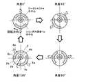
図6は、本発明の実施の形態1に係る圧縮要素の圧縮動作を示す説明図である。この図6は、図1のI−I線に沿った断面図である。以下、この図6を参照しながら、ロータ部4a(ロータシャフト4)の回転に伴い吸入室9、中間室10及び圧縮室11の容積が変化する様子を説明する。先ず、ロータシャフト4の回転に伴い、吸入管26から低圧の冷媒が吸入ポート1aに流入する。ここで、各空間(吸入室9、中間室10、圧縮室11)の容積変化を説明するにあたり、ロータ部4a(ロータシャフト4)の回転角度を次のように定義する。まず、第1のベーン部5とシリンダ1のシリンダ内周面1bとの摺動箇所(接触箇所)が最近接点32と一致する状態を、「角度0°」と定義する。図6では、「角度0°」、「角度45°」、「角度90°」、「角度135°」の状態において、第1のベーン部5及び第2のベーン部6の位置と、そのときの吸入室9、中間室10及び圧縮室11の状態を示している。 FIG. 6 is an explanatory diagram showing a compression operation of the compression element according to
なお、図6の「角度0°」の図に示す矢印は、ロータシャフト4の回転方向(図6では時計方向)である。但し、他の図では、ロータシャフト4の回転方向を示す矢印は省略している。また、図6において「角度180°」以降の状態を示していないのは、「角度180°」になると、「角度0°」において第1のベーン部5と第2のベーン部6が入れ替わった状態と同じになり、以降は「角度0°」から「角度135°」までと同じ圧縮動作となるためである。 The arrow shown in the “
図6における「角度0°」では、最近接点32と第2のベーン部6で仕切られた右側の空間は中間室10で、切欠き部1cを介して吸入ポート1aと連通しており、ガス(冷媒)を吸入する。最近接点32と第2のベーン部6で仕切られた左側の空間は、第1の吐出ポート1d及び第2の吐出ポート1eに連通した圧縮室11となる。 At “
図6における「角度45°」では、第1のベーン部5と最近接点32で仕切られた空間は、切欠き部1cを介して吸入ポート1aと連通している吸入室9となる。また、第1のベーン部5と第2のベーン部6で仕切られた空間は中間室10となる。この状態では、吸入室9及び中間室10が、切欠き部1cを介して吸入ポート1aと連通している。中間室10の容積は「角度0°」のときより大きくなるので、ガスの吸入を続ける。また、第2のベーン部6と最近接点32で仕切られた空間は圧縮室11で、圧縮室11の容積は「角度0°」のときより小さくなり、冷媒は圧縮され徐々にその圧力が高くなる。 At “
ここで、圧縮室11内の圧力が冷凍サイクルの高圧を上回ると、第1の吐出弁42及び第2の吐出弁44が開き、圧縮室11内のガスは、第1の吐出ポート1dから第1の吐出ポート2dを通って密閉容器103内に吐出されるとともに、第2の吐出ポート1eからも吐出空間41及び連通路2eを通って密閉容器103内に吐出される。密閉容器103内に吐出されたガスは、電動要素102を通過して密閉容器103の上部に固定(溶接)された吐出管24から外部(冷凍サイクルの高圧側)に吐出される(図1に実線で図示)。したがって、密閉容器103内の圧力は高圧である吐出圧力となる。なお、図6においては、「角度45°」において、圧縮室11内の圧力が高圧を上回った場合を示している。 Here, when the pressure in the
図6における「角度90°」では、第1のベーン部5のベーン先端部5bがシリンダ1のシリンダ内周面1b上の点Bと重なるので、中間室10は吸入ポート1aと連通しなくなる。これにより、中間室10でのガスの吸入は終了する。また、この状態で、中間室10の容積は略最大となる。吸入室9の容積は「角度45°」のときより大きくなり、吸入を続ける。圧縮室11の容積は「角度45°」のときより更に小さくなるので、圧縮室11内のガスは、第1の吐出ポート1dから第1の吐出ポート2dを通って密閉容器103内に吐出されるとともに、第2の吐出ポート1eからも吐出空間41及び連通路2eを通って密閉容器103内に吐出される。 At “angle 90 °” in FIG. 6, the
図6における「角度135°」では、中間室10の容積は「角度90°」ときより小さくなり、ガスの圧力は上昇する。また、吸入室9の容積は「角度90°」のときより大きくなり、吸入を続ける。ここで、第2のベーン部6のベーン6aは、第2の吐出ポート1eを通過しており、第2の吐出ポート1eは中間室10に開口するため、第2の吐出弁44は圧力差によって閉じる。一方、第1の吐出ポート1dは圧縮室11に開口したままなので、第1の吐出弁42は開いている。圧縮室11の容積は「角度90°」のときより更に小さくなるので、圧縮室11内のガスは、第1の吐出ポート1dから第1の吐出ポート2dを通って密閉容器103内に吐出されることとなる。 At “angle 135 °” in FIG. 6, the volume of the
その後、第2のベーン部6が第1の吐出ポート1dを通過すると、圧縮室11には高圧の冷媒が若干残る(ロスとなる)。そして、「角度180°」(図示せず)で、圧縮室11が消滅したとき、この高圧の冷媒は吸入室9にて低圧の冷媒に変化する。なお、「角度180°」では吸入室9が中間室10に移行し、中間室10が圧縮室11に移行して、以降圧縮動作を繰り返す。 Thereafter, when the
このように、ロータ部4a(ロータシャフト4)の回転により、吸入室9は徐々に容積が大きくなり、ガスの吸入を続ける。以後中間室10に移行するが、途中まで容積が徐々に大きくなり、更にガスの吸入を続ける。途中で、中間室10の容積は最大となり、吸入ポート1aに連通しなくなるので、ここでガスの吸入を終了する。以後、中間室10の容積は徐々に小さくなり、ガスを圧縮する。その後、中間室10は圧縮室11に移行して、ガスの圧縮を続ける。所定の圧力まで圧縮されたガスは、第1の吐出ポート1d及び第1の吐出ポート2dを通って第1の吐出弁42を押し上げて、密閉容器103内に吐出されるとともに、第2の吐出ポート1eからも、第2の吐出弁44を押し上げて吐出空間41及び連通路2eを通って密閉容器103内に吐出される。その後、第2のベーン部6のベーン6aが第2の吐出ポート1eを通過すると、第2の吐出弁44は閉じ、圧縮室11内の圧縮されたガスは第1の吐出ポート1d及び第1の吐出ポート2dからのみ密閉容器103内に吐出されることになる。 In this way, the volume of the
図7は、本発明の実施の形態1に係るベーンアライナの回転動作を説明するための説明図であり、図1のII−II線に沿った断面図である。なお、図7では、ベーンアライナ5c,6cの回転動作を示している。また、図7の「角度0°」の図に示す矢印は、ベーンアライナ5c,6cの回転方向(図7では時計方向)である。但し、他の図では、ベーンアライナ5c,6cの回転方向を示す矢印は省略している。 FIG. 7 is an explanatory diagram for explaining the rotation operation of the vane aligner according to the first embodiment of the present invention, and is a cross-sectional view taken along the line II-II of FIG. In addition, in FIG. 7, rotation operation | movement of the
ロータシャフト4の回転によって、第1のベーン部5のベーン5a及び第2のベーン部6のベーン6aがシリンダ1の中心軸周りに回転する(図6参照)。これにより、ベーンアライナ5c,6cは、図7に示すように、ベーンアライナ軸受部2bに支持されて、凹部2a内をシリンダ内周面1bの中心軸周りに回転する。なお、この動作は凹部3a内をベーンアライナ軸受部2bに支持されて回転するベーンアライナ5d,6dについても同様である。 By rotation of the
上記の冷媒圧縮動作においてロータシャフト4が回転することにより、図1に破線矢印で示すように、油ポンプ31によって油溜め104から冷凍機油25が吸い上げられ、給油路4hに送り出される。給油路4hに送り出された冷凍機油25は、給油路4iを通ってフレーム2の凹部2a、給油路4jを通ってシリンダヘッド3の凹部3aに送り出される。 As the
凹部2a,3aに送り出された冷凍機油25は、ベーンアライナ軸受部2b,3bを潤滑するとともに、その一部は凹部2a,3aと連通したベーン逃がし部4f,4gに供給される。ここで、密閉容器103内の圧力は高圧である吐出圧力になっているため、凹部2a,3a及びベーン逃がし部4f,4g内の圧力も吐出圧力となる。また、凹部2a,3aに送り出された冷凍機油25の一部は、フレーム2の主軸受部2c及びシリンダヘッド3の主軸受部3cに供給される。 The refrigerating
ベーン逃がし部4f,4gに送り出された冷凍機油25は、次のように流れることとなる。 The refrigerating
図8は、本発明の実施の形態1に係るベーン部のベーン近傍を示す要部拡大図である。なお、図8は、図4における第1のベーン部5のベーン5a近傍を示す要部拡大図となっており、図中に実線で示す矢印は冷凍機油25の流れを示している。 FIG. 8 is a main part enlarged view showing the vicinity of the vane of the vane part according to
上述のようにベーン逃がし部4fの圧力は吐出圧力であり、吸入室9及び中間室10の圧力より高いため、冷凍機油25は、ベーン5aの側面とブッシュ7間の摺動部を潤滑しながら、圧力差及び遠心力によって吸入室9及び中間室10に送り出される。また、冷凍機油25は、ブッシュ7とロータシャフト4のブッシュ保持部4d間の摺動部を潤滑しながら、圧力差及び遠心力によって吸入室9及び中間室10に送り出される。また、中間室10に送り出された冷凍機油25の一部は、ベーン先端部5bとシリンダ1のシリンダ内周面1b間の隙間をシールしながら吸入室9に流入する。 As described above, since the pressure of the
なお、図8では、第1のベーン部5で仕切られる空間が吸入室9と中間室10である場合について示したが、回転が進んで、第1のベーン部5で仕切られる空間が中間室10と圧縮室11となる場合でも同様である。また、圧縮室11内の圧力がベーン逃がし部4fの圧力と同じ吐出圧力に達した場合でも、遠心力によって、冷凍機油25は圧縮室11に向かって送り出されることになる。なお、以上の動作は第1のベーン部5に対して示したが、第2のベーン部6においても同様の動作を行う。 Although FIG. 8 shows the case where the space partitioned by the
上記の給油動作において、図1に示すように、主軸受部2cに供給された冷凍機油25は主軸受部2cの隙間を通ってフレーム2の上方の空間に吐き出された後、シリンダ1の外周部に設けた油戻し穴1fより、油溜め104に戻される。また、主軸受部3cに供給された冷凍機油25は主軸受部3cの隙間を通って油溜め104に戻される。また、ベーン逃がし部4f,4gを介して吸入室9、中間室10及び圧縮室11に送り出された冷凍機油25も、最終的にガスとともに第1の吐出ポート2d及び連通路2eからフレーム2の上方の空間に吐き出された後、シリンダ1の外周部に設けた油戻し穴1fより、油溜め104に戻される。また、油ポンプ31により給油路4hに送り出された冷凍機油25のうち、余剰な冷凍機油25はロータシャフト4の上方の排油穴4kから、フレーム2の上方の空間に吐き出された後、シリンダ1の外周部に設けた油戻し穴1fより、油溜め104に戻される。 In the above-described oil supply operation, as shown in FIG. 1, the refrigerating
本実施の形態1では以上に示したような動作を行うが、本実施の形態1に係るベーン型圧縮機200の効果が容易に理解できるように、圧縮室11からガスを吐出する動作について、本実施の形態1に係るベーン型圧縮機200と吐出ポートとして第1の吐出ポート1dのみしか備えていない一般的なベーン型圧縮機(例えば特許文献1に記載されているようなベーン型圧縮機)とを比較しながら説明する。 Although the operation as described above is performed in the first embodiment, the operation of discharging gas from the
まず、圧縮室11からガスを吐出する動作について、図6を用いて、吐出ポートとして第1の吐出ポート1dのみしか備えていない一般的なベーン型圧縮機(以下、本実施の形態1とは異なる構成の公知のベーン型圧縮機を単に一般的なベーン型圧縮機と称する)から説明する。図6からわかるように、第1の吐出ポート1dの位置における圧縮室11の流路幅(径方向の長さ)は極めて小さくなっており、流路面積も僅かである。そうすると、圧縮室11内のガスは、第1の吐出ポート1dに流入する前に流速が速くなり、第1の吐出ポート1dの大きさに関わらず、圧力損失が大きくなってしまう。 First, regarding the operation of discharging gas from the
一方、本実施の形態1に係るベーン型圧縮機200においては、第2の吐出ポート1eは、第1の吐出ポート1dよりも位相角度の小さい位置に設けられているので、第2の吐出ポート1eの位置における圧縮室11の流路幅(流路面積)は大きくなっている。このため、圧縮室11内のガスが第2の吐出ポート1eに流入する前の流速も遅くなるので、圧力損失を小さくすることができる。なお、第2のベーン部6が第2の吐出ポート1eを通過すると、図6の「角度135°」で示すように、圧縮室11に開口する吐出ポートは第1の吐出ポート1dのみとなる。しかしながら、この時点では、圧縮室11から吐出するガスの流量もかなり減少しているので、圧縮室11内のガスが第1の吐出ポート1dに流入する際の流速は大きくなく圧力損失も少ない。 On the other hand, in the
以上のように、第1の吐出ポート1dよりも位相角度の小さい位置に第2の吐出ポート1eを配することによって、一般的なベーン型圧縮機よりも吐出損失を小さくすることができる。 As described above, by disposing the
つぎに、圧縮室11からガスを吐出する動作において、第2のベーン部6が第2の吐出ポート1eを通過するときのガスの挙動について説明する。 Next, the behavior of the gas when the
図9は、ベーンが第2の吐出ポートを通過するときのガスの挙動を説明するための説明図である。この図9は、第2のベーン部6のベーン先端部6bが第2の吐出ポート1eの位置にあるときの第2のベーン部6のベーン6aまわりの要部断面図である。より詳しくは、図9(a)は、ベーン先端部6bの形状が本実施の形態1で示した形状(ベーン先端部6bの円弧形状の半径がシリンダ内周面1bの半径とほぼ同等の半径)となっている場合を示している。また、図9(b)は、ベーン先端部6bの形状が一般的なベーン型圧縮機(例えば特許文献1や特許文献2に記載されているベーン型圧縮機のように、ベーンがロータ部に形成されたベーン溝に摺動自在に設けられているもの)の形状となっている場合を示している。 FIG. 9 is an explanatory diagram for explaining the behavior of the gas when the vane passes through the second discharge port. FIG. 9 is a cross-sectional view of the main part around the
図9(a)に示すように、本実施の形態1に係るベーン型圧縮機200は、第2のベーン部6のベーン先端部6bの円弧形状の半径がシリンダ内周面1bの半径とほぼ同等の半径となっている。このため、第2のベーン部6のベーン先端部6bとシリンダ内周面1bとの間の隙間は、ベーン先端部6bの幅全体にわたって微小隙間δとなっている(式(1)参照)。一方、第2の吐出ポート1e(より詳しくはシリンダ内周面1bに形成された開口部)の周方向の幅は第2のベーン部6のベーン先端部6bの幅よりも小さくなっている。このため、第2のベーン部6が第2の吐出ポート1eを通過する場合でも、ベーン先端部6bとシリンダ内周面1bとの間の隙間はδのままである。したがって、ベーン先端部6bとシリンダ内周面1b間の隙間を通って圧縮室11から中間室10へ漏れるガスの量を極めて少なく抑えることができる。 As shown in FIG. 9A, in the
一方、図9(b)に示すように、ベーン先端部6bの形状が一般的なベーン型圧縮機の形状となっている場合、第2のベーン部6のベーン先端部6bの円弧形状の半径は、シリンダ内周面1bの半径よりもかなり小さく構成されている。このため、ベーン先端部6bとシリンダ内周面1bとの隙間は、ベーン先端部6bとシリンダ内周面1b間の接触位置51(シリンダ内周面1bの吐出ポート1eが設けられていない軸方向の箇所とベーン先端部6bとの接触位置)から離れるにしたがって大きくなる。このため、第2の吐出ポート1e(より詳しくはシリンダ内周面1bに形成された開口部)の周方向の幅を第2のベーン部6のベーン先端部6bの幅より小さく形成しても、図に破線で示すように、第2の吐出ポート1eを介して、圧縮室11から中間室10への漏れ経路ができる。したがって、ベーン先端部6bとシリンダ内周面1b間の隙間を通って圧縮室11から中間室10へ漏れるガスの量が増大することになる。 On the other hand, as shown in FIG. 9B, when the shape of the
上記のベーン先端部6bとシリンダ内周面1b間の隙間を通って圧縮室11から中間室10へ漏れるガスの量の差は、以下の理由によって生じるものである。つまり、特許文献1や特許文献2に記載されているような一般的なベーン型圧縮機の場合、ベーン先端部6b(及び5b)を構成する円弧形状の半径をシリンダ内周面1bの半径よりも小さく構成せざるを得ない。これは、特許文献1や特許文献2に記載されているような一般的なベーン型圧縮機においてはロータ部4aの中心とシリンダ内周面1bの中心が偏心しており、ベーンがロータ44aの中心を回転軸として回転しているためである。つまり、ベーン先端部6b(及び5b)の円弧形状部分とシリンダ内周面1bが常に摺動するためには、ベーン先端部6b(及び5b)の円弧形状の半径をシリンダ内周面1bの半径より小さくする必要があるためである。一方、本実施の形態1に係るベーン型圧縮機200においては、第1のベーン部5及び第2のベーン部6がシリンダ内周面1bの中心を回転軸として回転するように構成しているので(換言すると、ベーン先端部5b,6bの円弧形状の法線とシリンダ内周面1bの法線が常に略一致して圧縮動作を行うことができるので)、ベーン先端部6b(及び5b)の円弧形状の半径とシリンダ内周面1bの半径を同等または同等近くに設定することができる。 The difference in the amount of gas that leaks from the
以上、本実施の形態1に係るベーン型圧縮機200においては、第1のベーン部5及び第2のベーン部6が第2の吐出ポート1eを通過する際のガス漏れが増大することなく、圧力損失を低減することが可能なので、損失の極めて少ない高効率のベーン型圧縮機200を得ることができる。 As described above, in the
なお、本実施の形態1においては、第2の吐出ポート1e(より詳しくはシリンダ内周面1bに形成された開口部)の周方向の幅を第1のベーン部5のベーン先端部5bの幅及び第2のベーン部6のベーン先端部6bの幅よりも小さく形成したが、第2の吐出ポート1e(より詳しくはシリンダ内周面1bに形成された開口部)の周方向の幅は、第1のベーン部5のベーン先端部5bの幅及び第2のベーン部6のベーン先端部6bの幅と同等までは大きくすることが可能である。 In the first embodiment, the circumferential width of the
また、本実施の形態1では第1の吐出ポート1dの断面積と第2の吐出ポート1eの断面積との関係について特に言及しなかったが、例えば次のように構成してもよい。つまり、第2の吐出ポート1eに位置する圧縮室11の流路面積は、第1の吐出ポート1dに位置する圧縮室11の流路面積よりも大きいので、圧力損失を効果的に低減するためにはできるだけ第2の吐出ポート1eから吐出する流量を多くした方がよく、このためには第2の吐出ポート1eの断面積は第1の吐出ポート1dの断面積よりも大きくするとよい。 In the first embodiment, the relationship between the cross-sectional area of the
また、本実施の形態1では第2の吐出ポート1eを2つの冷媒流路で構成したが、これはあくまでも一例であり、第2の吐出ポート1eの構成は上記の構成に限定されるものではない。
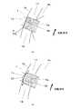
図10は、本実施の形態1に係るベーン型圧縮機の第2の吐出ポートの別の一例を示す説明図である。この図10は、図2及び図4における矢視A図である。
例えば図10に示すように、第2の吐出ポート1eを1つの冷媒流路で構成してもよい。また、第2の吐出ポート1eを3つ以上の冷媒流路で構成しても勿論よい。また、第2の吐出ポート1eの断面形状(第2の吐出ポート1eが複数の冷媒流路で形成されている場合は、各冷媒流路の断面形状)も長穴状に限定されるものではなく、周方向の幅が第1のベーン部5のベーン先端部5bの幅及び第2のベーン部6のベーン先端部6bの幅以下であれば任意の形状でよい。In the first embodiment, the
FIG. 10 is an explanatory diagram illustrating another example of the second discharge port of the vane compressor according to the first embodiment. FIG. 10 is a view A in FIG. 2 and FIG.
For example, as shown in FIG. 10, the
また、圧縮室11から第2の吐出ポートに流入したガスの流出先も上記の構成に限定されるものではない。例えば、第2の吐出ポート1eをシリンダ1の外周側に貫通しない構成とし、フレーム2及びシリンダヘッド3のうちの少なくとも一方に第2の吐出ポート1eと連通する貫通孔を形成し、この貫通孔から密閉容器103内へ、圧縮室11から第2の吐出ポートに流入したガスを流出させてもよい。この場合、この貫通孔の出口部に第2の吐出弁44及び第2の吐出弁押え45が設けられることとなる。このような構成でも上記と同様の動作で同様の効果が得られる。 Further, the outflow destination of the gas flowing into the second discharge port from the
また、第1の吐出ポートの構成も上記の構成に限定されるものではない。
図11は、本実施の形態1に係るベーン型圧縮機の第1の吐出ポートの別の一例を示す説明図である。この図11は、図1のI−I線に沿った断面図であり、図6における回転角度90°の状態を示している。
図11では、第1の吐出ポート1dを第2の吐出ポート1eと同様、シリンダ内周面1bに径方向に貫通した構成としている。このため、第1の吐出ポート1dの出口部に第1の吐出弁42及び第1の吐出弁押え43が取付けられている。このような構成でも上記と同様の動作で同様の効果が得られる。Further, the configuration of the first discharge port is not limited to the above configuration.
FIG. 11 is an explanatory diagram showing another example of the first discharge port of the vane compressor according to the first embodiment. FIG. 11 is a cross-sectional view taken along the line II in FIG. 1, and shows a state at a rotation angle of 90 ° in FIG.
In FIG. 11, the
また例えば、上述した第1のベーン部5及び第2のベーン部6においては、ベーン5a,6aのベーン長手方向とベーン先端部5b,6bの円弧の法線方向とが略同一方向となっていた。これに限らず、第1のベーン部5及び第2のベーン部6を例えば図12のように構成してもよい。 Further, for example, in the
図12は、本発明の実施の形態1に係る圧縮要素のベーンのさらに別の一例を示す平面図である。
図12において、Cは、ベーン5a,6aのベーン長手方向を示している。また、Dは、ベーン先端部5b,6bの円弧の法線方向を示している。つまり、ベーン5a,6aは、ベーンアライナ5c,5d,6c,6dに対して、Cの方向に傾けて設けられている。また、ベーン先端部5b,6bの円弧の法線Dは、ベーン長手方向Cに対して傾いており、ベーンアライナ5c,5d,6c,6dを形成する円弧形状部の中心を通るように形成されている。FIG. 12 is a plan view showing still another example of the vane of the compression element according to
In FIG. 12, C indicates the vane longitudinal direction of the
図12に示す構成においても、図13に示すように、ベーン先端部5b,6bの円弧とシリンダ1のシリンダ内周面1bの法線は回転中常に一致する状態で圧縮動作を行なうことが可能であるため、上記と同様の効果が得られる。また、ベーン先端部5b,6bの円弧長さ(つまり、ベーン先端部5b,6bの幅)を長くすることが可能となり、第2の吐出ポート1eの断面積及び圧縮室11側の開口部の周方向の幅をより大きくできるという効果も得られる。 Also in the configuration shown in FIG. 12, as shown in FIG. 13, the compression operation can be performed in a state where the arcs of the
実施の形態2.
実施の形態1では、第1の吐出ポート1dよりも位相角度の小さい位置に形成した吐出ポートが1つ(第2の吐出ポート1e)のみのベーン型圧縮機200について説明した。これに限らず、第1の吐出ポート1dよりも位相角度の小さい位置に複数の第2の吐出ポートを形成しても勿論よい。なお、本実施の形態2で特に記述しない項目については実施の形態1と同様とし、同一の機能や構成については同一の符号を用いて述べることとする。
In the first embodiment, the
図14は、本実施の形態2に係るベーン型圧縮機の圧縮要素を示す断面図である。この図14は、図1のI−I線に沿った断面図であり、図6における回転角度90°の状態を示している。
図14に示すように、本実施の形態2に係るベーン型圧縮機200は、2つの第2の吐出ポート(第2の吐出ポート1e,第2の吐出ポート1g)を備えている。つまり、本実施の形態2に係るベーン型圧縮機200は、実施の形態1で示したベーン型圧縮機200の構成に、第2の吐出ポート1gを加えたものとなっている。この第2の吐出ポート1gは第2の吐出ポート1eよりも位相角度の小さい位置に径方向に貫通して設けられており、第2の吐出ポート1gの周方向の幅は第1のベーン部5のベーン先端部5bの幅及び第2のベーン部6のベーン先端部6bの幅よりも小さくなっている。また、第2の吐出ポート1gの出口部には、第3の吐出弁46及び第3の吐出弁46の開度を規制するための第3の吐出弁押え47が取付けられている。本実施の形態2においては、第2の吐出ポート1gを第2の吐出ポート1eよりも位相角度の小さい位置に設けたので、第2の吐出ポート1gの位置における圧縮室11の流路幅(流路面積)は第2の吐出ポート1eの位置における圧縮室11の流路幅(流路面積)よりもさらに大きくなっている。FIG. 14 is a cross-sectional view showing a compression element of the vane type compressor according to the second embodiment. 14 is a cross-sectional view taken along the line II of FIG. 1, and shows a state at a rotation angle of 90 ° in FIG.
As shown in FIG. 14, the
図15は、本発明の実施の形態2に係る圧縮要素の圧縮動作を示す説明図であり、図1のI−I線に沿った断面図である。以下、この図15を参照しながら、圧縮室11からのガスの吐出動作を説明する。 FIG. 15 is an explanatory view showing the compression operation of the compression element according to
図15における「角度45°」において、圧縮室11内の圧力が冷凍サイクルの高圧を上回ると、第1の吐出弁42、第2の吐出弁44及び第3の吐出弁46が開く。そして、圧縮室11内のガスは、第1の吐出ポート1d、第2の吐出ポート1e及び第2の吐出ポート1gから吐出空間41へ流出し、さらに連通路2eを通って密閉容器103内に吐出される。なお、図15においては、「角度45°」において、圧縮室11内の圧力が高圧を上回った場合を示している。 When the pressure in the
図15における「角度90°」では、第2のベーン部6は、第2の吐出ポート1gを通過しており、第2の吐出ポート1gは中間室10に開口するため、第3の吐出弁46は圧力差によって閉じる。一方、第1の吐出ポート1d及び第2の吐出ポート1eは圧縮室11に開口しているので、第1の吐出ポート1d及び第2の吐出ポート1eから圧縮室11内のガスが吐出される。 At “angle 90 °” in FIG. 15, the
図15における「角度135°」では、第2のベーン部6は、第2の吐出ポート1eを通過しており、第2の吐出ポート1eは中間室10に開口するため、第2の吐出弁44は圧力差によって閉じる。一方、第1の吐出ポート1dは圧縮室11に開口しているので、第1の吐出ポート1dから圧縮室11内のガスが吐出される。 At the “angle 135 °” in FIG. 15, the
以上、本実施の形態2のように構成されたベーン型圧縮機200においては、第2の吐出ポート1gの位置における圧縮室11の流路面積は第2の吐出ポート1eの位置における圧縮室11の流路面積よりも大きいので、圧縮室11内のガスが第2の吐出ポート1gに流入する前の流速は実施の形態1よりも遅くなる。このため、圧力損失をより小さくすることができる。なお、第2のベーン部6が第2の吐出ポート1gを通過すると、図15の「角度90°」で示すように、圧縮室11に開口する吐出ポートは第1の吐出ポート1dと第2の吐出ポート1eになるが、この時点では、圧縮室11から吐出するガス流量もある程度減少しているので、圧縮室11内のガスが第2の吐出ポート1eに流入する際の流速を実施の形態1よりもより遅くでき、圧力損失もより少なくできる。 As described above, in the
なお、実施の形態2では第1の吐出ポート1d、第2の吐出ポート1e及び第2の吐出ポート1eの断面積について特に言及しなかったが、例えば次のように構成してもよい。つまり、第2の吐出ポート1gに位置する圧縮室11の流路面積は、第2の吐出ポート1eに位置する圧縮室11の流路面積よりも大きく、第2の吐出ポート1eに位置する圧縮室11の流路面積は、第1の吐出ポート1dに位置する圧縮室11の流路面積よりも大きい。このため、圧力損失を効果的に低減するためには、断面積の小さい方から第1の吐出ポート1d、第2の吐出ポート1e、第2の吐出ポート1gとするのがよい。つまり、圧力損失を効果的に低減するためには、位相角度の小さい吐出ポートほど、断面積を大きくするとよい。 In the second embodiment, no particular reference is made to the cross-sectional areas of the
また、本実施の形態2では位相角度が異なる第2の吐出ポートを2つ(第2の吐出ポート1e,第2の吐出ポート1g)備えたベーン型圧縮機200について説明したが、それぞれ位相角度が異なる第2の吐出ポートを3つ以上備えても勿論よい。この場合、圧力損失を効果的に低減するためには、位相角度の小さい吐出ポートほど、断面積を大きくするとよい。 In the second embodiment, the
実施の形態3.
実施の形態1及び実施の形態2では、第2の吐出ポートの圧縮室11側開口部がシリンダ内周面1bに開口していた。これに限らず、第2の吐出ポートの圧縮室11側開口部が次のような位置に開口していてもよい。なお、本実施の形態3において、特に記述しない項目については実施の形態1又は実施の形態2と同様とし、同一の機能や構成については同一の符号を用いて述べることとする。
In the first embodiment and the second embodiment, the
図16は、本実施の形態3に係るベーン型圧縮機の圧縮要素を示す断面図である。この図16は、図1のI−I線に沿った断面図であり、図6における回転角度90°の状態を示している。また、図17は、図16のIII−III線に沿った断面図である。
以下、これら図16及び図17を用いて、本実施の形態3に係るベーン型圧縮機200について説明する。FIG. 16 is a cross-sectional view showing a compression element of the vane type compressor according to the third embodiment. FIG. 16 is a cross-sectional view taken along the line II of FIG. 1, and shows a state at a rotation angle of 90 ° in FIG. FIG. 17 is a sectional view taken along line III-III in FIG.
Hereinafter, the
図16及び図17に示すように、本実施の形態3に係るベーン型圧縮機200においては、第2の吐出ポート2fが、フレーム2に軸方向に貫通して設けられており、周方向の幅は第1のベーン部5のベーン5a及び第2のベーン部6のベーン6aの幅よりも小さくなっている。そして、第2の吐出ポート2fの出口部には、第2の吐出弁44及び第2の吐出弁押え45が取付けられている。 As shown in FIGS. 16 and 17, in the
本実施の形態3に係るベーン型圧縮機200の圧縮室11からガスが吐出する動作は、実施の形態1と同様である。また、第1のベーン部5または第2のベーン部6が第2の吐出ポート2fを通過するときのガスの挙動は次のようになる。
図17に示すように、第2の吐出ポート2fの周方向の幅はベーン6aの幅よりも小さくなっているので、第2のベーン部6が第2の吐出ポート2fの位置にあるとき、第2の吐出ポート2fを介しての圧縮室11から中間室10へのガスの漏れは、ベーン6aの端面とフレーム2の端面でシールされる。このため、実施の形態1と同様、圧縮室11から中間室10への漏れを極めて少なく抑えることができる。The operation of discharging gas from the
As shown in FIG. 17, since the circumferential width of the
以上から、本実施の形態3のように構成されたベーン型圧縮機200においては、実施の形態1及び実施の形態2と同様に、第1のベーン部5及び第2のベーン部6が第2の吐出ポート2fを通過する際の漏れが増大することなく、圧力損失を低減することが可能なので、損失の極めて少ない高効率のベーン型圧縮機200を得ることができる。 From the above, in the
また、本実施の形態3に係るベーン型圧縮機200は、第2の吐出ポート2fをフレーム2に形成したので(つまり、第2の吐出ポート2fの圧縮室11側の開口部がフレーム2に開口しているので)、次のような効果を得ることもできる。つまり、実施の形態1及び実施の形態2では、第2の吐出ポート(第2の吐出ポート1eや第2の吐出ポート1g)の圧縮室11側の開口部がシリンダ内周面1bに開口していたので、ベーン先端部5b,6bの円弧形状の半径とシリンダ内周面1bの半径を同等に設定する必要がある。このため、第1のベーン部5、第2のベーン部6をシリンダ内周面1bの中心まわりに回転するように(換言すると、ベーン先端部5b,6bの円弧形状の法線とシリンダ内周面1bの法線が常に略一致して圧縮動作を行うように)、ベーン角度調整手段を設ける必要があった。しかしながら、本実施の形態3では、図17から明らかなように、第2の吐出ポート2fを介する圧縮室11から中間室10へのガスの漏れは第1のベーン部5及び第2のベーン部6の端面とフレーム2間でシールされるため、特許文献1に記載されているような一般的なベーン型圧縮機にも適用可能である。 In the
なお、本実施の形態3では、第2の吐出ポート2fをフレーム2に設けたが、シリンダヘッド3に設けてもよく、フレーム2とシリンダヘッド3の両方に設けてもよい。 In the third embodiment, the
また、本実施の形態3においては、第2の吐出ポート2f(より詳しくは圧縮室11側の開口部)の周方向の幅を第1のベーン部5のベーン5aの幅及び第2のベーン部6のベーン6aの幅よりも小さく形成したが、第2の吐出ポート2f(より詳しくは圧縮室11側の開口部)の周方向の幅は、第1のベーン部5のベーン5aの幅及び第2のベーン部6のベーン6aの幅と同等までは大きくすることが可能である。 In the third embodiment, the circumferential width of the
また、実施の形態3においても、実施の形態2と同様、第2の吐出ポートを2つ設けてもよく、第2の吐出ポートを3つ以上設けても勿論よい。 Also in the third embodiment, as in the second embodiment, two second discharge ports may be provided, and of course, three or more second discharge ports may be provided.
以上、上記の実施の形態1〜実施の形態3では、ベーン枚数が2枚の場合について示したが、ベーン枚数が1枚の場合でも3枚以上の場合でも同様の構成であり、同様の効果が得られる。ベーン枚数が1枚の場合、ベーンアライナを、部分リング形状ではなく、リング形状に形成してもよい。 As described above, in the above-described first to third embodiments, the case where the number of vanes is two has been described. However, the configuration is the same regardless of whether the number of vanes is one or three or more, and similar effects are obtained. Is obtained. When the number of vanes is one, the vane aligner may be formed in a ring shape instead of a partial ring shape.
また、上記の実施の形態1〜実施の形態3ではロータシャフト4の遠心力を利用した油ポンプ31について示したが、油ポンプの形態はいずれでもよく、例えば特開2009−62820号公報に記載の容積形ポンプを油ポンプ31として用いてもよい。 In the first to third embodiments, the
また、上記の実施の形態1〜実施の形態3で説明したベーン角度調整手段は一例であり、ベーン角度調整手段はこの構成に限定されるものではない。公知のベーン角度調整手段を用いて本発明を実施することも可能であり、例えば特開2000−352390号公報に記載のベーン型圧縮機のように、ロータ部の内部を中空にし、その中にベーンをシリンダの内周面の中心にて回転可能に支持する固定軸を配置し、ベーンがロータ部に対して揺動可能となるようにロータ部の外周部近傍でブッシュを介してベーンを保持する構成としてもよい。このようなベーン角度調整手段においても、ベーンはシリンダの内周面の中心まわりに回転することになるので、ベーン先端部の円弧形状の半径とシリンダ内周面の半径を同等に設定することができ、実施の形態1及び実施の形態2に示した動作と同様の動作で、同様の効果が得られる。 The vane angle adjusting means described in the first to third embodiments is an example, and the vane angle adjusting means is not limited to this configuration. It is also possible to carry out the present invention using a known vane angle adjusting means. For example, as in a vane type compressor described in Japanese Patent Application Laid-Open No. 2000-352390, the interior of the rotor portion is made hollow, A fixed shaft that rotatably supports the vane at the center of the inner peripheral surface of the cylinder is disposed, and the vane is held via a bush in the vicinity of the outer peripheral portion of the rotor portion so that the vane can swing relative to the rotor portion. It is good also as composition to do. Even in such a vane angle adjusting means, the vane rotates around the center of the inner peripheral surface of the cylinder, so the radius of the arc shape of the tip of the vane and the radius of the inner peripheral surface of the cylinder can be set equal. The same effect can be obtained by the same operation as the operation shown in the first and second embodiments.
また、上記の実施の形態2及び実施の形態3では、複数の第2の吐出ポートを設ける際に全ての第2の吐出ポートを同一部材に形成したが、第2の吐出ポートの形成位置はこれに限定されるものではない。例えば第2の吐出ポートの一部を、その圧縮室11側の開口部がシリンダ内周面1bに開口するものとしてもよい(例えば、実施の形態2の構成)。そして、残りの第2の吐出ポートを、その圧縮室11側の開口部がフレーム2及びシリンダヘッド3のうちの少なくとも一方に開口するものとしてもよい。 In the second embodiment and the third embodiment, when the plurality of second discharge ports are provided, all the second discharge ports are formed on the same member. It is not limited to this. For example, a part of the second discharge port may have an opening on the
また、上記の実施の形態1〜実施の形態3では、ベーン5aとベーンアライナ5c,5dとを一体で形成し、ベーン6aとベーンアライナ6c,6dとを一体で形成した。しかしながら、ベーン5a,6aの長手方向とベーンアライナ5c,5d,6c,6fの外周面の法線とが一定の角度を保てる構成となっていれば、これらを別体で形成しても勿論よい。例えば図18に示すように、ベーン5a,6aに相当するベーン105と、ベーンアライナ5c,5d,6c,6dに相当するベーンアライナ106とを別々に形成すればよい。そして、ベーン105の凸部105aをベーンアライナ106の凹部106aに挿入し、ベーン105とベーンアライナ106とを一体に取り付けてもよい。このとき、ベーンアライナ106に対してベーン105がその長手方向に摺動自在となるように両者を接続してもよい。 In the first to third embodiments, the
1 シリンダ、1a 吸入ポート、1b シリンダ内周面、1c 切欠き部、1d 第1の吐出ポート、1e 第2の吐出ポート、1f 油戻し穴、1g 第2の吐出ポート、2 フレーム、2a 凹部、2b ベーンアライナ軸受部、2c 主軸受部、2d 第1の吐出ポート、2e 連通路、2f 第2の吐出ポート、3 シリンダヘッド、3a 凹部、3b ベーンアライナ軸受部、3c 主軸受部、4 ロータシャフト、4a ロータ部、4b 回転軸部、4c 回転軸部、4d ブッシュ保持部、4e ブッシュ保持部、4f ベーン逃がし部、4g ベーン逃がし部、4h 給油路、4i 給油路、4j 給油路、4k 排油穴、5 第1のベーン部、5a ベーン、5b ベーン先端部、5c ベーンアライナ、5d ベーンアライナ、6 第2のベーン部、6a ベーン、6b ベーン先端部、6c ベーンアライナ、6d ベーンアライナ、7 ブッシュ、7a ブッシュ中心、8 ブッシュ、8a ブッシュ中心、9 吸入室、10 中間室、11 圧縮室、21 固定子、22 回転子、23 ガラス端子、24 吐出管、25 冷凍機油、26 吸入管、31 油ポンプ、32 最近接点、41 吐出空間、42 第1の吐出弁、43 第1の吐出弁押え、44 第2の吐出弁、45 第2の吐出弁押え、46 第3の吐出弁、47 第3の吐出弁押え、51 接触位置、101 圧縮要素、102 電動要素、103 密閉容器、104 油溜め、105 ベーン、105a 凸部、106 ベーンアライナ、106a 凹部、200 ベーン型圧縮機。 1 cylinder, 1a suction port, 1b cylinder inner peripheral surface, 1c notch, 1d first discharge port, 1e second discharge port, 1f oil return hole, 1g second discharge port, 2 frame, 2a recess, 2b Vane aligner bearing part, 2c main bearing part, 2d first discharge port, 2e communication path, 2f second discharge port, 3 cylinder head, 3a recess, 3b vane aligner bearing part, 3c main bearing part, 4 rotor shaft 4a Rotor part, 4b Rotating shaft part, 4c Rotating shaft part, 4d Bush holding part, 4e Bush holding part, 4f Vane relief part, 4g Vane relief part, 4h Oil supply path, 4i Oil supply path, 4j Oil supply path, 4k Oil exhaust Hole 5 first vane portion 5a vane 5b vane tip 5c vane aligner 5d vane aligner 6 second vane 6a vane, 6b vane tip, 6c vane aligner, 6d vane aligner, 7 bush, 7a bush center, 8 bush, 8a bush center, 9 suction chamber, 10 intermediate chamber, 11 compression chamber, 21 stator, 22 rotations 23, glass terminal, 24 discharge pipe, 25 refrigerating machine oil, 26 suction pipe, 31 oil pump, 32 nearest point, 41 discharge space, 42 first discharge valve, 43 first discharge valve presser, 44 second discharge Valve, 45 Second discharge valve presser, 46 Third discharge valve, 47 Third discharge valve presser, 51 Contact position, 101 Compression element, 102 Electric element, 103 Airtight container, 104 Oil sump, 105 Vane, 105a Convex Section, 106 vane aligner, 106a recess, 200 vane compressor.
Claims (10)
Translated fromJapanese前記穴の一方の開口を塞ぐシリンダヘッドと、
前記穴の他方の開口を塞ぐフレームと、
前記シリンダの内部において前記内周面の中心軸とずれた回転軸を中心に回転運動する円柱形のロータ部と、
前記ロータ部に回転力を伝達する回転軸部と、
前記ロータ部内に設置され、前記シリンダの内周面の中心周りに回転するように保持され、前記シリンダと前記ロータ部間に形成された圧縮空間を少なくとも吸入空間と吐出空間に仕切るベーンと、
を備えたベーン型圧縮機において、
前記フレーム及び前記シリンダヘッドの前記シリンダ側端面に、外周面が前記シリンダの前記内周面と同心となる凹部またはリング状の溝が形成され、
前記外周面に沿って摺動自在に回転し、前記ベーンの先端部と前記シリンダの内周面との間に隙間を保つように、前記ベーンに対して相対回転不能かつ相対移動不能に前記ベーンと一体に取り付けられ、あるいは前記ベーンと一体で形成されて前記ベーンを支持する部分リング形状のベーンアライナを備え、
前記圧縮空間に連通し、前記圧縮空間で圧縮されたガスを吐出する第1の吐出ポートと、前記第1の吐出ポートよりも圧縮行程の上流側となる位置に、前記圧縮空間に連通する第2の吐出ポートを設け、
該第2の吐出ポートにおける前記圧縮空間側の開口部の幅が前記ベーンの幅以下となっていることを特徴とするベーン型圧縮機。A cylinder having a cylindrical inner peripheral surface and holes opened at both ends;
A cylinder head that closes one opening of the hole;
A frame for closing the other opening of the hole;
A cylindrical rotor portion that rotates around a rotation axis that is shifted from the center axis of the inner peripheral surface in the cylinder;
A rotating shaft portion for transmitting a rotational force to the rotor portion;
A vane that is installed in the rotor portion, is held so as to rotate around the center of the inner peripheral surface of the cylinder, and divides a compression space formed between the cylinder and the rotor portion into at least a suction space and a discharge space;
In a vane compressor equipped with
A recess or ring-shaped groove whose outer peripheral surface is concentric with the inner peripheral surface of the cylinder is formed on the cylinder side end surface of the frame and the cylinder head,
The vane is slidably rotated along the outer peripheral surface, and thevane is relatively non-rotatable and non-movable relative to the vane so as to maintain a gap between the tip of the vane and the inner peripheral surface of the cylinder. Or a partial ring-shaped vane aligner that is formed integrally with the vane and supports the vane.
A first discharge port that communicates with the compression space and discharges the gas compressed in the compression space, and a first discharge port that communicates with the compression space at a position upstream of the first discharge port in the compression stroke. 2 discharge ports,
The vane type compressor, wherein a width of the opening on the compression space side in the second discharge port is equal to or less than a width of the vane.
該第2の吐出ポートにおける前記圧縮空間側の開口部は、周方向の幅が前記ベーンの先端部の幅以下となっていることを特徴とする請求項1に記載のベーン型圧縮機。The second discharge port is provided to be opened in the inner peripheral surface of the cylinder;
2. The vane compressor according to claim 1, wherein the opening on the compression space side of the second discharge port has a circumferential width equal to or less than a width of a tip of the vane.
該第2の吐出ポートにおける前記圧縮空間側の開口部は、周方向の幅が前記ベーンの幅以下となっていることを特徴とする請求項1に記載のベーン型圧縮機。The second discharge port is provided to be opened in at least one of the frame and the cylinder head,
2. The vane compressor according to claim 1, wherein the opening on the compression space side of the second discharge port has a circumferential width equal to or less than the width of the vane.
前記シリンダの前記内周面に開口部を有する前記第2の吐出ポートの当該開口部は、周方向の幅が前記ベーンの先端部の幅以下となっており、
前記フレーム及び前記シリンダヘッドのうちの少なくとも一方に開口部を有する前記第2の吐出ポートの当該開口部は、周方向の幅が前記ベーンの幅以下となっていることを特徴とする請求項1に記載のベーン型圧縮機。The second discharge port is provided in an opening at a position where the phase angle is different from at least one of the frame and the cylinder head and the inner peripheral surface of the cylinder.
The opening of the second discharge port having an opening on the inner peripheral surface of the cylinder has a circumferential width equal to or less than the width of the tip of the vane,
2. The opening of the second discharge port having an opening in at least one of the frame and the cylinder head has a circumferential width equal to or less than the width of the vane. The vane type compressor described in 1.
Priority Applications (1)
| Application Number | Priority Date | Filing Date | Title |
|---|---|---|---|
| JP2013553219AJP5774134B2 (en) | 2012-01-11 | 2012-12-12 | Vane type compressor |
Applications Claiming Priority (4)
| Application Number | Priority Date | Filing Date | Title |
|---|---|---|---|
| JP2012003257 | 2012-01-11 | ||
| JP2012003257 | 2012-01-11 | ||
| JP2013553219AJP5774134B2 (en) | 2012-01-11 | 2012-12-12 | Vane type compressor |
| PCT/JP2012/082143WO2013105386A1 (en) | 2012-01-11 | 2012-12-12 | Vane-type compressor |
Publications (2)
| Publication Number | Publication Date |
|---|---|
| JPWO2013105386A1 JPWO2013105386A1 (en) | 2015-05-11 |
| JP5774134B2true JP5774134B2 (en) | 2015-09-02 |
Family
ID=48781346
Family Applications (1)
| Application Number | Title | Priority Date | Filing Date |
|---|---|---|---|
| JP2013553219AActiveJP5774134B2 (en) | 2012-01-11 | 2012-12-12 | Vane type compressor |
Country Status (5)
| Country | Link |
|---|---|
| US (1) | US9388807B2 (en) |
| EP (1) | EP2803863B1 (en) |
| JP (1) | JP5774134B2 (en) |
| CN (1) | CN103930677B (en) |
| WO (1) | WO2013105386A1 (en) |
Families Citing this family (9)
| Publication number | Priority date | Publication date | Assignee | Title |
|---|---|---|---|---|
| US10739046B2 (en)* | 2014-06-17 | 2020-08-11 | Mitsubishi Electric Corporation | Compressor, refrigeration cycle apparatus, and air conditioner |
| KR102243681B1 (en)* | 2014-08-13 | 2021-04-23 | 엘지전자 주식회사 | Scroll Compressor |
| EP3475573B1 (en)* | 2016-06-22 | 2020-08-05 | Pierburg Pump Technology GmbH | Motor vehicle vacuum pump arrangement |
| CN106401967B (en)* | 2016-10-17 | 2019-03-19 | 珠海格力节能环保制冷技术研究中心有限公司 | Rotary compressor |
| EP3315782A1 (en)* | 2016-10-25 | 2018-05-02 | Entecnia Consulting, S.L.U. | Vacuum pump |
| KR20190132020A (en)* | 2018-05-18 | 2019-11-27 | 현대자동차주식회사 | Oil pump of vehicle having inner ring |
| KR102227090B1 (en)* | 2019-02-22 | 2021-03-12 | 엘지전자 주식회사 | Vain rotary compressor |
| KR102191124B1 (en) | 2019-02-28 | 2020-12-15 | 엘지전자 주식회사 | Vain rotary compressor |
| CN110863990B (en)* | 2019-11-19 | 2021-06-04 | 珠海格力节能环保制冷技术研究中心有限公司 | Compressor and air conditioner |
Family Cites Families (41)
| Publication number | Priority date | Publication date | Assignee | Title |
|---|---|---|---|---|
| GB191026718A (en) | 1910-11-17 | 1911-08-17 | Albert Bertram Lunn | Improvements in or relating to Means for Separating and Supporting the Bows of Cape-cart Hoods and the like. |
| US1291618A (en) | 1916-09-11 | 1919-01-14 | Willard M Mcewen | Combined fluid pump and motor. |
| US1339723A (en) | 1916-10-12 | 1920-05-11 | Walter J Piatt | Rotary pump |
| US1444269A (en) | 1920-11-01 | 1923-02-06 | Walter J Piatt | Rotary pump |
| GB244181A (en) | 1924-09-13 | 1925-12-14 | William Joe Stern | Improvements in and connected with rotary pump machines |
| US2044873A (en) | 1933-11-21 | 1936-06-23 | Cecil J Beust | Rotary compressor |
| CH181039A (en) | 1935-01-28 | 1935-11-30 | Rotorkompressoren A G | Rotary compressor with a cylindrical rotor mounted on both sides in a housing with a cylindrical bore eccentrically to the cylinder axis. |
| DE874944C (en) | 1951-02-17 | 1953-04-27 | Heinz Knebel | Rotary compressor |
| JPS5148883B2 (en)* | 1973-04-18 | 1976-12-23 | ||
| JPS51128704A (en) | 1975-05-02 | 1976-11-09 | Toyota Motor Corp | Rotary vane pump |
| JPS5260911A (en) | 1975-11-14 | 1977-05-19 | Hitachi Ltd | Pumping motor |
| JPS5629001A (en) | 1979-08-18 | 1981-03-23 | Masaichi Hashino | Rotary piston mechanism |
| JPS6137834Y2 (en)* | 1979-12-14 | 1986-11-01 | ||
| JPS5690490A (en) | 1979-12-19 | 1981-07-22 | Fujitsu Ltd | Memory change-over control system |
| JPS56129795A (en) | 1980-03-12 | 1981-10-12 | Nippon Soken Inc | Rotary compressor |
| JPS56150886U (en)* | 1980-04-14 | 1981-11-12 | ||
| JPS56150886A (en) | 1980-04-23 | 1981-11-21 | Nippon Telegr & Teleph Corp <Ntt> | Oscillating frequency stabilized semiconductor laser device |
| JPS5867996A (en) | 1981-10-20 | 1983-04-22 | Sanyo Electric Co Ltd | Blower unit |
| JPS5870087A (en) | 1981-10-21 | 1983-04-26 | Kishino Masahide | Rotary piston compressor having vanes rotating concentrically with inner wall surface of cylinder |
| JPS5867996U (en)* | 1981-11-02 | 1983-05-09 | 日産自動車株式会社 | rotary vane compressor |
| JPS601389A (en)* | 1983-06-16 | 1985-01-07 | Toyoda Autom Loom Works Ltd | Low-discharge-pulsation compressor |
| DE8434465U1 (en) | 1984-11-24 | 1986-03-27 | Robert Bosch Gmbh, 7000 Stuttgart | Vane sealing in vane pumps |
| US4958995A (en) | 1986-07-22 | 1990-09-25 | Eagle Industry Co., Ltd. | Vane pump with annular recesses to control vane extension |
| JPS63131883A (en) | 1986-11-21 | 1988-06-03 | Eagle Ind Co Ltd | Vane pump |
| JPS6373593U (en)* | 1986-11-04 | 1988-05-17 | ||
| JPS6373593A (en) | 1986-09-16 | 1988-04-04 | 日立化成工業株式会社 | Manufacture of ceramic multilayer interconnection board |
| US5087183A (en) | 1990-06-07 | 1992-02-11 | Edwards Thomas C | Rotary vane machine with simplified anti-friction positive bi-axial vane motion control |
| JP2812022B2 (en) | 1991-11-12 | 1998-10-15 | 松下電器産業株式会社 | Multi-stage gas compressor with bypass valve device |
| US5536153A (en)* | 1994-06-28 | 1996-07-16 | Edwards; Thomas C. | Non-contact vane-type fluid displacement machine with lubricant separator and sump arrangement |
| JPH08247063A (en) | 1995-03-07 | 1996-09-24 | Daikin Ind Ltd | Swing piston type compressor |
| JPH08247064A (en) | 1995-03-07 | 1996-09-24 | Daikin Ind Ltd | Swing piston type compressor |
| US6026649A (en) | 1996-04-11 | 2000-02-22 | Matsushita Electric Industrial Co., Ltd. | Compressor provided with refrigerant and lubricant in specified relationship |
| TW385332B (en) | 1997-02-27 | 2000-03-21 | Idemitsu Kosan Co | Refrigerating oil composition |
| JP2000352390A (en)* | 1999-06-08 | 2000-12-19 | Hiroyoshi Ooka | Axially supported vane rotary compressor |
| JP2007309281A (en) | 2006-05-22 | 2007-11-29 | Matsushita Electric Ind Co Ltd | Vane rotary compressor |
| JP2008014227A (en)* | 2006-07-06 | 2008-01-24 | Calsonic Compressor Inc | Gas compressor |
| JP2009062820A (en) | 2007-09-04 | 2009-03-26 | Mitsubishi Electric Corp | Hermetic rotary compressor |
| JP5025556B2 (en)* | 2008-04-23 | 2012-09-12 | 三菱電機株式会社 | Refrigerant compressor |
| JP5431805B2 (en) | 2009-06-24 | 2014-03-05 | 富士フイルム株式会社 | Composition, compound and film forming method |
| JP5366856B2 (en)* | 2010-02-17 | 2013-12-11 | 三菱電機株式会社 | Vane rotary type fluid apparatus and compressor |
| JP5637755B2 (en) | 2010-07-12 | 2014-12-10 | 三菱電機株式会社 | Vane type compressor |
- 2012
- 2012-12-12USUS14/350,989patent/US9388807B2/ennot_activeExpired - Fee Related
- 2012-12-12EPEP12865289.8Apatent/EP2803863B1/ennot_activeNot-in-force
- 2012-12-12JPJP2013553219Apatent/JP5774134B2/enactiveActive
- 2012-12-12CNCN201280055578.6Apatent/CN103930677B/enactiveActive
- 2012-12-12WOPCT/JP2012/082143patent/WO2013105386A1/enactiveApplication Filing
Also Published As
| Publication number | Publication date |
|---|---|
| WO2013105386A1 (en) | 2013-07-18 |
| US20140286807A1 (en) | 2014-09-25 |
| EP2803863A4 (en) | 2015-09-16 |
| JPWO2013105386A1 (en) | 2015-05-11 |
| US9388807B2 (en) | 2016-07-12 |
| EP2803863B1 (en) | 2019-04-03 |
| CN103930677A (en) | 2014-07-16 |
| EP2803863A1 (en) | 2014-11-19 |
| CN103930677B (en) | 2016-08-24 |
Similar Documents
| Publication | Publication Date | Title |
|---|---|---|
| JP5774134B2 (en) | Vane type compressor | |
| US20060153723A1 (en) | Rotary fluid machinery | |
| WO2013105129A1 (en) | Vane-type compressor | |
| KR101423009B1 (en) | Vane compressor | |
| US8366424B2 (en) | Rotary fluid machine with reverse moment generating mechanism | |
| JP5777733B2 (en) | Vane type compressor | |
| KR102310348B1 (en) | Rotary comppresor | |
| JP5932608B2 (en) | Vane type compressor | |
| JP6099550B2 (en) | Vane type two-stage compressor | |
| WO2009090888A1 (en) | Rotary fluid machine | |
| JP5921456B2 (en) | Vane type compressor | |
| JP5878911B2 (en) | Gas compressor | |
| JP2013072362A (en) | Compressor | |
| JP2013142351A (en) | Vane type compressor | |
| JP5932675B2 (en) | Vane type compressor | |
| JP5661204B2 (en) | Vane type compressor | |
| JP6017023B2 (en) | Vane type compressor | |
| JP5661203B2 (en) | Vane type compressor | |
| WO2015049905A1 (en) | Vane-type compressor | |
| JP5595600B2 (en) | Vane type compressor | |
| JP2007211672A (en) | Rotary compressor | |
| JP2014025408A (en) | Rotary compressor |
Legal Events
| Date | Code | Title | Description |
|---|---|---|---|
| TRDD | Decision of grant or rejection written | ||
| A01 | Written decision to grant a patent or to grant a registration (utility model) | Free format text:JAPANESE INTERMEDIATE CODE: A01 Effective date:20150602 | |
| A61 | First payment of annual fees (during grant procedure) | Free format text:JAPANESE INTERMEDIATE CODE: A61 Effective date:20150630 | |
| R150 | Certificate of patent or registration of utility model | Ref document number:5774134 Country of ref document:JP Free format text:JAPANESE INTERMEDIATE CODE: R150 | |
| R250 | Receipt of annual fees | Free format text:JAPANESE INTERMEDIATE CODE: R250 | |
| R250 | Receipt of annual fees | Free format text:JAPANESE INTERMEDIATE CODE: R250 | |
| R250 | Receipt of annual fees | Free format text:JAPANESE INTERMEDIATE CODE: R250 | |
| R250 | Receipt of annual fees | Free format text:JAPANESE INTERMEDIATE CODE: R250 | |
| R250 | Receipt of annual fees | Free format text:JAPANESE INTERMEDIATE CODE: R250 | |
| R250 | Receipt of annual fees | Free format text:JAPANESE INTERMEDIATE CODE: R250 | |
| R250 | Receipt of annual fees | Free format text:JAPANESE INTERMEDIATE CODE: R250 | |
| R250 | Receipt of annual fees | Free format text:JAPANESE INTERMEDIATE CODE: R250 |