JP5773770B2 - Liquid sensor - Google Patents
Liquid sensorDownload PDFInfo
- Publication number
- JP5773770B2 JP5773770B2JP2011131348AJP2011131348AJP5773770B2JP 5773770 B2JP5773770 B2JP 5773770B2JP 2011131348 AJP2011131348 AJP 2011131348AJP 2011131348 AJP2011131348 AJP 2011131348AJP 5773770 B2JP5773770 B2JP 5773770B2
- Authority
- JP
- Japan
- Prior art keywords
- slit
- light
- pipe
- liquid
- emitted
- Prior art date
- Legal status (The legal status is an assumption and is not a legal conclusion. Google has not performed a legal analysis and makes no representation as to the accuracy of the status listed.)
- Active
Links
Images


Classifications
- G—PHYSICS
- G01—MEASURING; TESTING
- G01F—MEASURING VOLUME, VOLUME FLOW, MASS FLOW OR LIQUID LEVEL; METERING BY VOLUME
- G01F23/00—Indicating or measuring liquid level or level of fluent solid material, e.g. indicating in terms of volume or indicating by means of an alarm
- G01F23/22—Indicating or measuring liquid level or level of fluent solid material, e.g. indicating in terms of volume or indicating by means of an alarm by measuring physical variables, other than linear dimensions, pressure or weight, dependent on the level to be measured, e.g. by difference of heat transfer of steam or water
- G01F23/28—Indicating or measuring liquid level or level of fluent solid material, e.g. indicating in terms of volume or indicating by means of an alarm by measuring physical variables, other than linear dimensions, pressure or weight, dependent on the level to be measured, e.g. by difference of heat transfer of steam or water by measuring the variations of parameters of electromagnetic or acoustic waves applied directly to the liquid or fluent solid material
- G01F23/284—Electromagnetic waves
- G01F23/292—Light, e.g. infrared or ultraviolet
- G01F23/2921—Light, e.g. infrared or ultraviolet for discrete levels
Landscapes
- Physics & Mathematics (AREA)
- Electromagnetism (AREA)
- Thermal Sciences (AREA)
- Fluid Mechanics (AREA)
- General Physics & Mathematics (AREA)
- Measurement Of Levels Of Liquids Or Fluent Solid Materials (AREA)
- Investigating Or Analysing Materials By Optical Means (AREA)
Description
Translated fromJapaneseこの発明は、パイプ内の液体の有無および気泡の有無などを検知する液体センサに関するものである。 The present invention relates to a liquid sensor for detecting the presence or absence of liquid in a pipe and the presence or absence of bubbles.
従来の液体センサは、互いに対向して設けられた投光素子と受光素子の光路中に透光性パイプを配置し、このパイプ内に液体が存在する場合と存在しない場合の透過光の屈折率の違いを利用して、光学的にパイプ内の液体の有無を検知していた(例えば、特許文献1参照)。 In a conventional liquid sensor, a translucent pipe is disposed in the optical path of a light projecting element and a light receiving element provided to face each other, and the refractive index of transmitted light when liquid is present and not present in the pipe. The presence or absence of liquid in the pipe was optically detected using the difference (for example, see Patent Document 1).
従来の液体センサは以上のように構成されているので、センサ設計時の想定より細径のパイプを検出対象として用いると、パイプへの出射光量が過大になり、液体が存在する場合と存在しない場合の受光量の変化が十分得られず、液体の有無を検知することが困難になるという課題があった。この課題を解決するために、センサ自体をパイプ径に合わせて小型化することが考えられるが、小型化には製造技術上の限度があるうえ、パイプ径毎に大きさの異なるセンサを用意する必要があり不合理であった。 Since the conventional liquid sensor is configured as described above, if a pipe having a smaller diameter is used as a detection target than assumed at the time of sensor design, the amount of light emitted to the pipe is excessive, and there is no liquid. In this case, the change in the amount of received light cannot be sufficiently obtained, and there is a problem that it is difficult to detect the presence or absence of liquid. In order to solve this problem, it is conceivable to reduce the size of the sensor itself in accordance with the pipe diameter. However, there is a limit in manufacturing technology for downsizing, and sensors with different sizes are prepared for each pipe diameter. It was necessary and unreasonable.
また、1/16インチ以下の極細径のパイプを検出対象として用いる場合、従来は投光素子からパイプまでの光路中にパイプ径よりも狭いスリットを設置していたが、この構成の場合、パイプ内径が変わるとパイプで屈折した光が必ずしも受光素子へ到達するとは限らず、液体の有無を検知することが困難であるという課題もあった。 In addition, when an extremely thin pipe of 1/16 inch or less is used as a detection target, conventionally, a slit narrower than the pipe diameter has been installed in the optical path from the light projecting element to the pipe. When the inner diameter changes, the light refracted by the pipe does not necessarily reach the light receiving element, and there is a problem that it is difficult to detect the presence or absence of liquid.
この発明は、上記のような課題を解決するためになされたもので、内径が異なる極細径のパイプであっても液体の有無を検出することのできる液体センサを提供することを目的とする。 The present invention has been made in order to solve the above-described problems, and an object of the present invention is to provide a liquid sensor that can detect the presence or absence of liquid even with extremely thin pipes having different inner diameters.
この発明の請求項1に係る液体センサは、投光素子からの出射光を第1のスリットを通して透光性の管体の方向へ出射する投光部と、投光部から管体の方向へ出射された出射光を、第2のスリットを通して受光素子で受光する受光部と、管体と第2のスリットとの間に配置され、投光部から管体の方向へ出射された出射光を、管体内の液体が無いときに第2のスリットの方向へ選択的に通過させる第3のスリットとを備え、第3のスリットは、管体の半径より小さく開口した形状であって、当該開口縁部に管体の中心軸が位置合わせされるものである。According to a first aspect of the present invention, there is provided a liquid sensor that emits light emitted from the light projecting element through the first slit toward the translucent tube, and from the light projecting unit toward the tube. The emitted light emitted from the light projecting unit in the direction of the tube is arranged between the light receiving unit that receives the emitted light with the light receiving element through the second slit and the tube and the second slit. A third slit that selectively passes in the direction of the second slit when there is no liquid in the tube, and the third slit has a shape opened smaller than the radius of the tube, The central axis of the tubular body is aligned with the edge .
この発明の請求項2に係る液体センサは、管体の中心軸が第3のスリットの開口縁部に沿うよう、当該管体を位置決めする位置決め部を備えるものである。According to asecond aspect of the present invention, the liquid sensor includes a positioning portion that positions the tubular body so that the central axis of the tubular body is along the opening edge of the third slit.
この発明の請求項3に係る液体センサは、第1のスリットと第3のスリットとの間に設けられ、当該管体を第3のスリットに押し当てて保持する透光性の保持部を備えるものである。A liquid sensor according to athird aspect of the present invention includes a translucent holding portion that is provided between the first slit and the third slit and holds the tubular body against the third slit. Is.
この発明の請求項4に係る液体センサは、窪んだ部分を間に挟んだ一対の凸構造にそれぞれ投光素子と受光素子を収容し、窪んだ部分を挟んで向かい合う一対の凸構造の壁面に第1のスリットおよび第2のスリットを設けたハウジングと、ハウジングの窪んだ部分に取り付け可能なアタッチメントとを備え、アタッチメントに第3のスリットを設けるようにしたものである。According to afourth aspect of the present invention, a light projecting element and a light receiving element are accommodated in a pair of convex structures sandwiching a recessed portion, respectively, and the wall surfaces of the pair of convex structures facing each other with the recessed portion interposed therebetween. A housing provided with a first slit and a second slit and an attachment that can be attached to a recessed portion of the housing are provided, and a third slit is provided in the attachment.
この発明の請求項1〜3によれば、管体と受光部側の第2のスリットとの間に第3のスリットを設けるようにしたので、内径が異なる極細径のパイプであっても液体の有無を検出することができる。According to the first tothird aspects of the present invention, since the third slit is provided between the tube body and the second slit on the light receiving portion side, even if the pipe has an extremely small diameter and has a different inner diameter, The presence or absence of can be detected.
この発明の請求項4によれば、第3のスリットを形成したアタッチメントを、ハウジングとは別体で設けるようにしたので、ハウジング本体側は共通のまま、アタッチメントの無い状態では大径パイプの液体の有無を検出でき、アタッチメントを取り付けた状態では極細径パイプの液体の有無を検出できるようになる。According to thefourth aspect of the present invention, the attachment in which the third slit is formed is provided separately from the housing. Therefore, the liquid in the large-diameter pipe can be obtained in a state where the housing main body side remains common and there is no attachment. The presence or absence of liquid can be detected in the state where the attachment is attached.
実施の形態1.
図1および図2に示す液体センサは、ハウジング1の一辺を窪ませて、この窪んだ部分を検出領域2とし、検出領域2を間に挟んだ一方の凸構造を投光部10、他方の凸構造を受光部20にしている。また、ハウジング1の側壁面には、アタッチメント30と検出対象である極細径のパイプPとを一体的に固定するための保持部40が形成されている。図示例では、アタッチメント30とパイプPをハウジング1に固定するために、保持部40に設けた2つの穴を通したバンド41を、パイプPごとアタッチメント30に巻きつける構成にしている。なお、アタッチメント30の無い状態の液体センサは、図1に示すパイプPより外径の大きいパイプ(不図示)について液体の有無を検出するのに最適に設計されている。Embodiment 1 FIG.
In the liquid sensor shown in FIGS. 1 and 2, one side of the housing 1 is recessed, the recessed portion is used as a
図3(a)は、液体センサを図1に示すAA線に沿って切断した断面図を示し、図3(b)に平面図を示す。なお、図3(b)ではハウジング1の本体部分の図示を省略している。
図1〜図3に示すように、ハウジング1の検出領域2に面するハウジング壁面11,21は、透光性部材とする。そして投光部10の内部には、検出領域2の方向へ投光する投光素子12と、レンズ13と、スリット(第1のスリット)14とが収容されている。一方の受光部20の内部には、検出領域2の方向からくる光を受光する受光素子22と、レンズ23と、スリット(第2のスリット)24とが収容されている。ハウジング壁面11,21に挟まれた部分が検出領域2となり、ここにアタッチメント30が取り付けられて、極細径のパイプPが設置される。3A shows a cross-sectional view of the liquid sensor taken along the line AA shown in FIG. 1, and FIG. 3B shows a plan view. In addition, illustration of the main-body part of the housing 1 is abbreviate | omitted in FIG.3 (b).
As shown in FIGS. 1 to 3, the
なお、投光部10は、LED(発光ダイオード)などの投光素子12にレンズ13を取り付け、スリット14の手前に配置する構成にしたが、これに限定されるものではなく、例えばスリット14に光ファイバを接合して、投光素子12から光ファイバを介してスリット14へ導光してもよい。また、受光部20は、フォトダイオードなどの受光素子22にレンズ23を取り付け、スリット24の手前に配置する構成にしたが、これに限定されるものではなく、投光部10と同様に、スリット24に光ファイバを接合して、スリット24を通過した出射光を光ファイバを介して受光素子22へ導光してもよい。
また、ハウジング壁面11,21は無くてもよい。The
Further, the
アタッチメント30には、検出領域2を通過する出射光を遮るように立設した板状部材にスリット(第3のスリット)31が形成されると共に、パイプPをスリット31に対して位置決めするための位置決め部32が形成されている。このスリット31は、パイプPとスリット24との間に配置され、投光部10からの出射光はパイプPを透過してスリット31へ入る。なお、図示例ではスリット31を形成した板状部材とパイプPとが接触した状態になっているが、必ずしも接触させる必要はなく、若干の隙間があっても構わない。 The
パイプPは、透光性の管体であり、その中心軸Xとスリット31の上側の開口縁部33とが同じ高さになるように位置決め部32に位置決めされている。なお、図示例では、パイプPの外径は1/16インチ(1.59mm)、スリット31の高さ方向の幅は0.5mmとした。大きさの関係性はこれに限定されるものではないが、スリット31がパイプPの半径以下となるよう小さく開口した形状であり、開口縁部33にパイプPの中心軸Xが位置合わせされた状態でパイプPがスリット31を覆うよう構成されることが好ましい。スリット31の開口部分がパイプPに覆われていれば、投光部10からの出射光が直接スリット31に入ることはない。このため、投光部10からの出射光は、パイプPを透過して屈折してからスリット31に入ることになる。液体が無いパイプPを透過する際に屈折した出射光のみが選択的にスリット31を通過して受光部20の方向へ進み、一方、液体があるパイプPを透過する際に屈折した出射光はアタッチメント30の板状部材に遮られて、受光部20へ到達できない。従って、受光部20で受光する光量に基づき、極細径のパイプPの内部に液体があるか無いか、または気泡があるか無いかを検出できるようになる。 The pipe P is a translucent tube, and is positioned by the positioning
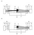
図4は、外径1.59mmおよび内径0.50mmのパイプPを用いた場合の出射光を示す図であり、図4(a)はパイプP内に液体が無い場合、図4(b)は液体がある場合を示す。なお、図4〜図6では液体として水を想定し、液体がない場合はパイプP内を空気が満たしているものとする。
不図示の位置決め部32により、パイプPの中心軸Xがスリット31の開口縁部33と同じ高さ位置に位置決めされている。図4(a)において、パイプP内に水が無い場合、投光素子12から投光された出射光はレンズ13およびスリット14を通過すると共にハウジング壁面11を透過して検出領域2に出射され(図4(a)に最も薄いグレーで示す)、パイプPの外周面で所定の屈折率で屈折し(図4(a)にやや濃いグレーで示す)、さらに内周面で所定の屈折率で屈折して(図4(a)に最も濃いグレーで示す)、一部の出射光がスリット31を通過する。そして、スリット31を通過した出射光が、ハウジング壁面21を透過すると共にスリット24を通過し、レンズ23で集光されて受光素子22へ到達する。受光素子22で受光した光は、不図示の信号処理部で電気信号に変換され、予め設定された閾値と比較され、液体の有無が判定される。具体的には、受光量を表す電気信号の値が閾値を超えた場合、投光部10から出射された光がパイプP内を透過して受光部20に到達したと判断して、パイプP内に液体が無いことを表す信号を出力する。FIG. 4 is a diagram showing emitted light when a pipe P having an outer diameter of 1.59 mm and an inner diameter of 0.50 mm is used. FIG. 4A shows a case where there is no liquid in the pipe P. FIG. Indicates the presence of liquid. 4 to 6, water is assumed as the liquid, and when there is no liquid, the pipe P is filled with air.
A center axis X of the pipe P is positioned at the same height as the opening
一方、図4(b)において、パイプP内に水がある場合、パイプP内に水がない場合に比べてパイプP内の屈折率が大きくなるので、投光部10から検出領域2に出射された出射光は(図4(b)に最も薄いグレーで示す)、主にパイプPの外周面で屈折し(図4(b)にやや濃いグレーで示す)、内周面と水との境界面ではほとんど屈折せずに進む(図4(b)に最も濃いグレーで示す)。そのため、出射光はアタッチメント30の板状部材に遮られ、スリット31を通過できない。よって、受光部20には外乱光が入射することはあっても、閾値を超える十分な量の受光量が入射することはない。この場合、不図示の信号処理部は、パイプP内に液体があることを表す信号を出力する。 On the other hand, in FIG. 4B, when there is water in the pipe P, the refractive index in the pipe P becomes larger than in the case where there is no water in the pipe P, so that the light is emitted from the
なお、ここではパイプPの材質としてPFA(フッ素樹脂、絶対屈折率1.34)、およびパイプP内を通過する液体を単に水(絶対屈折率1.33)とし、パイプP内に水がない場合、パイプP内は空気(絶対屈折率1.00)で満たされるものとして述べたが、これらの組み合わせに限られるものではなく、要はパイプP内に液体があるときと無いとき(パイプP内が何等かの気体で満たされるとき)の両者を比して当該液体と気体との屈折率が異なる場合であれば、同様に本発明を適用可能である。 Here, the material of the pipe P is PFA (fluororesin, absolute refractive index 1.34), and the liquid passing through the pipe P is simply water (absolute refractive index 1.33), and there is no water in the pipe P. In this case, the inside of the pipe P has been described as being filled with air (absolute refractive index 1.00). However, the present invention is not limited to the combination of these. If the refractive index of the liquid and the gas is different from each other when the inside is filled with some gas, the present invention can be similarly applied.
図5は、外径は1.59mmのまま、内径を0.75mmにしたパイプPを用いた場合の出射光を示す図であり、図5(a)はパイプP内に液体が無い場合、図5(b)は液体がある場合を示す。
また、図6は、外径は1.59mmのまま、内径を1.00mmにしたパイプPを用いた場合の出射光を示す図であり、図6(a)はパイプP内に液体が無い場合、図6(b)は液体がある場合を示す。
いずれの場合も、図4と同様に、パイプP内に液体が無いときは、出射光がパイプPの内周面で屈折してスリット31を通過し、受光部20に到達する。一方、パイプP内に液体があるときは、出射光はパイプPの内周面(と水との境界面)での屈折率が変わり、スリット31を通過できなくなるので受光部20に到達しない。このように、パイプPとスリット24との間にスリット31を設けることにより、1/16インチ以下の極細径のパイプPの内径が異なる場合であっても、液体の有無を検出可能である。FIG. 5 is a diagram showing the emitted light when the pipe P having an outer diameter of 1.59 mm and an inner diameter of 0.75 mm is used. FIG. 5A shows a case where there is no liquid in the pipe P. FIG. 5B shows a case where there is a liquid.
FIG. 6 is a diagram showing emitted light when the pipe P having an outer diameter of 1.59 mm and an inner diameter of 1.00 mm is used, and FIG. 6A shows no liquid in the pipe P. In this case, FIG. 6B shows a case where there is a liquid.
In any case, as in FIG. 4, when there is no liquid in the pipe P, the emitted light is refracted on the inner peripheral surface of the pipe P, passes through the
なお、図4〜図6に示すように、パイプP内に液体があっても無くても屈折した光の一部がスリット31の一端部にわずかに進入するため、スリット31を形成する板状部材にある程度の厚みを持たせることが望ましい。ただし、この板状部材を厚くしてスリット31をスリット24に連結させてしまうと、連結したスリットの内壁面で出射光が多重反射するなど、外乱光が発生する可能性があるため、スリット31を形成する板状部材とスリット24を形成する板状部材とは別体にし、かつ、離間させておく。 As shown in FIGS. 4 to 6, a part of the refracted light slightly enters one end of the
なお、図示例の液体センサにおいては、ハウジング壁面11からハウジング壁面21までの距離を13mmにしている。また、スリット14の開口幅を高さ方向2.0mm、左右方向1.0mm、スリット24の開口幅を高さ方向1.3mm、左右方向1.0mm、スリット31の開口幅を高さ方向0.5mm、左右方向2.0mmにしている。このうち、スリット31の高さ方向の開口幅(0.5mm)は、パイプPの外径(1.59mm)が小さくなるにつれて狭めることが好ましい。
また、図示例のように、スリット24の開口面積をスリット31の開口面積より大きくした場合、スリット31を通過した出射光がスリット24から受光素子22側へ入りやすくなるため、受光素子22における受光量が増えて検出感度が向上する。一方、スリット24の開口面積をスリット31の開口面積より小さくしてもよく、この場合、スリット24から受光素子22側へ外乱光が入りにくくなるため誤判定を防止できるようになる。In the illustrated liquid sensor, the distance from the
Further, as shown in the illustrated example, when the opening area of the
また、図示例の液体センサでは、投光部10からの出射光のうち、図面紙上において上方の出射光を利用してパイプPの液体の有無を検出しているが、これに限定されるものではなく、図示した液体センサのハウジング1以外の各部を上下方向に反転した構成にして、投光部10からの射出光のうち、下方の出射光を利用してパイプPの液体の有無を検出するようにしてもよい。この構成の場合、パイプPの中心軸Xがスリット31の下側の開口縁部に沿う位置に位置合わせされることになる。 Further, in the liquid sensor of the illustrated example, the presence or absence of liquid in the pipe P is detected using the outgoing light on the drawing paper out of the outgoing light from the
以上より、実施の形態1によれば、液体センサは、投光素子12の出射光をスリット14からパイプPの方向へ出射する投光部10と、投光部10からパイプPの方向へ出射された出射光を、スリット24を通して受光素子22で受光する受光部20と、パイプPとスリット24との間に配置され、投光部10からパイプPの方向へ出射された出射光を、パイプP内の液体が無いときにスリット24の方向へ選択的に通過させるスリット31とを備え、スリット31はパイプPの半径より小さく開口した形状であって、位置決め部32が、当該開口縁部33にパイプPの中心軸Xが沿うようにパイプPを位置決めするように構成した。このため、本来は大径パイプの液体の有無を検出する用に設計された液体センサであっても、スリット31を設けることにより、より細径のパイプPの液体の有無を検出することができる。さらに、内径が異なる極細径のパイプPであっても液体の有無を検出することができる。 As described above, according to the first embodiment, the liquid sensor emits light emitted from the
また、本実施の形態1ではアタッチメント30をハウジング1とは別体で構成している。そのため、ハウジング1に対してアタッチメント30を着脱可能にでき、例えば、パイプPの外径に応じてアタッチメント30を取り替えて、適切な開口幅のスリット31が形成されたアタッチメント30を用いて液体の有無を検出することもできる。さらに、アタッチメント30を取り外した状態で、検出領域2に大径のパイプPを固定すれば、大径のパイプPの液体の有無を検出できるようになる。従って、極細径から大径まで、様々な径のパイプPについて液体の有無を検出可能な、汎用的な液体センサを構成できる。 In the first embodiment, the
他方、スリット31および位置決め部32などをアタッチメント30として構成せず、ハウジング1と一体に構成してもよい。この構成の場合には、アタッチメント30をハウジング1に固定するための保持部40およびバンド41などが不要となり、液体センサを小型化できる。 On the other hand, the
さらに、保持部40は図示例に限定されるものではなく、アタッチメント30とパイプPとをハウジング1に固定できる構成であればよい。
図7に、変形例として、別形状の保持部を備える液体センサを示す。この変形例では、板状の保持部50および蓋体51を用いてパイプPをアタッチメント30の所定位置に固定する。具体的には、板状の保持部50をスリット14とパイプPとの間に形成して、スリット31を形成した板状部材にパイプPを押し当てた状態に保持させる。加えて、パイプPの高さ方向の位置を位置決め部32で決定して、蓋体51でパイプPを覆って高さ方向を固定させる。なお、保持部50は、透光性部材で構成するか、または十分な開口面積のスリットを形成するかして、投光部10からの出射光を遮らないようにする。Furthermore, the holding
FIG. 7 shows, as a modification, a liquid sensor including a holding unit having another shape. In this modification, the pipe P is fixed at a predetermined position of the
なお、本発明の実施形態を図面を参照して詳述してきたが、具体的な構成は、上述した実施の形態の構成に限られるものではなく、本発明の要旨を逸脱しない範囲の設計の変更などがあっても本発明に含まれることは言うまでもない。 Although the embodiment of the present invention has been described in detail with reference to the drawings, the specific configuration is not limited to the configuration of the above-described embodiment, and the design does not depart from the gist of the present invention. Needless to say, changes and the like are included in the present invention.
1 ハウジング
2 検出領域
10 投光部
11,21 ハウジング壁面
12 投光素子
13,23 レンズ
14 スリット(第1のスリット)
20 受光部
22 受光素子
24 スリット(第2のスリット)
30 アタッチメント
31 スリット(第3のスリット)
32 位置決め部
33 開口縁部
40,50 保持部
41 バンド
51 蓋体
P パイプDESCRIPTION OF SYMBOLS 1
20
30
32
Claims (4)
Translated fromJapanese前記投光部から前記管体の方向へ出射された前記出射光を、第2のスリットを通して受光素子で受光する受光部とを備え、
前記管体内に液体があるか無いかを、前記受光部における受光量に基づいて検出する液体センサにおいて、
前記管体と前記第2のスリットとの間に配置され、前記投光部から前記管体の方向へ出射された前記出射光を、前記管体内の液体が無いときに前記第2のスリットの方向へ選択的に通過させる第3のスリットを備え、
前記第3のスリットは、前記管体の半径より小さく開口した形状であって、当該開口縁部に前記管体の中心軸が位置合わせされることを特徴とする液体センサ。A light projecting unit that emits light emitted from the light projecting element through the first slit toward the translucent tube;
A light receiving portion that receives the emitted light emitted from the light projecting portion in the direction of the tubular body by a light receiving element through a second slit;
In the liquid sensor that detects whether there is liquid in the tube based on the amount of light received in the light receiving unit,
The emitted light, which is disposed between the tubular body and the second slit and is emitted from the light projecting unit in the direction of the tubular body, emits the second slit when there is no liquid in the tubular body. A third slit selectively passing in the direction,
The liquidslit is characterized in that the third slit has a shape opened smaller than the radius of the tubular body, and the central axis of the tubular body is aligned with the opening edge .
前記ハウジングの窪んだ部分に取り付け可能なアタッチメントとを備え、
前記アタッチメントに第3のスリットを設けたことを特徴とする請求項1から請求項3のうちのいずれか1項記載の液体センサ。A light projecting element and a light receiving element are accommodated in a pair of convex structures sandwiched between the recessed portions, and a first slit and a second slit are formed on the wall surfaces of the pair of convex structures facing each other across the recessed portions. A provided housing;
An attachment that can be attached to the recessed portion of the housing,
Liquid sensor according to any one of claims 1 to3, characterized in that a third slits in said attachment.
Priority Applications (4)
| Application Number | Priority Date | Filing Date | Title |
|---|---|---|---|
| JP2011131348AJP5773770B2 (en) | 2011-06-13 | 2011-06-13 | Liquid sensor |
| US13/493,492US20120314217A1 (en) | 2011-06-13 | 2012-06-11 | Fluid sensor |
| CN201210191034.4ACN102853879B (en) | 2011-06-13 | 2012-06-11 | Fluid sensor |
| EP12171769AEP2535699A1 (en) | 2011-06-13 | 2012-06-13 | Fluid sensor |
Applications Claiming Priority (1)
| Application Number | Priority Date | Filing Date | Title |
|---|---|---|---|
| JP2011131348AJP5773770B2 (en) | 2011-06-13 | 2011-06-13 | Liquid sensor |
Publications (2)
| Publication Number | Publication Date |
|---|---|
| JP2013002842A JP2013002842A (en) | 2013-01-07 |
| JP5773770B2true JP5773770B2 (en) | 2015-09-02 |
Family
ID=47292935
Family Applications (1)
| Application Number | Title | Priority Date | Filing Date |
|---|---|---|---|
| JP2011131348AActiveJP5773770B2 (en) | 2011-06-13 | 2011-06-13 | Liquid sensor |
Country Status (3)
| Country | Link |
|---|---|
| US (1) | US20120314217A1 (en) |
| JP (1) | JP5773770B2 (en) |
| CN (1) | CN102853879B (en) |
Families Citing this family (4)
| Publication number | Priority date | Publication date | Assignee | Title |
|---|---|---|---|---|
| CN107003174A (en)* | 2016-04-15 | 2017-08-01 | 五洋建设株式会社 | Bulk material detection means and mesa-shaped thing build method |
| DE102016114607B4 (en) | 2016-08-05 | 2025-03-20 | Infineon Technologies Ag | Liquid delivery system, device and method |
| CN109884063B (en)* | 2019-04-24 | 2021-08-20 | 杭州翔毅科技有限公司 | Acquisition structure for liquid sensor |
| CN111157076B (en)* | 2020-02-20 | 2020-10-23 | 郑州富铭环保科技股份有限公司 | Device for monitoring water level |
Family Cites Families (17)
| Publication number | Priority date | Publication date | Assignee | Title |
|---|---|---|---|---|
| US2775159A (en)* | 1952-02-20 | 1956-12-25 | Joseph C Frommer | Method and apparatus for the counting of particles per unit volume in a fluid |
| US3999856A (en)* | 1976-01-02 | 1976-12-28 | Monsanto Research Corporation | Diffractometric refractometer |
| US4243883A (en)* | 1979-01-19 | 1981-01-06 | Midwest Cardiovascular Institute Foundation | Blood hematocrit monitoring system |
| US4291230A (en)* | 1979-03-07 | 1981-09-22 | Baxter Travenol Laboratories, Inc. | Fluorometric analyzer including shutter means for simultaneously shielding sample and photodetector during sample change |
| US5354440A (en)* | 1988-11-29 | 1994-10-11 | Isco, Inc. | Capillary electrophoresis technique |
| US5153436A (en)* | 1990-05-23 | 1992-10-06 | Ntc Technology, Inc. | Temperature controlled detectors for infrared-type gas analyzers |
| US5672887A (en)* | 1995-11-29 | 1997-09-30 | Shaw; Benjamin G. | Optical detector for air in fluid line the same |
| JP3741509B2 (en)* | 1997-03-12 | 2006-02-01 | シスメックス株式会社 | Tube liquid sensor |
| SE9804142D0 (en)* | 1998-11-30 | 1998-11-30 | Gambro Ab | Method and device for providing a signal |
| JP2001336966A (en)* | 2000-05-29 | 2001-12-07 | Sunx Ltd | Liquid detecting apparatus |
| JP3719130B2 (en)* | 2000-11-10 | 2005-11-24 | 株式会社山武 | Liquid level monitoring device |
| US6947131B2 (en)* | 2002-05-07 | 2005-09-20 | Chf Solutions, Inc. | Blood leak detector for extracorporeal treatment system |
| JP2006003233A (en)* | 2004-06-17 | 2006-01-05 | Otsuka Denshi Co Ltd | Optical cell measuring device |
| JP2007316041A (en)* | 2006-05-23 | 2007-12-06 | Sakata Denki | Liquid level detection device |
| US7535571B2 (en)* | 2006-07-26 | 2009-05-19 | Mitsubishi Electric Research Laboratories, Inc. | Optical fluid level encoder |
| JP2009133747A (en)* | 2007-11-30 | 2009-06-18 | Horiba Ltd | Channel sensor |
| DE102010038329B4 (en)* | 2010-07-23 | 2014-02-06 | Bruker Optik Gmbh | IR spectrometer with non-contact temperature measurement |
- 2011
- 2011-06-13JPJP2011131348Apatent/JP5773770B2/enactiveActive
- 2012
- 2012-06-11USUS13/493,492patent/US20120314217A1/ennot_activeAbandoned
- 2012-06-11CNCN201210191034.4Apatent/CN102853879B/enactiveActive
Also Published As
| Publication number | Publication date |
|---|---|
| JP2013002842A (en) | 2013-01-07 |
| CN102853879A (en) | 2013-01-02 |
| CN102853879B (en) | 2014-08-13 |
| US20120314217A1 (en) | 2012-12-13 |
Similar Documents
| Publication | Publication Date | Title |
|---|---|---|
| JP6303388B2 (en) | Limited-area reflective optical sensor and electronic device | |
| JP5773770B2 (en) | Liquid sensor | |
| JP5870270B2 (en) | Detector | |
| EP2325597B1 (en) | Non-contact optical probe and measuring machine | |
| TW201308134A (en) | Optical pointing apparatus | |
| JP6614909B2 (en) | Photoelectric sensor | |
| EP2535699A1 (en) | Fluid sensor | |
| JP5828073B2 (en) | Infrared sensor | |
| JP5128232B2 (en) | Reflective photoelectric sensor | |
| CN207081463U (en) | liquid sensor | |
| KR101725797B1 (en) | Light projection head and optical sensor | |
| JP6611345B2 (en) | Liquid sensor and tube holding member of liquid sensor | |
| JP2006300793A (en) | Optical liquid level sensor | |
| JP5199083B2 (en) | Flow path sensor and tube fixture used therefor | |
| JP3548092B2 (en) | Liquid detector | |
| JP4087291B2 (en) | Tube liquid sensor | |
| JP2012093232A (en) | Photosensor and level sensor | |
| JP2009133747A (en) | Channel sensor | |
| JP6510270B2 (en) | Liquid level detection device | |
| KR200485081Y1 (en) | A smart pen with the transparent cover | |
| JP3863448B2 (en) | Liquid level detector | |
| JP2001337005A (en) | Liquid leak sensor | |
| JP4400643B2 (en) | Pulse wave sensor | |
| JP4566659B2 (en) | Photodetector | |
| JP6414351B2 (en) | Limited-area reflective optical sensor and electronic device |
Legal Events
| Date | Code | Title | Description |
|---|---|---|---|
| A621 | Written request for application examination | Free format text:JAPANESE INTERMEDIATE CODE: A621 Effective date:20140324 | |
| A977 | Report on retrieval | Free format text:JAPANESE INTERMEDIATE CODE: A971007 Effective date:20141210 | |
| A131 | Notification of reasons for refusal | Free format text:JAPANESE INTERMEDIATE CODE: A131 Effective date:20141224 | |
| A521 | Request for written amendment filed | Free format text:JAPANESE INTERMEDIATE CODE: A523 Effective date:20150210 | |
| TRDD | Decision of grant or rejection written | ||
| A01 | Written decision to grant a patent or to grant a registration (utility model) | Free format text:JAPANESE INTERMEDIATE CODE: A01 Effective date:20150602 | |
| A61 | First payment of annual fees (during grant procedure) | Free format text:JAPANESE INTERMEDIATE CODE: A61 Effective date:20150630 | |
| R150 | Certificate of patent or registration of utility model | Ref document number:5773770 Country of ref document:JP Free format text:JAPANESE INTERMEDIATE CODE: R150 | |
| R250 | Receipt of annual fees | Free format text:JAPANESE INTERMEDIATE CODE: R250 | |
| R250 | Receipt of annual fees | Free format text:JAPANESE INTERMEDIATE CODE: R250 |