JP5773615B2 - Scroll compressor - Google Patents
Scroll compressorDownload PDFInfo
- Publication number
- JP5773615B2 JP5773615B2JP2010242890AJP2010242890AJP5773615B2JP 5773615 B2JP5773615 B2JP 5773615B2JP 2010242890 AJP2010242890 AJP 2010242890AJP 2010242890 AJP2010242890 AJP 2010242890AJP 5773615 B2JP5773615 B2JP 5773615B2
- Authority
- JP
- Japan
- Prior art keywords
- scroll
- wrap wall
- fixed
- orbiting scroll
- wall
- Prior art date
- Legal status (The legal status is an assumption and is not a legal conclusion. Google has not performed a legal analysis and makes no representation as to the accuracy of the status listed.)
- Expired - Fee Related
Links
- 230000006835compressionEffects0.000claimsdescription85
- 238000007906compressionMethods0.000claimsdescription85
- 230000002093peripheral effectEffects0.000claimsdescription85
- 239000012530fluidSubstances0.000claimsdescription31
- 239000003507refrigerantSubstances0.000claimsdescription11
- 238000007599dischargingMethods0.000claimsdescription4
- 238000007789sealingMethods0.000claimsdescription4
- 239000000919ceramicSubstances0.000description2
- 230000007423decreaseEffects0.000description2
- 230000002452interceptive effectEffects0.000description2
- 239000010687lubricating oilSubstances0.000description2
- 235000014676Phragmites communisNutrition0.000description1
- 230000002411adverseEffects0.000description1
- 230000000903blocking effectEffects0.000description1
- 230000001276controlling effectEffects0.000description1
- 230000003247decreasing effectEffects0.000description1
- 238000010586diagramMethods0.000description1
- 230000000694effectsEffects0.000description1
- 238000004519manufacturing processMethods0.000description1
- 239000000463materialSubstances0.000description1
- 238000000034methodMethods0.000description1
- 239000003921oilSubstances0.000description1
- 230000001105regulatory effectEffects0.000description1
- XLYOFNOQVPJJNP-UHFFFAOYSA-NwaterSubstancesOXLYOFNOQVPJJNP-UHFFFAOYSA-N0.000description1
Images


Landscapes
- Rotary Pumps (AREA)
- Applications Or Details Of Rotary Compressors (AREA)
Description
Translated fromJapanese本発明は、空気調和機等に用いられるスクロール圧縮機に関する。 The present invention relates to a scroll compressor used for an air conditioner or the like.
空気調和機等に用いられるスクロール圧縮機は、固定スクロールと旋回スクロールとを備える。固定スクロール、旋回スクロールは、それぞれ円板状の端板の一面側に、渦巻状のラップ壁が一体に形成されたものである。このような固定スクロールと旋回スクロールを、ラップ壁を噛み合わせた状態で対向させ、固定スクロールに対して旋回スクロールを公転旋回運動させる。そして、双方のラップ壁の間に形成される圧縮空間を外周側から内周側に移動させつつその容積を減少させることで、圧縮空間内の流体の圧縮を行う。 A scroll compressor used for an air conditioner or the like includes a fixed scroll and a turning scroll. Each of the fixed scroll and the orbiting scroll is formed by integrally forming a spiral wrap wall on one surface side of a disk-shaped end plate. The fixed scroll and the orbiting scroll are made to face each other with the lap wall meshed, and the orbiting scroll is caused to make a revolving orbit with respect to the fixed scroll. And the fluid in compression space is compressed by reducing the volume, moving the compression space formed between both lap walls from the outer peripheral side to the inner peripheral side.
このようなスクロール圧縮機においては、圧縮空間内の流体の圧縮の過程に、流体の一部を逃がすことで、特に低能力時(低回転時)における圧力損失を低減する、容量制御を行うものがある(例えば、特許文献1参照。)。容量制御型のスクロール圧縮機においては、固定スクロールにバイパス穴を設け、低能力時には、このバイパス穴を開く制御を行うことで、圧縮空間内の流体の一部を逃がしている。 In such a scroll compressor, a part of the fluid is released during the process of compressing the fluid in the compression space, and the capacity control is performed to reduce the pressure loss especially at the time of low capacity (low rotation). (For example, refer to Patent Document 1). In the capacity-controlled scroll compressor, a bypass hole is provided in the fixed scroll, and when the capacity is low, by controlling the opening of the bypass hole, a part of the fluid in the compression space is released.
しかしながら、従来の容量制御型のスクロール圧縮においては、以下に示すような問題が存在する。
まず、固定スクロールに対する旋回スクロールの旋回により、固定スクロールに形成されたバイパス穴は、常にその一部が旋回スクロールのラップ壁によって塞がれることになる。したがって、バイパス穴の開口面積に対し、実際に流体の排出に寄与する有効面積が小さく、圧力損失低減の効率向上が妨げられるという問題がある。However, the conventional capacity-controlled scroll compression has the following problems.
First, by turning the orbiting scroll with respect to the fixed scroll, a part of the bypass hole formed in the fixed scroll is always blocked by the wrap wall of the orbiting scroll. Therefore, there is a problem that the effective area that actually contributes to the fluid discharge is smaller than the opening area of the bypass hole, which hinders improvement in efficiency of pressure loss reduction.
また、固定スクロール、旋回スクロールのラップ壁の先端部には、ラップ壁に対向する旋回スクロールまたは固定スクロールの端板との間のシール性を確保するとともに、摩擦を低減するために、セラミック等からなるチップシールが設けられている。このチップシールは、前述の固定スクロールに対する旋回スクロールの旋回時において、バイパス穴の周縁部に近接しながら動く。固定スクロール、旋回スクロールの製造時における加工誤差、あるいはチップシールの旋回スクロールに対する組み付け誤差、温度上昇に伴う各部の膨張等により、チップシールとバイパス穴のクリアランスが想定以上に小さくなり、これらが互いに干渉してしまう可能性もある。チップシールがバイパス穴の周縁部に干渉すると、チップシールが破損したり、傷ついたりして、スクロール圧縮機の耐久性、信頼性に悪影響を与えることもある。 In addition, the tip of the wrap wall of the fixed scroll and the orbiting scroll is made of ceramic or the like in order to secure a sealing property between the end plate of the orbiting scroll or the fixed scroll facing the wrap wall and reduce friction. A tip seal is provided. The tip seal moves while approaching the peripheral edge portion of the bypass hole when the orbiting scroll is turned relative to the fixed scroll. The clearance between the tip seal and the bypass hole becomes smaller than expected due to processing errors during manufacturing of the fixed scroll and the orbiting scroll, or the assembly error of the tip seal with respect to the orbiting scroll and the expansion of each part due to the temperature rise. There is also a possibility of doing. If the chip seal interferes with the peripheral edge of the bypass hole, the chip seal may be damaged or damaged, which may adversely affect the durability and reliability of the scroll compressor.
また、固定スクロールのラップ壁と旋回スクロールのラップ壁とによって囲まれた圧縮空間内の流体は、固定スクロールに対する旋回スクロールの旋回によって圧縮されるが、圧縮空間が固定スクロールのラップ壁と旋回スクロールのラップ壁とによって囲まれて圧縮空間が締め切られるタイミングと、圧縮空間の一部がバイパス穴に臨む位置に到達して、バイパス穴から圧縮空間内の流体の一部が流れ出るタイミングとが一致するとは限らない。圧縮空間が閉塞され、さらに固定スクロールに対する旋回スクロールの旋回により、圧縮空間内の流体が圧縮し始めても、バイパス穴から圧縮空間内の流体が流れ出ないと、圧縮空間内の流体の圧力が高まり、旋回スクロールの旋回に高いエネルギーを要し、すなわち圧力損失が大きくなる。
したがって、特に、圧縮し始めるタイミングにおいて、圧縮空間内の流体をバイパス穴から速やかに排出して容量制御を円滑に行う点において、改善の余地が存在するということになる。
本発明は、このような技術的課題に基づいてなされたもので、容量制御時における圧力損失を低減し、より効率よく容量制御を行うことができ、また高い耐久性、信頼性を得ることのできるスクロール圧縮機を提供することを目的とする。In addition, the fluid in the compression space surrounded by the fixed scroll wrap wall and the orbiting scroll wrap wall is compressed by the orbiting scroll turning with respect to the fixed scroll. The timing when the compression space is closed by being surrounded by the wrap wall coincides with the timing at which a part of the compression space reaches the position where it faces the bypass hole and a part of the fluid in the compression space flows out of the bypass hole. Not exclusively. Even if the fluid in the compression space begins to compress due to the turning of the orbiting scroll with respect to the fixed scroll, and the fluid in the compression space does not flow out of the bypass hole, the pressure of the fluid in the compression space increases. High energy is required for turning the orbiting scroll, that is, pressure loss increases.
Therefore, there is room for improvement, particularly in the point that the fluid in the compression space is quickly discharged from the bypass hole to smoothly control the capacity at the timing when compression starts.
The present invention has been made based on such a technical problem, and can reduce pressure loss during capacity control, perform capacity control more efficiently, and obtain high durability and reliability. An object of the present invention is to provide a scroll compressor that can be used.
かかる目的のもと、本発明のスクロール圧縮機は、外殻を形成するハウジング内に回転自在に支持された主軸と、主軸の中心に対してオフセットした位置に回転自在に連結され、円板状の旋回側端板に渦巻き状の旋回スクロール側ラップ壁が形成された旋回スクロールと、ハウジングに固定され、円板状の固定側端板に旋回スクロール側ラップ壁に対向する渦巻き状の固定スクロール側ラップ壁が形成されて、旋回スクロールと対向することで、旋回側端板、旋回スクロール側ラップ壁、固定側端板、固定スクロール側ラップ壁に囲まれて冷媒を圧縮する圧縮空間を形成する固定スクロールと、を備える。
さらに、固定側端板に、固定スクロール側ラップ壁によって区画されて形成される渦巻き状の溝底面が、第一の溝底面と、第一の溝底面よりも旋回スクロール側に位置する第二の溝底面とを備えている。
第一の溝底面は固定側端板において外周側に設けられるとともに、第二の溝底面は第一の溝底面に対して固定側端板の内周側に設けられることで、旋回スクロールと固定スクロールとの間に形成される圧縮空間は、外周側から内周側に向けてその断面積が漸次縮小する。
第一の溝底面と第二の溝底面との段部に対して第一の溝底面側に、圧縮空間内の流体を外部に排出するポート孔が形成され、ポート孔の周縁は、段部の位置にあることを特徴とする。
固定側端板の第一の溝底面と第二の溝底面との段部には、この段部に対応した段差を有する旋回スクロール側ラップ壁が対向する。固定側端板の第一の溝底面と第二の溝底面との段部に対して第一の溝底面側に、圧縮空間内の流体を外部に排出するポート孔を、その周縁が段部の位置にあるように形成すると、ポート孔には、旋回スクロール側ラップ壁の段差の部分が対向する。これにより、旋回スクロール側ラップ壁の段差がポート孔の周囲に沿って旋回することになり、少なくともポート孔の半周分においては、ポート孔には段差の一方の側の旋回スクロール側ラップ壁の背の低い部分が対向し、ポート孔を閉塞するのを回避できる。For this purpose, the scroll compressor according to the present invention is connected to a main shaft rotatably supported in a housing forming an outer shell, and is rotatably connected to a position offset with respect to the center of the main shaft. The orbiting scroll having a spiral orbiting scroll side wrap wall formed on the orbiting side end plate, and the spiral fixed scroll side fixed to the housing and opposed to the orbiting scroll side wrap wall by the disk-like stationary side end plate A wrap wall is formed, facing the orbiting scroll, and fixed to form a compression space that compresses the refrigerant surrounded by the orbiting side end plate, the orbiting scroll side wrap wall, the fixed side end plate, and the fixed scroll side wrap wall Scroll.
Further, a spiral groove bottom surface defined by the fixed scroll side wrap wall on the fixed side end plate has a first groove bottom surface and a second scroll surface positioned closer to the orbiting scroll than the first groove bottom surface. A groove bottom surface.
The first groove bottom surface is provided on the outer peripheral side of the fixed side end plate, and the second groove bottom surface is provided on the inner peripheral side of the fixed side end plate with respect to the first groove bottom surface. The compression space formed between the scroll and the cross-sectional area gradually decreases from the outer peripheral side toward the inner peripheral side.
Thefirst groove bottom side of the stepped portion of the first groove bottom surface and the second groove bottom, port hole for discharging the fluid in the compression space to the outside are formed, the periphery of the port hole,stepped portions It is in the position of .
The orbiting scroll side wrap wall having a step corresponding to the stepportion is opposed to thestep portion between the first groove bottom surface and the second groove bottom surface of the fixed side end plate. A port hole for discharging the fluid in the compression space to the outsideon the first groove bottom surface side with respect to thestep portion between the first groove bottom surface and the second groove bottom surface of the fixed side end plate, the periphery of which is a step portion If it formsso that it may existin this position, the level | step-difference part of a turning scroll side lap wall opposes a port hole. As a result, the step of the orbiting scroll side wrap wall turns along the periphery of the port hole, and at least for the half circumference of the port hole, the port hole has a back of the orbiting scroll side wrap wall on one side of the step. It is possible to avoid blocking the port hole by facing the low portion of the port.
ポート孔は、圧縮空間を締め切った状態から圧縮空間を早期にポート孔に連通させることができるのであれば、その位置を何ら限定するものではない。旋回スクロールの旋回動作により、旋回スクロール側ラップ壁の外周側の終端部が、固定スクロール側ラップ壁に突き当たることで圧縮空間を締め切った状態で、ポート孔は、旋回スクロール側ラップ壁の外周側の終端部位置と、終端部の固定スクロール側ラップ壁への突き当たり位置に対して固定スクロール側ラップ壁を挟んで対向する位置との間に形成するのが好ましい。
この中でも、ポート孔は、終端部の固定スクロール側ラップ壁への突き当たり位置に対し、固定スクロール側ラップ壁を挟んで対向する位置に形成するのが特に好ましい。旋回スクロール側ラップ壁において、外周側の終端部から360°内周側の位置が固定スクロール側ラップ壁に突き当たることによって、固定スクロール側ラップ壁と、旋回スクロール側ラップ壁との間に圧縮空間が形成される。圧縮空間は、内周側の始端が、旋回スクロール側ラップ壁の外周側の終端部から360°内周側の位置と固定スクロール側ラップ壁とが突き当たった位置となり、この位置には、ポート孔が形成されている。これにより、旋回スクロール側ラップ壁の外周側の終端部が固定スクロール側ラップ壁に突き当たることで圧縮空間を締め切った状態から、さらに旋回スクロールを旋回させるときには、圧縮空間の内周側の始端がポート孔に臨む状態にあり、ポート孔から圧縮空間内の流体を排出することができる。The position of the port hole is not limited as long as the compression space can be communicated with the port hole at an early stage from the state where the compression space is closed. With the turning operation of the orbiting scroll, the end of the outer peripheral side of the orbiting scroll side wrap wall hits the fixed scroll side wrap wall to close the compression space. It is preferable to form between the end portion position and a position facing the end portion of the end portion against the fixed scroll side wrap wall with the fixed scroll side wrap wall interposed therebetween.
Among these, it is particularly preferable that the port hole is formed at a position facing the abutting position of the end portion of the fixed scroll side wrap wall with the fixed scroll side wrap wall interposed therebetween. In the orbiting scroll side wrap wall, the 360 ° inner circumference side position of the outer peripheral side end portion abuts against the fixed scroll side wrap wall, so that a compression space is formed between the fixed scroll side wrap wall and the orbiting scroll side wrap wall. It is formed. In the compression space, the inner peripheral side start end is a position where the 360 ° inner peripheral side position and the fixed scroll side wrap wall abut against the outer peripheral end part of the orbiting scroll side wrap wall. Is formed. As a result, when the end of the outer periphery of the orbiting scroll side wrap wall abuts against the fixed scroll side lap wall and the orbiting scroll is further swung from the state where the compression space is closed, the start end on the inner periphery side of the compression space is the port. It is in a state facing the hole, and the fluid in the compression space can be discharged from the port hole.
旋回スクロールの旋回動作により、旋回スクロール側ラップ壁の外周側の終端部が、固定スクロール側ラップ壁に最も接近した状態において、終端部と固定側ラップ壁との間に隙間を形成することもできる。旋回スクロール側ラップ壁の外周側の終端部が、固定スクロール側ラップ壁に突き当たることで圧縮空間を締め切った状態から、さらに旋回スクロールを旋回させると、終端部と固定側ラップ壁との間に形成された隙間から圧縮空間内の流体を排出することができる。 By the turning operation of the orbiting scroll, a gap can be formed between the end portion and the fixed side wrap wall in a state where the outer peripheral side end portion of the orbiting scroll side wrap wall is closest to the fixed scroll side wrap wall. . Formed between the terminal portion and the fixed side wrap wall when the orbiting scroll is further swung from the state where the outer end of the orbiting scroll side wrap wall hits the fixed scroll side wrap wall and the compression space is closed. The fluid in the compression space can be discharged from the formed gap.
また、旋回スクロール側ラップ壁は、固定側端板に対向する先端部に、当該旋回スクロール側ラップ壁と固定側端板との間でのシール性を確保するためのチップシールが設けられるとともに、旋回スクロールの旋回動作中、ポート孔と対向する範囲には、チップシールが欠落したチップシール欠落部を形成することもできる。これにより、ポート孔と旋回スクロール側ラップ壁とが干渉するのを避けることができる。 In addition, the orbiting scroll side wrap wall is provided with a tip seal at the tip portion facing the fixed side end plate to ensure a sealing property between the orbiting scroll side wrap wall and the fixed side end plate. During the turning operation of the orbiting scroll, a chip seal missing portion in which the chip seal is missing may be formed in a range facing the port hole. Thereby, it can avoid that a port hole and a turning scroll side lap wall interfere.
本発明によれば、旋回スクロール側ラップ壁によってポート孔を閉塞する時間を抑えることができる。また、圧縮空間を締め切った状態から圧縮空間を早期にポート孔に連通させることで、圧縮空間内の流体を速やかに排出できる。これにより、容量制御時における圧力損失を低減し、より効率よく容量制御を行うことができる。
また、ポート孔と旋回スクロール側ラップ壁との干渉を避けることができ、高い耐久性、信頼性を得ることが可能となる。According to the present invention, the time for closing the port hole by the orbiting scroll side wrap wall can be suppressed. Moreover, the fluid in compression space can be discharged | emitted rapidly by making compression space communicate with a port hole at an early stage from the state which closed compression space. Thereby, the pressure loss at the time of capacity | capacitance control can be reduced and capacity | capacitance control can be performed more efficiently.
In addition, interference between the port hole and the orbiting scroll side wrap wall can be avoided, and high durability and reliability can be obtained.
以下、添付図面に示す実施の形態に基づいてこの発明を詳細に説明する。
図1は、本実施の形態におけるスクロール圧縮機の構成を説明するための図である。
[第一の実施の形態]
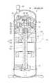
図1は、本実施の形態における圧縮機の構成を説明するための断面図である。
この図1に示すように、圧縮機10Aは、縦型のスクロール型で、ハウジング11内に、主軸12と、主軸12とともに回転する旋回スクロール20と、ハウジング11に固定された固定スクロール30と、を備える。
このような圧縮機10Aにおいては、ハウジング11の一端側に形成された冷媒導入ポートP1からハウジング11内に冷媒が導入され、旋回スクロール20と固定スクロール30との間に形成された圧縮空間において冷媒が圧縮される。そして、圧縮された冷媒は、ハウジング11の他端側に形成された冷媒吐出ポートP2から吐出される。Hereinafter, the present invention will be described in detail based on embodiments shown in the accompanying drawings.
FIG. 1 is a diagram for explaining a configuration of a scroll compressor according to the present embodiment.
[First embodiment]
FIG. 1 is a cross-sectional view for explaining the configuration of the compressor in the present embodiment.
As shown in FIG. 1, the compressor 10 </ b> A is a vertical scroll type, and includes a
In such a compressor 10 </ b> A, the refrigerant is introduced into the housing 11 from the refrigerant introduction port P <b> 1 formed on one end side of the housing 11, and the refrigerant is compressed in the compression space formed between the orbiting
旋回スクロール20は、円板状の端板(旋回側端板)21に、渦巻き状で所定の高さを有したラップ壁(旋回スクロール側ラップ壁)22が一体に形成されている。
一方、固定スクロール30は、旋回スクロール20に対向する端板(固定側端板)31には、旋回スクロール20のラップ壁22に対向して噛み合う渦巻き状のラップ壁(固定スクロール側ラップ壁)32が形成されている。In the
On the other hand, the fixed
このようにして、旋回スクロール20と固定スクロール30は、ラップ壁22とラップ壁32を互いに組み合わせている。これにより、旋回スクロール20と固定スクロール30との間に、圧縮空間50を形成している。
これにより、旋回スクロール20、固定スクロール30の外周側から圧縮空間50に導入された冷媒は、固定スクロール30に対する旋回スクロール20の公転により、外周側から内周側に順次送られて圧縮される。圧縮空間50で圧縮された冷媒は、固定スクロール30に形成された吐出孔37、吐出孔37に設けられたリード弁38、固定スクロール30を覆うように設けられた上部カバー39に設けられたリード弁40を介し、ハウジング11の他端側に形成された冷媒吐出ポートP2から吐出される。In this way, the orbiting
Thereby, the refrigerant introduced into the
主軸12は、その両端部が、ハウジング11に軸受13、14を介して回転自在に支持されている。主軸12は、ハウジング11内面に固定された固定子15と、主軸12の外周面に固定され、固定子15と対向する回転子16とからなるモータ17によって回転駆動される。なお、主軸12は、一端をハウジング11を貫通して外部に突出させ、エンジンや外部に設けられたモータ等の図示しない駆動源が主軸12の一端に連結されることで回転駆動される構成とすることもできる。 Both ends of the
主軸12の他端部には、主軸12の中心軸から予め定められた寸法だけ偏心した位置に、ボス18が突出形成されている。旋回スクロール20の主軸12側には、ボス18を収容する凹部23が形成されている。ボス18が、凹部23にドライブブッシュ(軸受)24を介して挿入されることで、このボス18に、旋回スクロール20が回転自在に保持されている。これにより、旋回スクロール20は、主軸12の中心に対し、予め定められた寸法だけ偏心して設けられ、主軸12がその軸線周りに回転すると、旋回スクロール20は、主軸12の中心に対して偏心した寸法を半径とした回転(公転)を行う。なお、旋回スクロール20が公転しつつも自転はしないよう、旋回スクロール20と主軸12との間には、オルダムリング(図示無し)が介在している。
また、主軸12には、ハウジング11の底部のオイル溜りから吸い上げた潤滑油を主軸12の上端部から主軸12と凹部23との間のドライブブッシュ24に供給するための潤滑油流路12aが形成されている。On the other end portion of the
Further, the
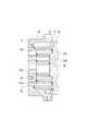
さて、ここで、旋回スクロール20と固定スクロール30との間に形成される圧縮空間50の断面積が、外周側から内周側に向けて漸次縮小する度合いを高めるため、旋回スクロール20の端板21の両面側において、旋回スクロール20と固定スクロール30のラップ高さが外周側から内周側に向けて漸次縮小するようにする。
これには、図2に示すように、旋回スクロールの端板21は、外周部21Aの厚さに対し内周部21Bの厚さが大きくなるように形成されている。一方、固定スクロール30の端板31は、外周部31Aの厚さに対し内周部31Bの厚さが大きくなるように形成されている。これに伴い、旋回スクロール20のラップ壁22、固定スクロール30のラップ壁32の高さは、外周側から内周側に漸次縮小されるように形成されている。このようにして、旋回スクロール20と固定スクロール30のラップ高さは、固定スクロール30の外周側から内周側に向けて段階的に(階段状に)低くなっている。Now, in order to increase the degree that the cross-sectional area of the
To this end, as shown in FIG. 2, the
ここで、旋回スクロール20のラップ壁22、固定スクロール30のラップ壁32において、固定スクロール30の端板31、旋回スクロール20の端板21と対向する先端部には、シール性を高めるため、セラミック系材料等からなるチップシール28、38が設けられている。 Here, in the
さて、図3、図4に示すように、このような圧縮機10Aにおいて、固定スクロール30の端板31には、ポート孔60が形成されている。このポート孔60は、端板31とラップ壁32とによって区画されて形成される螺旋状の溝100の溝底面100aに、溝100の幅と同じ直径を有して形成されている。ポート孔60は、溝100の溝底面100aにおいて、端板31の厚さが変わる外周部(第一の溝底面)31Aと内周部(第二の溝底面)31Bとの段部61Aの部分に、より詳しくは、段部61Aに対して端板31の厚さが小さな外周部31A側に形成されている。 As shown in FIGS. 3 and 4, in such a compressor 10 </ b> A, a
旋回スクロール20は、ラップ壁22の高さが、この段部61Aに対応した部分において、高壁部22Hから低壁部22Lへと高さが切り替わる段差部62とされている。段差部62において、ラップ壁22の先端部は、高壁部22H側の端部のポート孔対向部63においてポート孔60に対向する。 The orbiting
図5に示すように、旋回スクロール20が固定スクロール30に対して旋回すると、ラップ壁22の段差部62が、ポート孔60の外周縁部に沿った軌跡を描いて旋回する。
このとき、図5(b)、(c)に示すように、段差部62側が、ポート孔60において段部61Aから離間した側の半周部分R1に対向している状態においては、ポート孔60には、ラップ壁22の低壁部22Lが対向している。このため、ポート孔60の一部がラップ壁22によって塞がれることもなく、ポート孔60から圧縮空間50内の流体を効率よく排出できる。
一方、旋回スクロール20のラップ壁22において、図5(a)、(d)に示すように、ラップ壁22の段差部62が、ポート孔60において段部61Aに近い側の半周部分R2に対向している状態においては、ポート孔60には、ラップ壁22の高壁部22Hが対向している。このため、ポート孔60の一部がラップ壁22によって塞がれてしまう。そこで、本実施形態においては、ラップ壁22の高壁部22Hにおいて、旋回スクロール20の旋回によってポート孔60と対向する範囲(少なくとも段差部62からポート孔60の直径に対応するポート孔対向部63の範囲)は、チップシール28が欠落したチップシール欠落部64とされている。チップシール欠落部64においては、ラップ壁22の高さが、チップシール28が設けられている部分に比較すると、チップシール28の厚さ分だけ、低く形成されている。これにより、ラップ壁22の段差部62が、ポート孔60において段部61Aに近い側の半周部分R2に対向している状態において、ラップ壁22の高壁部22Hによってポート孔60の一部が塞がれている状態においても、ポート孔60には、チップシール欠落部64が対向している。したがって、ポート孔60とラップ壁22との間には、少なくともチップシール28の厚さ分の隙間が形成されており、ポート孔60からの流体の排出が妨げられるのを抑えることができる。As shown in FIG. 5, when the orbiting
At this time, as shown in FIGS. 5B and 5C, in the state where the stepped
On the other hand, in the
上述したような構成によれば、ポート孔60が、端板31の厚さが変わる段部61Aに形成され、ラップ壁22は、段部61Aに対応した段差部62において、高壁部22Hのポート孔対向部63がポート孔60に対向する。これにより、ラップ壁22の段差部62が、ポート孔60において段部61Aから離間した側の半周部分R1に対向している状態においては、ポート孔60の一部がラップ壁22によって塞がれることもなく、ポート孔60から圧縮空間50内の流体を効率よく排出できる。 According to the configuration as described above, the
また、ラップ壁22の段差部62が、ポート孔60において段部61Aに近い側の半周部分R2に対向している状態においては、ポート孔60には、ラップ壁22のチップシール欠落部64が対向するようになっているので、ポート孔60からの流体の排出が妨げられるのを抑えることができる。しかも、この状態においては、旋回スクロール20のラップ壁22の渦巻き方向内周側において固定スクロール30の外周面との間に形成される外側圧縮空間50Oと、ラップ壁22の渦巻き方向外周側において固定スクロール30の内周面との間に形成される内側圧縮空間50Iとが、ポート孔60を介して連通することになる。 In the state where the stepped
これにより、圧縮機10Aの容量制御時における圧力損失を低減することができ、より効率よく容量制御を行うことができる。 Thereby, the pressure loss at the time of capacity | capacitance control of 10 A of compressors can be reduced, and capacity | capacitance control can be performed more efficiently.
また、ポート孔60にはチップシール欠落部64が対向するため、ポート孔60の周縁部と旋回スクロール20のラップ壁22とが干渉するのを防ぐことができ、チップシール28の耐久性を高め、圧縮機10Aとしての信頼性を高めることが可能となる。 Further, since the chip
[第二の実施形態]
次に、本発明の第二の実施形態について説明する。
以下に説明する構成は、第一の実施形態に対し、ポート孔60が形成される段部61Bの位置が異なるのみである。したがって、以下においては、上記第一の実施形態と異なる構成を中心に説明し、共通する構成については説明を省略する。
図6に示すように、本実施形態における圧縮機10Bにおいては、ポート孔60は、端板31の厚さがT1からT2に変わる段部61Bの部分に形成され、より詳しくは、段部61Bにおいて、端板31の厚さがT1である側に形成されている。
本実施形態において、段部61Bは、旋回スクロール20のラップ壁22の外周側の終端22Eが、固定スクロール30のラップ壁32の渦巻き方向外周側の側面に接触して、外側圧縮空間50Oを形成する圧縮開始位置(図6に示した状態)において、ラップ壁22の終端22Eが固定スクロール30のラップ壁32に接触する位置から、ラップ壁22に沿って360°内周側に位置するよう設けられている。言い換えると、旋回スクロール20のラップ壁22の外周側の終端22Eが固定スクロール30のラップ壁32に接触する位置に対し、段部61Bは、固定スクロール30のラップ壁32を挟んだ反対側(内周側)に形成されている。[Second Embodiment]
Next, a second embodiment of the present invention will be described.
The configuration described below is different from the first embodiment only in the position of the
As shown in FIG. 6, in the
In the present embodiment, the stepped portion 61 </ b> B forms an
旋回スクロール20は、ラップ壁22の高さが、この段部61Bに対応した部分において、高壁部22Hから低壁部22Lに切り替わる段差部62とされている。段差部62において、ラップ壁22の先端部は、高壁部22H側のポート孔対向部63においてポート孔60に対向する。 The orbiting
旋回スクロール20が固定スクロール30に対して旋回すると、旋回スクロール20のラップ壁22の外周側の終端22Eが、固定スクロール30のラップ壁32の渦巻き方向外周側の側面に接触して外側圧縮空間50Oの終端50eを形成すると、段部61Bに形成されたポート孔60に対応した位置において、旋回スクロール20のラップ壁22が固定スクロール30のラップ壁32に接触して外側圧縮空間50Oの始端50sを形成する。この状態から旋回スクロール20がさらに旋回して外側圧縮空間50Oの圧縮を行うが、このとき、始端50s側にはポート孔60が形成されているため、圧縮の開始と同時に外側圧縮空間50O内の流体の排出を行うことができる。
一方、旋回スクロール20の渦巻き方向外周側において固定スクロール30との間に形成される内側圧縮空間50Iにおいては、固定スクロール30のラップ壁32の外周側の終端32Eが、旋回スクロール20のラップ壁22の渦巻き方向外周側の側面に接触して内側圧縮空間50Iの終端50fを形成すると、段部61Bに形成されたポート孔60は、内側圧縮空間50Iの中間部に開口している。つまり、内側圧縮空間50Iにおいて、圧縮を開始する時点で、既にポート孔60が内側圧縮空間50I内に開口しているため、圧縮の開始と同時に内側圧縮空間50I内の流体の排出を行うことができる。When the orbiting
On the other hand, in the
これにより、圧縮機10Bの容量制御時における圧力損失を低減することができ、より効率よく容量制御を行うことができる。 Thereby, the pressure loss at the time of capacity | capacitance control of the
また、このような段部61Bにポート孔60を備えた圧縮機10Bは、上記第一の実施形態と同様、以下に示すような効果を得ることができる。
すなわち、ポート孔60が、端板31の厚さが変わる段部61Bの部分に形成され、ラップ壁22は、段部61Bに対応した段差部62において、高壁部22Hのポート孔対向部63がポート孔60に対向するので、ポート孔対向部63が、ポート孔60において段部61Bから離間した側の半周部分R1に対向している状態においては、ポート孔60の一部がラップ壁22によって塞がれることもなく、ポート孔60から圧縮空間50内の流体を効率よく排出できる。
また、ラップ壁22のポート孔対向部63が、ポート孔60において段部61Bに近い側の半周部分R2に対向している状態においては、ポート孔60には、ラップ壁22の高壁部22Hにおいて、チップシール欠落部64が対向するようになっているので、ポート孔60からの流体の排出が妨げられるのを抑えることができる。
しかも、ラップ壁22のポート孔対向部63がポート孔60にまたがっている状態においては、外側圧縮空間50Oと、内側圧縮空間50Iとが、ポート孔60を介して連通することになる。
これにより、圧縮機10Bの容量制御時における圧力損失を低減することができ、より効率よく容量制御を行うことができる。Moreover, the
That is, the
Further, when the port
In addition, in a state where the port
Thereby, the pressure loss at the time of capacity | capacitance control of the
また、ポート孔60にはチップシール欠落部64が対向するため、ポート孔60の周縁部と旋回スクロール20のラップ壁22とが干渉するのを防ぐことができ、チップシール28の耐久性を高め、圧縮機10Bとしての信頼性を高めることが可能となる。 Further, since the chip
なお、段部61Bおよびポート孔60の位置は、旋回スクロール20のラップ壁22の外周側の終端22Eが、固定スクロール30のラップ壁32の渦巻き方向外周側の側面に接触して、外側圧縮空間50Oを形成する圧縮開始位置(図6に示した状態)において、ラップ壁22の終端22Eが固定スクロール30のラップ壁32に接触する位置P3から、ラップ壁22に沿って360°内周側の位置P4に限るものではない。ラップ壁22の外周側の終端22Eが、固定スクロール30のラップ壁32の渦巻き方向外周側の側面に接触して、外側圧縮空間50Oを形成する圧縮開始位置において、ラップ壁22の終端22Eが固定スクロール30のラップ壁32に接触する位置P3と、ラップ壁22に沿って360°内周側の位置P4との間の範囲に形成すれば良い。
このようにすることで、旋回スクロール20が旋回して外側圧縮空間50Oの圧縮を行うとき、圧縮の開始と同時に外側圧縮空間50O内の流体の排出を行うことができ、圧縮機10Bの容量制御時における圧力損失を低減することができる。It should be noted that the
In this way, when the orbiting
[第三の実施形態]
次に、本発明にかかるスクロール圧縮機の第三の実施形態について説明する。
本実施形態で示す圧縮機10Cは、その全体的な構成が、上記第一の実施形態で示した圧縮機10Aに共通している。以下においては、上記第一の実施形態で示した構成と異なる構成のみを中心に説明を行う。
図7に示すように、圧縮機10Cにおいて、固定スクロール30の端板31には、ポート孔60が形成されている。このポート孔60は、端板31の厚さが小さな外周部31Aから、厚さが大きな内周部31Bへと切り替わる段部61Aの部分に形成され、より詳しくは、段部61Aにおいて、厚さが小さな外周部31A側に形成されている。[Third embodiment]
Next, a third embodiment of the scroll compressor according to the present invention will be described.
The overall configuration of the
As shown in FIG. 7, in the compressor 10 </ b> C, a
旋回スクロール20は、高壁部22Hの端部のポート孔対向部63がポート孔60に対向する。
旋回スクロール20のラップ壁22において、外周側端部22Gは、その径方向の厚さが、他の部分に比較して薄く形成されている。このとき、外周側端部22Gは、その渦巻き方向内周側の側面65に凹部または段部66が形成されることで、径方向の厚さが薄く形成されている。In the
In the
このような構成において、旋回スクロール20が固定スクロール30に対して旋回すると、ポート孔対向部63は、ポート孔対向部63が、ポート孔60の外周縁部に沿った軌跡を描いて旋回する。
このとき、旋回スクロール20のラップ壁22において、外周側端部22Gは、その径方向の厚さが、他の部分に比較して薄く形成されているため、ラップ壁22の外周側端部22Gが固定スクロール30のラップ壁32の外周面に最も接近した状態(渦巻きの内周側においては、旋回スクロール20のラップ壁22が固定スクロール30のラップ壁32に突き当たった状態)においても、ラップ壁22とラップ壁32の外周面との間には隙間200が形成される。つまり、この状態は、外側圧縮空間50Oにおいて、圧縮を開始する時点である。この状態で、隙間200が開口しているため、圧縮の開始と同時に外側圧縮空間50O内の流体の排出を行うことができる。
これにより、圧縮機10Cの容量制御時における圧力損失を低減することができ、より効率よく容量制御を行うことができる。In such a configuration, when the orbiting
At this time, in the
Thereby, the pressure loss at the time of capacity | capacitance control of the
なお、旋回スクロール20の回転数が速くなると、隙間200から外部に流出する流体量よりも、旋回スクロール20のラップ壁22の外周側端部22Gによって外側圧縮空間50O内に巻き込む流体量の方が多く、低回転時のみ圧力損失を有効に低減できる。 When the rotational speed of the orbiting
なお、上記実施の形態では、旋回スクロール20のラップ壁22の外周側端部22Gを他の部分よりも薄く形成する構成としたが、外側圧縮空間50Oにおいて圧縮を開始する時点において、ラップ壁22とラップ壁32との間に、流体を排出できる隙間を形成できるのであれば、例えば、ラップ壁22の外周側端部22Gにおいて、高さ方向の一部を切り欠いても良い。また、旋回スクロール20のラップ壁22の外周側端部22Gに対向する位置において、固定スクロール30のラップ壁32の外周面を凹ませることで、ラップ壁22とラップ壁32との間に、流体を排出できる隙間を形成することも考えられる。ただしこの場合、固定スクロール30の内周側にいくほど、圧縮による圧力が高まるので、強度確保の観点から、ラップ壁32の一部を薄くするのは好ましくない。
また、上記実施形態においては、前記第一の実施形態で示した構成において、旋回スクロール20のラップ壁22の外周側端部22Gを他の部分よりも薄く形成する構成としたが、これを、第二の実施形態で示した構成と組み合わせることも可能である。In the embodiment described above, the outer
Moreover, in the said embodiment, although it was set as the structure which forms the outer peripheral
さらに、上記各実施形態において、圧縮機全体の構成等については、上記に挙げた構成に限定する意図はなく、適宜他の構成を採用することが可能である。
例えば、旋回スクロール20と固定スクロール30のラップ壁22、32の周方向の長さは異なっていても良い。例えば、図8に示す圧縮機10Dにおいては、固定スクロール30のラップ壁32を、旋回スクロール20のラップ壁22よりも長く形成し、さらに、ラップ壁32の終端32Eを、ラップ壁22の終端22Eと同じ角度に位置させた構成としている。
さらにまた、旋回スクロール20、固定スクロール30の巻き数についても何ら限定するものではない。Further, in each of the above embodiments, the configuration of the entire compressor is not intended to be limited to the configuration described above, and other configurations can be adopted as appropriate.
For example, the circumferential lengths of the
Furthermore, the number of turns of the orbiting
また、ポート孔60は複数形成しても良い。この場合、ラップ壁22の外周側の終端22Eが、固定スクロール30のラップ壁32の渦巻き方向外周側の側面に接触して、外側圧縮空間50Oを形成する圧縮開始位置において、ラップ壁22の終端22Eが固定スクロール30のラップ壁32に接触する位置P3と、ラップ壁22に沿って360°内周側の位置P4との間の範囲であれば、ポート孔60は、段部61A、61Bの位置と、段部61A、61B以外の位置とに形成しても良い。これにより、容量制御の範囲を広げることができ、圧縮時における圧力損失を有効に低減できる。
さらに、上記各実施形態では、ポート孔60について、旋回スクロール20を基準として位置を規定したが、もちろん、固定スクロール30を基準として位置を規定しても良い。この場合も、圧縮空間を締め切った状態から圧縮空間を早期にポート孔60に連通させるようにする。
これ以外にも、本発明の主旨を逸脱しない限り、上記実施の形態で挙げた構成を取捨選択したり、他の構成に適宜変更することが可能である。A plurality of port holes 60 may be formed. In this case, the
Furthermore, in each said embodiment, although the position was prescribed | regulated about the
In addition to this, as long as it does not depart from the gist of the present invention, the configuration described in the above embodiment can be selected or changed to another configuration as appropriate.
10A、10B、10C、10D…圧縮機、11…ハウジング、12…主軸、20…旋回スクロール、21…端板(旋回側端板)、22…ラップ壁(旋回スクロール側ラップ壁)、22E…終端、22G…外周側端部、22H…高壁部、22L…低壁部、28…チップシール、30…固定スクロール、31…端板(固定側端板)、31A…外周部(第一の溝底面)、31B…内周部(第二の溝底面)、32…ラップ壁(固定スクロール側ラップ壁)、32E…終端、50…圧縮空間、50I…内側圧縮空間、50O…外側圧縮空間、60…ポート孔、61A、61B…段部、62…段差部、63…ポート孔対向部、64…チップシール欠落部、65…側面、100…溝、100a…溝底面、200…隙間 10A, 10B, 10C, 10D ... compressor, 11 ... housing, 12 ... main shaft, 20 ... turning scroll, 21 ... end plate (turning side end plate), 22 ... wrap wall (turning scroll side wrap wall), 22E ... end , 22G ... outer peripheral side end, 22H ... high wall part, 22L ... low wall part, 28 ... tip seal, 30 ... fixed scroll, 31 ... end plate (fixed side end plate), 31A ... outer peripheral part (first groove) Bottom surface), 31B ... Inner circumference (second groove bottom surface), 32 ... Wrap wall (fixed scroll side wrap wall), 32E ... Terminal, 50 ... Compression space, 50I ... Inner compression space, 50O ... Outer compression space, 60 ... Port hole, 61A, 61B ... Step part, 62 ... Step part, 63 ... Port hole facing part, 64 ... Chip seal missing part, 65 ... Side face, 100 ... Groove, 100a ... Groove bottom face, 200 ... Gap
Claims (5)
Translated fromJapanese前記主軸の中心に対してオフセットした位置に回転自在に連結され、円板状の旋回側端板に渦巻き状の旋回スクロール側ラップ壁が形成された旋回スクロールと、
前記ハウジングに固定され、円板状の固定側端板に前記旋回スクロール側ラップ壁に対向する渦巻き状の固定スクロール側ラップ壁が形成されて、前記旋回スクロールと対向することで、前記旋回側端板、前記旋回スクロール側ラップ壁、前記固定側端板、前記固定スクロール側ラップ壁に囲まれて冷媒を圧縮する圧縮空間を形成する固定スクロールと、を備え、
前記固定側端板に、前記固定スクロール側ラップ壁によって区画されて形成される渦巻き状の溝底面が、第一の溝底面と、前記第一の溝底面よりも前記旋回スクロール側に位置する第二の溝底面とを備え、
前記第一の溝底面は前記固定側端板において外周側に設けられるとともに、前記第二の溝底面は前記第一の溝底面に対して前記固定側端板の内周側に設けられることで、前記旋回スクロールと前記固定スクロールとの間に形成される前記圧縮空間は、外周側から内周側に向けてその断面積が漸次縮小し、
前記第一の溝底面と前記第二の溝底面との段部に対して前記第一の溝底面側に、前記圧縮空間内の流体を外部に排出するポート孔が形成され、
前記ポート孔の周縁は、前記段部の位置にあることを特徴とするスクロール圧縮機。A main shaft rotatably supported in a housing forming an outer shell;
A orbiting scroll that is rotatably coupled to a position that is offset with respect to the center of the main shaft, and in which a spiral orbiting scroll side wrap wall is formed on a disc-shaped orbiting side end plate;
A spiral fixed scroll side wrap wall that is fixed to the housing and is opposed to the orbiting scroll side wrap wall is formed on a disk-like fixed side end plate, and is opposed to the orbiting scroll, thereby the orbiting side end. A fixed scroll that forms a compression space that is surrounded by the plate, the orbiting scroll side wrap wall, the fixed side end plate, and the fixed scroll side wrap wall to compress the refrigerant,
A spiral groove bottom surface defined by the fixed scroll side wrap wall is formed on the fixed side end plate, and the first groove bottom surface is positioned closer to the orbiting scroll than the first groove bottom surface. A second groove bottom,
The first groove bottom surface is provided on the outer peripheral side of the fixed side end plate, and the second groove bottom surface is provided on the inner peripheral side of the fixed side end plate with respect to the first groove bottom surface. The cross-sectional area of the compression space formed between the orbiting scroll and the fixed scroll is gradually reduced from the outer peripheral side toward the inner peripheral side,
A port hole for discharging the fluid in the compression space to the outside is formed onthe first groove bottom surface side withrespect to thestep portion of the first groove bottom surface and the second groove bottom surface,
A scroll compressor characterized in that a peripheral edge of the port hole islocated at the stepped portion .
前記ポート孔は、前記旋回スクロール側ラップ壁の外周側の前記終端部位置と、前記終端部の前記固定スクロール側ラップ壁への突き当たり位置に対して前記固定スクロール側ラップ壁を挟んで対向する位置との間に形成されていることを特徴とする請求項1に記載のスクロール圧縮機。With the turning operation of the orbiting scroll, the outer peripheral end portion of the orbiting scroll side wrap wall is in contact with the fixed scroll side wrap wall and the compression space is closed,
The port hole is opposed to the position of the end portion on the outer peripheral side of the orbiting scroll side wrap wall and the position where the end portion hits the fixed scroll side wrap wall with the fixed scroll side wrap wall interposed therebetween. The scroll compressor according to claim1 , wherein the scroll compressor is formed between the two.
Priority Applications (1)
| Application Number | Priority Date | Filing Date | Title |
|---|---|---|---|
| JP2010242890AJP5773615B2 (en) | 2009-12-15 | 2010-10-29 | Scroll compressor |
Applications Claiming Priority (3)
| Application Number | Priority Date | Filing Date | Title |
|---|---|---|---|
| JP2009284045 | 2009-12-15 | ||
| JP2009284045 | 2009-12-15 | ||
| JP2010242890AJP5773615B2 (en) | 2009-12-15 | 2010-10-29 | Scroll compressor |
Publications (2)
| Publication Number | Publication Date |
|---|---|
| JP2011144801A JP2011144801A (en) | 2011-07-28 |
| JP5773615B2true JP5773615B2 (en) | 2015-09-02 |
Family
ID=44459846
Family Applications (1)
| Application Number | Title | Priority Date | Filing Date |
|---|---|---|---|
| JP2010242890AExpired - Fee RelatedJP5773615B2 (en) | 2009-12-15 | 2010-10-29 | Scroll compressor |
Country Status (1)
| Country | Link |
|---|---|
| JP (1) | JP5773615B2 (en) |
Families Citing this family (2)
| Publication number | Priority date | Publication date | Assignee | Title |
|---|---|---|---|---|
| JP6177015B2 (en)* | 2013-06-10 | 2017-08-09 | 三菱重工業株式会社 | Resin scroll fluid machine |
| JP6214954B2 (en) | 2013-07-25 | 2017-10-18 | 三菱重工業株式会社 | Scroll compressor |
Family Cites Families (4)
| Publication number | Priority date | Publication date | Assignee | Title |
|---|---|---|---|---|
| US4383805A (en)* | 1980-11-03 | 1983-05-17 | The Trane Company | Gas compressor of the scroll type having delayed suction closing capacity modulation |
| JP3399797B2 (en)* | 1997-09-04 | 2003-04-21 | 松下電器産業株式会社 | Scroll compressor |
| JPH11148472A (en)* | 1997-11-14 | 1999-06-02 | Mitsubishi Heavy Ind Ltd | Scroll compressor |
| JP4088567B2 (en)* | 2003-08-11 | 2008-05-21 | 三菱重工業株式会社 | Scroll compressor |
- 2010
- 2010-10-29JPJP2010242890Apatent/JP5773615B2/ennot_activeExpired - Fee Related
Also Published As
| Publication number | Publication date |
|---|---|
| JP2011144801A (en) | 2011-07-28 |
Similar Documents
| Publication | Publication Date | Title |
|---|---|---|
| CN101675248B (en) | scroll compressor | |
| EP2050965A2 (en) | Compressor | |
| US9157438B2 (en) | Scroll compressor with bypass hole | |
| JP2007154761A (en) | Scroll compressor | |
| JP2010196663A (en) | Compressor | |
| WO2011019021A1 (en) | Scroll fluid machine | |
| JP2009030469A (en) | Scroll compressor | |
| JP4992948B2 (en) | Scroll compressor | |
| US12258964B2 (en) | Scroll compressor | |
| KR101371034B1 (en) | Scroll compressor | |
| JP5773615B2 (en) | Scroll compressor | |
| JP2007170253A (en) | Scroll compressor | |
| KR20200132421A (en) | Scroll-type compressor | |
| EP3441614A1 (en) | Stepped scroll compressor and design method therefor | |
| JP6470000B2 (en) | Scroll type fluid machinery | |
| JP7616000B2 (en) | Scroll Compressor | |
| JP5622473B2 (en) | Scroll compressor | |
| JP7424260B2 (en) | rotary compressor | |
| US12146490B2 (en) | Compression mechanism and scroll compressor | |
| JP2007154762A (en) | Scroll compressor | |
| JP4949796B2 (en) | Compressor scroll and scroll compressor | |
| JP2010156249A (en) | Scroll compressor | |
| JP2011163237A (en) | Scroll compressor | |
| KR200381016Y1 (en) | Structure for reducing suction loss of rotary compressor | |
| JP6008516B2 (en) | Scroll compressor |
Legal Events
| Date | Code | Title | Description |
|---|---|---|---|
| A621 | Written request for application examination | Free format text:JAPANESE INTERMEDIATE CODE: A621 Effective date:20130913 | |
| A977 | Report on retrieval | Free format text:JAPANESE INTERMEDIATE CODE: A971007 Effective date:20140814 | |
| A131 | Notification of reasons for refusal | Free format text:JAPANESE INTERMEDIATE CODE: A131 Effective date:20140819 | |
| A521 | Request for written amendment filed | Free format text:JAPANESE INTERMEDIATE CODE: A523 Effective date:20141016 | |
| A131 | Notification of reasons for refusal | Free format text:JAPANESE INTERMEDIATE CODE: A131 Effective date:20150318 | |
| A521 | Request for written amendment filed | Free format text:JAPANESE INTERMEDIATE CODE: A523 Effective date:20150512 | |
| TRDD | Decision of grant or rejection written | ||
| A01 | Written decision to grant a patent or to grant a registration (utility model) | Free format text:JAPANESE INTERMEDIATE CODE: A01 Effective date:20150603 | |
| A61 | First payment of annual fees (during grant procedure) | Free format text:JAPANESE INTERMEDIATE CODE: A61 Effective date:20150630 | |
| R151 | Written notification of patent or utility model registration | Ref document number:5773615 Country of ref document:JP Free format text:JAPANESE INTERMEDIATE CODE: R151 | |
| S111 | Request for change of ownership or part of ownership | Free format text:JAPANESE INTERMEDIATE CODE: R313111 | |
| R350 | Written notification of registration of transfer | Free format text:JAPANESE INTERMEDIATE CODE: R350 | |
| LAPS | Cancellation because of no payment of annual fees |