JP5771754B2 - Stereoscopic endoscope system - Google Patents
Stereoscopic endoscope systemDownload PDFInfo
- Publication number
- JP5771754B2 JP5771754B2JP2014544286AJP2014544286AJP5771754B2JP 5771754 B2JP5771754 B2JP 5771754B2JP 2014544286 AJP2014544286 AJP 2014544286AJP 2014544286 AJP2014544286 AJP 2014544286AJP 5771754 B2JP5771754 B2JP 5771754B2
- Authority
- JP
- Japan
- Prior art keywords
- stereoscopic
- eye image
- unit
- eye
- image
- Prior art date
- Legal status (The legal status is an assumption and is not a legal conclusion. Google has not performed a legal analysis and makes no representation as to the accuracy of the status listed.)
- Active
Links
- 238000001514detection methodMethods0.000claimsdescription27
- 238000012545processingMethods0.000claimsdescription21
- 238000003384imaging methodMethods0.000claimsdescription18
- 230000015572biosynthetic processEffects0.000claimsdescription16
- 238000003786synthesis reactionMethods0.000claimsdescription16
- 238000006243chemical reactionMethods0.000claimsdescription2
- 230000004044responseEffects0.000claimsdescription2
- 230000002194synthesizing effectEffects0.000claims1
- 238000010586diagramMethods0.000description17
- 238000000034methodMethods0.000description10
- 238000002674endoscopic surgeryMethods0.000description6
- 230000007274generation of a signal involved in cell-cell signalingEffects0.000description5
- 238000012805post-processingMethods0.000description4
- 230000010287polarizationEffects0.000description3
- 239000002131composite materialSubstances0.000description2
- 238000003780insertionMethods0.000description2
- 230000037431insertionEffects0.000description2
- 238000012986modificationMethods0.000description2
- 230000004048modificationEffects0.000description2
- 230000000007visual effectEffects0.000description2
- 238000012937correctionMethods0.000description1
- 230000002708enhancing effectEffects0.000description1
- 239000011521glassSubstances0.000description1
- 230000000750progressive effectEffects0.000description1
Images


Classifications
- A—HUMAN NECESSITIES
- A61—MEDICAL OR VETERINARY SCIENCE; HYGIENE
- A61B—DIAGNOSIS; SURGERY; IDENTIFICATION
- A61B1/00—Instruments for performing medical examinations of the interior of cavities or tubes of the body by visual or photographical inspection, e.g. endoscopes; Illuminating arrangements therefor
- A61B1/00163—Optical arrangements
- A61B1/00193—Optical arrangements adapted for stereoscopic vision
- A—HUMAN NECESSITIES
- A61—MEDICAL OR VETERINARY SCIENCE; HYGIENE
- A61B—DIAGNOSIS; SURGERY; IDENTIFICATION
- A61B1/00—Instruments for performing medical examinations of the interior of cavities or tubes of the body by visual or photographical inspection, e.g. endoscopes; Illuminating arrangements therefor
- A61B1/00002—Operational features of endoscopes
- A61B1/00004—Operational features of endoscopes characterised by electronic signal processing
- A61B1/00009—Operational features of endoscopes characterised by electronic signal processing of image signals during a use of endoscope
- A61B1/000095—Operational features of endoscopes characterised by electronic signal processing of image signals during a use of endoscope for image enhancement
- H—ELECTRICITY
- H04—ELECTRIC COMMUNICATION TECHNIQUE
- H04N—PICTORIAL COMMUNICATION, e.g. TELEVISION
- H04N13/00—Stereoscopic video systems; Multi-view video systems; Details thereof
- H04N13/10—Processing, recording or transmission of stereoscopic or multi-view image signals
- H04N13/106—Processing image signals
- H04N13/128—Adjusting depth or disparity
- H—ELECTRICITY
- H04—ELECTRIC COMMUNICATION TECHNIQUE
- H04N—PICTORIAL COMMUNICATION, e.g. TELEVISION
- H04N13/00—Stereoscopic video systems; Multi-view video systems; Details thereof
- H04N13/20—Image signal generators
- H04N13/204—Image signal generators using stereoscopic image cameras
- H04N13/207—Image signal generators using stereoscopic image cameras using a single 2D image sensor
- H—ELECTRICITY
- H04—ELECTRIC COMMUNICATION TECHNIQUE
- H04N—PICTORIAL COMMUNICATION, e.g. TELEVISION
- H04N13/00—Stereoscopic video systems; Multi-view video systems; Details thereof
- H04N13/20—Image signal generators
- H04N13/204—Image signal generators using stereoscopic image cameras
- H04N13/239—Image signal generators using stereoscopic image cameras using two 2D image sensors having a relative position equal to or related to the interocular distance
- H—ELECTRICITY
- H04—ELECTRIC COMMUNICATION TECHNIQUE
- H04N—PICTORIAL COMMUNICATION, e.g. TELEVISION
- H04N13/00—Stereoscopic video systems; Multi-view video systems; Details thereof
- H04N13/30—Image reproducers
- H04N13/302—Image reproducers for viewing without the aid of special glasses, i.e. using autostereoscopic displays
- H—ELECTRICITY
- H04—ELECTRIC COMMUNICATION TECHNIQUE
- H04N—PICTORIAL COMMUNICATION, e.g. TELEVISION
- H04N13/00—Stereoscopic video systems; Multi-view video systems; Details thereof
- H04N13/10—Processing, recording or transmission of stereoscopic or multi-view image signals
- H04N13/106—Processing image signals
- H04N13/156—Mixing image signals
- H—ELECTRICITY
- H04—ELECTRIC COMMUNICATION TECHNIQUE
- H04N—PICTORIAL COMMUNICATION, e.g. TELEVISION
- H04N13/00—Stereoscopic video systems; Multi-view video systems; Details thereof
- H04N13/30—Image reproducers
- H04N13/332—Displays for viewing with the aid of special glasses or head-mounted displays [HMD]
- H04N13/337—Displays for viewing with the aid of special glasses or head-mounted displays [HMD] using polarisation multiplexing
- H—ELECTRICITY
- H04—ELECTRIC COMMUNICATION TECHNIQUE
- H04N—PICTORIAL COMMUNICATION, e.g. TELEVISION
- H04N13/00—Stereoscopic video systems; Multi-view video systems; Details thereof
- H04N2013/0074—Stereoscopic image analysis
- H04N2013/0081—Depth or disparity estimation from stereoscopic image signals
- H—ELECTRICITY
- H04—ELECTRIC COMMUNICATION TECHNIQUE
- H04N—PICTORIAL COMMUNICATION, e.g. TELEVISION
- H04N7/00—Television systems
- H04N7/18—Closed-circuit television [CCTV] systems, i.e. systems in which the video signal is not broadcast
Landscapes
- Health & Medical Sciences (AREA)
- Life Sciences & Earth Sciences (AREA)
- Engineering & Computer Science (AREA)
- Surgery (AREA)
- Signal Processing (AREA)
- Multimedia (AREA)
- Heart & Thoracic Surgery (AREA)
- Animal Behavior & Ethology (AREA)
- Pathology (AREA)
- Radiology & Medical Imaging (AREA)
- Nuclear Medicine, Radiotherapy & Molecular Imaging (AREA)
- Biomedical Technology (AREA)
- Biophysics (AREA)
- Medical Informatics (AREA)
- Molecular Biology (AREA)
- Optics & Photonics (AREA)
- General Health & Medical Sciences (AREA)
- Public Health (AREA)
- Veterinary Medicine (AREA)
- Physics & Mathematics (AREA)
- Endoscopes (AREA)
- Testing, Inspecting, Measuring Of Stereoscopic Televisions And Televisions (AREA)
- Instruments For Viewing The Inside Of Hollow Bodies (AREA)
- Closed-Circuit Television Systems (AREA)
Description
Translated fromJapanese本発明は、立体内視鏡システムに関し、特に、立体映像を表示する立体内視鏡システムに関する。 The present invention relates to a stereoscopic endoscope system, and more particularly to a stereoscopic endoscope system that displays a stereoscopic video.
従来、内視鏡は医療分野等において広く用いられるようになっている。また、患者の体腔内の患部等を処置するために内視鏡を挿入するための小さな孔を形成し、内視鏡の観察下で内視鏡手術が行われる場合がある。このような内視鏡手術のうち、例えば胸部の内視鏡手術等では、術者と助手とが対向して手術を行う。術者と助手とが対向して内視鏡手術を行うような場合、以下の図12で説明するように、上下左右を反転した映像が必要となる場合がある。 Conventionally, endoscopes have been widely used in the medical field and the like. In some cases, a small hole for inserting an endoscope is formed to treat an affected part or the like in a body cavity of a patient, and endoscopic surgery is performed under observation of the endoscope. Among such endoscopic operations, for example, in an endoscopic operation on the chest, the surgeon and the assistant are operated to face each other. When an endoscopic operation is performed with an operator and an assistant facing each other, an image that is vertically and horizontally reversed may be required as described below with reference to FIG.
図12は、胸部の内視鏡手術のレイアウトの例を説明するための図である。図12に示すように、術者100と助手101とは、胸部の内視鏡手術を行う場合、患者102を挟んで対向して手術を行う。患者102の体腔内には、内視鏡103が挿入されており、内視鏡103で撮像された内視鏡像が術者用モニタ104及び助手用モニタ105に表示される。 FIG. 12 is a diagram for explaining an example of a layout of endoscopic surgery for a chest. As shown in FIG. 12, when performing endoscopic surgery on the chest, an
内視鏡103は、術者100の視野方向と合致する方向で患者102の体腔内に挿入されている。そのため、術者100が術者用モニタ104で観察する内視鏡像の上下左右方向は、実際に術者100が操作する鉗子106及び107の上下左右方向と一致している。この結果、術者100が右手で操作する鉗子106は、術者用モニタ104の画面104a内の右下側に位置し、術者100が左手で操作する鉗子107は、術者用モニタ104の画面104a内の左下側に位置する。これにより、術者用モニタ104の画面104a内の鉗子106及び107は、術者100が右手及び左手で操作する方向と同じ方向に動くことになる。 The
一方、助手101は、術者100と対向しているため、体腔内の空間において助手101から見た鉗子の上下左右方向は、術者100から見た鉗子の上下左右方向とは反対になる。しかしながら、助手用モニタ105に表示される内視鏡像は、術者用モニタ104に表示される内視鏡像と同じため、術者100から見た上下左右方向と同じである。この結果、助手101が右手で操作する鉗子108は、助手用モニタ105の画面105a内の左上側に位置し、助手101が左手で操作する鉗子109は、助手用モニタ105の画面105a内の右上側に位置する。これにより、助手用モニタ105の画面105a内の鉗子108及び109は、助手101が右手及び左手で操作するのと上下左右反対方向に動くことになる。 On the other hand, since the
助手101は、助手用モニタ105の画面105a内の鉗子108及び109の位置が適切になるように、実際の操作感覚とは上下左右反対方向に鉗子108及び109を操作することが必要となる。このような操作をすることは、助手101にとっては極めて操作性の悪いことであるため、図12に示す手術レイアウトにおいては、助手101の操作性を向上させるために、上下左右の反転した映像を助手用モニタ105に表示することが必要となる。 The
そのため、例えば、特開2001−272760号公報には、術者用のモニタに表示される画像を、上下左右を反転して助手用のモニタに表示する手術用顕微鏡システムが開示されている。 Therefore, for example, Japanese Patent Laid-Open No. 2001-272760 discloses a surgical microscope system that displays an image displayed on an operator's monitor on an assistant's monitor by inverting the image vertically and horizontally.
ところで、近年、奥行き情報を有する立体映像を観察者(術者や助手)に提示することができる立体内視鏡システムが開発されている。この立体内視鏡システムは、立体内視鏡と立体モニタとを有して構成されている。立体内視鏡は、右目用及び左目用に視差を有する2つの内視鏡像を撮像し、立体モニタは、立体内視鏡で撮像した右目用及び左目用の映像信号を、対応する観察者の右目及び左目のみで観察可能にする。これにより、観察者は、奥行き情報を把握することができるため、立体内視鏡で撮像された体腔内の組織や処置具等の前後関係を視認することができ、処置具等の操作性が向上する。 By the way, in recent years, a stereoscopic endoscope system capable of presenting a stereoscopic image having depth information to an observer (operator or assistant) has been developed. This stereoscopic endoscope system includes a stereoscopic endoscope and a stereoscopic monitor. The stereoscopic endoscope captures two endoscopic images having parallax for the right eye and the left eye, and the stereoscopic monitor captures the video signals for the right eye and the left eye captured by the stereoscopic endoscope of the corresponding observer. Allow observation with only the right and left eyes. Thereby, since the observer can grasp the depth information, the front-rear relationship of the tissue in the body cavity and the treatment tool taken by the stereoscopic endoscope can be visually confirmed, and the operability of the treatment tool and the like is improved. improves.
このような立体内視鏡システムを図12に示す胸部の内視鏡手術のレイアウトに適用する場合も、助手用モニタに上下左右を反転した立体映像を表示することで、助手の操作性を向上させることができるはずである。 Even when such a stereoscopic endoscope system is applied to the layout of the endoscopic surgery of the chest shown in FIG. 12, the operability of the assistant is improved by displaying a stereoscopic image that is inverted vertically and horizontally on the assistant monitor. Should be able to.
しかしながら、立体内視鏡システムを図12に示す胸部の内視鏡手術のレイアウトに適用する場合、単純に立体映像の上下左右を反転すると、左右反転を行った際に奥行き情報が逆転してしまい、助手用モニタには正確な立体映像が表示できなくなるという問題がある。 However, when the stereoscopic endoscope system is applied to the layout of the endoscopic surgery of the chest shown in FIG. 12, if the top / bottom / left / right of the stereoscopic image is simply reversed, the depth information is reversed when the left / right reversal is performed. However, there is a problem that accurate stereoscopic images cannot be displayed on the assistant monitor.
そこで、本発明は、立体映像を上下左右反転した場合でも、正確な立体映像を観察することができる立体内視鏡システムを提供することを目的とする。 Therefore, an object of the present invention is to provide a stereoscopic endoscope system capable of observing an accurate stereoscopic image even when the stereoscopic image is inverted vertically and horizontally.
本発明の一態様の立体内視鏡システムは、左右の撮像信号を取得する立体内視鏡と、前記立体内視鏡で取得された前記左右の撮像信号に所定の映像信号処理が施された左右の映像信号に応じた立体映像を表示する立体モニタと、入力された前記左右の映像信号の右目用画像及び左目用画像中の被写体の位置を検出することにより左右画像の視差と奥行情報とを検出する対応点検出部と、前記対応点検出部から出力された前記右目用画像及び前記左目用画像の位置から得られる前記右目用画像と前記左目用画像との視差と、前記立体映像の奥行情報とに基づき、前記左目用画像が前記立体モニタの画面の奥であるとき、前記左目用画像を右方向に視差量だけ、前記右目用画像に対しては左方向に視差量だけ水平移動させ、前記左目用画像が前記立体モニタの画面の手前であるとき、前記左目用画像を左方向に視差量だけ、前記右目用画像に対しては右方向に視差量だけ水平移動させる制御信号を出力する水平位置移動量算出部と、前記水平位置移動量算出部により得られる制御信号を受けて前記左右の映像信号の水平位置を前記視差量だけ、前記奥行情報に応じて決定された方向にそれぞれ移動させる水平位置移動部と、前記水平位置移動部で水平位置を移動された前記左右の映像信号の上下左右を反転させる上下左右反転部と、前記上下左右反転部で上下左右を反転された前記左右の映像信号を合成して立体映像信号を生成する立体信号合成部と、を有する。A stereoscopic endoscope system according to an aspect of the present invention includes a stereoscopic endoscope that acquires left and right imaging signals, and a predetermined video signal process performed on the left and right imaging signals acquired by the stereoscopic endoscope. A stereoscopic monitor that displays a stereoscopic video according to the left and right video signals, and parallax and depth information of the left and right images by detecting the position of the subject in the right and left eye images of the input left and right video signals A corresponding point detection unit that detects the parallax between the right-eye image and the left-eye image obtained from the positions of the right-eye image and the left-eye image output from the corresponding-point detection unit, and the stereoscopic video Based on the depth information, when the left-eye image is at the back of the stereoscopicmonitor screen , the left-eye image is moved horizontally by the amount of parallax, and the right-eye image is horizontally moved by the amount of parallax to the left. The left-eye image is When it is before thebody monitor screen, the left-eye image to the left parallax amount only, the horizontal position movement amount calculating section for outputting a control signal for horizontally moved by the parallax amount to the right for right eye image If the only the parallax amount in the horizontal position of the horizontal position movement amount calculating section and the left and right video signal in response to a control signal obtained by said innerGyojo horizontal position moving unit for moving each of the determined direction according to the report And an up / down / left / right reversing unit that inverts the left / right video signal whose horizontal position has been moved by the horizontal position moving unit and a left / right video signal that has been up / down / left / right inverted by the up / down / left / right reversing unit And a stereoscopic signal synthesis unit that generates a stereoscopic video signal.
以下、図面を参照して本発明の実施の形態について詳細に説明する。 Hereinafter, embodiments of the present invention will be described in detail with reference to the drawings.
(第1の実施の形態)
まず、図1に基づき、本発明の第1の実施の形態に係る立体内視鏡システムの構成について説明する。(First embodiment)
First, the configuration of the stereoscopic endoscope system according to the first embodiment of the present invention will be described with reference to FIG.
図1は、本発明の第1の形態に係る立体内視鏡システムの構成を示す構成図である。 FIG. 1 is a configuration diagram showing the configuration of the stereoscopic endoscope system according to the first embodiment of the present invention.
図1に示すように、立体内視鏡システム1は、生体の内部の被写体を撮像して左目用及び右目用の撮像信号を出力する立体内視鏡2と、右目用の撮像信号を右目用の映像信号に変換して出力する右目用内視鏡プロセッサ3aと、左目用の撮像信号を左目用の映像信号に変換して出力する左目用内視鏡プロセッサ3bと、右目用及び左目用の映像信号から立体映像を生成して表示する立体モニタ4とを有して構成されている。なお、右目用内視鏡プロセッサ3a及び左目用内視鏡プロセッサ3bは、一体の内視鏡プロセッサであってもよい。 As shown in FIG. 1, a
立体内視鏡2は、生体の内部に挿入可能な挿入部5を有する。この挿入部5の先端には、例えばCCD等の2つの撮像素子、本実施の形態では、右目用の撮像素子6a及び左目用の撮像素子6bが備えられている。立体内視鏡2は、右目用の撮像素子6a及び左目用の撮像素子6bにより右目用の撮像信号及び左目用の撮像信号(左右の撮像信号)を取得する。右目用の撮像素子6aで撮像された右目用の撮像信号は、右目用内視鏡プロセッサ3aに入力され、左目用の撮像素子6bで撮像された左目用の撮像信号は、左目用内視鏡プロセッサ3bに入力される。 The
右目用内視鏡プロセッサ3aは、A/D回路11aと、ホワイトバランス(以下、W/Bと略記)回路12aと、エンハンス回路13aと、ポストプロセス回路14aとを有して構成されている。 The right-eye endoscope processor 3a includes an A / D circuit 11a, a white balance (hereinafter abbreviated as W /
A/D回路11aは、右目用の撮像素子6aから出力された右目用の撮像信号をアナログ信号からデジタル信号に変換し、W/B回路12aに出力する。W/B回路12aは、A/D回路11aから出力された出力信号に白色補正処理を施し、エンハンス回路13aに出力する。エンハンス回路13aは、W/B回路12aから出力された出力信号に被写体の輪郭を強調する輪郭強調処理を施し、ポストプロセス回路14aに出力する。ポストプロセス回路14aは、エンハンス回路13aから出力された出力信号をSDI(Serial Digital Interface)やDVI(Digital Visual Interface)等の映像信号に変換し、右目用の映像信号を生成する。 The A / D circuit 11a converts the imaging signal for the right eye output from the imaging element 6a for the right eye from an analog signal to a digital signal, and outputs it to the W /
左目用内視鏡プロセッサ3bは、右目用内視鏡プロセッサ3aと同様の構成であり、A/D回路11bと、W/B回路12bと、エンハンス回路13bと、ポストプロセス回路14bとを有して構成されている。 The left-
左目用の撮像素子6bから出力された左目用の撮像信号は、これらのA/D回路11b、W/B回路12b、エンハンス回路13b及びポストプロセス回路14bの処理を経ることで、左目用の映像信号が生成される。このように生成された右目用及び左目用の映像信号は、立体モニタ4に入力される。立体モニタ4は、このように所定の映像信号処理が施された右目用及び左目用の映像信号に応じた立体映像を表示する。 The image signal for the left eye output from the image sensor 6b for the left eye is processed by the A / D circuit 11b, the W /
図2は、立体モニタ4の外観構成を説明するための図である。図2に示すように、立体モニタ4は、立体表示パネル25(後述する図3参照)を備える。この立体表示パネル25には、1ライン毎に偏光方向の異なる偏光板15及び16が貼られており、1ライン毎に左目用画像及び右目用画像が割り当てられて表示される。 FIG. 2 is a diagram for explaining the external configuration of the
観察者は、立体モニタ4の立体表示パネル25に貼られた偏光板15及び16の偏光方向に合致した偏光メガネ17を装着することで、立体内視鏡2により得られた映像を立体映像として観察することができる。 The observer wears the
次に、立体モニタ4の詳細な構成について説明する。図3は、立体モニタ4の詳細な構成を説明するための図である。 Next, a detailed configuration of the
図3に示すように、立体モニタ4は、フロントスイッチ20と、セレクタ21と、立体信号上下左右反転部22と、セレクタ23と、立体信号合成部24と、立体表示パネル25とを有して構成されている。 As shown in FIG. 3, the
フロントスイッチ20には、右目用及び左目用の映像信号の上下左右を反転処理するか否かを切り替えるための上下左右反転スイッチ20aが設けられている。観察者が上下左右反転スイッチ20aをONまたはOFFすることで、セレクタ21及び23は、上下左右の反転処理をするか否かの処理経路を切り替える。 The
具体的には、上下左右反転スイッチ20aがOFFの場合、上下左右の反転処理を行わない通常の処理経路となる。セレクタ21は、右目用及び左目用の映像信号をセレクタ23に出力するように切り替える。そして、セレクタ23は、セレクタ21から出力された右目用及び左目用の映像信号を立体信号合成部24に出力するように切り替える。 Specifically, when the up / down / left /
一方、上下左右反転スイッチ20aがONの場合、上下左右の反転処理を行う処理経路となる。セレクタ21は、右目用及び左目用の映像信号を立体信号上下左右反転部22に出力するように切り替える。そして、セレクタ23は、立体信号上下左右反転部22により上下左右が反転処理された右目用及び左目用の映像信号を立体信号合成部24に出力するように切り替える。なお、立体信号上下左右反転部22の構成については後述する。 On the other hand, when the up / down / left /
このように、立体信号合成部24には、上下左右の反転処理が行われていない、あるいは、上下左右の反転処理が行われた右目用及び左目用の映像信号が入力される。立体信号合成部24は、入力された右目用及び左目用の映像信号を合成して立体映像信号を生成し、立体表示パネル25に出力する。ここで、立体信号合成部24での合成処理について図4を用いて説明する。 In this way, the right and left eye video signals that are not subjected to the up / down / left / right reversal process, or have been subjected to the up / down / left / right reversal process are input to the stereoscopic
図4は、立体信号合成部24による合成処理を説明するための図である。図4に示すように、立体信号合成部24は、ラインバイライン方式の立体映像フォーマットの信号、すなわち、入力された右目用の映像信号26及び左目用の映像信号27を、1ライン毎に左目用、右目用に順次替わる信号に合成し、合成信号28を生成する。 FIG. 4 is a diagram for explaining the synthesis process by the three-dimensional
具体的には、立体信号合成部24は、左目用の映像信号27のラインL1、右目用の映像信号26のラインR2、左目用の映像信号27のラインL3、・・・、右目用の映像信号26のラインR1080となる合成信号28を生成する。この合成された合成信号28は、1ライン毎に偏光方向の異なる偏光板15及び16が貼られた立体表示パネル25に出力され、立体表示パネル25に表示される。なお、図4では右目用映像信号、左目用映像信号ともにプログレッシブ信号の場合を図示しているが、インタレース信号の場合は右目用映像信号、左目用映像信号ともに垂直ライン数がそれぞれ半分の信号を合成する。 Specifically, the three-
次に、立体信号上下左右反転部22の詳細な構成について説明する。図5は、立体信号上下左右反転部22の詳細な構成について説明するための図である。 Next, a detailed configuration of the three-dimensional signal up / down / left /
図5に示すように、立体信号上下左右反転部22は、移動量検出部31と、水平位置移動部32と、上下左右反転部33とを有して構成されている。水平位置移動部32は、右画像移動部32a及び左画像移動部32bにより構成されている。また、上下左右反転部33は、右画像上下左右反転部33a及び左画像上下左右反転部33bにより構成されている。 As shown in FIG. 5, the three-dimensional signal up / down / left /
移動量検出部31には、右目用及び左目用の映像信号が入力される。移動量検出部31は、入力された右目用の映像信号と左目用の映像信号との解析によって左右の映像信号の視差量を及び奥行き情報を検出する。移動量検出部31は、検出した視差量を及び奥行き情報に応じて、右目用の映像信号及び左目用の映像信号それぞれの移動量と移動方向を検出し、水平位置移動部32の右画像移動部32a及び左画像移動部32bに出力する。なお、移動量検出部31の詳細な構成については、後述する。 The movement
水平位置移動部32の右画像移動部32aには、移動量検出部31からの右目用の映像信号の移動量及び移動方向と、右目用の映像信号とが入力される。右画像移動部32aは、移動量検出部31で検出された右目用の映像信号の移動量だけ、検出された移動方向に入力される右目用の映像信号を水平方向に移動させる。水平位置が移動された右目用の映像信号は、上下左右反転部33の右画像上下左右反転部33aに入力される。 The right
同様に、水平位置移動部32の左画像移動部32bには、移動量検出部31からの左目用の映像信号の移動量及び移動方向と、左目用の映像信号とが入力される。左画像移動部32bは、移動量検出部31で検出された左目用の映像信号の移動量だけ、検出された移動方向に入力される左目用の映像信号を水平方向に移動させる。水平位置が移動された左目用の映像信号は、上下左右反転部33の左画像上下左右反転部33bに入力される。 Similarly, the left
右画像上下左右反転部33a及び左画像上下左右反転部33bは、それぞれ水平位置が移動された右目用の映像信号及び左目用の映像信号を上下左右反転させて、セレクタ23を介して立体信号合成部24に出力する。 The right image up / down / left /
ここで、水平位置移動部32及び上下左右反転部33の構成について説明する。図6A及び図6Bは、水平位置移動部32の構成について説明するための図であり、図7A及び図7Bは、上下左右反転部33の構成について説明するための図である。 Here, the configuration of the horizontal
図6Aに示すように、水平位置移動部32は、1ライン分のデータ、ここでは、1920画素分のデータを格納することができるメモリ回路である。水平位置移動部32は、このように格納されたデータの読み出し位置を変更することで、水平位置を移動させる。具体的には、水平位置移動部32は、図6Bに示すように、4画素目から読み出すように読み出し位置を変更することで、水平位置を左方向に3画素分だけ移動させる。 As shown in FIG. 6A, the horizontal
また、図7Aに示すように、上下左右反転部33は、1フレーム分のデータ、ここでは、1920画素×1080ライン分のデータを格納することができるメモリ回路である。上下左右反転部33は、このように格納されたデータの読み出し順番を変更することで、上下左右反転を行っている。具体的には、上下左右反転部33は、図7Bに示すように、1080ラインの1920画素、1080ラインの1919画素、・・・、1ラインの1画素というように、格納されたデータの読み出す順番を変更することで、上下左右反転を行う。 7A, the up / down / left /
なお、水平位置移動部32及び上下左右反転部33は、一旦格納されたデータの読み出し位置及び読み出し順番を変更することで、水平位置の移動及び上下左右の反転を行っているが、これに限定されるものではない。水平位置移動部32及び上下左右反転部33は、例えば、データを格納する際に、格納する位置を変更することで、水平位置の移動及び上下左右の反転を行うようにする。具体的には、図7Aの1ラインの1画素に格納するデータが入力された際に、このデータを1080ラインの1920画素に格納するようにする。次に、図7Aの1ラインの2画素に格納するデータが入力された際に、このデータを1080ラインの1919画素に格納するようにする。このような処理を行うことで、一旦格納したデータの読み出し位置及び読み出し順番を変更する処理が必要なくなり、一旦格納したデータをそのまま使用することができるため、水平位置の移動及び上下左右の反転する処理時間を短縮することができる。 Note that the horizontal
次に、移動量検出部31の詳細な構成について説明する。図8は、移動量検出部31の詳細な構成について説明するための図である。 Next, a detailed configuration of the movement
図8に示すように、移動量検出部31は、対応点検出部34と、水平位置移動量算出部35とを有して構成されている。 As shown in FIG. 8, the movement
対応点検出部34は、入力された右目用の映像信号と左目用の映像信号とから、それぞれに含まれる同じ被写体を、色や形状による画像認識により同定し、右目用画像及び左目用画像中の被写体の位置を検出する。対応点検出部34は、このように検出した被写体の位置情報を水平位置移動量算出部35に出力する。 The corresponding
水平位置移動量算出部35は、対応点検出部34から出力された被写体の位置情報を用いて、右目用画像及び左目用画像の水平位置の移動量を算出する。具体的には、水平位置移動量算出部35は、対応点検出部34から出力された右目用画像及び左目用画像中の被写体の位置から、右目用画像と左目用画像との視差(ズレ)と、奥行き情報(画面の前か奥か)とを検出し、その検出結果に基づいて、右目用画像及び左目用画像それぞれの水平位置移動量を算出する。 The horizontal position movement
左目用画像の被写体位置が右目用画像の被写体位置に対して左側に存在する場合、奥行き情報は画面の奥となり、左目用画像の被写体位置が右目用画像の被写体位置に対して右側に存在する場合、奥行き情報は画面の手前となる。 When the subject position of the left-eye image is on the left side of the subject position of the right-eye image, the depth information is at the back of the screen, and the subject position of the left-eye image is on the right side of the subject position of the right-eye image. In this case, the depth information is in front of the screen.
ここで、移動量検出部31での移動量の算出処理について、図9A及び図9Bを用いて説明する。図9A及び図9Bは、移動量検出部31での移動量の算出処理について説明するための図である。 Here, the movement amount calculation processing in the movement
図9Aの点線は、右目用画像の鉗子36であり、図9Aの実線は、左目用画像の鉗子37である。対応点検出部34では、このような右目用画像の鉗子36及び左目用画像の鉗子37の色や形状から被写体の位置情報が検出される。そして、水平位置移動量算出部35により、右目用画像の鉗子36及び左目用画像の鉗子37の位置情報から視差dが検出される。また、奥行き情報は、左目用画像の鉗子37の位置が右目用画像の鉗子36の左側に存在することから、画面の奥である。 The dotted line in FIG. 9A is the
立体映像の上下左右反転を行う前には、奥行き状態を反転させることが必要となるため、図9Bに示すように、右目用画像の鉗子36と左目用画像の鉗子37との位置が入れ替わるように、右目用画像及び左目用画像の水平位置を移動させる。具体的には、水平位置の移動量は、左目用画像に対しては右方向に視差dだけ、右目用画像に対しては左方向に視差dだけ、となる。一方、奥行き情報が画面の前の場合、水平位置の移動量は、左目用画像に対しては左方向に視差dだけ、右目用画像に対しては右方向に視差dだけ、となる。 Since the depth state needs to be reversed before performing the up / down / left / right reversal of the stereoscopic image, the positions of the
水平位置移動量算出部35は、このように右目用画像及び左目用画像に対する水平方向の移動量と移動方向を算出し、水平位置移動部32に出力する。水平位置移動部32では、移動量検出部31で検出された水平方向の移動量と移動方向に基づいて、右目用画像及び左目用画像の水平位置が移動される。その後、水平位置が移動された右目用画像及び左目用画像の上下左右が上下左右反転部33で反転されることにより、奥行き情報が変更されていない右目用画像及び左目用画像が得られることになる。 In this way, the horizontal position movement
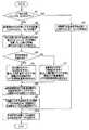
次に、立体モニタ4のおける上下左右の反転処理について、図10を用いて説明する。図10は、立体モニタ4のおける上下左右の反転処理の例を示すフローチャートである。 Next, the up / down / left / right reversing process in the
まず、上下左右反転スイッチ20aがONかOFFかが判定される(ステップS2)。上下左右反転スイッチ20aがOFFと判定された場合、映像信号が立体信号合成部24に入力されるように、セレクタ21及び23が動作する(ステップS2)。一方、上下左右反転スイッチ20aがONと判定された場合、映像信号が立体信号上下左右反転部22に入力されるように、セレクタ21が動作する(ステップS3)。なお、セレクタ23は、立体信号上下左右反転部22からの出力が立体信号合成部24に入力されるように動作する。 First, it is determined whether the up / down / left /
次に、対応点検出部34で左右画像の対応点を検出することにより、左右画像の視差(ズレ)と奥行き情報(画面の前か奥か)とを検出し(ステップS4)、奥行き情報は画面の前か否かが判定される(ステップS5)。奥行き情報が画面の前と判定された場合、YESとなり、左画像を左方向へ、右画像を右方向へ、検出した視差量だけ水平方向を移動させる制御信号を水平位置移動量算出部35が出力する(ステップS6)。一方、奥行き情報が画面の前でない、すなわち、画面の奥と判定された場合、NOとなり、左画像を右方向へ、右画像を左方向へ、検出した視差量だけ水平方向を移動させる制御信号を水平位置移動量算出部35が出力する(ステップS7)。 Next, the corresponding
次に、右画像移動部32a及び左画像移動部32bは、制御信号を受け、水平方向へ右画像及び左画像をシフトさせ(ステップS8)、右画像上下左右反転部33a及び左画像上下左右反転部33bは、右画像及び左画像の上下左右反転処理を行う(ステップS9)。最後に、立体信号合成部24で、左右画像を立体表示用のデータに合成し(ステップS10)、処理を終了する。 Next, the right
以上のように、立体内視鏡システム1は、右目用の映像信号と左目用の映像信号との視差及び奥行き情報を検出し、検出した視差及び奥行き情報に基づいて、右目用の映像信号及び左目用の映像信号の水平位置を移動する。その後、立体内視鏡システム1は、水平位置を移動した右目用の映像信号及び左目用の映像信号の上下左右を反転するようにした。この結果、立体内視鏡システム1は、右目用の映像信号及び左目用の映像信号を単純に上下左右を反転したときのように、奥行き情報が反転することがなくなり、正確な立体映像を表示することができる。 As described above, the
よって、本実施の形態の立体内視鏡システムよれば、立体映像を上下左右反転した場合でも、正確な立体映像を観察することができる。 Therefore, according to the stereoscopic endoscope system of the present embodiment, an accurate stereoscopic image can be observed even when the stereoscopic image is flipped up and down and left and right.
(第2の実施の形態)
次に、第2の実施の形態について説明する。(Second Embodiment)
Next, a second embodiment will be described.
第2の実施の形態は、第1の実施の形態の立体内視鏡システム1の立体モニタ4に代わり、立体モニタ4aを用いて構成されている。 The second embodiment is configured using a stereoscopic monitor 4a instead of the
図11は、立体モニタ4aの詳細な構成を説明するための図である。なお、図11において、図3と同様の構成については、同一の符号を付して説明を省略する。 FIG. 11 is a diagram for explaining a detailed configuration of the stereoscopic monitor 4a. In FIG. 11, the same components as those in FIG. 3 are denoted by the same reference numerals and description thereof is omitted.
図11に示すように、立体モニタ4aは、図3の立体モニタ4に対して分配器41と、立体映像信号生成部42と、信号出力部43とが追加されて構成されている。信号出力部43には、立体モニタや記録機器等の外部機器が接続される。分配器41、立体映像信号生成部42及び信号出力部43は、立体モニタ4aに表示される立体映像を、表示された立体映像と同じ状態で、かつ接続される外部機器が対応している立体映像フォーマットに合わせて出力するための信号処理系統である。 As shown in FIG. 11, the stereoscopic monitor 4 a is configured by adding a
分配器41は、立体表示パネル25の前段に設けられており、立体信号合成部24から出力された同じ出力信号を2系統、すなわち、立体表示パネル25及び立体映像信号生成部42に分配して出力する。このように、立体表示パネル25の直前で表示される信号を分配器41にて分配することで、分配する以前の信号処理で加えられた画質調整や位置調整が加えられた状態の立体画像を取り出すことができる。 The
変換部としての立体映像信号生成部42は、このように分配された立体画像を、外部機器の立体映像フォーマットに合わせるように変換し、信号出力部43に出力する。具体的には、立体映像信号生成部42は、外部機器の立体映像フォーマットに合わせて、例えば、立体映像フォーマットであるサイドバイサイド方式、または、フィールドシーケンシャル方式等の信号に変換し、信号出力部43に出力する。 The stereoscopic video
信号出力部43は、この変換された信号を、SDIやDVI等の映像出力信号に変換し、外部機器に出力する。 The
以上により、本実施の形態の立体内視鏡システム1は、立体モニタ4aの立体映像フォーマットとは異なる立体映像フォーマットの外部ききに、立体モニタ4aに表示される立体映像と同様の立体映像を表示または記録させることができる。 As described above, the
なお、本明細書における各フローチャート中の各ステップは、その性質に反しない限り、実行順序を変更し、複数同時に実行し、あるいは実行毎に異なった順序で実行してもよい。 It should be noted that the steps in the flowcharts in this specification may be executed in a different order for each execution by changing the execution order and performing a plurality of steps at the same time, as long as the steps are not contrary to the nature.
本発明は、上述した実施の形態及び変形例に限定されるものではなく、本発明の要旨を変えない範囲において、種々の変更、改変等が可能である。 The present invention is not limited to the above-described embodiments and modifications, and various changes and modifications can be made without departing from the scope of the present invention.
本出願は、2013年3月29日に日本国に出願された特願2013−73600号公報を優先権主張の基礎として出願するものであり、上記の開示内容は、本願明細書、請求の範囲、図面に引用されたものとする。 This application is filed on the basis of the priority claim of Japanese Patent Application No. 2013-73600 filed in Japan on March 29, 2013, and the above disclosure is disclosed in the present specification and claims. It shall be cited in the drawing.
Claims (4)
Translated fromJapanese前記立体内視鏡で取得された前記左右の撮像信号に所定の映像信号処理が施された左右の映像信号に応じた立体映像を表示する立体モニタと、
入力された前記左右の映像信号の右目用画像及び左目用画像中の被写体の位置を検出することにより左右画像の視差と奥行情報とを検出する対応点検出部と、
前記対応点検出部から出力された前記右目用画像及び前記左目用画像の位置から得られる前記右目用画像と前記左目用画像との視差と、前記立体映像の奥行情報とに基づき、前記左目用画像が前記立体モニタの画面の奥であるとき、前記左目用画像を右方向に視差量だけ、前記右目用画像に対しては左方向に視差量だけ水平移動させ、前記左目用画像が前記立体モニタの画面の手前であるとき、前記左目用画像を左方向に視差量だけ、前記右目用画像に対しては右方向に視差量だけ水平移動させる制御信号を出力する水平位置移動量算出部と、
前記水平位置移動量算出部により得られる制御信号を受けて前記左右の映像信号の水平位置を前記視差量だけ、前記奥行情報に応じて決定された方向にそれぞれ移動させる水平位置移動部と、
前記水平位置移動部で水平位置を移動された前記左右の映像信号の上下左右を反転させる上下左右反転部と、
前記上下左右反転部で上下左右を反転された前記左右の映像信号を合成して立体映像信号を生成する立体信号合成部と、
を有することを特徴とする立体内視鏡システム。A stereoscopic endoscope for acquiring left and right imaging signals;
A stereoscopic monitor for displaying a stereoscopic image corresponding to the left and right video signals obtained by performing predetermined video signal processing on the left and right imaging signals acquired by the stereoscopic endoscope;
A corresponding point detection unit that detects the parallax and depth information of the left and right images by detecting the position of the subject in the right-eye image and the left-eye image of the input left and right video signals;
Based on the parallax between the right-eye image and the left-eye image obtained from the positions of the right-eye image and the left-eye image output from the corresponding point detection unit, and the depth information of the stereoscopic video, the left-eye image When the image is behindthe screen of the stereoscopicmonitor, the left-eye image is horizontally moved by the amount of parallax in the right direction, and the right-eye image is horizontally moved by the amount of parallax in the left direction. A horizontal position movement amount calculation unit that outputs a control signal for horizontally moving the left-eye image by a parallax amount in the left direction and the right-eye image by a parallax amount in the right direction when the image is in front of themonitor screen ; ,
Only the amount of parallax in the horizontal position of the video signal of the left and right in response to a control signal obtained by the horizontal position movement amount calculating section, and the horizontal position moving unit that moves each direction determined according to the innerGyojo paper,
An up / down / left / right inversion unit for inverting the up / down / left / right of the left and right video signals moved in the horizontal position by the horizontal position moving unit;
A stereoscopic signal synthesis unit that generates a stereoscopic video signal by synthesizing the left and right video signals inverted up and down and left and right by the up and down left and right inversion unit;
A stereoscopic endoscope system characterized by comprising:
Priority Applications (1)
| Application Number | Priority Date | Filing Date | Title |
|---|---|---|---|
| JP2014544286AJP5771754B2 (en) | 2013-03-29 | 2013-11-12 | Stereoscopic endoscope system |
Applications Claiming Priority (4)
| Application Number | Priority Date | Filing Date | Title |
|---|---|---|---|
| JP2013073600 | 2013-03-29 | ||
| JP2013073600 | 2013-03-29 | ||
| JP2014544286AJP5771754B2 (en) | 2013-03-29 | 2013-11-12 | Stereoscopic endoscope system |
| PCT/JP2013/080504WO2014155815A1 (en) | 2013-03-29 | 2013-11-12 | Stereoscopic endoscope system |
Publications (2)
| Publication Number | Publication Date |
|---|---|
| JP5771754B2true JP5771754B2 (en) | 2015-09-02 |
| JPWO2014155815A1 JPWO2014155815A1 (en) | 2017-02-16 |
Family
ID=51622852
Family Applications (1)
| Application Number | Title | Priority Date | Filing Date |
|---|---|---|---|
| JP2014544286AActiveJP5771754B2 (en) | 2013-03-29 | 2013-11-12 | Stereoscopic endoscope system |
Country Status (5)
| Country | Link |
|---|---|
| US (1) | US9408528B2 (en) |
| EP (1) | EP2945375A4 (en) |
| JP (1) | JP5771754B2 (en) |
| CN (1) | CN105009581B (en) |
| WO (1) | WO2014155815A1 (en) |
Families Citing this family (6)
| Publication number | Priority date | Publication date | Assignee | Title |
|---|---|---|---|---|
| JP2013016116A (en)* | 2011-07-06 | 2013-01-24 | Sony Corp | Information processing device, image display apparatus, and information processing method |
| EP3318177B1 (en)* | 2015-08-06 | 2020-11-04 | Sony Olympus Medical Solutions Inc. | Medical signal-processing device, medical display device, and medical observation system |
| CN105361842A (en)* | 2015-10-28 | 2016-03-02 | 李京 | 3D endoscope breast augmentation technique |
| US10609354B2 (en)* | 2016-02-12 | 2020-03-31 | Sony Corporation | Medical image processing device, system, method, and program |
| US20200175656A1 (en)* | 2017-07-12 | 2020-06-04 | Sony Corporation | Image processing apparatus, ophthalmic observation apparatus, and ophthalmic observation system |
| CN117915853A (en)* | 2021-09-10 | 2024-04-19 | 阿瑙特株式会社 | Inference device, information processing method, and computer program |
Family Cites Families (10)
| Publication number | Priority date | Publication date | Assignee | Title |
|---|---|---|---|---|
| JP3431983B2 (en)* | 1994-04-01 | 2003-07-28 | オリンパス光学工業株式会社 | Image processing device |
| JP3488060B2 (en)* | 1997-11-12 | 2004-01-19 | 株式会社Pfu | Heat dissipation device for thin electronic devices |
| JP2001078174A (en)* | 1999-09-03 | 2001-03-23 | Olympus Optical Co Ltd | Image processor |
| JP2001272760A (en) | 2000-03-24 | 2001-10-05 | Konica Corp | Automatic developing device for silver halide photographic sensitive material |
| WO2004084559A1 (en) | 2003-03-20 | 2004-09-30 | Seijiro Tomita | Video display for vehicle |
| JP2006284877A (en)* | 2005-03-31 | 2006-10-19 | Olympus Medical Systems Corp | Medical stereoscopic image display control device |
| JP4598717B2 (en)* | 2006-05-09 | 2010-12-15 | オリンパスメディカルシステムズ株式会社 | Observation system and observation video signal transmission method |
| JP5430565B2 (en)* | 2008-06-18 | 2014-03-05 | パナソニック株式会社 | Electronic mirror device |
| JP5259457B2 (en)* | 2009-03-03 | 2013-08-07 | オリンパスメディカルシステムズ株式会社 | Electronic image observation device |
| JP2012053165A (en)* | 2010-08-31 | 2012-03-15 | Sony Corp | Information processing device, program, and information processing method |
- 2013
- 2013-11-12JPJP2014544286Apatent/JP5771754B2/enactiveActive
- 2013-11-12CNCN201380073806.7Apatent/CN105009581B/enactiveActive
- 2013-11-12EPEP13879902.8Apatent/EP2945375A4/ennot_activeCeased
- 2013-11-12WOPCT/JP2013/080504patent/WO2014155815A1/enactiveApplication Filing
- 2014
- 2014-10-01USUS14/504,054patent/US9408528B2/enactiveActive
Also Published As
| Publication number | Publication date |
|---|---|
| CN105009581A (en) | 2015-10-28 |
| CN105009581B (en) | 2017-03-08 |
| US9408528B2 (en) | 2016-08-09 |
| EP2945375A1 (en) | 2015-11-18 |
| WO2014155815A1 (en) | 2014-10-02 |
| EP2945375A4 (en) | 2016-06-15 |
| JPWO2014155815A1 (en) | 2017-02-16 |
| US20150085074A1 (en) | 2015-03-26 |
Similar Documents
| Publication | Publication Date | Title |
|---|---|---|
| JP5771754B2 (en) | Stereoscopic endoscope system | |
| JP6655756B2 (en) | 3D endoscope device and 3D image processing device | |
| JP5893808B2 (en) | Stereoscopic endoscope image processing device | |
| US20160295194A1 (en) | Stereoscopic vision system generatng stereoscopic images with a monoscopic endoscope and an external adapter lens and method using the same to generate stereoscopic images | |
| US20140293007A1 (en) | Method and image acquisition system for rendering stereoscopic images from monoscopic images | |
| CN104185441B (en) | Stereo Vision Endoscopy System | |
| JP6296365B2 (en) | Surgical endoscope camera control unit | |
| JP6912313B2 (en) | Image processing device, camera device and image processing method | |
| JP5629023B2 (en) | Medical three-dimensional observation device | |
| JP5851656B2 (en) | Image signal output apparatus and image signal transmission / reception system | |
| JP6884607B2 (en) | Medical image display device, medical information processing system, and medical image display control method | |
| JP2015220643A (en) | Stereoscopic observation device | |
| EP3247113B1 (en) | Image processing device, image processing method, program, and endoscope system | |
| CN115919239A (en) | Imaging method for 3D endoscopic imaging system and 3D endoscopic imaging system | |
| CN115299914A (en) | Endoscope system, image processing method and device | |
| US10855980B2 (en) | Medical-image display control device, medical image display device, medical-information processing system, and medical-image display control method | |
| JP5818265B2 (en) | Stereoscopic endoscope device | |
| JP4594673B2 (en) | Display control device for stereoscopic endoscope | |
| JP2011234788A (en) | Ultrasonic diagnostic system, ultrasonic image processing method, and ultrasonic image processing program | |
| JP7393842B1 (en) | Support system, support device, supported device | |
| JP7401157B1 (en) | Support system, support device, supported device | |
| JP6021215B2 (en) | Stereoscopic video recording apparatus, stereoscopic video display apparatus, and stereoscopic video recording system using them | |
| JP2004233480A (en) | Stereoscopic endoscope system | |
| JPH08275206A (en) | Stereoscopic image display device | |
| JP2012189689A (en) | Photographed image composition and display device, and image composition and presentation system |
Legal Events
| Date | Code | Title | Description |
|---|---|---|---|
| TRDD | Decision of grant or rejection written | ||
| A01 | Written decision to grant a patent or to grant a registration (utility model) | Free format text:JAPANESE INTERMEDIATE CODE: A01 Effective date:20150603 | |
| RD03 | Notification of appointment of power of attorney | Free format text:JAPANESE INTERMEDIATE CODE: A7423 Effective date:20150525 | |
| A61 | First payment of annual fees (during grant procedure) | Free format text:JAPANESE INTERMEDIATE CODE: A61 Effective date:20150629 | |
| R151 | Written notification of patent or utility model registration | Ref document number:5771754 Country of ref document:JP Free format text:JAPANESE INTERMEDIATE CODE: R151 | |
| S531 | Written request for registration of change of domicile | Free format text:JAPANESE INTERMEDIATE CODE: R313531 | |
| R350 | Written notification of registration of transfer | Free format text:JAPANESE INTERMEDIATE CODE: R350 | |
| R250 | Receipt of annual fees | Free format text:JAPANESE INTERMEDIATE CODE: R250 | |
| R250 | Receipt of annual fees | Free format text:JAPANESE INTERMEDIATE CODE: R250 | |
| R250 | Receipt of annual fees | Free format text:JAPANESE INTERMEDIATE CODE: R250 | |
| R250 | Receipt of annual fees | Free format text:JAPANESE INTERMEDIATE CODE: R250 | |
| R250 | Receipt of annual fees | Free format text:JAPANESE INTERMEDIATE CODE: R250 | |
| R250 | Receipt of annual fees | Free format text:JAPANESE INTERMEDIATE CODE: R250 |