JP5770876B1 - MMIC integrated module - Google Patents
MMIC integrated moduleDownload PDFInfo
- Publication number
- JP5770876B1 JP5770876B1JP2014065090AJP2014065090AJP5770876B1JP 5770876 B1JP5770876 B1JP 5770876B1JP 2014065090 AJP2014065090 AJP 2014065090AJP 2014065090 AJP2014065090 AJP 2014065090AJP 5770876 B1JP5770876 B1JP 5770876B1
- Authority
- JP
- Japan
- Prior art keywords
- mmic
- antenna
- integrated module
- cavity
- dielectric
- Prior art date
- Legal status (The legal status is an assumption and is not a legal conclusion. Google has not performed a legal analysis and makes no representation as to the accuracy of the status listed.)
- Expired - Fee Related
Links
Images


Classifications
- H—ELECTRICITY
- H01—ELECTRIC ELEMENTS
- H01L—SEMICONDUCTOR DEVICES NOT COVERED BY CLASS H10
- H01L2223/00—Details relating to semiconductor or other solid state devices covered by the group H01L23/00
- H01L2223/58—Structural electrical arrangements for semiconductor devices not otherwise provided for
- H01L2223/64—Impedance arrangements
- H01L2223/66—High-frequency adaptations
- H01L2223/6661—High-frequency adaptations for passive devices
- H01L2223/6677—High-frequency adaptations for passive devices for antenna, e.g. antenna included within housing of semiconductor device
- H—ELECTRICITY
- H01—ELECTRIC ELEMENTS
- H01L—SEMICONDUCTOR DEVICES NOT COVERED BY CLASS H10
- H01L2224/00—Indexing scheme for arrangements for connecting or disconnecting semiconductor or solid-state bodies and methods related thereto as covered by H01L24/00
- H01L2224/01—Means for bonding being attached to, or being formed on, the surface to be connected, e.g. chip-to-package, die-attach, "first-level" interconnects; Manufacturing methods related thereto
- H01L2224/10—Bump connectors; Manufacturing methods related thereto
- H01L2224/15—Structure, shape, material or disposition of the bump connectors after the connecting process
- H01L2224/16—Structure, shape, material or disposition of the bump connectors after the connecting process of an individual bump connector
- H01L2224/161—Disposition
- H01L2224/16151—Disposition the bump connector connecting between a semiconductor or solid-state body and an item not being a semiconductor or solid-state body, e.g. chip-to-substrate, chip-to-passive
- H01L2224/16221—Disposition the bump connector connecting between a semiconductor or solid-state body and an item not being a semiconductor or solid-state body, e.g. chip-to-substrate, chip-to-passive the body and the item being stacked
- H01L2224/16225—Disposition the bump connector connecting between a semiconductor or solid-state body and an item not being a semiconductor or solid-state body, e.g. chip-to-substrate, chip-to-passive the body and the item being stacked the item being non-metallic, e.g. insulating substrate with or without metallisation
- H01L2224/16227—Disposition the bump connector connecting between a semiconductor or solid-state body and an item not being a semiconductor or solid-state body, e.g. chip-to-substrate, chip-to-passive the body and the item being stacked the item being non-metallic, e.g. insulating substrate with or without metallisation the bump connector connecting to a bond pad of the item
- H—ELECTRICITY
- H01—ELECTRIC ELEMENTS
- H01L—SEMICONDUCTOR DEVICES NOT COVERED BY CLASS H10
- H01L2224/00—Indexing scheme for arrangements for connecting or disconnecting semiconductor or solid-state bodies and methods related thereto as covered by H01L24/00
- H01L2224/01—Means for bonding being attached to, or being formed on, the surface to be connected, e.g. chip-to-package, die-attach, "first-level" interconnects; Manufacturing methods related thereto
- H01L2224/42—Wire connectors; Manufacturing methods related thereto
- H01L2224/47—Structure, shape, material or disposition of the wire connectors after the connecting process
- H01L2224/48—Structure, shape, material or disposition of the wire connectors after the connecting process of an individual wire connector
- H01L2224/481—Disposition
- H01L2224/48151—Connecting between a semiconductor or solid-state body and an item not being a semiconductor or solid-state body, e.g. chip-to-substrate, chip-to-passive
- H01L2224/48221—Connecting between a semiconductor or solid-state body and an item not being a semiconductor or solid-state body, e.g. chip-to-substrate, chip-to-passive the body and the item being stacked
- H01L2224/48245—Connecting between a semiconductor or solid-state body and an item not being a semiconductor or solid-state body, e.g. chip-to-substrate, chip-to-passive the body and the item being stacked the item being metallic
- H01L2224/48247—Connecting between a semiconductor or solid-state body and an item not being a semiconductor or solid-state body, e.g. chip-to-substrate, chip-to-passive the body and the item being stacked the item being metallic connecting the wire to a bond pad of the item
- H—ELECTRICITY
- H01—ELECTRIC ELEMENTS
- H01L—SEMICONDUCTOR DEVICES NOT COVERED BY CLASS H10
- H01L2924/00—Indexing scheme for arrangements or methods for connecting or disconnecting semiconductor or solid-state bodies as covered by H01L24/00
- H01L2924/15—Details of package parts other than the semiconductor or other solid state devices to be connected
- H01L2924/151—Die mounting substrate
- H01L2924/153—Connection portion
- H01L2924/1532—Connection portion the connection portion being formed on the die mounting surface of the substrate
- H01L2924/15321—Connection portion the connection portion being formed on the die mounting surface of the substrate being a ball array, e.g. BGA
Landscapes
- Aerials With Secondary Devices (AREA)
- Variable-Direction Aerials And Aerial Arrays (AREA)
- Waveguide Aerials (AREA)
Abstract
Translated fromJapaneseDescription
Translated fromJapanese本発明は、ミリ波帯又はテラヘルツ波帯の無線通信に用いるMMIC(monolithic microwave integrated circuit:モノシリックマイクロ波集積回路)を実装したMMIC集積モジュールの技術に関する。 The present invention relates to a technology of an MMIC integrated module on which an MMIC (monolithic microwave integrated circuit) used for millimeter wave band or terahertz wave wireless communication is mounted.
旧来より、ミリ波又はテラヘルツ波の高周波RF(radio frequency)信号を扱うICパッケージが開発されている。このICパッケージは電磁波を入力するための導波管ポートを備えた金属体であり、金属表面には酸化防止の金メッキが形成されている。また、導波管フランジも形成されており、アライメント用のピンや固定ボルト等を必要とするため、サイズが大きく高コストとなってしまう。 Traditionally, IC packages that handle high-frequency RF (radio frequency) signals of millimeter waves or terahertz waves have been developed. This IC package is a metal body provided with a waveguide port for inputting electromagnetic waves, and an anti-oxidation gold plating is formed on the metal surface. In addition, a waveguide flange is also formed, which requires alignment pins, fixing bolts, and the like, resulting in a large size and high cost.
そこで近年では、製造上の高コスト化を抑制するため、誘電性の基板を積層させ、その積層過程において各基板にビアを形成したり基板表面に金属線を配線したりすることにより、旧来よりも簡易にICパッケージを含むMMIC集積モジュールを生成する手法が提案されている(非特許文献1)。 Therefore, in recent years, in order to suppress high manufacturing costs, dielectric substrates are laminated, and vias are formed in each substrate in the lamination process, or metal wires are wired on the substrate surface, and so on. In addition, a method for easily generating an MMIC integrated module including an IC package has been proposed (Non-Patent Document 1).
この非特許文献1に記載されたFig.1を図7に示す。このMMIC集積モジュール100は、複数の誘電性基板1’を積層し、積層させた誘電性基板群の一部でキャビティ7を形成し、そのキャビティ7の上壁面の表面に平面型のアンテナ10を配置することにより、形成されている。 Fig. 1 described in this Non-Patent
また、誘電性基板1’の表面には、MMIC集積モジュール100の外部からキャビティ7内のアンテナ10へ信号を伝達するためのアンテナフィード線21やアンテナグランド線22が配設され、RFIC23に低周波信号を供給するための信号線24やRFIC23用のグランド線25も更に配設されている。RFIC23は、誘電性基板群の外部裏表面に配置され、信号線24を介して低周波信号を受信し、その低周波信号を用いて高周波RF信号を生成して、アンテナフィード線21を介してアンテナ10から出力する。 On the surface of the
このようなMMIC集積モジュール100において、RFIC23は、ワイヤボンディング又はフリップチップボンディングにより誘電性基板群の外部裏表面にマウント実装されている。かかる構成より、RFIC23からの高周波RF信号は図示しないボンディングやワイヤを介してアンテナ10に到達するため、高周波RF信号の信号損失が大きくなってしまう。その結果、高周波RF信号の送信側と受信側のそれぞれにおいて、信号パワーやノイズフィギュア等の特性劣化が生じることになる。 In such an MMIC integrated
そのため、RFICの上にアンテナを一体的に形成する手法も提案されている。図8は、2つ目の従来のMMIC集積モジュール100の構成を示す図である。このMMIC集積モジュールは、金属筐体31の内部に形成されたキャビティ7の底面にシリコン基板32を埋め込み、そのシリコン基板32のキャビティ7側の表面にRFICを有するMMICチップ2と回路の実装基板33を配置し、そのMMICチップ2の表面にアンテナ10を形成している。また、シリコン基板32の他方の表面に半球状のシリコンレンズ3’’をダイボンディング接合し、そのシリコンレンズ3’’の球部の一部を金属筐体31から外部へ突出するように配置している。 Therefore, a method of integrally forming an antenna on the RFIC has been proposed. FIG. 8 is a diagram showing a configuration of a second conventional MMIC integrated
かかる構成より、MMICチップ2の上にアンテナ10が形成されているため、高周波RF信号の信号損失を抑制することができる。また、MMICチップ2に対して、そのMMICチップ2の化合物半導体材料と誘電率が近いシリコンからなるシリコン基板32とシリコンレンズ3’’を接合しているため、アンテナ10からの電波を効率良く空気中に放射することができる。 With this configuration, since the
特に高抵抗シリコンは、テラヘルツ帯の領域において誘電体損失が無く、レンズやプリズムの材料として一般的に用いられている。また、シリコンレンズ3’’の半径やシリコン基板32の厚さを適切に設計することにより、ガウシアン性の良い放射パターンや高利得特性を得ることができる(特許文献1)。 In particular, high-resistance silicon has no dielectric loss in the terahertz band region and is generally used as a material for lenses and prisms. Further, by appropriately designing the radius of the
なお、このMMIC集積モジュール100は、外部からの信号を受信可能である。アンテナ10で受信した信号は、ワイヤ34で接続された実装基板33を経由して信号端子35へ出力され、データ信号線36を通じて外部へ出力される。 The MMIC integrated
しかしながら、図8に示したMMIC集積モジュールでは、MMIC上のアンテナからの電波がシリコンレンズ側と金属筐体のキャビティ側の両方に放射するため、キャビティ側に放射された電磁波は損失となってしまい、アンテナ効率や利得が低下し、更にはMMICチップ上の電気線路に再結合することにより増幅器等の回路で発振現象が発生するという課題があった。 However, in the MMIC integrated module shown in FIG. 8, since the radio wave from the antenna on the MMIC radiates to both the silicon lens side and the cavity side of the metal housing, the electromagnetic wave radiated to the cavity side is lost. However, there has been a problem that the antenna efficiency and the gain are lowered, and further, an oscillation phenomenon occurs in a circuit such as an amplifier by recombination with an electric line on the MMIC chip.
本発明は、上記事情を鑑みてなされたものであり、電波の放射効率を改善することを目的とする。 The present invention has been made in view of the above circumstances, and an object thereof is to improve radio wave radiation efficiency.
以上の課題を解決するため、請求項1に記載のMMIC集積モジュールは、ミリ波又はテラヘルツ波用のMMIC集積モジュールにおいて、キャビティを形成するように積み重ねられた複数の誘電性基板と、前記キャビティの開口面に配置された誘電性レンズと、アンテナの形成面が前記キャビティの底面に向かい合うように前記キャビティの内部に配置されたMMICチップと、前記アンテナに対向するように誘電性基板の表面に形成された金属層と、前記アンテナを囲むように配置された複数の金属体と、前記金属層を囲むように前記誘電性基板に形成された複数のビアと、を有し、前記複数のビアは、前記複数の金属体の配置と同じ位置で前記誘電性基板に形成されていることを要旨とする。In order to solve the above problems, an MMIC integrated module according to
本発明によれば、MMICチップ上のアンテナに対向するように金属層を形成しているため、アンテナからキャビティの内部側に放射される電波を誘電体レンズのある方向へ反射できることから、電波を効率的に放射することができる。 According to the present invention, since the metal layer is formed so as to face the antenna on the MMIC chip, the radio wave radiated from the antenna to the inner side of the cavity can be reflected in the direction of the dielectric lens. It can radiate efficiently.
本発明によれば、アンテナを複数の金属体で囲むように構成しているため、大気中への放射を抑制できることから、電波をより効率的に放射することができる。また、本発明によれば、金属層を複数のビアで囲むように構成しているため、大気中への放射を抑制できることから、電波をより効率的に放射することができる。According to the present invention, since the antenna is configured to be surrounded by a plurality of metal bodies, radiation into the atmosphere can be suppressed, so that radio waves can be radiated more efficiently.Further, according to the present invention, since the metal layer is configured to be surrounded by a plurality of vias, radiation into the atmosphere can be suppressed, so that radio waves can be radiated more efficiently.
請求項2に記載のMMIC集積モジュールは、請求項1に記載のMMIC集積モジュールにおいて、前記金属体は、前記MMICチップを前記キャビティの底面にフリップチップ実装するためのバンプであることを要旨とする。The MMIC integrated module according to
請求項3に記載のMMIC集積モジュールは、請求項1又は2に記載のMMIC集積モジュールにおいて、前記アンテナと前記金属層との間に位置する誘電性基板に形成された空孔を更に有することを要旨とする。The MMIC integrated module according to
請求項4に記載のMMIC集積モジュールは、請求項1乃至3のいずれかに記載のMMIC集積モジュールにおいて、前記誘電性レンズは、前記キャビティ側の表面に凸レンズを有することを要旨とする。The MMIC integrated module according to
請求項5に記載のMMIC集積モジュールは、請求項1乃至4のいずれかに記載のMMIC集積モジュールにおいて、前記金属層は、接地していることを要旨とする。The MMIC integrated module according to
本発明によれば、電波を効率的に放射できる。 According to the present invention, radio waves can be radiated efficiently.
本発明は、アンテナを形成したMMICチップをフリップチップ実装するMMIC集積モジュールにおいて、(1)MMICチップ上のアンテナに対して対向するように誘電性基板上に金属層を形成し、(2)その金属層を囲むようにビアを形成し、(3)そのアンテナを囲むようにMMICチップと誘電性基板を接合する金属体を配置するようにしている。以下、本発明を実施する一実施の形態について図面を用いて説明する。 The present invention provides an MMIC integrated module in which an MMIC chip having an antenna formed thereon is flip-chip mounted. (1) A metal layer is formed on a dielectric substrate so as to face the antenna on the MMIC chip, and (2) Vias are formed so as to surround the metal layer, and (3) a metal body for joining the MMIC chip and the dielectric substrate is arranged so as to surround the antenna. Hereinafter, an embodiment for carrying out the present invention will be described with reference to the drawings.
〔第1の実施の形態〕
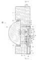
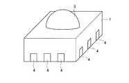
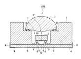
図1は、第1の実施の形態に係るMMIC集積モジュール100の断面図である。図2は、そのMMIC集積モジュール100の斜視図である。本MMIC集積モジュール100は、多層型誘電性基板パッケージ1と、MMICチップ2と、レンズ3とを主に備えて構成される。[First Embodiment]
FIG. 1 is a cross-sectional view of an MMIC integrated
多層型誘電性基板パッケージ1は、セラミックやLTCC(Low Temperature Co-fired Ceramics)等の誘電性基板を積層することにより形成される。任意の誘電性基板には、その表面において、多層型誘電性基板パッケージ1の外表面に形成・配置された外部電極4に接続される配線5が形成され、更に誘電性基板間を導通するビア6が形成される。また、最上及び中間に位置する複数の誘電性基板を用いて凹形状の内部空間(キャビティ)7が形成され、そのキャビティ7の底面の上に、配線5及びビア6を介して外部電極4に電気的に接続される内部電極8が形成・配置される。 The multilayer
MMICチップ2は、多層型誘電性基板パッケージ1のキャビティ7に収まるサイズで形成され、そのキャビティ7の底面の上にフリップチップ実装される。例えば、金属性の接合用ボール9を用いて、キャビティ7内の内部電極8に電気的に接続する。MMICチップ2の表面には、図示しないRFIC(Radio Frequency Integrated Circuit)が形成され、更にオンチップ型のアンテナ10が形成されている。また、そのアンテナ10の形成面がキャビティ7の底面に向かい合うようにフリップチップ実装される。かかる構造により、外部電極4からの低周波信号を配線5,ビア6,内部電極8,接合用ボール9を介して受信し、その低周波信号を用いてRFICで高周波RF信号を生成し、その高周波RF信号の電波をアンテナ10から放射する。図1の場合、アンテナ10から上側と下側へ放射される。また、外部からの高周波RF信号をアンテナ10で受信し、同様の経路を逆に辿り外部電極4へ出力することも可能である。 The
レンズ3は、半球状の形を有し、電磁波の波長の数倍以上ある径を有する。例えば、シリコン,テフロン,ポリエチレン、石英等の誘電性レンズを用いて形成される。接着剤11やUV樹脂等を用いてキャビティ7の開口面に配置され、固定される。その際、電磁波の放射パターンの中心軸がレンズ3の中心軸と一致するように配置することが好ましい。また、光学的に透明な材料をレンズ材料に用いることが好ましい。これにより、目視により、MMICチップ2やアンテナ10の位置との位置合わせが可能となり、実装も容易となる。また、シリコンを用いる場合には、例えば10kΩ・cm以上の高抵抗シリコンを用いることが好ましい。これにより、ガウシアン性の良い放射パターンや高利得特性を得ることができる。また、レンズ3の周縁を支える誘電性基板を変更したり、接合用ボール9のサイズを調整したりすることにより、そのキャビティ7に収容されるMMICチップ2に直接接合させることが好ましい。 The
このような構成要素を備えたMMIC集積モジュール100において、本実施の形態では、アンテナ10と対向する誘電性基板の表面(キャビティ7の底面)に金属性の反射板12を形成する。例えば、キャビティ7の底面に位置する誘電性基板の一部を切除等することにより、アンテナ10の存在する位置において深さd×幅wの小キャビティ7’を形成し、その小キャビティ7’の底面の上を金属層で覆うようにする。 In the MMIC
このように、小キャビティ7’の底面に金属層を形成することにより、アンテナ10から小キャビティ7’側へ放射された電波を反対方向へ反射させことができる。なお、小キャビティ7’の深さdとは、MMICチップ2のアンテナ形成面と小キャビティ7’の底面との間の距離であり、例えば、使用する帯域の中心波長λの1/6〜1/3の範囲内が好ましい。また、形成された金属層を接地するようにしても構わない。これにより、電波の反射効率を高めることができる。 Thus, by forming a metal layer on the bottom surface of the
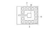
また、本実施の形態では、反射板12を複数のビア6で囲むように形成・配置し、更にアンテナ10を複数の接合用ボール9で囲むように形成・配置する。例えば、接合用ボール9を小キャビティ7’の側壁面の一部として用いるようにする。図1のX−X’断面の一部を下から上に見た図を図3に示す。図3では、MMICチップ2上のアンテナ10と接合用ボール9との配置状態を示している。MMICチップ2のアンテナ形成面には、アンテナ10を囲むように金属層13が形成され、この金属層13の上に所定の間隔で接合用ボール9を配置する。更に、図1に示したように、図3のように配置された複数の接合用ボール9と同じ配置状態となるように複数のビア6を形成し、反射板12を囲むようにする。 In this embodiment, the
このように、アンテナ10を囲むように複数の接合用ボール9を配置し、反射板12を囲むように複数のビア6を形成することにより、アンテナ10から小キャビティ7’側へ放射された電波が水平方向へ分散することを防止できる。なお、接合用ボール9の間隔やビア6の間隔は、使用する帯域の中心波長λの1/4以下が好ましい。また、金属層13を接地し、その金属層13上の接合用ボール9や当該接合用ボール8に電気的に接続されるビア6をRFICのアース用電極の一部として用いるようにしても構わない。 In this way, by arranging the plurality of
本実施の形態によれば、MMICチップ2上のアンテナ10と対向するように小キャビティ7’の底面に反射板12を形成し、その反射板12を囲むように複数のビア6を形成し、更にアンテナ10を囲むように複数の接合用ボール9を配置するので、アンテナ10から小キャビティ7’側へ放射された電波を反対方向のみに反射することが可能となり、MMIC集積モジュール100から電波を効率的に放射することができる。 According to the present embodiment, the reflecting
〔第2の実施の形態〕
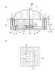
図4は、第2の実施の形態に係るMMIC集積モジュール100を示す図である。同図(a)は、MMIC集積モジュール100の断面図である。同図(b)は、同図(a)のX−X’断面を上から下に見た図である。[Second Embodiment]
FIG. 4 is a diagram illustrating the MMIC
本MMIC集積モジュール100は、第1の実施の形態と同様に、図示しない導体層が表面に形成された誘電体層(第1の実施の形態における誘電性基板)1’を積層することにより多層型誘電性基板パッケージ1を形成する。また、ビア6を形成した誘電体層1’を積層することにより、MMICチップ2を格納する長方形のキャビティ7を形成する。 Similar to the first embodiment, the MMIC
キャビティ7を構成する最上の誘電体層1’に形成されたビア6aのサイズは他のビア6bのサイズと異なり、最上及びその下の誘電体層1’による枠部をステップ状とし、レンズ3を実装する。なお、誘電体層1’の材料は、セラミックスやガラスフィラーを混入したセラミックス混合材料、ポリイミド等のポリマー材料でもよいが、誘電損失が小さい材料が好ましい。セラミックス材料を用いた場合には、誘電体層1’を積層した後に高温で焼成を行う。誘電体層1’の厚さは数〜数十ミクロンであり、シルクスクリーン印刷やメッキ処理により形成する。一方、導体層の材料は、金、銀、タングステン、銅などでもよい。 The size of the via 6a formed in the uppermost dielectric layer 1 'constituting the
本実施の形態では、第1の実施の形態と異なり、バンプ9’を用いてMMICチップ2をキャビティ7の底面にフリップチップ実装する。また、小キャビティ7’を形成することなく、反射板12をバンプ9’の実装面と同一平面に形成する。アンテナ10から反射板12までの距離は、第1の実施の形態と同様に、例えば、使用する帯域の中心波長λの1/6〜1/3の範囲内とする。 In the present embodiment, unlike the first embodiment, the
本実施の形態によれば、MMICチップ2のアンテナ10と対向するように、キャビティ7の底面に反射板12を形成し、そのアンテナ10を囲むように複数のバンプ9’を配置するので、アンテナ10から小キャビティ7’側へ放射された電波を反対方向のみに反射することが可能となり、MMIC集積モジュール100から電波を効率的に放射することができる。 According to the present embodiment, the
〔第3の実施の形態〕
図5は、第3の実施の形態に係るMMIC集積モジュール100を示す図である。同図(a)は、MMIC集積モジュール100の断面図である。同図(b)は、同図(a)のX−X’断面の一部を上から下に見た図である。以下、第1,2の実施の形態との相違点を中心に説明する。[Third Embodiment]
FIG. 5 is a diagram showing an MMIC
本実施の形態では、第1,2の実施の形態と異なり、反射板12をバンプ9’の実装面(誘電体層1a’)の下の誘電体層1b’の表面に形成し、その反射板12の上に位置する誘電体層1a’に複数の空孔14を形成し、その空孔14を囲むように複数のビア6を形成する。また、その複数のビア6の形成位置に沿うように誘電体層1a’の表面に金属層15を凹状に形成し、その金属層15の上にMMICチップ2をフリップチップ実装する。図5(b)では、金属層15の形成パターン、空孔14の配置パターン、ビア6の配置パターンの各例を示している。 In the present embodiment, unlike the first and second embodiments, the reflecting
第1の実施の形態では、誘電性基板の一部を排除することにより、小キャビティ7’の深さを制御している。しかし、これによりMMIC集積モジュール100の底面の厚さが薄くなるため、物理的強度が弱くなり、誘電性基板の反りが大きくなる可能性がある。これに対し、本実施の形態では、削除対象であった誘電性基板1a’の該当部分に空孔14を形成しているので、MMIC集積モジュール1の物理的な強度が高くなり、等価的に誘電率を制御してキャビティの深さを実質的に制御することができる。 In the first embodiment, the depth of the small cavity 7 'is controlled by eliminating a part of the dielectric substrate. However, the thickness of the bottom surface of the MMIC
〔第4の実施の形態〕
図6は、第4の実施の形態に係るMMIC集積モジュール100の断面図である。本実施の形態では、レンズ3の材料として、特に、テフロン,ポリエチレン,石英等の低誘電率の誘電体を使用し、レンズ3の下面に凸レンズ3’を形成している。これにより、アンテナ10から放射される電波の放射パターンを適切に制御することができ、アンテナ利得を向上することができる。[Fourth Embodiment]
FIG. 6 is a cross-sectional view of the MMIC
以上より、第1〜第4の実施の形態によれば、MMICチップ2上のアンテナ10と対向するようにキャビティ7又は小キャビティ7’の底面に反射板12を形成・配置したので、アンテナ10から電波を効率的に放射でき、電波の損失を低減でき、結果としてアンテナ効率と利得を改善することができる。また、アンテナ10を囲むように接合用ボール9又はバンプ9’を配置し、反射板12を囲むようにビア6を形成したので、大気中への放射を抑制し、MMICチップ上に形成された増幅器等の発振を防止することができる。 As described above, according to the first to fourth embodiments, the reflecting
1…MMIC集積モジュール
1’…誘電体層(誘電性基板)
2…MMICチップ
3…レンズ
3’…凸レンズ
3’’…シリコンレンズ
4…外部電極
5…配線
6…ビア
7…キャビティ
7’…小キャビティ
8…内部電極
9…接合用ボール
9’…バンプ
10…アンテナ
11…接着剤
12…反射板
13…金属層
14…空孔
15…金属層
21…アンテナフィード線
22…アンテナグランド線
23…RFIC
24…信号線
25…グランド線
31…金属筐体
32…シリコン基板
33…実装基板
34…ワイヤ
35…信号端子
36…データ信号線1 ... MMIC integrated module 1 '... Dielectric layer (dielectric substrate)
2 ...
24 ...
Claims (5)
Translated fromJapaneseキャビティを形成するように積み重ねられた複数の誘電性基板と、
前記キャビティの開口面に配置された誘電性レンズと、
アンテナの形成面が前記キャビティの底面に向かい合うように前記キャビティの内部に配置されたMMICチップと、
前記アンテナに対向するように誘電性基板の表面に形成された金属層と、
前記アンテナを囲むように配置された複数の金属体と、
前記金属層を囲むように前記誘電性基板に形成された複数のビアと、を有し、
前記複数のビアは、
前記複数の金属体の配置と同じ位置で前記誘電性基板に形成されていることを特徴とするMMIC集積モジュール。In the MMIC integrated module for millimeter wave or terahertz wave,
A plurality of dielectric substrates stacked to form a cavity;
A dielectric lens disposed on an opening surface of the cavity;
An MMIC chip disposed inside the cavity such that an antenna forming surface faces the bottom surface of the cavity;
A metal layer formed on the surface of the dielectric substrate so as to face the antenna;
A plurality of metal bodies arranged to surround the antenna;
A plurality of vias formed in the dielectric substrate so as to surround the metal layer,
The plurality of vias are
The MMIC integrated moduleis formed on the dielectric substrate at the same position as the plurality of metal bodies .
前記MMICチップを前記キャビティの底面にフリップチップ実装するためのバンプであることを特徴とする請求項1に記載のMMIC集積モジュール。2. The MMIC integrated module according to claim 1, wherein the MMIC chip is a bump for flip-chip mounting the MMIC chip on a bottom surface of the cavity.
前記キャビティ側の表面に凸レンズを有することを特徴とする請求項1乃至3のいずれかに記載のMMIC集積モジュール。4. The MMIC integrated module according to claim 1, further comprising a convex lens on a surface on the cavity side.
接地していることを特徴とする請求項1乃至4のいずれかに記載のMMIC集積モジュール。5. The MMIC integrated module according to claim 1, wherein the MMIC integrated module is grounded.
Priority Applications (1)
| Application Number | Priority Date | Filing Date | Title |
|---|---|---|---|
| JP2014065090AJP5770876B1 (en) | 2014-03-27 | 2014-03-27 | MMIC integrated module |
Applications Claiming Priority (1)
| Application Number | Priority Date | Filing Date | Title |
|---|---|---|---|
| JP2014065090AJP5770876B1 (en) | 2014-03-27 | 2014-03-27 | MMIC integrated module |
Publications (2)
| Publication Number | Publication Date |
|---|---|
| JP5770876B1true JP5770876B1 (en) | 2015-08-26 |
| JP2015188174A JP2015188174A (en) | 2015-10-29 |
Family
ID=54187177
Family Applications (1)
| Application Number | Title | Priority Date | Filing Date |
|---|---|---|---|
| JP2014065090AExpired - Fee RelatedJP5770876B1 (en) | 2014-03-27 | 2014-03-27 | MMIC integrated module |
Country Status (1)
| Country | Link |
|---|---|
| JP (1) | JP5770876B1 (en) |
Cited By (4)
| Publication number | Priority date | Publication date | Assignee | Title |
|---|---|---|---|---|
| CN107993935A (en)* | 2017-12-07 | 2018-05-04 | 中芯长电半导体(江阴)有限公司 | Fan-out package structure and preparation method thereof |
| WO2019245212A1 (en)* | 2018-06-21 | 2019-12-26 | 삼성전자 주식회사 | Antenna module comprising cavity |
| CN111106425A (en)* | 2018-10-29 | 2020-05-05 | 奥特斯奥地利科技与系统技术有限公司 | Electronic device and method for transmitting or receiving electromagnetic radiation |
| JP2021040005A (en)* | 2019-09-02 | 2021-03-11 | ローム株式会社 | Terahertz device |
Families Citing this family (154)
| Publication number | Priority date | Publication date | Assignee | Title |
|---|---|---|---|---|
| US10009065B2 (en) | 2012-12-05 | 2018-06-26 | At&T Intellectual Property I, L.P. | Backhaul link for distributed antenna system |
| US9113347B2 (en) | 2012-12-05 | 2015-08-18 | At&T Intellectual Property I, Lp | Backhaul link for distributed antenna system |
| US9525524B2 (en) | 2013-05-31 | 2016-12-20 | At&T Intellectual Property I, L.P. | Remote distributed antenna system |
| US9999038B2 (en) | 2013-05-31 | 2018-06-12 | At&T Intellectual Property I, L.P. | Remote distributed antenna system |
| US8897697B1 (en) | 2013-11-06 | 2014-11-25 | At&T Intellectual Property I, Lp | Millimeter-wave surface-wave communications |
| US9209902B2 (en) | 2013-12-10 | 2015-12-08 | At&T Intellectual Property I, L.P. | Quasi-optical coupler |
| US9692101B2 (en) | 2014-08-26 | 2017-06-27 | At&T Intellectual Property I, L.P. | Guided wave couplers for coupling electromagnetic waves between a waveguide surface and a surface of a wire |
| US9768833B2 (en) | 2014-09-15 | 2017-09-19 | At&T Intellectual Property I, L.P. | Method and apparatus for sensing a condition in a transmission medium of electromagnetic waves |
| US10063280B2 (en) | 2014-09-17 | 2018-08-28 | At&T Intellectual Property I, L.P. | Monitoring and mitigating conditions in a communication network |
| US9615269B2 (en) | 2014-10-02 | 2017-04-04 | At&T Intellectual Property I, L.P. | Method and apparatus that provides fault tolerance in a communication network |
| US9685992B2 (en) | 2014-10-03 | 2017-06-20 | At&T Intellectual Property I, L.P. | Circuit panel network and methods thereof |
| US9503189B2 (en) | 2014-10-10 | 2016-11-22 | At&T Intellectual Property I, L.P. | Method and apparatus for arranging communication sessions in a communication system |
| US9973299B2 (en) | 2014-10-14 | 2018-05-15 | At&T Intellectual Property I, L.P. | Method and apparatus for adjusting a mode of communication in a communication network |
| US9762289B2 (en) | 2014-10-14 | 2017-09-12 | At&T Intellectual Property I, L.P. | Method and apparatus for transmitting or receiving signals in a transportation system |
| US9780834B2 (en) | 2014-10-21 | 2017-10-03 | At&T Intellectual Property I, L.P. | Method and apparatus for transmitting electromagnetic waves |
| US9769020B2 (en) | 2014-10-21 | 2017-09-19 | At&T Intellectual Property I, L.P. | Method and apparatus for responding to events affecting communications in a communication network |
| US9577306B2 (en) | 2014-10-21 | 2017-02-21 | At&T Intellectual Property I, L.P. | Guided-wave transmission device and methods for use therewith |
| US9312919B1 (en) | 2014-10-21 | 2016-04-12 | At&T Intellectual Property I, Lp | Transmission device with impairment compensation and methods for use therewith |
| US9520945B2 (en) | 2014-10-21 | 2016-12-13 | At&T Intellectual Property I, L.P. | Apparatus for providing communication services and methods thereof |
| US9653770B2 (en) | 2014-10-21 | 2017-05-16 | At&T Intellectual Property I, L.P. | Guided wave coupler, coupling module and methods for use therewith |
| US9627768B2 (en) | 2014-10-21 | 2017-04-18 | At&T Intellectual Property I, L.P. | Guided-wave transmission device with non-fundamental mode propagation and methods for use therewith |
| US10340573B2 (en) | 2016-10-26 | 2019-07-02 | At&T Intellectual Property I, L.P. | Launcher with cylindrical coupling device and methods for use therewith |
| US9680670B2 (en) | 2014-11-20 | 2017-06-13 | At&T Intellectual Property I, L.P. | Transmission device with channel equalization and control and methods for use therewith |
| US10243784B2 (en) | 2014-11-20 | 2019-03-26 | At&T Intellectual Property I, L.P. | System for generating topology information and methods thereof |
| US9997819B2 (en) | 2015-06-09 | 2018-06-12 | At&T Intellectual Property I, L.P. | Transmission medium and method for facilitating propagation of electromagnetic waves via a core |
| US10009067B2 (en) | 2014-12-04 | 2018-06-26 | At&T Intellectual Property I, L.P. | Method and apparatus for configuring a communication interface |
| US9461706B1 (en) | 2015-07-31 | 2016-10-04 | At&T Intellectual Property I, Lp | Method and apparatus for exchanging communication signals |
| US9654173B2 (en) | 2014-11-20 | 2017-05-16 | At&T Intellectual Property I, L.P. | Apparatus for powering a communication device and methods thereof |
| US9800327B2 (en) | 2014-11-20 | 2017-10-24 | At&T Intellectual Property I, L.P. | Apparatus for controlling operations of a communication device and methods thereof |
| US9954287B2 (en) | 2014-11-20 | 2018-04-24 | At&T Intellectual Property I, L.P. | Apparatus for converting wireless signals and electromagnetic waves and methods thereof |
| US9544006B2 (en) | 2014-11-20 | 2017-01-10 | At&T Intellectual Property I, L.P. | Transmission device with mode division multiplexing and methods for use therewith |
| US9742462B2 (en) | 2014-12-04 | 2017-08-22 | At&T Intellectual Property I, L.P. | Transmission medium and communication interfaces and methods for use therewith |
| US10144036B2 (en) | 2015-01-30 | 2018-12-04 | At&T Intellectual Property I, L.P. | Method and apparatus for mitigating interference affecting a propagation of electromagnetic waves guided by a transmission medium |
| US9876570B2 (en) | 2015-02-20 | 2018-01-23 | At&T Intellectual Property I, Lp | Guided-wave transmission device with non-fundamental mode propagation and methods for use therewith |
| US9749013B2 (en) | 2015-03-17 | 2017-08-29 | At&T Intellectual Property I, L.P. | Method and apparatus for reducing attenuation of electromagnetic waves guided by a transmission medium |
| US10224981B2 (en) | 2015-04-24 | 2019-03-05 | At&T Intellectual Property I, Lp | Passive electrical coupling device and methods for use therewith |
| US9705561B2 (en) | 2015-04-24 | 2017-07-11 | At&T Intellectual Property I, L.P. | Directional coupling device and methods for use therewith |
| US9793954B2 (en) | 2015-04-28 | 2017-10-17 | At&T Intellectual Property I, L.P. | Magnetic coupling device and methods for use therewith |
| US9948354B2 (en) | 2015-04-28 | 2018-04-17 | At&T Intellectual Property I, L.P. | Magnetic coupling device with reflective plate and methods for use therewith |
| US9490869B1 (en) | 2015-05-14 | 2016-11-08 | At&T Intellectual Property I, L.P. | Transmission medium having multiple cores and methods for use therewith |
| US9748626B2 (en) | 2015-05-14 | 2017-08-29 | At&T Intellectual Property I, L.P. | Plurality of cables having different cross-sectional shapes which are bundled together to form a transmission medium |
| US9871282B2 (en) | 2015-05-14 | 2018-01-16 | At&T Intellectual Property I, L.P. | At least one transmission medium having a dielectric surface that is covered at least in part by a second dielectric |
| US10650940B2 (en) | 2015-05-15 | 2020-05-12 | At&T Intellectual Property I, L.P. | Transmission medium having a conductive material and methods for use therewith |
| US9917341B2 (en) | 2015-05-27 | 2018-03-13 | At&T Intellectual Property I, L.P. | Apparatus and method for launching electromagnetic waves and for modifying radial dimensions of the propagating electromagnetic waves |
| US9866309B2 (en) | 2015-06-03 | 2018-01-09 | At&T Intellectual Property I, Lp | Host node device and methods for use therewith |
| US10103801B2 (en) | 2015-06-03 | 2018-10-16 | At&T Intellectual Property I, L.P. | Host node device and methods for use therewith |
| US9912381B2 (en) | 2015-06-03 | 2018-03-06 | At&T Intellectual Property I, Lp | Network termination and methods for use therewith |
| US10812174B2 (en) | 2015-06-03 | 2020-10-20 | At&T Intellectual Property I, L.P. | Client node device and methods for use therewith |
| US9913139B2 (en) | 2015-06-09 | 2018-03-06 | At&T Intellectual Property I, L.P. | Signal fingerprinting for authentication of communicating devices |
| US9608692B2 (en) | 2015-06-11 | 2017-03-28 | At&T Intellectual Property I, L.P. | Repeater and methods for use therewith |
| US9820146B2 (en) | 2015-06-12 | 2017-11-14 | At&T Intellectual Property I, L.P. | Method and apparatus for authentication and identity management of communicating devices |
| US9667317B2 (en) | 2015-06-15 | 2017-05-30 | At&T Intellectual Property I, L.P. | Method and apparatus for providing security using network traffic adjustments |
| US9640850B2 (en) | 2015-06-25 | 2017-05-02 | At&T Intellectual Property I, L.P. | Methods and apparatus for inducing a non-fundamental wave mode on a transmission medium |
| US9509415B1 (en) | 2015-06-25 | 2016-11-29 | At&T Intellectual Property I, L.P. | Methods and apparatus for inducing a fundamental wave mode on a transmission medium |
| US9865911B2 (en) | 2015-06-25 | 2018-01-09 | At&T Intellectual Property I, L.P. | Waveguide system for slot radiating first electromagnetic waves that are combined into a non-fundamental wave mode second electromagnetic wave on a transmission medium |
| US10341142B2 (en) | 2015-07-14 | 2019-07-02 | At&T Intellectual Property I, L.P. | Apparatus and methods for generating non-interfering electromagnetic waves on an uninsulated conductor |
| US9722318B2 (en) | 2015-07-14 | 2017-08-01 | At&T Intellectual Property I, L.P. | Method and apparatus for coupling an antenna to a device |
| US10205655B2 (en) | 2015-07-14 | 2019-02-12 | At&T Intellectual Property I, L.P. | Apparatus and methods for communicating utilizing an antenna array and multiple communication paths |
| US9853342B2 (en) | 2015-07-14 | 2017-12-26 | At&T Intellectual Property I, L.P. | Dielectric transmission medium connector and methods for use therewith |
| US10033108B2 (en) | 2015-07-14 | 2018-07-24 | At&T Intellectual Property I, L.P. | Apparatus and methods for generating an electromagnetic wave having a wave mode that mitigates interference |
| US9882257B2 (en) | 2015-07-14 | 2018-01-30 | At&T Intellectual Property I, L.P. | Method and apparatus for launching a wave mode that mitigates interference |
| US10033107B2 (en) | 2015-07-14 | 2018-07-24 | At&T Intellectual Property I, L.P. | Method and apparatus for coupling an antenna to a device |
| US9847566B2 (en) | 2015-07-14 | 2017-12-19 | At&T Intellectual Property I, L.P. | Method and apparatus for adjusting a field of a signal to mitigate interference |
| US9836957B2 (en) | 2015-07-14 | 2017-12-05 | At&T Intellectual Property I, L.P. | Method and apparatus for communicating with premises equipment |
| US10170840B2 (en) | 2015-07-14 | 2019-01-01 | At&T Intellectual Property I, L.P. | Apparatus and methods for sending or receiving electromagnetic signals |
| US10320586B2 (en) | 2015-07-14 | 2019-06-11 | At&T Intellectual Property I, L.P. | Apparatus and methods for generating non-interfering electromagnetic waves on an insulated transmission medium |
| US9628116B2 (en) | 2015-07-14 | 2017-04-18 | At&T Intellectual Property I, L.P. | Apparatus and methods for transmitting wireless signals |
| US10044409B2 (en) | 2015-07-14 | 2018-08-07 | At&T Intellectual Property I, L.P. | Transmission medium and methods for use therewith |
| US10148016B2 (en) | 2015-07-14 | 2018-12-04 | At&T Intellectual Property I, L.P. | Apparatus and methods for communicating utilizing an antenna array |
| US10090606B2 (en) | 2015-07-15 | 2018-10-02 | At&T Intellectual Property I, L.P. | Antenna system with dielectric array and methods for use therewith |
| US9793951B2 (en) | 2015-07-15 | 2017-10-17 | At&T Intellectual Property I, L.P. | Method and apparatus for launching a wave mode that mitigates interference |
| US9608740B2 (en) | 2015-07-15 | 2017-03-28 | At&T Intellectual Property I, L.P. | Method and apparatus for launching a wave mode that mitigates interference |
| US10784670B2 (en) | 2015-07-23 | 2020-09-22 | At&T Intellectual Property I, L.P. | Antenna support for aligning an antenna |
| US9871283B2 (en) | 2015-07-23 | 2018-01-16 | At&T Intellectual Property I, Lp | Transmission medium having a dielectric core comprised of plural members connected by a ball and socket configuration |
| US9912027B2 (en) | 2015-07-23 | 2018-03-06 | At&T Intellectual Property I, L.P. | Method and apparatus for exchanging communication signals |
| US9948333B2 (en) | 2015-07-23 | 2018-04-17 | At&T Intellectual Property I, L.P. | Method and apparatus for wireless communications to mitigate interference |
| US9749053B2 (en) | 2015-07-23 | 2017-08-29 | At&T Intellectual Property I, L.P. | Node device, repeater and methods for use therewith |
| US9735833B2 (en) | 2015-07-31 | 2017-08-15 | At&T Intellectual Property I, L.P. | Method and apparatus for communications management in a neighborhood network |
| US9967173B2 (en) | 2015-07-31 | 2018-05-08 | At&T Intellectual Property I, L.P. | Method and apparatus for authentication and identity management of communicating devices |
| US10020587B2 (en) | 2015-07-31 | 2018-07-10 | At&T Intellectual Property I, L.P. | Radial antenna and methods for use therewith |
| US9904535B2 (en) | 2015-09-14 | 2018-02-27 | At&T Intellectual Property I, L.P. | Method and apparatus for distributing software |
| US10009901B2 (en) | 2015-09-16 | 2018-06-26 | At&T Intellectual Property I, L.P. | Method, apparatus, and computer-readable storage medium for managing utilization of wireless resources between base stations |
| US10009063B2 (en) | 2015-09-16 | 2018-06-26 | At&T Intellectual Property I, L.P. | Method and apparatus for use with a radio distributed antenna system having an out-of-band reference signal |
| US10079661B2 (en) | 2015-09-16 | 2018-09-18 | At&T Intellectual Property I, L.P. | Method and apparatus for use with a radio distributed antenna system having a clock reference |
| US10136434B2 (en) | 2015-09-16 | 2018-11-20 | At&T Intellectual Property I, L.P. | Method and apparatus for use with a radio distributed antenna system having an ultra-wideband control channel |
| US9769128B2 (en) | 2015-09-28 | 2017-09-19 | At&T Intellectual Property I, L.P. | Method and apparatus for encryption of communications over a network |
| US9729197B2 (en) | 2015-10-01 | 2017-08-08 | At&T Intellectual Property I, L.P. | Method and apparatus for communicating network management traffic over a network |
| US9876264B2 (en) | 2015-10-02 | 2018-01-23 | At&T Intellectual Property I, Lp | Communication system, guided wave switch and methods for use therewith |
| US9882277B2 (en) | 2015-10-02 | 2018-01-30 | At&T Intellectual Property I, Lp | Communication device and antenna assembly with actuated gimbal mount |
| US10355367B2 (en) | 2015-10-16 | 2019-07-16 | At&T Intellectual Property I, L.P. | Antenna structure for exchanging wireless signals |
| US10665942B2 (en) | 2015-10-16 | 2020-05-26 | At&T Intellectual Property I, L.P. | Method and apparatus for adjusting wireless communications |
| US9912419B1 (en) | 2016-08-24 | 2018-03-06 | At&T Intellectual Property I, L.P. | Method and apparatus for managing a fault in a distributed antenna system |
| US9860075B1 (en) | 2016-08-26 | 2018-01-02 | At&T Intellectual Property I, L.P. | Method and communication node for broadband distribution |
| US10291311B2 (en) | 2016-09-09 | 2019-05-14 | At&T Intellectual Property I, L.P. | Method and apparatus for mitigating a fault in a distributed antenna system |
| US11032819B2 (en) | 2016-09-15 | 2021-06-08 | At&T Intellectual Property I, L.P. | Method and apparatus for use with a radio distributed antenna system having a control channel reference signal |
| US10135147B2 (en) | 2016-10-18 | 2018-11-20 | At&T Intellectual Property I, L.P. | Apparatus and methods for launching guided waves via an antenna |
| US10340600B2 (en) | 2016-10-18 | 2019-07-02 | At&T Intellectual Property I, L.P. | Apparatus and methods for launching guided waves via plural waveguide systems |
| US10135146B2 (en) | 2016-10-18 | 2018-11-20 | At&T Intellectual Property I, L.P. | Apparatus and methods for launching guided waves via circuits |
| US10811767B2 (en) | 2016-10-21 | 2020-10-20 | At&T Intellectual Property I, L.P. | System and dielectric antenna with convex dielectric radome |
| US10374316B2 (en) | 2016-10-21 | 2019-08-06 | At&T Intellectual Property I, L.P. | System and dielectric antenna with non-uniform dielectric |
| US9991580B2 (en) | 2016-10-21 | 2018-06-05 | At&T Intellectual Property I, L.P. | Launcher and coupling system for guided wave mode cancellation |
| US9876605B1 (en) | 2016-10-21 | 2018-01-23 | At&T Intellectual Property I, L.P. | Launcher and coupling system to support desired guided wave mode |
| US10312567B2 (en) | 2016-10-26 | 2019-06-04 | At&T Intellectual Property I, L.P. | Launcher with planar strip antenna and methods for use therewith |
| US10498044B2 (en) | 2016-11-03 | 2019-12-03 | At&T Intellectual Property I, L.P. | Apparatus for configuring a surface of an antenna |
| US10224634B2 (en) | 2016-11-03 | 2019-03-05 | At&T Intellectual Property I, L.P. | Methods and apparatus for adjusting an operational characteristic of an antenna |
| US10225025B2 (en) | 2016-11-03 | 2019-03-05 | At&T Intellectual Property I, L.P. | Method and apparatus for detecting a fault in a communication system |
| US10291334B2 (en) | 2016-11-03 | 2019-05-14 | At&T Intellectual Property I, L.P. | System for detecting a fault in a communication system |
| US10340603B2 (en) | 2016-11-23 | 2019-07-02 | At&T Intellectual Property I, L.P. | Antenna system having shielded structural configurations for assembly |
| US10178445B2 (en) | 2016-11-23 | 2019-01-08 | At&T Intellectual Property I, L.P. | Methods, devices, and systems for load balancing between a plurality of waveguides |
| US10340601B2 (en) | 2016-11-23 | 2019-07-02 | At&T Intellectual Property I, L.P. | Multi-antenna system and methods for use therewith |
| US10090594B2 (en) | 2016-11-23 | 2018-10-02 | At&T Intellectual Property I, L.P. | Antenna system having structural configurations for assembly |
| US10535928B2 (en) | 2016-11-23 | 2020-01-14 | At&T Intellectual Property I, L.P. | Antenna system and methods for use therewith |
| US10361489B2 (en) | 2016-12-01 | 2019-07-23 | At&T Intellectual Property I, L.P. | Dielectric dish antenna system and methods for use therewith |
| US10305190B2 (en) | 2016-12-01 | 2019-05-28 | At&T Intellectual Property I, L.P. | Reflecting dielectric antenna system and methods for use therewith |
| US10694379B2 (en) | 2016-12-06 | 2020-06-23 | At&T Intellectual Property I, L.P. | Waveguide system with device-based authentication and methods for use therewith |
| US10326494B2 (en) | 2016-12-06 | 2019-06-18 | At&T Intellectual Property I, L.P. | Apparatus for measurement de-embedding and methods for use therewith |
| US10135145B2 (en) | 2016-12-06 | 2018-11-20 | At&T Intellectual Property I, L.P. | Apparatus and methods for generating an electromagnetic wave along a transmission medium |
| US10020844B2 (en) | 2016-12-06 | 2018-07-10 | T&T Intellectual Property I, L.P. | Method and apparatus for broadcast communication via guided waves |
| US10382976B2 (en) | 2016-12-06 | 2019-08-13 | At&T Intellectual Property I, L.P. | Method and apparatus for managing wireless communications based on communication paths and network device positions |
| US10755542B2 (en) | 2016-12-06 | 2020-08-25 | At&T Intellectual Property I, L.P. | Method and apparatus for surveillance via guided wave communication |
| US10819035B2 (en) | 2016-12-06 | 2020-10-27 | At&T Intellectual Property I, L.P. | Launcher with helical antenna and methods for use therewith |
| US10637149B2 (en) | 2016-12-06 | 2020-04-28 | At&T Intellectual Property I, L.P. | Injection molded dielectric antenna and methods for use therewith |
| US9927517B1 (en) | 2016-12-06 | 2018-03-27 | At&T Intellectual Property I, L.P. | Apparatus and methods for sensing rainfall |
| US10727599B2 (en) | 2016-12-06 | 2020-07-28 | At&T Intellectual Property I, L.P. | Launcher with slot antenna and methods for use therewith |
| US10439675B2 (en) | 2016-12-06 | 2019-10-08 | At&T Intellectual Property I, L.P. | Method and apparatus for repeating guided wave communication signals |
| US10168695B2 (en) | 2016-12-07 | 2019-01-01 | At&T Intellectual Property I, L.P. | Method and apparatus for controlling an unmanned aircraft |
| US10359749B2 (en) | 2016-12-07 | 2019-07-23 | At&T Intellectual Property I, L.P. | Method and apparatus for utilities management via guided wave communication |
| US10243270B2 (en) | 2016-12-07 | 2019-03-26 | At&T Intellectual Property I, L.P. | Beam adaptive multi-feed dielectric antenna system and methods for use therewith |
| US10139820B2 (en) | 2016-12-07 | 2018-11-27 | At&T Intellectual Property I, L.P. | Method and apparatus for deploying equipment of a communication system |
| US10547348B2 (en) | 2016-12-07 | 2020-01-28 | At&T Intellectual Property I, L.P. | Method and apparatus for switching transmission mediums in a communication system |
| US10389029B2 (en) | 2016-12-07 | 2019-08-20 | At&T Intellectual Property I, L.P. | Multi-feed dielectric antenna system with core selection and methods for use therewith |
| US9893795B1 (en) | 2016-12-07 | 2018-02-13 | At&T Intellectual Property I, Lp | Method and repeater for broadband distribution |
| US10446936B2 (en) | 2016-12-07 | 2019-10-15 | At&T Intellectual Property I, L.P. | Multi-feed dielectric antenna system and methods for use therewith |
| US10027397B2 (en) | 2016-12-07 | 2018-07-17 | At&T Intellectual Property I, L.P. | Distributed antenna system and methods for use therewith |
| US9998870B1 (en) | 2016-12-08 | 2018-06-12 | At&T Intellectual Property I, L.P. | Method and apparatus for proximity sensing |
| US10530505B2 (en) | 2016-12-08 | 2020-01-07 | At&T Intellectual Property I, L.P. | Apparatus and methods for launching electromagnetic waves along a transmission medium |
| US10069535B2 (en) | 2016-12-08 | 2018-09-04 | At&T Intellectual Property I, L.P. | Apparatus and methods for launching electromagnetic waves having a certain electric field structure |
| US10601494B2 (en) | 2016-12-08 | 2020-03-24 | At&T Intellectual Property I, L.P. | Dual-band communication device and method for use therewith |
| US10103422B2 (en) | 2016-12-08 | 2018-10-16 | At&T Intellectual Property I, L.P. | Method and apparatus for mounting network devices |
| US10326689B2 (en) | 2016-12-08 | 2019-06-18 | At&T Intellectual Property I, L.P. | Method and system for providing alternative communication paths |
| US9911020B1 (en) | 2016-12-08 | 2018-03-06 | At&T Intellectual Property I, L.P. | Method and apparatus for tracking via a radio frequency identification device |
| US10411356B2 (en) | 2016-12-08 | 2019-09-10 | At&T Intellectual Property I, L.P. | Apparatus and methods for selectively targeting communication devices with an antenna array |
| US10389037B2 (en) | 2016-12-08 | 2019-08-20 | At&T Intellectual Property I, L.P. | Apparatus and methods for selecting sections of an antenna array and use therewith |
| US10938108B2 (en) | 2016-12-08 | 2021-03-02 | At&T Intellectual Property I, L.P. | Frequency selective multi-feed dielectric antenna system and methods for use therewith |
| US10916969B2 (en) | 2016-12-08 | 2021-02-09 | At&T Intellectual Property I, L.P. | Method and apparatus for providing power using an inductive coupling |
| US10777873B2 (en) | 2016-12-08 | 2020-09-15 | At&T Intellectual Property I, L.P. | Method and apparatus for mounting network devices |
| US9838896B1 (en) | 2016-12-09 | 2017-12-05 | At&T Intellectual Property I, L.P. | Method and apparatus for assessing network coverage |
| US10264586B2 (en) | 2016-12-09 | 2019-04-16 | At&T Mobility Ii Llc | Cloud-based packet controller and methods for use therewith |
| US10340983B2 (en) | 2016-12-09 | 2019-07-02 | At&T Intellectual Property I, L.P. | Method and apparatus for surveying remote sites via guided wave communications |
| US9973940B1 (en) | 2017-02-27 | 2018-05-15 | At&T Intellectual Property I, L.P. | Apparatus and methods for dynamic impedance matching of a guided wave launcher |
| US10298293B2 (en) | 2017-03-13 | 2019-05-21 | At&T Intellectual Property I, L.P. | Apparatus of communication utilizing wireless network devices |
| JP7589029B2 (en)* | 2020-11-30 | 2024-11-25 | キヤノン株式会社 | Electromagnetic wave module and electromagnetic wave camera system using same |
| DE102020132330B3 (en) | 2020-12-04 | 2022-06-09 | CiTEX Holding GmbH | THz sensor and THz measurement method for measuring a measurement object |
| US11823970B2 (en)* | 2021-05-05 | 2023-11-21 | Infineon Technologies Ag | Radar package with optical lens for radar waves |
- 2014
- 2014-03-27JPJP2014065090Apatent/JP5770876B1/ennot_activeExpired - Fee Related
Cited By (8)
| Publication number | Priority date | Publication date | Assignee | Title |
|---|---|---|---|---|
| CN107993935A (en)* | 2017-12-07 | 2018-05-04 | 中芯长电半导体(江阴)有限公司 | Fan-out package structure and preparation method thereof |
| WO2019245212A1 (en)* | 2018-06-21 | 2019-12-26 | 삼성전자 주식회사 | Antenna module comprising cavity |
| CN111106425A (en)* | 2018-10-29 | 2020-05-05 | 奥特斯奥地利科技与系统技术有限公司 | Electronic device and method for transmitting or receiving electromagnetic radiation |
| EP3648251A1 (en)* | 2018-10-29 | 2020-05-06 | AT & S Austria Technologie & Systemtechnik Aktiengesellschaft | Integration of all components being necessary for transmitting / receiving electromagnetic radiation in a component carrier |
| US20200153510A1 (en)* | 2018-10-29 | 2020-05-14 | At&S Austria Technologie & Systemtechnik Aktiengesellschaft | Integration of All Components Being Necessary for Transmitting / Receiving Electromagnetic Radiation in a Component Carrier |
| US10897308B2 (en) | 2018-10-29 | 2021-01-19 | At&S Austria Technologie & Systemtechnik Aktiengesellschaft | Integration of all components being necessary for transmitting/receiving electromagnetic radiation in a component carrier |
| JP2021040005A (en)* | 2019-09-02 | 2021-03-11 | ローム株式会社 | Terahertz device |
| JP7393897B2 (en) | 2019-09-02 | 2023-12-07 | ローム株式会社 | terahertz device |
Also Published As
| Publication number | Publication date |
|---|---|
| JP2015188174A (en) | 2015-10-29 |
Similar Documents
| Publication | Publication Date | Title |
|---|---|---|
| JP5770876B1 (en) | MMIC integrated module | |
| US7444734B2 (en) | Apparatus and methods for constructing antennas using vias as radiating elements formed in a substrate | |
| CN100555747C (en) | The equipment and the method for structure and packaging printed antenna devices | |
| US8378469B2 (en) | Apparatus and methods for packaging antennas with integrated circuit chips for millimeter wave applications | |
| US7728774B2 (en) | Radio frequency (RF) integrated circuit (IC) packages having characteristics suitable for mass production | |
| US10103450B2 (en) | Integration of area efficient antennas for phased array or wafer scale array antenna applications | |
| US9819098B2 (en) | Antenna-in-package structures with broadside and end-fire radiations | |
| US8269671B2 (en) | Simple radio frequency integrated circuit (RFIC) packages with integrated antennas | |
| US8179333B2 (en) | Antennas using chip-package interconnections for millimeter-wave wireless communication | |
| US8087155B2 (en) | Method of forming an integrated circuit with MM-wave antennas using conventional IC packaging | |
| US8451618B2 (en) | Integrated antennas in wafer level package | |
| US20130207274A1 (en) | Wafer-scale package structures with integrated antennas | |
| CN103650132B (en) | Wireless module | |
| US11114752B2 (en) | Three-dimensional antenna apparatus having at least one additional radiator | |
| TW201622076A (en) | Integrated millimeter-wave chip package | |
| KR102686428B1 (en) | Antenna module | |
| US20080238792A1 (en) | Microwave Antenna for Flip-Chip Semiconductor Modules | |
| JP5559901B1 (en) | MMIC integrated module | |
| US20240047853A1 (en) | Antenna module | |
| KR102111143B1 (en) | Semiconductor on-chip antenna | |
| JP7298265B2 (en) | integrated circuit package | |
| JP2013247493A (en) | Integrated patch antenna |
Legal Events
| Date | Code | Title | Description |
|---|---|---|---|
| TRDD | Decision of grant or rejection written | ||
| A01 | Written decision to grant a patent or to grant a registration (utility model) | Free format text:JAPANESE INTERMEDIATE CODE: A01 Effective date:20150623 | |
| A61 | First payment of annual fees (during grant procedure) | Free format text:JAPANESE INTERMEDIATE CODE: A61 Effective date:20150625 | |
| R150 | Certificate of patent or registration of utility model | Ref document number:5770876 Country of ref document:JP Free format text:JAPANESE INTERMEDIATE CODE: R150 | |
| LAPS | Cancellation because of no payment of annual fees |