JP5770469B2 - Uterus insertion aid - Google Patents
Uterus insertion aidDownload PDFInfo
- Publication number
- JP5770469B2 JP5770469B2JP2010293143AJP2010293143AJP5770469B2JP 5770469 B2JP5770469 B2JP 5770469B2JP 2010293143 AJP2010293143 AJP 2010293143AJP 2010293143 AJP2010293143 AJP 2010293143AJP 5770469 B2JP5770469 B2JP 5770469B2
- Authority
- JP
- Japan
- Prior art keywords
- main body
- fixing
- uterine
- base
- vagina
- Prior art date
- Legal status (The legal status is an assumption and is not a legal conclusion. Google has not performed a legal analysis and makes no representation as to the accuracy of the status listed.)
- Active
Links
Images


Landscapes
- Endoscopes (AREA)
- Media Introduction/Drainage Providing Device (AREA)
- Surgical Instruments (AREA)
Description
Translated fromJapanese本発明は、子宮挿入補助具に関する。 The present invention relates to a uterine insertion aid.
例えば、従来から、女性特有疾患である子宮内膜症、子宮腺筋症、子宮筋腫等の治療法として、経膣的に子宮内にホルモン剤等の薬剤を投与(塗布、留置)する治療方法が知られている。このように、子宮内に薬剤を直接投与することにより、子宮内膜での薬剤の濃度を高めることができ、経口投与や皮下注射投与などの他の治療法に比べて、治療効果をより高めることができる。しかしながら、子宮内へのアクセスは、非常に難しく、熟練した医師による治療が必要であり、また、治療のために何度も薬剤を投与する必要があるため、患者にとって精神的・時間的に負担が大きい。 For example, conventionally, as a method of treating endometriosis, adenomyosis, uterine fibroids, etc., which is a female-specific disease, a therapeutic method in which a drug such as a hormonal agent is administered (applied or placed) into the uterus vaginally It has been known. Thus, by directly administering the drug into the uterus, the concentration of the drug in the endometrium can be increased, and the therapeutic effect is further enhanced compared to other treatment methods such as oral administration and subcutaneous injection administration. be able to. However, access to the uterus is very difficult, requires treatment by a skilled physician, and requires multiple doses of medication for treatment. Is big.
そこで、患者自身で子宮内に薬剤を投与できるようにするための補助具の開発が望まれている。このような補助具に似たものとしては、特許文献1に記載の試料採取器具がある。この試料採取器具は、膣内に挿入されるチューブと、チューブの先端に設けられた半球状のカップと、チューブ内に設けられたプランジャーとを有しており、プランジャーがチューブの先端から延伸可能なように構成されている。そして、カップで子宮膣部を捉えることによりチューブを固定した状態でプランジャーの先端を子宮膣部に接触させることにより子宮頚粘液を採取する。 Therefore, it is desired to develop an auxiliary device that enables the patient to administer the drug into the uterus. As an example similar to such an auxiliary tool, there is a sample collecting instrument described in
このような特許文献1の試料採取器具を用いれば、例えば、プランジャーを子宮内まで挿入することにより子宮内へのアクセスが容易となり、患者自身で薬剤投与を行うことが容易となる可能性がある。しかしながら、特許文献1の試料採取器具は、次のような問題を有している。 If such a sample collection instrument of
すなわち、チューブ先端に設けられたカップが膣内への挿入および膣内での移動を阻害し、操作性が悪い。また、子宮膣部の形状や子宮口の向きには個体差があるため、一定形状のカップでは各患者の子宮膣部および子宮口を一様に捉えることが困難である。さらには、カップによって子宮膣部を締め付けてしまい、子宮口が塞がってしまうおそれもある。 That is, the cup provided at the distal end of the tube hinders insertion into the vagina and movement within the vagina, resulting in poor operability. In addition, since there are individual differences in the shape of the uterine vagina and the orientation of the uterine ostium, it is difficult to uniformly capture the uterine vagina and uterine ostium of each patient with a cup having a fixed shape. Furthermore, the uterine vagina may be tightened by the cup, and the uterine ostium may be blocked.
本発明の目的は、優れた操作性を有し、子宮口を容易に捉えることのできる挿入補助具を提供することにある。 An object of the present invention is to provide an insertion assisting tool that has excellent operability and can easily grasp the uterine ostium.
このような目的は、下記(1)、(4)〜(11)、(15)、(17)、(22)、(23)の本発明により達成される。また、下記(2)、(3)、(12)〜(14)、(16)、(18)〜(21)であることが好ましい。
(1) 膣内へ挿入して用いられる子宮挿入補助具であって、
軸方向に貫通し、子宮内へ挿入する処置具を通過させる貫通孔を有し、筒状をなす本体と、
前記本体を前記膣内へ挿入した状態において、前記本体の先端部を子宮口に対して位置決めする第1固定手段とを有し、
前記第1固定手段は、前記本体の先端部に設けられ、線状または帯状をなす複数の第1固定部と、各前記第1固定部が前記本体から突出した状態と前記本体内へ退避した状態とを切り替える第1切替手段とを有し、
前記本体を、各前記第1固定部が前記本体内へ退避した状態で前記膣内へ挿入し、前記第1切替手段によって各前記第1固定部を前記本体から突出させることにより、各前記第1固定部を子宮口周辺に接触させ、前記本体の先端部を前記子宮口に対して位置決めすることを特徴とする子宮挿入補助具。Such an object is achieved by the present invention of the following(1), (4) to (11), (15), (17), (22), (23) .Further, the following (2), (3), (12) to (14), (16), and (18) to (21) are preferable.
(1) A uterine insertion aid used by being inserted into the vagina,
A bodythat penetrates in the axial direction and has a through-hole through which a treatment instrument to be inserted into the uterus passes ,
In a state in which the main body is inserted into the vagina, the first fixing means for positioning the distal end portion of the main body with respect to the uterine ostium,
The first fixing means is provided at a distal end portion of the main body, and has a plurality of linear or belt-shaped first fixing portions, and the first fixing portions protrude from the main body and retreat into the main body. First switching means for switching between states,
The main body is inserted into the vagina with each first fixing portion retracted into the main body, and each first fixing portion is protruded from the main body by the first switching means. A uterine insertion assisting tool, wherein one fixing part is brought into contact with the periphery of the uterine ostium, and the tip of the main body is positioned with respect to the uterine ostium.
(2) 前記複数の第1固定部は、前記本体の周方向に沿って等間隔に配置されている上記(1)に記載の子宮挿入補助具。 (2) The uterine insertion assisting device according to (1), wherein the plurality of first fixing portions are arranged at equal intervals along a circumferential direction of the main body.
(3) 各前記第1固定部が前記本体から突出した状態における各前記第1固定部の最大突出高さは、1cm〜5cmである上記(1)または(2)に記載の子宮挿入補助具。 (3) The uterine insertion assisting device according to (1) or (2), wherein a maximum protruding height of each first fixing portion in a state where each first fixing portion protrudes from the main body is 1 cm to 5 cm. .
(4) 各前記第1固定部は、自然状態にて前記本体から突出するよう構成されている上記(1)ないし(3)のいずれかに記載の子宮挿入補助具。 (4) The uterine insertion assisting device according to any one of (1) to (3), wherein each of the first fixing portions is configured to protrude from the main body in a natural state.
(5) 各前記第1固定部は、湾曲した状態で形状付けされた弾性を有する部材で構成されている上記(4)に記載の子宮挿入補助具。 (5) Each said 1st fixing | fixed part is a uterine insertion assistance tool as described in said (4) comprised by the member which has the elasticity formed in the curved state.
(6) 前記第1切替手段は、前記本体に設けられ、前記本体に対して摺動可能な第1接続部材を有し、各前記第1固定部は、その一端部が前記本体に接続されるとともに他端部が前記第1接続部材に接続されており、
各前記第1固定部が前記本体から突出した状態から、前記第1接続部材を前記本体に対して摺動させ、各前記第1固定部に引っ張り応力を加えることにより、各前記第1固定部が前記本体内へ退避した状態とするよう構成されている上記(4)または(5)に記載の子宮挿入補助具。(6) The first switching means includes a first connection member that is provided on the main body and is slidable with respect to the main body, and each of the first fixing portions has one end connected to the main body. And the other end is connected to the first connecting member,
From the state in which each first fixing portion protrudes from the main body, the first connecting member is slid with respect to the main body, and tensile stress is applied to each first fixing portion, whereby each first fixing portion is The uterine insertion assisting device according to the above (4) or (5), wherein the uterine is retracted into the main body.
(7) 前記第1切替手段は、前記本体に設けられ、前記本体に対して摺動可能な第1接続部材を有し、各前記第1固定部は、その一端部が前記本体に接続されるとともに他端部が前記第1接続部材に接続されており、
前記第1接続部材を前記本体に対して前記第1固定部の両端が接近する方向に摺動させると各前記第1固定部が湾曲変形して前記本体から突出し、前記第1接続部材を前記本体に対して前記第1固定部の両端が離間する方向に摺動させると各前記第1固定部が前記本体内へ退避するよう構成されている上記(1)ないし(3)のいずれかに記載の子宮挿入補助具。(7) The first switching means includes a first connection member that is provided on the main body and is slidable with respect to the main body, and each of the first fixing portions has one end connected to the main body. And the other end is connected to the first connecting member,
When the first connecting member is slid relative to the main body in a direction in which both ends of the first fixing portion approach each other, each first fixing portion is bent and protrudes from the main body, and the first connecting member is Any one of the above (1) to (3), wherein each of the first fixed portions is configured to be retracted into the main body when the both ends of the first fixed portion are slid in a direction away from the main body. The uterine insertion aid described.
(8) 前記第1接続部材は、前記第1固定部の両端が接近する方向に付勢されている上記(7)に記載の子宮挿入補助具。 (8) The uterine insertion assisting tool according to (7), wherein the first connecting member is biased in a direction in which both ends of the first fixing portion approach each other.
(9) 前記第1切替手段は、各前記第1固定部が前記本体内へ退避した状態を維持・解除する第1スイッチを有している上記(1)ないし(8)のいずれかに記載の子宮挿入補助具。(9) said first switching means, to any one of the first fixing portion is that the (1) to which hasfirst switchyou maintain and release the state retracted into said body (8) The uterine insertion aid described.
(10) 前記第1スイッチは、前記本体の基端側に設けられている上記(9)に記載の子宮挿入補助具。 (10) The uterine insertion assisting tool according to (9), wherein the first switch is provided on a proximal end side of the main body.
(11) 前記本体を前記膣内へ挿入した状態において、前記本体を膣に対して固定する第2固定手段を有し、
前記第2固定手段は、前記本体の前記第1固定部よりも基端側に設けられ、線状または帯状をなす複数の第2固定部と、各前記第2固定部が前記本体から突出した状態と前記本体内へ退避した状態とを切り替える第2切替手段とを有し、
前記本体を、各前記第2固定部が前記本体内へ退避した状態で前記膣内へ挿入し、前記第2切替手段によって各前記第2固定部を前記本体から突出させることにより、各前記第2固定部を膣壁に接触させ、前記本体を膣に固定するよう構成されている上記(1)ないし(10)のいずれかに記載の子宮挿入補助具。(11) In a state where the main body is inserted into the vagina, the main body has second fixing means for fixing the main body to the vagina,
The second fixing means is provided on the base end side of the first fixing portion of the main body, and a plurality of second fixing portions having a linear shape or a belt shape, and each of the second fixing portions protrudes from the main body. Second switching means for switching between a state and a state retracted into the main body,
The main body is inserted into the vagina with each second fixing portion retracted into the main body, and each second fixing portion protrudes from the main body by the second switching means. 2. The uterine insertion assisting device according to any one of (1) to (10), wherein the fixing portion is brought into contact with the vagina wall and the main body is fixed to the vagina.
(12) 前記第1固定手段によって前記本体の先端部を前記子宮口に対して位置決めした後に、前記第2固定手段によって前記本体を膣に固定する上記(11)に記載の子宮挿入補助具。 (12) The uterine insertion assisting tool according to (11), wherein the main body is fixed to the vagina by the second fixing means after the distal end portion of the main body is positioned with respect to the uterine ostium by the first fixing means.
(13) 前記複数の第2固定部は、前記本体の周方向に沿って等間隔に配置されている上記(12)に記載の子宮挿入補助具。 (13) The uterine insertion assisting device according to (12), wherein the plurality of second fixing portions are arranged at equal intervals along a circumferential direction of the main body.
(14) 各前記第2固定部が前記本体から突出した状態における各前記第2固定部の最大突出高さは、1cm〜5cmである上記(11)ないし(13)のいずれかに記載の子宮挿入補助具。 (14) The uterus according to any one of (11) to (13), wherein a maximum protruding height of each second fixing portion in a state where each second fixing portion protrudes from the main body is 1 cm to 5 cm. Insertion aid.
(15) 各前記第2固定部は、自然状態にて前記本体から突出するよう構成されている上記(11)ないし(14)のいずれかに記載の子宮挿入補助具。 (15) The uterine insertion assisting device according to any one of (11) to (14), wherein each of the second fixing portions is configured to protrude from the main body in a natural state.
(16) 各前記第2固定部は、湾曲した状態で形状付けされた弾性を有する部材で構成されている上記(13)に記載の子宮挿入補助具。 (16) The uterine insertion assisting device according to (13), wherein each of the second fixing portions is configured by a member having elasticity formed in a curved state.
(17) 前記第2切替手段は、前記本体に設けられ、前記本体に対して摺動可能な第2接続部材を有し、各前記第2固定部は、その一端部が前記本体に接続されるとともに他端部が前記第2接続部材に接続されており、
各前記第2固定部が前記本体から突出した状態から、前記第2接続部材を前記本体に対して摺動させ、各前記第2固定部に引っ張り応力を加えることにより、各前記第2固定部が前記本体内へ退避した状態とするよう構成されている上記(15)または(16)に記載の子宮挿入補助具。(17) The second switching unit includes a second connection member that is provided on the main body and is slidable with respect to the main body, and one end of each of the second fixing portions is connected to the main body. And the other end is connected to the second connecting member,
From the state in which each of the second fixing portions protrudes from the main body, the second connecting member is slid with respect to the main body, and tensile stress is applied to each of the second fixing portions, whereby each of the second fixing portions. The uterine insertion assisting device according to (15) or (16), wherein the uterine insertion aid is configured to be in a state of being retracted into the main body.
(18) 前記第2切替手段は、前記本体に設けられ、前記本体に対して摺動可能な第2接続部材を有し、各前記第2固定部は、その一端部が前記本体に接続されるとともに他端部が前記第2接続部材に接続されており、
前記第2接続部材を前記本体に対して前記第1固定部の両端が接近する方向に摺動させると各前記第2固定部が湾曲変形して前記本体から突出し、前記第2接続部材を前記本体に対して前記第2固定部の両端が離間する方向に摺動させると各前記第2固定部が前記本体内へ退避するよう構成されている上記(11)ないし(13)のいずれかに記載の子宮挿入補助具。(18) The second switching means includes a second connection member that is provided on the main body and is slidable with respect to the main body, and each of the second fixing portions has one end connected to the main body. And the other end is connected to the second connecting member,
When the second connecting member is slid relative to the main body in a direction in which both ends of the first fixing portion approach each other, each second fixing portion is bent and protrudes from the main body, and the second connecting member is Any one of the above (11) to (13), wherein each of the second fixing portions is configured to be retracted into the main body when both ends of the second fixing portion are slid in a direction away from the main body. The uterine insertion aid described.
(19) 前記第2接続部材は、前記第2固定部の両端が接近する方向に付勢されている上記(18)に記載の子宮挿入補助具。 (19) The uterine insertion assisting tool according to (18), wherein the second connection member is biased in a direction in which both ends of the second fixing portion approach each other.
(20) 前記第2切替手段は、各前記第2固定部が前記本体内へ退避した状態を維持・解除するする第2スイッチを有している上記(11)ないし(19)のいずれかに記載の子宮挿入補助具。 (20) In any one of the above (11) to (19), the second switching unit includes a second switch that maintains and releases the state in which each of the second fixing portions is retracted into the main body. The uterine insertion aid described.
(21) 前記第2スイッチは、前記本体の先端部が前記子宮口周辺に押し付けられることにより、各前記第2固定部が前記本体内へ退避した状態が解除されるよう構成されている上記(20)に記載の子宮挿入補助具。
(22) 各前記第1固定部を前記本体から突出させることで、各前記第2固定部を前記本体から突出させることができる状態となる上記(11)ないし(21)のいずれかに記載の子宮挿入補助具。
(23) 前記本体は、先端部に配置され、弾性を有する軟質部を有し、
前記軟質部の変形によって前記第2切替手段が作動し、各前記第2固定部が前記本体から突出する上記(11)ないし(22)のいずれかに記載の子宮挿入補助具。(21) The second switch is configured to release the state in which the second fixing portions are retracted into the main body when the distal end portion of the main body is pressed around the uterine ostium. 20) A uterine insertion assisting device.
(22) The configuration according to any one of (11) to (21), wherein each of the first fixing portions protrudes from the main body, whereby each of the second fixing portions can be protruded from the main body. Uterus insertion aid.
(23) The main body has a soft portion that is disposed at a tip portion and has elasticity,
The uterine insertion assisting tool according to any one of (11) to (22), wherein the second switching unit is activated by deformation of the soft part, and each of the second fixing parts protrudes from the main body.
本発明によれば、子宮口に対する子宮挿入補助具の位置決めを盲目的であってもより簡単に行うことができる。そのため、子宮内への薬剤の投与や、子宮内への処置具の挿入等をより簡単に行うことができる。また、膣内へ挿入する際には、第1固定部を本体内へ退避させた状態とすることができるため、膣内への挿入をよりスムーズに行うことができる。特に、各第1固定部が自然状態で本体から突出している場合には、子宮挿入補助具の操作性がより向上する。また、第2固定手段を有する場合には、さらに、子宮挿入補助具を膣に対して固定することができるため、子宮挿入補助具の操作性がより向上する。 According to the present invention, positioning of the uterine insertion aid with respect to the uterine ostium can be performed more easily even for blind purposes. Therefore, administration of a drug into the uterus, insertion of a treatment tool into the uterus, and the like can be performed more easily. Moreover, when inserting into the vagina, since the first fixing portion can be retracted into the main body, the insertion into the vagina can be performed more smoothly. In particular, when each first fixing portion protrudes from the main body in a natural state, the operability of the uterine insertion aid is further improved. Moreover, when it has a 2nd fixing means, since the uterine insertion assistance tool can be further fixed with respect to a vagina, the operativity of a uterine insertion assistance tool improves more.
以下、本発明の子宮挿入補助具を添付図面に示す好適な実施形態に基づいて詳細に説明する。 Hereinafter, a uterine insertion assisting device of the present invention will be described in detail based on a preferred embodiment shown in the accompanying drawings.
<第1実施形態>
まず、本発明の子宮挿入補助具の第1実施形態について説明する。<First Embodiment>
First, a first embodiment of the uterine insertion aid of the present invention will be described.
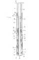
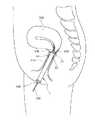
図1、図2および図3は、本発明の子宮挿入補助具の第1実施形態を示す模式的縦断面図、図4は、図1に示す子宮挿入補助具の使用方法を説明するための模式図である。なお、以下では、説明の都合上、図1〜図3の右側を「基端」、左側を「先端」と言う。 1, FIG. 2 and FIG. 3 are schematic longitudinal sectional views showing a first embodiment of the uterine insertion aid of the present invention, and FIG. 4 is a diagram for explaining a method of using the uterine insertion aid shown in FIG. It is a schematic diagram. In the following, for convenience of explanation, the right side of FIGS.
図1に示す子宮挿入補助具1は、子宮内へ薬剤等を投与したり、子宮内へ処置具を挿入したりする際に、その行為を補助するために膣内に挿入して用いられる補助具である。このような子宮挿入補助具1は、本体2と、第1固定手段3と、第2固定手段4と、第1固定手段3および第2固定手段4を操作する操作部5とを有している。 A uterine
以下、これら各要素について、順次詳細に説明する。
本体2は、筒状をなしている。また、本体2は、円筒状のベース21と、ベース21の先端部に設けられた軟質部22とで構成されている。Hereinafter, each of these elements will be described in detail.
The
ベース21は、軸方向に沿って外径がほぼ一定であり、直線的に形成されている。ただし、ベース21の形状は、これに限定されず、例えば、膣の形状に合わせて幾らか湾曲した形状であってもよい。 The
ベース21は、外筒211と、外筒211内に外筒211と同心的に設けられた内筒212とを有しており、内筒212によって形成された貫通孔213がベース21の基端と先端とに開口している。この貫通孔213は、後述するように、子宮内へ挿入する挿入管100等を通過させる貫通孔である。また、外筒211と内筒212との間には、空間S1が形成されており、この空間S1内に、子宮挿入補助具1を構成する各種部材が収容されている。 The
ベース21の外筒211には、複数の孔が形成されている。具体的には、外筒211の先端部には、ベース21の周方向に沿って4つの長孔61が形成されている。各長孔61は、ベース21の軸方向に延在し、ベース21の周方向に等間隔に形成されている。これら長孔61を介して後述する第1固定部31がベース21の外側へ突出したり、ベース21の内側へ退避したりする。 A plurality of holes are formed in the
さらに、外筒211の長孔61より基端側には、ベース21の周方向に沿って4つの長孔62が形成されている。各長孔62は、ベース21の軸方向に延在し、ベース21の周方向に等間隔に形成されている。これら長孔62を介して後述する第2固定部41がベース21の外側へ突出したり、ベース21の内側へ退避したりする。 Furthermore, four
さらに、外筒211の長孔62よりも基端側には、長孔63がベース21の軸方向に延在して形成されている。このような長孔63は、後述する係合部471を係合させるための孔である。 Further, a
さらに、外筒211の長孔63よりも基端側であって、ベース21の基端部には、長孔64がベース21の軸方向に延在して形成されている。このような長孔64は、後述する第1スイッチ36を案内するガイドとしての機能を果たす。また、長孔64は、その途中に途切れた部分を有しており、当該部分が第1スイッチ36と係合する係合部641を構成する。 Further, a
なお、外筒211の外周面には、目印が形成されていてもよい。この目印は、子宮挿入補助具1の膣内への挿入深さを判断するための目印として用いることができる。そのため、目印の構成や数は、特に限定されず、例えば、子宮挿入補助具1の先端側から等間隔ごとに複数の目印を形成してもよい。また、目印とともに子宮挿入補助具1の先端からの距離を示す数字を表示してもよい。なお、目印は、必要に応じて形成すればよく、省略してもよい。 In addition, a mark may be formed on the outer peripheral surface of the
ベース21の構成材料は、特に限定されず、例えば、ポリエチレン、ポリプロピレン、エチレン−酢酸ビニル共重合体等のポリオレフィン、ポリウレタン、ポリアミド、ポリエステル、ポリカーボネート、ポリブタジエン、ポリ塩化ビニル等の各種樹脂材料が挙げられる。 The constituent material of the
ベース21の先端部に設けられた軟質部22は、略半球状をなしている。また、軟質部22は、その先端部に円形の孔221が形成されている。この孔221は、ベース21が有する貫通孔213と同軸的に形成されている。また、軟質部22は、内側に空間S2を有しており、ベース21の先端部から空間S2に、後述する第2スイッチ46の先端部461が突出している。 The
軟質部22は、弾性を有しており、外力により容易に弾性変形し、外力が解除されれば速やかに元の形状に復帰する。 The
軟質部22の構成材料は、例えば、天然ゴム、イソプレンゴム、ブチルゴム、ブタジエンゴム、スチレン−ブタジエンゴム、ウレタンゴム、ニトリルゴム、アクリルゴム、フッ素ゴム、シリコーンゴムのような各種ゴム材料や、ウレタン系、ポリエステル系、ポリアミド系、オレフィン系、スチレン系等の各種熱可塑性エラストマー、あるいはそれらの混合物等の各種弾性材料が挙げられる。 The constituent material of the
以上、本体2について説明したが、本体2のサイズ、例えば、成人女性の平均的な膣の形状・大きさを考慮して決定すればよい。例えば、本体2の長さは、10cm〜20cm程度であるのが好ましく、外径は、2cm〜4cm程度であるのが好ましい。これにより、患者の個体差に影響を受け難い子宮挿入補助具1となる。 The
ベース21には、操作部5が設けられている。操作部5は、筒状をなし、その中央部に軸方向に延びる貫通孔51を有している。この貫通孔51は、ベース21の貫通孔213と連通している。 The
また、操作部5は、ベース21に対してその軸方向に摺動可能に設けられている。操作部5がベース21に対して摺動する際には、ベース21の外筒211および内筒212がガイドとして機能する。 The
操作部5の基端には、ベース21の外径よりも大きいフランジ52が形成されており、このフランジ52とベース21とが当接することにより、操作部5の先端方向への過度な移動が制限される。 A
また、操作部5には、第1スイッチ36が形成されている。第1スイッチ36は、第1固定手段3の一部を構成するものである。第1スイッチ36は、ベース21の長孔64からベース21の外側へ突出するツマミ361と、長孔64の係合部641と係合するツメ部362とを有している。 In addition, a
操作部5の構成材料は、特に限定されず、例えば、ベース21と同様の構成材料を用いることができる。 The constituent material of the
次いで、第1固定手段3について説明する。
第1固定手段3は、子宮挿入補助具1を膣内へ挿入した状態にて、子宮挿入補助具1の先端部(貫通孔213の先端側開口および軟質部22の孔221)を子宮口に対して位置決めする機能を有している。Next, the first fixing means 3 will be described.
In the state where the uterine
第1固定手段3は、4つの第1固定部31と、各第1固定部31の形状を切り替える第1切替手段35とを有している。また、第1切替手段35は、第1スイッチ36と、第1接続部材37とを有している。 The first fixing means 3 includes four
各第1固定部31は、弾性を有する平板状(帯状)の長尺部材を一方向へ湾曲させた状態で形状付けしたものである。これにより、各第1固定部31の構成が簡単となる。なお、各第1固定部31は、例えば、線状のワイヤ等により構成されていてもよい。 Each first fixing
各第1固定部31は、外力が加わっていない自然状態において湾曲しており、引っ張り応力が加わると直線状に変形する。また、前記引っ張り応力が解除されると速やかに元の形状に復帰する。 Each first fixing
このような各第1固定部31は、自然状態にて、ベース21に形成された長孔61からベース21の外側へベース21の径方向に向けて突出している。すなわち、4つの第1固定部31は、ベース21の周方向に沿って等間隔に設けられている。これにより、第1固定部31によって子宮口周辺(子宮膣部や、膣円蓋(前膣円蓋、後膣円蓋)等の子宮膣部近傍の膣壁)を子宮口の周囲で均一に捉えることができ、子宮挿入補助具1の先端部を子宮口に対して、より正確かつ確実に、位置決めすることができる。 Each such
ここで、各第1固定部31の自然状態における最大突出高さH1aは、特に限定されないが、1cm〜5cm程度であるのが好ましく、2cm〜3cm程度であるのがより好ましい。このような数値範囲とすることで、各第1固定部31の高さが適当となり、後述するように、第1固定部31が子宮口周辺を確実に捉えることができ、子宮挿入補助具1の先端部を子宮口に対してより正確かつ確実に位置決めすることができる。さらに、第1固定部31が突出し過ぎて、比較的強い力で子宮口周辺に当接してしまうのを効果的に防止でき、子宮膣部や膣(膣壁)への負担を低減することができる。 Here, the maximum protrusion height H1a in the natural state of each first fixing
また、各第1固定部31は、自然状態において、本体2の先端よりも先端側へ突出しているのが好ましい。具体的には、各第1固定部31の自然状態における最大突出長さH1bは、0.5cm〜4cm程度であるのが好ましく、2cm〜3cm程度であるのがより好ましい。図4に示すように、子宮膣部は、子宮口付近が最も盛り上がっており、周囲に向かうに連れて奥まっていく。そのため、第1固定部31を本体2よりも先端側へ突出させることにより、第1固定部31によって、より確実に、子宮口周辺を捉えることができ、子宮挿入補助具1の先端部を子宮口に対してより正確かつ確実に位置決めすることができる。 Moreover, it is preferable that each 1st fixing | fixed
このような各第1固定部31は、形状記憶材料で構成されており、前記形状記憶材料としては、例えば、Ni−Ti合金等の金属材料等が挙げられる。 Each of the
なお、各第1固定部31には、その摩擦(摺動抵抗)を低減し、摺動性を向上させるための表面処理が施されていてもよい。これにより、第1固定部31との接触による子宮膣部や膣壁への負担を低減することができる。 Each first fixing
このような目的のためには、各第1固定部31の表面に、摩擦を低減し得る材料で構成された図示しない被覆層を形成するのが好ましい。このような摩擦を低減し得る材料としては、例えば、ポリエチレン、ポリプロピレン等のポリオレフィン、ポリ塩化ビニル、ポリエステル(PET、PBT等)、ポリアミド、ポリイミド、ポリウレタン、ポリスチレン、ポリカーボネート、シリコーン樹脂、フッ素系樹脂(PTFE、ETFE等)、またはこれらの複合材料が挙げられる。 For this purpose, it is preferable to form a coating layer (not shown) made of a material capable of reducing friction on the surface of each first fixing
このような各第1固定部31は、先端側の端部がベース21に固定されており、基端側の端部が第1接続部材37に固定されている。 Each of the
第1接続部材37は、ベース21の空間S1内に設けられている。第1接続部材37は、環状をなしており、ベース21に対して、その軸方向に摺動可能に設けられている。第1接続部材37がベース21に対して摺動する際には、ベース21の外筒211および内筒212がガイドとして機能する。 The
第1接続部材37の構成材料は、特に限定されず、例えば、ベース21と同様の構成材料を用いることができる。 The constituent material of the
第1接続部材37は、少なくとも一本の紐38によって操作部5に接続されている。本実施形態では、紐38は、後述する第2接続部材47に形成された図示しない貫通孔を通って第1接続部材37と操作部5とを連結している。なお、各第1固定部31が自然状態のとき、紐38は、緊張していても緩んでいてもよいが、緩んでいるのが好ましい。これにより、各第1固定部31が自然状態のときには、紐38に引っ張り応力が加わらないため、子宮挿入補助具1の耐久性および信頼性を高めることができる。 The
第1スイッチ36は、各第1固定部31がベース21の内側へ退避した状態を維持・解除する機能を有している。なお、第1スイッチ36の構成については、前述した通りであるため、ここでの説明は省略する。このような第1スイッチ36を有することにより、子宮挿入補助具1の操作性が向上する。 The
このような第1固定手段3は、次のように作動する。
例えば、第1固定部31がベース21から突出した状態にて、フランジ52を把持して操作部5を本体2に対して基端側へ移動させると、紐38が緊張し、それにより、第1接続部材37が操作部5と共に基端側へ移動する。そして、この第1接続部材37の移動によって各第1固定部31に引っ張り応力が加わり、各第1固定部31は、徐々に直線状に変形してゆく。操作部5を基端側へさらに移動させると、図2に示すように、ツメ部362が係合部641に係合し、操作部5および第1接続部材37が本体2に固定される。ツメ部362が係合部641に係合した状態では、各第1固定部31は、ほぼ直線状となり、ベース21の内側へ退避している。Such first fixing means 3 operates as follows.
For example, when the first fixing
反対に、本体2に対する第1接続部材37の固定を解除するには、ツマミ361をベース21内へ向けて押し込めばよい。これにより、ツメ部362と係合部641との係合状態が解除され、各第1固定部31が復元力によって自然状態へ復帰するように変形し、図3に示すように、各第1固定部31が対応する長孔61からベース21の外側へ突出するとともに、第1接続部材37および操作部5が先端側へ移動する。 On the contrary, in order to release the fixing of the first connecting
このような第1固定手段3によれば、簡単な構成で、各第1固定部31をベース21から突出させたり、ベース21内へ退避させたりすることができるため、子宮挿入補助具1の操作性が向上する。 According to such first fixing means 3, each first fixing
特に、本実施形態では、第1スイッチ36を有しており、各第1固定部31がベース21内へ退避した状態を維持したり、解除したりすることができるため、子宮挿入補助具1の操作性が向上する。さらに、第1スイッチ36がベース21の基端側に位置しているため、子宮挿入補助具1を膣内の所定位置まで挿入した状態でも第1スイッチ36が膣外にあり、その操作が容易となる。これにより、子宮挿入補助具1の操作性がさらに向上する。 In particular, in the present embodiment, the
次いで、第2固定手段4について説明する。
第2固定手段4は、子宮挿入補助具1を膣内に固定する機能を有している。このような第2固定手段4は、4つの第2固定部41と、各第2固定部41の形状を切り替える第2切替手段45とを有している。また、第2切替手段45は、第2スイッチ46と、第2接続部材47とを有している。Next, the second fixing means 4 will be described.
The second fixing means 4 has a function of fixing the uterine
各第2固定部41は、平板状の長尺部材を一方向へ湾曲させた状態で形状付けしたものである。すなわち、各第2固定部41は、外力が加わっていない自然状態において湾曲しており、引っ張り応力が加わると直線状に変形する。また、前記引っ張り応力が解除されると速やかに元の形状に復帰する。 Each of the
このような各第2固定部41の構成は、第1固定部31と同様であるため、その説明を省略する。 Since the configuration of each of the
このような各第2固定部41は、自然状態にて、ベース21に形成された長孔62からベース21の外側へベース21の径方向に向けて突出している。すなわち、4つの第2固定部41は、ベース21の周方向に沿って等間隔に設けられている。これにより、第2固定部41によって膣壁を均一に捉えることができ、子宮挿入補助具1を膣に対してより正確かつ確実に固定することができる。 Each such
ここで、各第2固定部41の自然状態における最大突出高さH2は、特に限定されないが、1cm〜5cm程度であるのが好ましく、2cm〜4cm程度であるのがより好ましい。また、最大突出高さH2は、前述した第1固定部31の最大突出高さH1よりも高いことが好ましい。これにより、各第2固定部41をより確実に膣内壁に当接することができ、より確実に、子宮挿入補助具1を膣に対して固定することができる。さらに、各第2固定部41が突出し過ぎて、比較的強い力で膣壁に当接してしまうのを効果的に防止でき、膣への負担を低減することができる。 Here, the maximum protrusion height H2 in the natural state of each second fixing
このような各第2固定部41は、その先端側の端部がベース21に固定されており、基端側の端部が第2接続部材47に固定されている。 Each of the
第2接続部材47は、ベース21の空間S1内に設けられている。第2接続部材47は、環状をなしており、ベース21に対して、その軸方向に摺動可能に設けられている。第2接続部材47がベース21に対して摺動する際には、ベース21の外筒211および内筒212がガイドとして機能する。 The
また、第2接続部材47は、ベース21に形成された長孔63に係合する係合部471を有している。係合部471は、その根元部471bが弾性を有しており、根元部471bが弾性変形することにより先端部471aがベース21の径方向に変位する。 The second connecting
また、先端部471aは、蒲鉾状(球面体の上部を平行に切断した形状)をなしており、外筒211側の面が外筒211の軸方向に湾曲した曲面で構成されている。係合部471をこのような形状とすることで、後述するように、係合部471と長孔63との係合および係合解除をより確実かつスムーズに行うことができる。 The
このような第2接続部材47の構成材料は、特に限定されず、例えば、ベース21と同様の構成材料を用いることができる。 The constituent material of the
第2接続部材47は、少なくとも一本の紐48によって操作部5に接続されている。なお、各第2固定部41が自然状態のとき、紐48は、緊張していても緩んでいてもよいが、緩んでいるのが好ましい。これにより、各第2固定部41が自然状態のときは、紐48に引っ張り応力が加わらないため、子宮挿入補助具1の耐久性および信頼性を高めることができる。 The
第2スイッチ46は、各第2固定部41がベース21の内側へ退避した状態を維持・解除する機能を有している。このような第2スイッチ46を有することにより、子宮挿入補助具1の操作性が向上する。 The
第2スイッチ46は、棒状の部材であり、先端部461を除いてベース21内に設けられている。第2スイッチ46の先端部461は、ベース21の先端から突出しており、軟質部22の内側、すなわち空間S2内に位置している。 The
また、第2スイッチ46は、第1接続部材37および第2接続部材47に形成された貫通孔に挿通されており、ベース21に対してその軸方向に変位可能である。第2スイッチ46が変位する際には、第1接続部材37および第2接続部材47に形成された前記貫通孔がガイドとして機能する。 The
また、第2スイッチ46の先端側には、空間S1内に位置するフランジ461aと、空間S2内に位置するフランジ461bとが形成されている。さらに、フランジ461bとベース21との間には、バネ部材(付勢部材)49が設けられており、このバネ部材49によって、第2スイッチ46が先端側へ付勢されている。 In addition, a
第2スイッチ46の基端部462は、第2スイッチ46がバネ部材49に付勢されて最も先端側に位置している状態にて、ベース21に形成された長孔63と対向するように位置している。また、基端部462は、先端側へ向けて厚さが漸減した部分を有し、これにより、ベース21の軸方向に対して傾斜した面462aが形成されている。この面462aは、第2接続部材47の係合部471をベース21の外側に向けて付勢する機能を有している。 The
このような第2スイッチ46の構成材料は、特に限定されず、例えば、ベース21と同様の構成材料を用いることができる。 The constituent material of the
このような、第2固定手段4は、次のように作動する。
例えば、第2固定部41がベース21から突出した状態にて、フランジ52を把持して操作部5を本体2に対して基端側へ移動させると、紐48が緊張し、それにより、第2接続部材47が操作部5と共に基端側へ移動する。そして、この第2接続部材47の移動によって各第2固定部41に引っ張り応力が加わり、各第2固定部41が徐々に直線状に変形してゆく。操作部5を基端側へさらに移動させると、第2接続部材47が有する係合部471が第2スイッチ46の面462aに接触し、面462aに沿いながらベース21の外側へ向けて変位し、長孔63と係合する。これにより、第2接続部材47が本体2に固定される。第2スイッチ46は、バネ部材49によって先端側へ付勢されているため、係合部471との接触によっては基端側へ実質的に変位せず、係合部471と長孔63とを確実に係合させることができる。Such second fixing means 4 operates as follows.
For example, when the second fixing
係合部471が長孔63に係合した状態では、各第2固定部41は、ほぼ直線状となり、ベース21の内側へ退避している。 In a state where the engaging
反対に、本体2に対する第2接続部材47の固定を解除するには、本体2に対する第1接続部材37の固定を解除し、紐48を緩めた状態とした後、第2スイッチ46を基端側へ押し込めばよい。なお、第2スイッチ46の押し込みは、後述するように、膣内に挿入された子宮挿入補助具1をさらに押し込み、軟質部22を子宮膣部(子宮口周辺)に押し当てることにより変形させることで実行する。 On the other hand, to release the second connecting
これにより、第2スイッチ46の基端部462が基端側に移動し、係合部471がベース21の内側へ向けて変位可能となる。この状態では、第2接続部材47は、第2固定部41の復元力により先端側へ付勢されているため、その復元力によって係合部471がベース21内へ向けて変位し、係合部471と長孔63との係合状態が解除される。そして、各第2固定部41が自然状態に復帰し、それに伴って第2接続部材47が先端側へ移動する。 As a result, the
特に、本実施形態の係合部471は、蒲鉾状をなしているため、係合部471が長孔63に引っ掛かる等、各第2固定部41の復元力に対抗する力の発生を抑制することができる。そのため、係合部471と長孔63との係合状態を円滑かつ確実に解除することができる。 In particular, since the engaging
このような第2固定手段4によれば、簡単な構成で、各第2固定部41をベース21から突出させたり、ベース21内へ退避させたりすることができるため、子宮挿入補助具1の操作性が向上する。 According to the second fixing means 4 as described above, each second fixing
特に、本実施形態では、第2スイッチ46を有しており、各第2固定部41がベース21内へ退避した状態を維持したり、解除したりすることができるため、子宮挿入補助具1の操作性が向上する。さらに、子宮挿入補助具1を子宮膣部に押し当て、軟質部22を変形させることにより第2スイッチ46を操作することができるため、第2スイッチ46の操作を盲目的であってもより確実かつ簡単に行うことができる。 In particular, in the present embodiment, the
以上、子宮挿入補助具1の構成について詳細に説明した。
このような子宮挿入補助具1は、例えば、次のようにして使用することができる。なお、以下では、説明の便宜上、各第1固定部31および各第2固定部41がベース21から突出している状態を「第1状態」と言い、各第1固定部31および各第2固定部41がベース21内へ退避している状態を「第2状態」と言う。また、下記の使用方法は、一例であり、これに限定されない。The configuration of the
Such a
まず、図1に示すような第1状態の子宮挿入補助具1を用意する。次いで、フランジ52を把持して操作部5を本体2に対して基端側へ移動させると、紐38、48がそれぞれ緊張し、それにより第1接続部材37および第2接続部材47が操作部5と共に基端側へ移動する。操作部5の基端側への移動を続けると、図2に示すように、第2接続部材47の係合部471が長孔63と係合するとともに、第1スイッチ36が長孔64の係合部641と係合する。これにより、第1接続部材37および第2接続部材47がベース21に対して固定される。この状態では、各第1固定部31および各第2固定部41が直線状に変形し、ベース21内に退避した第2状態となる。 First, a uterine
ここで、係合部471と長孔63との係合と、第1スイッチ36と係合部641との係合は、同時に起こってもよく、時間的にずれて起こってもよいが、時間的にずれて起こるのが好ましい。具体的には、操作部5を基端側へ移動してゆく過程において、まず係合部471が長孔63に係合し、さらに操作部5を基端側へ移動させることにより第1スイッチ36が係合部641に係合するのが好ましい。 Here, the engagement between the
係合部471が長孔63に係合する時、第1スイッチ36が係合部641に係合する時には、それぞれ、音や振動が発生する。この音や振動により、患者は、前記係合が正常に行われたことを確認することができるが、この音や振動が、時間的にずれて二度発生することにより、係合部471と長孔63との係合、第1スイッチ36と係合部641との係合が共に正常に行われたことを簡単に確認することができる。そのため、患者に安心感を与えることができる。 When the engaging
次いで、図4に示すように、第2状態とした子宮挿入補助具1をその先端側から膣310に挿入し、子宮挿入補助具1の先端部を子宮膣部320に到達させる。このように、各第1固定部31および各第2固定部41がベース21内へ退避した状態とすることにより、膣310内への子宮挿入補助具1の挿入をスムーズに行うことができる。 Next, as shown in FIG. 4, the uterine
患者は、子宮挿入補助具1の先端部が子宮膣部320に接触した感覚を得た後、第1スイッチ36を押し込んで第1スイッチ36と係合部641との係合を解除する。これにより、各第1固定部31に加わっていた引っ張り応力が解除されるため、第1固定部31が第1状態へ復帰しようと変形する。この変形によって、各第1固定部31がベース21の外側へ突出し、子宮口周辺(子宮膣部320または膣310の内壁)に当接する。これにより、子宮口330に対して子宮挿入補助具1の先端部の位置決めが行われ、軟質部22に形成された孔221と子宮口330とが対向する。 After obtaining the sensation that the distal end portion of the uterine
ここで、各第1固定部31は、患者の子宮膣部320や膣310の形状に合わせて独立して変形するため、子宮挿入補助具1によれば、患者の子宮膣部320や膣310の形状に影響されずに、より正確に、孔221と子宮口とが対向するように位置決めを行うことができる。また、4つの第1固定部31によって、子宮口330の周囲4箇所で位置決めを行うため、子宮口330に対する子宮挿入補助具1の位置決めをより正確に行うことができ、位置決めした後もその状態をより確実に維持することができる。 Here, since each 1st fixing | fixed
なお、この状態では、子宮挿入補助具1は、図3に示すような状態となっており、第2固定部41は、ベース21内に退避したままである。 In this state, the
このように、4つの第1固定部31による子宮挿入補助具1の位置決めを行った後、患者は、子宮挿入補助具1をさらに膣内へ押し込む。子宮挿入補助具1を押し込むと、子宮膣部320と接触している軟質部22が潰されて、第2スイッチ46がベース21内へ押し込まれる。第2スイッチ46が押し込まれると、係合部471と長孔63との係合が解除され、各第2固定部41が第1状態へ復帰しようと変形する。この変形によって、各第2固定部41がベース21の外側へ突出し、膣310の内壁に当接する。これにより、子宮挿入補助具1が膣310に固定される。 Thus, after positioning the
ここで、各第2固定部41は、患者の膣310の形状に合わせて独立して変形するため、患者の膣310の形状に影響されずに、より確実に、子宮挿入補助具1を固定することができる。また、ベース21の周囲に均等に配置された4つの第2固定部41によって膣310に固定するため、子宮挿入補助具1の膣310への固定をバランス良く行うことができ、固定した後もその状態をより確実に維持することができる。 Here, since each 2nd fixing | fixed
また、各第2固定部41は、第1固定部31に対してベース21の軸方向へ離間しており、ベース21の軸方向の中央部寄りに設けられているため、子宮挿入補助具1の膣310への固定をよりバランス良く行うことができる。 In addition, each second fixing
以上のような操作により、図4に示す状態となり、子宮挿入補助具1の膣310への挿入が完了する。 By the above operation, the state shown in FIG. 4 is obtained, and the insertion of the uterine
前述したように、子宮挿入補助具1では、第1固定手段3によって子宮口330に対する子宮挿入補助具1の先端部の位置決めを行った後に、第2固定手段4によって子宮挿入補助具1を膣310に固定するように操作する。このような手順に従うことにより、子宮挿入補助具1の操作性がより向上する。 As described above, in the uterine
すなわち、第2固定手段4によって膣310に固定されておらず膣内での移動の自由度が比較的高い状態で、第1固定手段3によって子宮口330に対する子宮挿入補助具1の先端部の位置決めを行うことにより、当該位置決めをより正確に行うことができる。そして、この位置決めを行った後に、第2固定手段4によって子宮挿入補助具1を膣310に固定すれば、子宮口330に対する子宮挿入補助具1の先端の位置決めがされたままの状態で子宮挿入補助具1を膣310に固定することができる。このように、前記手順に従えば、子宮挿入補助具1の操作性がより向上する。 That is, in the state where the second fixing means 4 is not fixed to the
特に、本実施形態の子宮挿入補助具1では、第1固定手段3による位置決めを行い、紐48を緩めた状態とした後でなければ、第2固定手段4による固定が実行できない構成となっている。そのため、誤った使用方法や誤作動を確実に防止することができ、装置の安全性が向上する。 In particular, the uterine
また、子宮挿入補助具1では、各第1固定部31および各第2固定部41が自然状態で湾曲しベース21から突出している。これにより、子宮挿入補助具1の操作性がより向上する。すなわち、第1スイッチ36を解除するだけで各第1固定部31の復元力により自動的に子宮口330に対する位置決めが行われ、さらに係合部471の係合を解除するだけで各第2固定部41の復元力により自動的に膣310への固定が行われるため、簡単な操作のみで子宮挿入補助具1を使用することができる。 Further, in the uterine
次いで、図4に示すように、患者は、子宮挿入補助具1の基端側から貫通孔213内に挿入管100を挿入し、挿入管100の先端部を貫通孔213の先端側開口および軟質部22の孔221から突出させて、子宮口330を介して子宮340内へ挿入する。このように、子宮挿入補助具1を用いて挿入管100の子宮340内への挿入を行うことにより、盲目的であっても、挿入管100の子宮340内への挿入を患者自ら簡単に行うことができる。 Next, as shown in FIG. 4, the patient inserts the
挿入管100は、硬質であっても軟質であってもよいが、硬質であるのが好ましい。これにより、子宮340内への挿入がより簡単となる。また、挿入管100の基端部は、貫通孔213の内径よりも大きくなっており、挿入管100の子宮340内への過度な挿入が防止される。これにより、挿入管100の子宮340内への挿入を安全に行うことができる。 The
挿入管100を子宮340内へ挿入し終えたら、さらに、挿入管100内に薬剤投与チューブ200を挿入し、薬剤投与チューブ200の先端を挿入管100から突出させて、子宮340内の所定位置に位置させる。次いで、患者は、薬剤投与チューブ200を介して所定の薬剤を子宮340内に投与する。 When the
子宮内に投与する薬剤の種類は、特に限定されず、例えば、鎮痛剤、黄体ホルモン・Gn−Rha等のホルモン剤である子宮疾患に対する薬、子宮洗浄用の洗浄液(精製水、生理食塩水など)、避妊のための殺精子剤(例えば、メンフェゴール配合の薬剤)、子宮体癌、堕胎のための抗がん剤、不妊治療における人工授精のための精子や体外受精のための胚、避妊または子宮疾患治療のために子宮内に留置する子宮内避妊器具(IUD)等が挙げられる。 The type of drug to be administered into the uterus is not particularly limited. For example, analgesics, drugs for uterine diseases such as luteinizing hormones / Gn-Rha, uterine irrigation washing liquid (purified water, physiological saline, etc.) ), Spermicides for contraception (for example, drugs containing memphegol), endometrial cancer, anticancer agents for abortion, sperm for artificial insemination in infertility treatment or embryos for in vitro fertilization, contraception or Examples thereof include an intrauterine contraceptive device (IUD) placed in the uterus for the treatment of uterine diseases.
また、薬剤の状態も特に限定されず、例えば、液状、ゲル状、ムース状、固形状であってもよい。 Further, the state of the drug is not particularly limited, and may be, for example, liquid, gel, mousse, or solid.
特に、洗浄液などは、子宮340内へ供給した後、子宮340内から吸引し、循環させる必要がある。子宮挿入補助具1では、第1固定部31が帯状の形状をなし、互いに離間して設けられているため、第1固定部31によって子宮340口が塞がれていない。すなわち子宮挿入補助具1は、子宮340内を密閉していないため、前述したような洗浄液の循環をスムーズに行うことができる。 In particular, the cleaning liquid or the like needs to be sucked from the
また、子宮340内に処置具を挿入する場合は、挿入管100を子宮340内へ挿入した後、挿入管100を介して子宮340内へ処置具を挿入すればよい。挿入する処置具としては、特に限定されず、例えば、子宮疾患に対する治療デバイスである子宮粘膜下筋腫、子宮内膜ポリープに対するレゼクトスコープ・レーザー、子宮内膜掻爬用キュレット、子宮内膜吸引チューブや、子宮体癌検診用細胞摂取器具、子宮内観察用のための内視鏡(卵管鏡、子宮鏡等)が挙げられる。 In addition, when a treatment tool is inserted into the
なお、処置具の挿入を目的とする場合は、子宮挿入補助具1の膣310内への挿入および子宮340内への処置具の挿入については、熟練した医師によって行われるのが好ましい。 For the purpose of insertion of the treatment tool, the insertion of the uterine
<第2実施形態>
次いで、本発明の子宮挿入補助具の第2実施形態を説明する。Second Embodiment
Next, a second embodiment of the uterine insertion aid of the present invention will be described.
図5は、本発明の子宮挿入補助具の第2実施形態を示す模式的平面図、図6は、図5に示す子宮挿入補助具の模式的縦断面図であり、図7は、図6を子宮挿入補助具の軸まわりに45°回転させた模式的断面図である。なお、以下では、説明の都合上、図5〜図7の右側を「基端」、左側を「先端」と言う。また、図5では、説明の便宜上、本体以外の部位の図示を省略している。また、第1固定手段を説明するための図である図6と、第2固定手段を説明するための図である図7とでは、説明の便宜上、例えば、操作部材等の子宮挿入補助具を構成する各部の形状、大きさ、配置(他の部材との位置関係)等が若干異なっている。 FIG. 5 is a schematic plan view showing a second embodiment of the uterine insertion aid of the present invention, FIG. 6 is a schematic longitudinal sectional view of the uterine insertion aid shown in FIG. 5, and FIG. It is typical sectional drawing which rotated 45 degrees around the axis | shaft of the uterine insertion assistance tool. Hereinafter, for convenience of explanation, the right side of FIGS. 5 to 7 is referred to as a “base end”, and the left side is referred to as a “tip”. Further, in FIG. 5, illustration of parts other than the main body is omitted for convenience of explanation. In FIG. 6 for explaining the first fixing means and FIG. 7 for explaining the second fixing means, for convenience of explanation, for example, a uterine insertion assisting tool such as an operation member is used. The shape, size, arrangement (positional relationship with other members), and the like of each part constituting are slightly different.
以下、本実施形態の子宮挿入補助具について説明するが、前記第1実施形態の子宮挿入補助具との相違点を中心に説明し、同様の事項については、その説明を省略する。 Hereinafter, although the uterine insertion assistance tool of this embodiment is demonstrated, it demonstrates centering on difference with the uterine insertion assistance tool of the said 1st Embodiment, and the description is abbreviate | omitted about the same matter.
本実施形態の子宮挿入補助具では、主に第1固定手段および第2固定手段の構成が異なる以外は、前記第1実施形態の子宮挿入補助具と同様である。 The uterine insertion assisting tool of the present embodiment is the same as the uterine insertion assisting tool of the first embodiment except that the configurations of the first fixing means and the second fixing means are mainly different.
図5に示すように、4つの長孔61と4つの長孔62は、ベース21の周方向に略45°ずれるようにしてベース21に形成されている。このように長孔61、62をベース21の周方向にずらすことにより、第1固定手段3および第2固定手段4の配置が簡単となる。 As shown in FIG. 5, the four
次いで、図6に基づいて、第1固定手段3について説明する。
第1固定手段3は、4つの第1固定部31Aと、各第1固定部31Aの形状を切り替える第1切替手段とを有している。また、第1切替手段は、第1スイッチ36と、第1接続部材37とを有している。Next, the first fixing means 3 will be described with reference to FIG.
The first fixing means 3 includes four
各第1固定部31Aは、湾曲変形可能な平板状の長尺部材で構成されている。なお、第1固定部31Aは、弾性を有していても有していなくてもよい。このような第1固定部31Aは、後述するように、第1接続部材37の変位に応じて変形することにより、長孔61からベース21の外側へ突出したり、長孔61からベース21の内側に退避したりする。 Each first fixing
各第1固定部31Aの構成材料としては、例えば、Ni−Ti合金等の金属材料、天然ゴム、イソプレンゴム、ブチルゴム、ブタジエンゴム、スチレン−ブタジエンゴム、ウレタンゴム、ニトリルゴム、アクリルゴム、フッ素ゴム、シリコーンゴムのような各種ゴム材料等が挙げられる。 As a constituent material of each first fixing
このような各第1固定部31Aは、先端側の端部がベース21に固定されており、基端側の端部が第1接続部材37に固定されている。第1接続部材37は、少なくとも一本の連結棒38Aによって操作部5に接続されている。 Each of the
連結棒38Aは、ベース21の外筒211から内側へ突出する突起211aに形成された貫通孔、後述する先端側第2接続部材47aに形成された貫通孔および後述する基端側第2接続部材47bに形成された貫通孔を通って第1接続部材37と操作部5とを連結している。 The connecting
また、第1接続部材37と突起211aとの間には、連結棒38Aを軸としてバネ部材39Aが設けられている。このバネ部材39Aは、第1接続部材37を先端側へ付勢しており、バネ部材39Aの付勢力に対向して第1接続部材37を基端側へ移動させることにより、各第1固定部31Aをベース21内に退避させ、バネ部材39Aの付勢力によって第1接続部材37を先端側へ移動させることにより各第1固定部31Aをベース21から突出させることができる。 A
このような第1固定手段3は、次のように作動する。
例えば、第1固定部31Aがベース21から突出した状態にて、フランジ52を把持して操作部5を本体2に対して基端側へ移動させると、連結棒38Aで操作部5と連結している第1接続部材37が操作部5と共に基端側へ移動する。この第1接続部材37の移動によって各第1固定部31Aに引っ張り応力が加わり、各第1固定部31Aは、徐々に直線状に変形してゆく。操作部5を基端側へさらに移動させると、ツメ部362が係合部641に係合し、操作部5および第1接続部材37が本体2に固定される。ツメ部362が係合部641に係合した状態では、各第1固定部31Aは、ほぼ直線状となり、ベース21の内側へ退避している。また、バネ部材39Aは、第1接続部材37と突起211aとに狭持されることにより収縮状態となっている。Such first fixing means 3 operates as follows.
For example, when the
反対に、本体2に対する第1接続部材37の固定を解除するには、ツマミ361をベース21内へ向けて押し込めばよい。これにより、ツメ部362と係合部641との係合状態が解除され、本体2に対する第1接続部材37の固定が解除される。すると、バネ部材39Aの付勢力によって、第1接続部材37が先端側に移動する。その結果、図6に示すように、各第1固定部31Aが湾曲変形しながら長孔61からベース21の外側へ突出する。 On the contrary, in order to release the fixing of the first connecting
このような第1固定手段3によれば、簡単な構成で、各第1固定部31Aをベース21から突出させたり、ベース21内へ退避させたりすることができるため、子宮挿入補助具1の操作性が向上する。 According to such first fixing means 3, each first fixing
次いで、第2固定手段4について説明する。
第2固定手段4は、4つの第2固定部41Aと、各第2固定部41Aの形状を切り替える第2切替手段とを有している。また、第2切替手段は、第2スイッチ46と、先端側第2接続部材47aと、基端側第2接続部材47bとを有している。Next, the second fixing means 4 will be described.
The second fixing means 4 includes four
各第2固定部41Aは、湾曲変形可能な平板状の長尺部材で構成されている。なお、第2固定部41Aは、第1固定部31Aと同様に弾性を有していても有していなくてもよい。このような第2固定部41Aは、後述するように、先端側第2接続部材47aの変位に応じて変形することにより、長孔62からベース21の外側へ突出したり、長孔62からベース21の内側に退避したりする。 Each of the
第2固定部41Aの構成材料は、第1固定部31Aと同様のものを用いることができる。 As the constituent material of the
このような各第2固定部41は、その先端側の端部がベース21に固定されており、基端側の端部が先端側第2接続部材47aに固定されている。 Each of the
先端側第2接続部材47aは、ベース21の空間S1内に設けられている。先端側第2接続部材47aは、環状をなしており、ベース21に対して、その軸方向に摺動可能に設けられている。先端側第2接続部材47aがベース21に対して摺動する際には、ベース21の外筒211および内筒212がガイドとして機能する。 The distal end side
先端側第2接続部材47aの構成材料は、特に限定されず、例えば、ベース21と同様の構成材料を用いることができる。 The constituent material of the distal end side
先端側第2接続部材47aの基端側には、基端側第2接続部材47bが配置されている。この基端側第2接続部材47bは、前述の第1実施形態で説明した第2接続部材47と同様の構成であるため、その説明を省略する。 A proximal-side
先端側第2接続部材47aは、少なくとも一本の連結棒48Aによって基端側第2接続部材47bと連結されており、基端側第2接続部材47bは、少なくとも一本の紐48によって操作部5に接続されている。 The distal-end-side second connecting
連結棒48Aは、ベース21の外筒211から内側へ突出する突起211bに形成された貫通孔を通って先端側第2接続部材47aと基端側第2接続部材47bとを連結している。 The connecting
また、先端側第2接続部材47aと突起211bとの間には、連結棒48Aを軸としてバネ部材49Aが設けられている。このバネ部材49Aは、先端側第2接続部材47aを先端側へ付勢している。そのため、バネ部材49Aの付勢力に対向して先端側第2接続部材47aを基端側へ移動させることにより、各第2固定部41Aをベース21内に退避させ、バネ部材49Aの付勢力によって先端側第2接続部材47aを先端側へ移動させることにより、各第2固定部41Aをベース21から突出させることができる。 In addition, a
このような、第2固定手段4は、次のように作動する。
例えば、第2固定部41Aがベース21から突出した状態にて、フランジ52を把持して操作部5を本体2に対して基端側へ移動させると、紐48が緊張し、それにより、先端側第2接続部材47aおよび基端側第2接続部材47bが操作部5と共に基端側へ移動する。この先端側第2接続部材47aの移動によって各第2固定部41Aに引っ張り応力が加わり、各第2固定部41Aが徐々に直線状に変形してゆく。操作部5を基端側へさらに移動させると、基端側第2接続部材47bが有する係合部471が第2スイッチ46の面462aに接触し、面462aに沿いながらベース21の外側へ向けて変位し、長孔63と係合する。これにより、第2接続部材47a、47bが本体2に固定される。係合部471が長孔63に係合した状態では、各第2固定部41は、ほぼ直線状となり、ベース21の内側へ退避している。また、バネ部材49Aは、先端側第2接続部材47aと突起211bとに狭持されることにより収縮状態となっている。Such second fixing means 4 operates as follows.
For example, when the
反対に、本体2に対する第2接続部材47a、47bの固定を解除するには、本体2に対する第1接続部材37の固定を解除し、紐48を緩めた状態とした後、第2スイッチ46を基端側へ押し込めばよい。これにより、第2スイッチ46の基端部462が基端側に移動し、係合部471がベース21の内側へ向けて変位可能となる。この状態では、第2接続部材47a、47bは、バネ部材49Aの付勢力により先端側へ付勢されているため、その付勢力によって係合部471がベース21内へ向けて変位し、係合部471と長孔63との係合状態が解除される。すると、バネ部材49Aの付勢力によって、第2接続部材47a、47bが先端側に移動する。その結果、図7に示すように、各第2固定部41Aが湾曲変形しながら長孔62からベース21の外側へ突出する。 On the contrary, in order to release the fixing of the
このような第2固定手段4によれば、簡単な構成で、各第2固定部41Aをベース21から突出させたり、ベース21内へ退避させたりすることができるため、子宮挿入補助具1の操作性が向上する。 According to such second fixing means 4, each second fixing
以上、子宮挿入補助具1の構成について詳細に説明した。なお、前述したように、本実施形態では、長孔61、62をベース21の周方向に略45°ずらして形成しているため、連結棒38A、48Aを、他の部材と干渉することなく、簡単に設置できるようになっている。 The configuration of the
本実施形態の子宮挿入補助具1の使用方法は、前述した第1実施形態と同様であるため、その説明を省略する。 Since the usage method of the uterine
以上、本発明の子宮挿入補助具を図示の実施形態について説明したが、本発明は、これに限定されるものではなく、子宮挿入補助具を構成する各部は、同様の機能を発揮し得る任意の構成のものと置換することができる。また、任意の構成物が付加されていてもよい。 As mentioned above, although the illustrated embodiment of the uterine insertion assisting device has been described, the present invention is not limited to this, and each part constituting the uterine insertion assisting device is an arbitrary one that can exhibit the same function. It can be replaced with the configuration of Moreover, arbitrary components may be added.
また、前述した子宮挿入補助具では、4つの第1固定部を有しているが、第1固定部の数は、2つ以上であれば、特に限定されない。ただし、第1固定部の数としては、ベース21への設置の問題や子宮口に対する位置決めの安定性の観点から、3つ〜8つ程度であるのが好ましい。第2固定具の数についても、これと同様である。 Moreover, although the uterine insertion assisting tool described above has four first fixing portions, the number of the first fixing portions is not particularly limited as long as it is two or more. However, the number of the first fixing portions is preferably about 3 to 8 from the viewpoint of installation on the
また、前述した子宮挿入補助具では、第1固定部および第2固定部が共に自然状態で湾曲した形状をなし、引っ張り応力を与えることで直線状に変形するよう構成されているが、第1固定部および第2固定部の構成は、これに限定されず、自然状態で直線状をなしており、収縮応力を与えることで湾曲変形するよう構成されていてもよい。このような場合には、第1接続部材を先端側へ移動させることにより第1固定部をベースから突出させて子宮口に対する位置決めを行った後、第2接続部材を先端側へ移動させることにより第2固定部をベースから突出させて膣に対する固定を行えばよい。 Further, in the uterine insertion assisting device described above, both the first fixing portion and the second fixing portion are curved in a natural state, and are configured to be linearly deformed by applying a tensile stress. The configuration of the fixing portion and the second fixing portion is not limited to this, and may be configured to be linearly deformed in a natural state and bend and deform by applying a contraction stress. In such a case, the first connecting member is moved to the distal end side to cause the first fixing portion to protrude from the base to be positioned with respect to the uterine ostium, and then the second connecting member is moved to the distal end side. What is necessary is just to fix with respect to a vagina by protruding a 2nd fixing | fixed part from a base.
また、前述した子宮挿入補助具では、患者が操作する場合について説明したが、これに限定されず、医師等の第三者が操作してもよい。 Moreover, although the case where a patient operates was demonstrated in the uterine insertion assistance tool mentioned above, it is not limited to this, You may operate by third parties, such as a doctor.
1 子宮挿入補助具
2 本体
21 ベース
211 外筒
211a 突起
211b 突起
212 内筒
213 貫通孔
22 軟質部
221 孔
3 第1固定手段
31 第1固定部
31A 第1固定部
35 第1切替手段
36 第1スイッチ
361 ツマミ
362 ツメ部
37 第1接続部材
38 紐
38A 連結棒
39A バネ部材
4 第2固定手段
41 第2固定部
41A 第2固定部
45 第2切替手段
46 第2スイッチ
461 先端部
461a フランジ
461b フランジ
462 基端部
462a 面
47 第2接続部材
47a 先端側第2接続部材
47b 基端側第2接続部材
471 係合部
471a 先端部
471b 根元部
48 紐
48A 連結棒
49 バネ部材
49A バネ部材
5 操作部
51 貫通孔
52 フランジ
61 長孔
62 長孔
63 長孔
64 長孔
641 係合部
100 挿入管
200 薬剤投与チューブ
310 膣
320 子宮膣部
330 子宮口
340 子宮DESCRIPTION OF
Claims (12)
Translated fromJapanese軸方向に貫通し、子宮内へ挿入する処置具を通過させる貫通孔を有し、筒状をなす本体と、
前記本体を前記膣内へ挿入した状態において、前記本体の先端部を子宮口に対して位置決めする第1固定手段とを有し、
前記第1固定手段は、前記本体の先端部に設けられ、線状または帯状をなす複数の第1固定部と、各前記第1固定部が前記本体から突出した状態と前記本体内へ退避した状態とを切り替える第1切替手段とを有し、
前記本体を、各前記第1固定部が前記本体内へ退避した状態で前記膣内へ挿入し、前記第1切替手段によって各前記第1固定部を前記本体から突出させることにより、各前記第1固定部を子宮口周辺に接触させ、前記本体の先端部を前記子宮口に対して位置決めすることを特徴とする子宮挿入補助具。A uterine insertion aid used by inserting into the vagina,
A bodythat penetrates in the axial direction and has a through-hole through which a treatment instrument to be inserted into the uterus passes ,
In a state in which the main body is inserted into the vagina, the first fixing means for positioning the distal end portion of the main body with respect to the uterine ostium,
The first fixing means is provided at a distal end portion of the main body, and has a plurality of linear or belt-shaped first fixing portions, and the first fixing portions protrude from the main body and retreat into the main body. First switching means for switching between states,
The main body is inserted into the vagina with each first fixing portion retracted into the main body, and each first fixing portion is protruded from the main body by the first switching means. A uterine insertion assisting tool, wherein one fixing part is brought into contact with the periphery of the uterine ostium, and the tip of the main body is positioned with respect to the uterine ostium.
各前記第1固定部が前記本体から突出した状態から、前記第1接続部材を前記本体に対して摺動させ、各前記第1固定部に引っ張り応力を加えることにより、各前記第1固定部が前記本体内へ退避した状態とするよう構成されている請求項2または3に記載の子宮挿入補助具。The first switching means includes a first connection member that is provided on the main body and is slidable with respect to the main body. Each of the first fixing portions is connected to the main body at one end and the other. An end is connected to the first connecting member;
From the state in which each first fixing portion protrudes from the main body, the first connecting member is slid with respect to the main body, and tensile stress is applied to each first fixing portion, whereby each first fixing portion is The uterine insertion assisting device according to claim 2 or 3, wherein the uterine is configured to be retracted into the main body.
前記第1接続部材を前記本体に対して前記第1固定部の両端が接近する方向に摺動させると各前記第1固定部が湾曲変形して前記本体から突出し、前記第1接続部材を前記本体に対して前記第1固定部の両端が離間する方向に摺動させると各前記第1固定部が前記本体内へ退避するよう構成されている請求項1に記載の子宮挿入補助具。The first switching means includes a first connection member that is provided on the main body and is slidable with respect to the main body. Each of the first fixing portions is connected to the main body at one end and the other. An end is connected to the first connecting member;
When the first connecting member is slid relative to the main body in a direction in which both ends of the first fixing portion approach each other, each first fixing portion is bent and protrudes from the main body, and the first connecting member is 2. The uterine insertion assisting device according to claim 1, wherein each of the first fixing portions is retracted into the main body when the first fixing portions are slid in a direction in which both ends of the first fixing portion are separated from the main body.
前記第2固定手段は、前記本体の前記第1固定部よりも基端側に設けられ、線状または帯状をなす複数の第2固定部と、各前記第2固定部が前記本体から突出した状態と前記本体内へ退避した状態とを切り替える第2切替手段とを有し、
前記本体を、各前記第2固定部が前記本体内へ退避した状態で前記膣内へ挿入し、前記第2切替手段によって各前記第2固定部を前記本体から突出させることにより、各前記第2固定部を膣壁に接触させ、前記本体を膣に固定するよう構成されている請求項1ないし8のいずれかに記載の子宮挿入補助具。In a state where the main body is inserted into the vagina, it has second fixing means for fixing the main body to the vagina,
The second fixing means is provided on the base end side of the first fixing portion of the main body, and a plurality of second fixing portions having a linear shape or a belt shape, and each of the second fixing portions protrudes from the main body. Second switching means for switching between a state and a state retracted into the main body,
The main body is inserted into the vagina with each second fixing portion retracted into the main body, and each second fixing portion protrudes from the main body by the second switching means. The uterine insertion assisting device according to any one of claims 1 to 8, wherein the uterine insertion assisting device is configured to fix the main body to the vagina by bringing the two fixing portions into contact with the vagina wall.
前記第2切替手段は、前記本体に設けられ、前記本体に対して摺動可能な第2接続部材を有し、各前記第2固定部は、その一端部が前記本体に接続されるとともに他端部が前記第2接続部材に接続されており、 The second switching means includes a second connection member that is provided on the main body and is slidable with respect to the main body. An end is connected to the second connecting member;
各前記第2固定部が前記本体から突出した状態から、前記第2接続部材を前記本体に対して摺動させ、各前記第2固定部に引っ張り応力を加えることにより、各前記第2固定部が前記本体内へ退避した状態とするよう構成されている請求項9に記載の子宮挿入補助具。 From the state in which each of the second fixing portions protrudes from the main body, the second connecting member is slid with respect to the main body, and tensile stress is applied to each of the second fixing portions, whereby each of the second fixing portions. The uterine insertion assisting device according to claim 9, wherein the uterine insertion assisting device is configured to be retracted into the main body.
前記軟質部の変形によって前記第2切替手段が作動し、各前記第2固定部が前記本体から突出する請求項9ないし11のいずれかに記載の子宮挿入補助具。 The uterine insertion assisting device according to any one of claims 9 to 11, wherein the second switching means is activated by deformation of the soft portion, and each of the second fixing portions protrudes from the main body.
Priority Applications (1)
| Application Number | Priority Date | Filing Date | Title |
|---|---|---|---|
| JP2010293143AJP5770469B2 (en) | 2010-12-28 | 2010-12-28 | Uterus insertion aid |
Applications Claiming Priority (1)
| Application Number | Priority Date | Filing Date | Title |
|---|---|---|---|
| JP2010293143AJP5770469B2 (en) | 2010-12-28 | 2010-12-28 | Uterus insertion aid |
Publications (3)
| Publication Number | Publication Date |
|---|---|
| JP2012139307A JP2012139307A (en) | 2012-07-26 |
| JP2012139307A5 JP2012139307A5 (en) | 2014-02-20 |
| JP5770469B2true JP5770469B2 (en) | 2015-08-26 |
Family
ID=46676228
Family Applications (1)
| Application Number | Title | Priority Date | Filing Date |
|---|---|---|---|
| JP2010293143AActiveJP5770469B2 (en) | 2010-12-28 | 2010-12-28 | Uterus insertion aid |
Country Status (1)
| Country | Link |
|---|---|
| JP (1) | JP5770469B2 (en) |
Families Citing this family (2)
| Publication number | Priority date | Publication date | Assignee | Title |
|---|---|---|---|---|
| CN109157273B (en)* | 2018-09-30 | 2024-11-05 | 上海市嘉定区妇幼保健院 | A curettage forceps |
| CN112107353B (en)* | 2020-10-10 | 2022-06-17 | 王进云 | Gynecological clinical curettage device |
Family Cites Families (4)
| Publication number | Priority date | Publication date | Assignee | Title |
|---|---|---|---|---|
| US4430076A (en)* | 1982-02-04 | 1984-02-07 | Harris James H | Combined uterine injector and manipulative device |
| US5643285A (en)* | 1994-10-18 | 1997-07-01 | Blairden Precision Instruments, Inc. | Vaginal extender for colpotomy surgery |
| US8277379B2 (en)* | 2006-01-13 | 2012-10-02 | Mirabilis Medica Inc. | Methods and apparatus for the treatment of menometrorrhagia, endometrial pathology, and cervical neoplasia using high intensity focused ultrasound energy |
| US20090084386A1 (en)* | 2007-10-01 | 2009-04-02 | Mcclellan Annette M L | Tubal ligation |
- 2010
- 2010-12-28JPJP2010293143Apatent/JP5770469B2/enactiveActive
Also Published As
| Publication number | Publication date |
|---|---|
| JP2012139307A (en) | 2012-07-26 |
Similar Documents
| Publication | Publication Date | Title |
|---|---|---|
| CN104023681B (en) | Intrauterine system, IUD insertion device and related methods and kits | |
| US4136695A (en) | Transvaginal sterilization instrument | |
| US12329678B2 (en) | IUD insertion devices with string control | |
| JP2015500061A (en) | Method and apparatus for inserting a device or medicament into the uterus | |
| US20160128729A1 (en) | Devices and methods for manipulating bodily tissue | |
| JP2011030615A (en) | Stylet and catheter set | |
| JP5770469B2 (en) | Uterus insertion aid | |
| JP7650889B2 (en) | Insertion tool for an intrauterine system having an anchor | |
| JP7681605B2 (en) | Intrauterine system with anchor | |
| JP2016002192A (en) | In-vagina medication assisting tool | |
| WO2006121754A2 (en) | Device capable of delivery of highly soluble pharmaceutical dose forms into body spaces | |
| US20030216731A1 (en) | Device and method for facilitating a laparascopic supracervical hysterectomy | |
| CN204542217U (en) | A kind of puncture guiding device | |
| US20160074640A1 (en) | Attachable uterine device with integrated and time release medicinal administering component and insertion tool for implanting such a device | |
| CN109847175A (en) | Disposable five-lumen, double-capsule, fully visible, ultra-smooth prostate dilation catheter | |
| HK40076392A (en) | An intrauterine system with a locking part | |
| HK40076391A (en) | An inserter for an intrauterine system with a locking part | |
| US9827406B2 (en) | Insertion tool for implanting a medicinal delivery device upon an internal organ | |
| EA045214B1 (en) | INTRAUTERINE SYSTEM WITH LOCK PART | |
| JP2005304750A (en) | Uterus treatment instrument | |
| HK40039173B (en) | Iud insertion device | |
| HK40039173A (en) | Iud insertion device | |
| CN109171906A (en) | Cyst of Bartholin's gland Fistulation apparatus | |
| HK1201434B (en) | Intrauterine systems, iud insertion devices, and related methods and kits therefor |
Legal Events
| Date | Code | Title | Description |
|---|---|---|---|
| A521 | Request for written amendment filed | Free format text:JAPANESE INTERMEDIATE CODE: A523 Effective date:20131225 | |
| A621 | Written request for application examination | Free format text:JAPANESE INTERMEDIATE CODE: A621 Effective date:20131225 | |
| A977 | Report on retrieval | Free format text:JAPANESE INTERMEDIATE CODE: A971007 Effective date:20140926 | |
| A131 | Notification of reasons for refusal | Free format text:JAPANESE INTERMEDIATE CODE: A131 Effective date:20141021 | |
| A521 | Request for written amendment filed | Free format text:JAPANESE INTERMEDIATE CODE: A523 Effective date:20141209 | |
| TRDD | Decision of grant or rejection written | ||
| A01 | Written decision to grant a patent or to grant a registration (utility model) | Free format text:JAPANESE INTERMEDIATE CODE: A01 Effective date:20150602 | |
| A61 | First payment of annual fees (during grant procedure) | Free format text:JAPANESE INTERMEDIATE CODE: A61 Effective date:20150625 | |
| R150 | Certificate of patent or registration of utility model | Ref document number:5770469 Country of ref document:JP Free format text:JAPANESE INTERMEDIATE CODE: R150 | |
| R250 | Receipt of annual fees | Free format text:JAPANESE INTERMEDIATE CODE: R250 | |
| R250 | Receipt of annual fees | Free format text:JAPANESE INTERMEDIATE CODE: R250 | |
| R250 | Receipt of annual fees | Free format text:JAPANESE INTERMEDIATE CODE: R250 | |
| R250 | Receipt of annual fees | Free format text:JAPANESE INTERMEDIATE CODE: R250 | |
| R250 | Receipt of annual fees | Free format text:JAPANESE INTERMEDIATE CODE: R250 | |
| R250 | Receipt of annual fees | Free format text:JAPANESE INTERMEDIATE CODE: R250 | |
| R250 | Receipt of annual fees | Free format text:JAPANESE INTERMEDIATE CODE: R250 |