JP5768587B2 - Storage system, storage control device, and storage control method - Google Patents
Storage system, storage control device, and storage control methodDownload PDFInfo
- Publication number
- JP5768587B2 JP5768587B2JP2011178466AJP2011178466AJP5768587B2JP 5768587 B2JP5768587 B2JP 5768587B2JP 2011178466 AJP2011178466 AJP 2011178466AJP 2011178466 AJP2011178466 AJP 2011178466AJP 5768587 B2JP5768587 B2JP 5768587B2
- Authority
- JP
- Japan
- Prior art keywords
- data
- storage device
- read
- control unit
- storage
- Prior art date
- Legal status (The legal status is an assumption and is not a legal conclusion. Google has not performed a legal analysis and makes no representation as to the accuracy of the status listed.)
- Active
Links
Images


Classifications
- G—PHYSICS
- G06—COMPUTING OR CALCULATING; COUNTING
- G06F—ELECTRIC DIGITAL DATA PROCESSING
- G06F11/00—Error detection; Error correction; Monitoring
- G06F11/07—Responding to the occurrence of a fault, e.g. fault tolerance
- G06F11/14—Error detection or correction of the data by redundancy in operation
- G06F11/1402—Saving, restoring, recovering or retrying
- G06F11/1415—Saving, restoring, recovering or retrying at system level
- G—PHYSICS
- G06—COMPUTING OR CALCULATING; COUNTING
- G06F—ELECTRIC DIGITAL DATA PROCESSING
- G06F11/00—Error detection; Error correction; Monitoring
- G—PHYSICS
- G06—COMPUTING OR CALCULATING; COUNTING
- G06F—ELECTRIC DIGITAL DATA PROCESSING
- G06F11/00—Error detection; Error correction; Monitoring
- G06F11/07—Responding to the occurrence of a fault, e.g. fault tolerance
- G06F11/16—Error detection or correction of the data by redundancy in hardware
- G06F11/1658—Data re-synchronization of a redundant component, or initial sync of replacement, additional or spare unit
- G06F11/1662—Data re-synchronization of a redundant component, or initial sync of replacement, additional or spare unit the resynchronized component or unit being a persistent storage device
- G—PHYSICS
- G06—COMPUTING OR CALCULATING; COUNTING
- G06F—ELECTRIC DIGITAL DATA PROCESSING
- G06F11/00—Error detection; Error correction; Monitoring
- G06F11/07—Responding to the occurrence of a fault, e.g. fault tolerance
- G06F11/16—Error detection or correction of the data by redundancy in hardware
- G06F11/20—Error detection or correction of the data by redundancy in hardware using active fault-masking, e.g. by switching out faulty elements or by switching in spare elements
- G06F11/2053—Error detection or correction of the data by redundancy in hardware using active fault-masking, e.g. by switching out faulty elements or by switching in spare elements where persistent mass storage functionality or persistent mass storage control functionality is redundant
- G06F11/2094—Redundant storage or storage space
- G—PHYSICS
- G06—COMPUTING OR CALCULATING; COUNTING
- G06F—ELECTRIC DIGITAL DATA PROCESSING
- G06F11/00—Error detection; Error correction; Monitoring
- G06F11/07—Responding to the occurrence of a fault, e.g. fault tolerance
- G06F11/08—Error detection or correction by redundancy in data representation, e.g. by using checking codes
- G06F11/10—Adding special bits or symbols to the coded information, e.g. parity check, casting out 9's or 11's
- G06F11/1076—Parity data used in redundant arrays of independent storages, e.g. in RAID systems
- G06F11/1092—Rebuilding, e.g. when physically replacing a failing disk
- G—PHYSICS
- G06—COMPUTING OR CALCULATING; COUNTING
- G06F—ELECTRIC DIGITAL DATA PROCESSING
- G06F2211/00—Indexing scheme relating to details of data-processing equipment not covered by groups G06F3/00 - G06F13/00
- G06F2211/10—Indexing scheme relating to G06F11/10
- G06F2211/1002—Indexing scheme relating to G06F11/1076
- G06F2211/1059—Parity-single bit-RAID5, i.e. RAID 5 implementations
- G—PHYSICS
- G06—COMPUTING OR CALCULATING; COUNTING
- G06F—ELECTRIC DIGITAL DATA PROCESSING
- G06F2211/00—Indexing scheme relating to details of data-processing equipment not covered by groups G06F3/00 - G06F13/00
- G06F2211/10—Indexing scheme relating to G06F11/10
- G06F2211/1002—Indexing scheme relating to G06F11/1076
- G06F2211/1061—Parity-single bit-RAID4, i.e. RAID 4 implementations
Landscapes
- Engineering & Computer Science (AREA)
- Theoretical Computer Science (AREA)
- Quality & Reliability (AREA)
- Physics & Mathematics (AREA)
- General Engineering & Computer Science (AREA)
- General Physics & Mathematics (AREA)
- Information Retrieval, Db Structures And Fs Structures Therefor (AREA)
- Debugging And Monitoring (AREA)
Description
Translated fromJapanese本発明は、ストレージシステム、ストレージ制御装置およびストレージ制御方法に関する。 The present invention relates to a storage system, a storage control device, and a storage control method.
近年、HDD(Hard Disk Drive)などの記憶装置を複数用いたストレージシステムが広く使用されている。このようなストレージシステムでは、記憶装置に対するデータアクセスの信頼性を向上させるために、記憶装置に対するアクセスを制御する制御装置が冗長化されているものが多い。例えば、二重化された制御装置の両系がハードウェア異常により停止した場合に、両系の電源オフ、オン処理を実行することで、一時的に発生していたハードウェア異常を復旧させるものがある。 In recent years, storage systems using a plurality of storage devices such as HDDs (Hard Disk Drives) have been widely used. In such a storage system, in order to improve the reliability of data access to the storage device, many control devices that control access to the storage device are made redundant. For example, when both systems of a redundant control device are stopped due to a hardware error, there is a system that recovers a hardware error that occurred temporarily by executing power-off and on processing for both systems. .
また、ストレージシステムでは一般的に、RAID(Redundant Arrays of Inexpensive Disks)技術を用いて、データが2つ以上の記憶装置に冗長化されるような記録制御が行われることで、記録されるデータの安全性が高められている。 In addition, in a storage system, in general, by using RAID (Redundant Arrays of Inexpensive Disks) technology, recording control is performed such that data is made redundant in two or more storage devices, so that data to be recorded can be recorded. Safety is improved.
さらに、データが冗長化されたストレージシステムにおいて、記憶装置が故障すると、故障した記憶装置に記憶されていたデータが再構築されて、他の記憶装置に格納される。このような処理は、一般に「リビルド処理」と呼ばれる。リビルド処理が実行されることで、データの冗長度が回復する。 Furthermore, in a storage system in which data is made redundant, when a storage device fails, the data stored in the failed storage device is reconstructed and stored in another storage device. Such processing is generally called “rebuild processing”. Data redundancy is restored by executing the rebuild process.
多くのストレージシステムでは、ホットスペア(Hot Spare)と呼ばれる予備用記憶装置が用意されており、このホットスペアを用いてリビルド処理が行われることが多い。一方、ホットスペアを用いずに、故障した記憶装置を新たな記憶装置に交換したときに、交換された記憶装置に対してリビルド処理を行うものもある。例えば、RAID−5によって管理された記憶装置の1つに障害が発生したとき、交換された記憶装置に対するパリティの再構築を、同じパリティグループ内の記憶装置ではなく、スナップショット用ミラー構成の同じ位置にある記憶装置からのデータコピーによって行うものがある。 In many storage systems, a spare storage device called a hot spare is prepared, and rebuild processing is often performed using this hot spare. On the other hand, when a failed storage device is replaced with a new storage device without using a hot spare, a rebuild process is performed on the replaced storage device. For example, when a failure occurs in one of the storage devices managed by RAID-5, the rebuilding of the parity for the replaced storage device is the same in the snapshot mirror configuration, not the storage device in the same parity group. Some are done by copying data from the storage device at the location.
ところで、ストレージシステムにおいて、例えばRAID−5で管理されている状態など、データが2重に冗長化された状態から、1つの記憶装置が故障すると、データの冗長性が失われた状態のままリビルド処理が行われる。このようなデータの冗長性が失われた状態で、さらに別の記憶装置からのデータの読み出しに失敗することがある。このような読み出しの失敗は、例えば、ディスク媒体面の部分的な欠損などによって発生し得る。データの冗長性が失われた状態で、さらに別の記憶装置からのデータの読み出しに失敗してしまうと、そのデータが失われてしまう。 By the way, in a storage system, for example, when data is duplicated redundantly, such as in a state managed by RAID-5, when one storage device fails, rebuilding is performed with the data redundancy lost. Processing is performed. In such a state where data redundancy is lost, reading data from another storage device may fail. Such a read failure may occur, for example, due to a partial defect on the disk medium surface. If data read from another storage device fails while data redundancy is lost, the data is lost.
本発明はこのような課題に鑑みてなされたものであり、データロスト発生の可能性を低減したストレージシステム、ストレージ制御装置およびストレージ制御方法を提供することを目的とする。 The present invention has been made in view of such problems, and an object of the present invention is to provide a storage system, a storage control device, and a storage control method that reduce the possibility of data loss.
上記目的を達成するために、複数の記憶装置と、複数の記憶装置に記録するデータが異なる記憶装置に冗長化されるように複数の記憶装置に対するデータ記録を制御するストレージ制御装置と、複数の記憶装置のいずれかの代わりに使用される予備用記憶装置とを備えたストレージシステムが提供される。このストレージシステムにおいて、ストレージ制御装置は、リビルド制御部と、データ復旧制御部とを有する。リビルド制御部は、複数の記憶装置のうちの第1の記憶装置が故障すると、第1の記憶装置に記録されていたデータと同一のデータを予備用記憶装置に格納するリビルド処理を実行する。データ復旧制御部は、リビルド処理を実行中のリビルド制御部が、複数の記憶装置のうちの第2の記憶装置からのデータ読み出しに失敗したとき、第1の記憶装置から予備用記憶装置に格納するデータを読み出す。 To achieve the above object, a plurality of storage devices, a storage control device that controls data recording for the plurality of storage devices so that data recorded in the plurality of storage devices are made redundant to different storage devices, and a plurality of storage devices A storage system is provided that includes a spare storage device used in place of any of the storage devices. In this storage system, the storage control device has a rebuild control unit and a data recovery control unit. When the first storage device of the plurality of storage devices fails, the rebuild control unit executes a rebuild process for storing the same data as the data recorded in the first storage device in the spare storage device. The data recovery control unit stores data from the first storage device into the spare storage device when the rebuild control unit that is executing the rebuild process fails to read data from the second storage device among the plurality of storage devices. Read the data to be read.
また、上記目的を達成するために、上記のストレージ制御装置と同様の処理を実行するストレージ制御装置およびストレージ制御方法が提供される。 In order to achieve the above object, there are provided a storage control device and a storage control method for executing processing similar to that of the above storage control device.
上記のストレージシステム、ストレージ制御装置およびストレージ制御方法によれば、データロストの発生の可能性を低減することができる。 According to the above storage system, storage control device, and storage control method, the possibility of occurrence of data lost can be reduced.
以下、実施の形態について図面を参照して詳細に説明する。
〔第1の実施の形態〕
図1は、第1の実施の形態に係るストレージシステムの構成例を示す図である。Hereinafter, embodiments will be described in detail with reference to the drawings.
[First Embodiment]
FIG. 1 is a diagram illustrating a configuration example of a storage system according to the first embodiment.
ストレージシステム1は、ストレージ制御装置10と、複数の記憶装置とを備える。ストレージシステム1が備える記憶装置は、HDD、SSD(Solid State Drive)などの不揮発性記憶装置である。図1では、ストレージシステム1が備える記憶装置として、記憶装置21,22,31を例示している。 The
ストレージ制御装置10は、図示しないホスト装置からの要求に応じて、ストレージシステム1内の記憶装置に対するアクセスを制御する。また、ストレージ制御装置10は、記憶装置へのアクセス処理を、それぞれ複数の記憶装置の記憶領域によって構成される論理記憶領域ごとに管理する。以下、このような論理記憶領域をRLU(RAID Logical Unit)と呼ぶ。図1では例として、記憶装置21,22の各記憶領域が、1つのRLUに属している。 The
ストレージ制御装置10は、RLUに属する複数の記憶装置を、RLUに記録するデータが異なる記憶装置の記憶領域に冗長化されるように管理する。これにより、RLUに属するいずれかの記憶装置が故障した場合でも、RLUに記録されたデータは失われない。なお、RLUの管理に使用される方法としては、RAID−1,4,5などがある。 The
さらに、ストレージシステム1には、RLUに属するいずれかの記憶装置の代わりに使用される予備用記憶装置が、あらかじめ用意されている。図1では例として、記憶装置31が予備用であるものとする。 Further, the
ストレージ制御装置10は、リビルド制御部11と、データ復旧制御部12とを備える。リビルド制御部11およびデータ復旧制御部12の各処理は、例えば、ストレージ制御装置10が備えるCPU(Central Processing Unit)が所定のプログラムを実行することで実現される。 The
リビルド制御部11は、RLUに属する1つの記憶装置(ここでは記憶装置22とする)が故障すると(ステップS1)、故障した記憶装置22に記録されていたデータと同一のデータを予備用の記憶装置31に格納する「リビルド処理」を実行する(ステップS2)。 When one storage device (in this case, the storage device 22) belonging to the RLU fails (step S1), the
RLUがRAID−1で管理されている場合、リビルド制御部11は、RLUに属する他方の記憶装置21から読み出したRLUのデータを、予備用の記憶装置31にコピーする。また、RLUがRAID−4,5のいずれかで管理されている場合(ただしこの場合、RLUは3つ以上の記憶装置によって構成される)、リビルド制御部11は、RLUに属する故障していないすべての記憶装置からデータを読み出し、読み出したデータを基に故障した記憶装置に記録されていたデータを計算し、算出されたデータを予備用の記憶装置に格納する。 When the RLU is managed by RAID-1, the
データ復旧制御部12は、リビルド処理中において、リビルド制御部11がデータの読み出しに失敗したとき(ステップS3)、予備用の記憶装置31に格納すべきデータをサルベージする(復旧させる)処理を行う。図1では、リビルド処理中に記憶装置21からのデータ読み出しに失敗した場合を示している。 When the
データ復旧制御部12は、故障している記憶装置22からのデータ読み出しを試す。例えば、データ復旧制御部12は、故障している記憶装置22を再起動させ(ステップS4)、再起動した記憶装置22から、読み出しに失敗したデータに対応する、予備用の記憶装置31に格納すべきデータを読み出す(ステップS5)。ここで言う再起動とは、故障中の記憶装置22の電源オフおよび電源オンを行って、記憶装置22をリセットする処理である。なお、例えば、記憶装置22の故障発生(ステップS1)の後に記憶装置22の電源をオフした場合には、ステップS4の時点では記憶装置22の電源が再度オンにされる。逆に、記憶装置22の故障発生(ステップS1)の後に記憶装置22の電源がオンのままになっていた場合、データ復旧制御部12は、例えば、再起動の前に記憶装置22からのデータ読み出しを実行し、読み出しができなかった場合に記憶装置22を再起動して、再起動後の記憶装置22から再度読み出しを実行してもよい。 The data
記憶装置22からのデータ読み出しに成功した場合(すなわち、データのサルベージに成功した場合)、データ復旧制御部12は、読み出したデータを予備用の記憶装置31に格納する。 When data reading from the
このようなサルベージ処理により、リビルド処理時にデータの読み出しに失敗した場合でも、読み出しに失敗したデータに対応する、予備用の記憶装置31に格納すべきデータを復元できる可能性が生じる。従って、データロストが発生する可能性を低減することができる。 By such salvage processing, there is a possibility that the data to be stored in the
なお、ストレージ制御装置10は、RLUに属する記憶装置22の故障が発生した後も、RLUに属する残りの記憶装置21を用いて、ホスト装置からの要求に応じたRLUへのアクセス処理を継続できる。データ復旧制御部12による上記のサルベージ処理では、ホスト装置からの要求に応じたアクセス処理には使用されていない、故障中の記憶装置21が再起動される。このため、ホスト装置からの要求に応じたアクセス処理に対して、サルベージ処理が与える影響が小さく、ホスト装置への応答速度が大きく低下しないようにすることができる。 The
〔第2の実施の形態〕
図2は、第2の実施の形態に係るストレージシステムの全体構成例を示す図である。
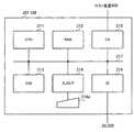
図2に示すストレージシステム100は、CE(Controller Enclosure)200と、DE(Drive Enclosure)300とを含む。また、CE200には、ホスト装置400が接続されている。[Second Embodiment]
FIG. 2 is a diagram illustrating an example of the overall configuration of the storage system according to the second embodiment.
The
CE200は、CM(Controller Module)201,202を備える。CM201,202のそれぞれは、ホスト装置400からのI/O(In/Out)要求に応じて、DE300内の記憶装置に対するデータの読み書きを行う。CM201,202は、DE300内の記憶装置によって実現される物理記憶領域をRAIDによって管理し、これらの物理記憶領域に対するアクセスを制御する。 The
なお、CM201,202は、例えばルータなどを介して互いに接続されていてもよい。また、CMは、CE200内に1つのみ設けられてもよいし、3つ以上設けられてもよい。ただし、CMが複数設けられることで、DE300に対するアクセス制御系統が冗長化され、アクセス制御処理の信頼性が向上する。 Note that the
DE300は、CM201,202からのアクセス制御対象となる複数の記憶装置を備える。本実施の形態において、DE300は、記憶装置としてHDDを備えるディスクアレイ装置である。なお、DE300が備える記憶装置としては、SSDなどの他の種類の不揮発性記憶装置を使用することもできる。また、CE200には、複数のDE300が接続されていてもよい。 The
ホスト装置400は、ユーザの操作に応じて、CM201,202に対して、DE300内のHDDへのアクセスを要求する。ホスト装置400は、例えば、ユーザの操作に応じて、CM201,202のいずれかを通じて、DE300内のHDDからのデータの読み出しや、DE300内のHDDに対するデータの書き込みを行うことができる。 The
なお、CE200内のCM201,202は、ともに同様の構成を有し、同様の処理を実行可能である。そこで、以下、CM201についてのみ説明し、CM202についての説明を省略する。 Note that the
図3は、CMのハードウェア構成例を示す図である。
CM201は、CPU211によって装置全体が制御されている。CPU211には、RAM(Random Access Memory)212および複数の周辺機器が、バス217を介して接続されている。RAM212は、CM201の主記憶装置として使用され、CPU211に実行させるプログラムの少なくとも一部や、このプログラムによる処理に必要な各種データを一時的に記憶する。FIG. 3 is a diagram illustrating a hardware configuration example of the CM.
The entire device of the
CPU211には、周辺機器の例として、SSD213、入力I/F(インタフェース)214、CA(Channel Adapter)215およびDI(Drive Interface)216が接続されている。 An
SSD213は、CM201の二次記憶装置として使用され、CPU211によって実行されるプログラムやその実行に必要な各種のデータなどを記憶する。なお、二次記憶装置としては、例えば、HDDなどの他の種類の不揮発性記憶装置が使用されてもよい。 The
入力I/F214には、操作キーなどを備える入力装置214aが接続されている。入力I/F214は、入力装置214aに対する操作入力に応じた信号をCPU211に出力する。 An
CA215は、ホスト装置400とCM201との間でデータを送受信するインタフェース処理を実行する。CA215とホスト装置400とは、例えば、FC(Fibre Channel)規格に従って通信する。 The
DI216は、DE300とCM201との間でデータを送受信するインタフェース処理を実行する。DI216とDE300とは、例えば、SAS(Serial Attached SCSI,SCSI:Small Computer System Interface)規格に従って通信する。 The
図4は、CMの処理機能の構成例を示すブロック図である。
CM201は、アクセス制御部220、リビルド制御部230およびサルベージ制御部240を備える。アクセス制御部220、リビルド制御部230およびサルベージ制御部240の処理は、例えば、CM201のCPU211が所定のプログラムを実行することで実現される。FIG. 4 is a block diagram illustrating a configuration example of a CM processing function.
The
また、CM201の記憶装置には、RAID管理テーブル250、バッドデータ(Bad Data)管理テーブル260、非冗長ライト管理テーブル270およびサルベージ管理テーブル280が記憶される。これらの各テーブルは、例えばSSD213に記憶される。 The storage device of the
アクセス制御部220は、ホスト装置400からのI/O要求に応じて、DE300内のHDDにアクセスする。アクセス制御部220は、例えば、ホスト装置400からデータの読み出し要求を受けたとき、要求されたデータをDE300内の所定のHDDから読み出して、ホスト装置400に送信する。一方、アクセス制御部220は、ホスト装置400からデータの書き込み要求を受けたとき、ホスト装置400から受信した書き込み対象のデータを、DE300内の所定のHDDに書き込む。 The
なお、以下の説明では、アクセス制御部220がホスト装置400からの読み出し要求に応じてHDDからデータを読み出すことを「ホストリードする」と呼ぶ。また、アクセス制御部220がホスト装置400からの書き込み要求に応じてHDDにデータを書き込むことを「ホストライトする」と呼ぶ。In the following description, reading data from the HDD in response to a read request from the
また、アクセス制御部220は、RAID管理テーブル250に設定された情報に基づいて、DE300内のHDDに記録するデータをRAIDによって管理する。アクセス制御部220は、RLU(RAID Logical Unit)ごとに記録データを所定のRAIDレベルによって管理する。RLUは、DE300に搭載された複数のHDDの物理記憶領域を組み合わせて構成される論理記憶領域であり、RAIDグループとも呼ばれる。 Further, the
RAID管理テーブル250は、RLUごとに、RLUの識別番号、適用されるRAIDレベル、RLUに属するHDDや論理ボリュームを示す情報、RLUの制御状態を示す情報などを保持する。アクセス制御部220は、RAID管理テーブル250を参照することで、例えば、ホストライトする際の書き込み先のHDDや、その書き込みの際に用いるRAIDレベルなどを判定する。なお、本実施の形態では、アクセス制御部220は、各RLUをデータが2重に冗長化されるRAIDレベルで管理する。データが2重に冗長化されるRAIDレベルとしては、例えば、RAID−1,RAID−4,RAID−5がある。 The RAID management table 250 holds, for each RLU, an RLU identification number, an applied RAID level, information indicating HDDs and logical volumes belonging to the RLU, information indicating the control status of the RLU, and the like. The
また、アクセス制御部220は、RLUに属するHDDのうちの1つが故障して、そのRLUに記録されたデータの冗長性が失われてから、ホットスペアのHDDに対するリビルド処理を開始するための準備が整うまでの期間に、そのRLUに対するホストライトを行ったとき、データの書き込み先の位置情報を非冗長ライト管理テーブル270に登録する。 In addition, the
リビルド制御部230は、RLUに属するHDDのうちの1つが故障したとき、故障したHDDに記録されていたデータをホットスペアのHDDに書き込む「リビルド処理」を実行する。リビルド制御部230は、リビルド処理の実行の際、RAID管理テーブル250を参照することで、故障したHDDに記録されていたデータをどのように生成するかを決定する。 When one of the HDDs belonging to the RLU fails, the
また、リビルド制御部230は、リビルド処理の実行中に、RLUに属するHDDのうち故障したHDD以外のHDDからのデータの読み出しに失敗すると、読み出しに失敗したデータの位置情報をバッドデータ管理テーブル260およびサルベージ管理テーブル280に登録するとともに、サルベージ制御部240に、読み出しに失敗したデータのサルベージを要求する。なお、アクセス制御部220は、バッドデータ管理テーブル260に登録された位置のデータについての読み出し要求をホスト装置400から受けたとき、ホスト装置400に対してエラー応答する。 If the
サルベージ制御部240は、リビルド制御部230によるリビルド処理において読み出しに失敗したデータをサルベージする。サルベージ管理テーブル280には、サルベージ処理の対象とされたデータ(すなわち、リビルド処理において読み出しに失敗したデータ)についての位置情報が登録されている。サルベージ制御部240は、サルベージ管理テーブル280に登録された位置情報に対応するデータについて順にサルベージ処理を実行することで、リビルド処理に対して非同期でサルベージ処理を実行できる。また、サルベージ制御部240は、非冗長ライト管理テーブル270などを参照しながら、後述するいくつかの処理パターンに従ってデータのサルベージを試みる。 The
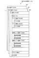
図5は、RAID管理テーブルに登録される情報の例を示す図である。
RAID管理テーブル250には、RLUごとにレコード251が登録される。各レコード251には、対応するRLUを識別するRLU番号が付与されている。以下の説明では、xx番のRLU番号を「RLU#xx」と表記し、RLU番号が「RLU#xx」であるRLUを、単に「RLU#xx」と呼ぶ。FIG. 5 is a diagram illustrating an example of information registered in the RAID management table.
In the RAID management table 250, a
各レコード251には、「RAIDレベル」、「ディスク番号」、「論理ユニット番号」、「HSディスク番号」および「RAID状態」が登録される。
「RAIDレベル」は、対応するRLUの通常運用時におけるRAIDレベルを示す。本実施の形態では、「RAIDレベル」には、RAID−1,RAID−4,RAID−5のいずれかが設定される。In each record 251, “RAID level”, “disk number”, “logical unit number”, “HS disk number”, and “RAID status” are registered.
“RAID level” indicates a RAID level during normal operation of the corresponding RLU. In the present embodiment, any one of RAID-1, RAID-4, and RAID-5 is set as the “RAID level”.
「ディスク番号」は、対応するRLUを構成する物理記憶領域が属するHDDの識別番号を示す。RLUは、複数のHDDの物理記憶領域によって構成されるので、「ディスク番号」は、それらの複数のHDDのそれぞれについて登録される。なお、以下の説明では、xx番のディスク番号を「DISK#xx」と表記し、ディスク番号が「DISK#xx」であるHDDを、単に「DISK#xx」と呼ぶ。 “Disk number” indicates the identification number of the HDD to which the physical storage area constituting the corresponding RLU belongs. Since the RLU is composed of physical storage areas of a plurality of HDDs, a “disk number” is registered for each of the plurality of HDDs. In the following description, the disk number xx is expressed as “DISK # xx”, and the HDD whose disk number is “DISK # xx” is simply referred to as “DISK # xx”.
また、「ディスク番号」によって識別されるHDDのそれぞれには、「ディスク状態」が登録される。「ディスク状態」は、対応するHDDの動作状態を示す。「ディスク状態」には、例えば、「正常」、「故障」および「HSに退避中」のいずれかが設定される。「正常」は、対応するHDDが正常に動作していることを示し、「故障」は、対応するHDDが故障していることを示す。「HSに退避中」は、対応するHDDに記録されていたデータについてのホットスペアのHDDへのリビルド処理が完了し、そのホットスペアのHDDを組み込んでRLUが運用されていることを示す。 Also, “disk status” is registered in each HDD identified by “disk number”. “Disk status” indicates the operating status of the corresponding HDD. For example, one of “normal”, “failure”, and “saving to HS” is set in the “disk state”. “Normal” indicates that the corresponding HDD is operating normally, and “Fail” indicates that the corresponding HDD has failed. “Saving to HS” indicates that the rebuild process to the hot spare HDD for the data recorded in the corresponding HDD has been completed, and that the RLU is operated by incorporating the hot spare HDD.
「論理ユニット番号」は、対応するRLUに設定された、論理ユニット(または論理ボリューム)と呼ばれる論理記憶領域の識別番号を示す。1つのRLUには複数の論理ユニットを設定可能であり、「論理ユニット番号」は、設定された論理ユニットごとに登録される。なお、以下の説明では、論理ユニット番号を「LUN」と省略して呼ぶ。また、xx番の論理ユニットを「LUN#xx」と表記し、論理ユニット番号が「LUN#xx」である論理ユニットを、単に「LUN#xx」と呼ぶ。 The “logical unit number” indicates an identification number of a logical storage area called a logical unit (or logical volume) set in the corresponding RLU. A plurality of logical units can be set in one RLU, and the “logical unit number” is registered for each set logical unit. In the following description, the logical unit number is abbreviated as “LUN”. In addition, the logical unit with the number xx is represented as “LUN # xx”, and the logical unit with the logical unit number “LUN # xx” is simply referred to as “LUN # xx”.
また、「論理ユニット番号」によって識別される論理ユニットのそれぞれには、「論理領域情報」および「物理領域情報」が登録される。「論理領域情報」には、論理ユニットに付与された論理アドレス(LBA:Logical Block Address)の範囲が登録される。「物理領域情報」には、論理ユニットに対して割り当てられた、各HDDにおける物理アドレスの範囲が登録される。 Further, “logical area information” and “physical area information” are registered in each of the logical units identified by the “logical unit number”. In the “logical area information”, a range of logical addresses (LBA: Logical Block Address) assigned to the logical units is registered. In the “physical area information”, the range of physical addresses assigned to each logical unit in each HDD is registered.
なお、CM201は、アクセス先とするデータのLUNおよびLBAが指定されると、LUNが示す論理ユニットが属するRLUのRAIDレベルと、その論理ユニットに割り当てられたHDDの物理領域情報とから、データのアクセス先とするHDDやHDD内のブロックの位置(ストライプ番号など)を特定することができる。 When the LUN and LBA of the data to be accessed are specified, the
「HSディスク番号」は、リビルド処理中のみ設定され、リビルド先とされているホットスペアのHDDを識別する番号を示す。
「RAID状態」は、対応するRLUの状態を示す。「RAID状態」には、例えば、「通常運用状態」、「非冗長状態」、「リビルド中」および「HSに退避中」のいずれかが設定される。The “HS disk number” is a number that is set only during the rebuild process and identifies the hot spare HDD that is the rebuild destination.
“RAID status” indicates the status of the corresponding RLU. For example, any one of “normal operation state”, “non-redundant state”, “rebuilding”, and “saving to HS” is set in the “RAID state”.
「通常運用状態」は、RLUに属するいずれのHDDにも異常がなく、データの冗長性を有する状態でRLUが正常に運用されていることを示す。「非冗長状態」は、RLUに属するいずれか1つのHDDが故障し、データの冗長性がない状態を示す。ただし、データの冗長性がない状態でも、「HSディスク番号」にホットスペアのHDDの識別番号が登録されて、リビルド処理の準備が整ってから、リビルド処理が完了するまでの間、「RAID状態」には「リビルド中」が設定される。「HSに退避中」は、ホットスペアのHDDへのリビルド処理が完了し、そのホットスペアのHDDを組み込んでRLUが運用されている状態を示す。 “Normal operation state” indicates that there is no abnormality in any HDD belonging to the RLU, and the RLU is normally operated in a state having data redundancy. The “non-redundant state” indicates a state in which any one HDD belonging to the RLU has failed and there is no data redundancy. However, even when there is no data redundancy, the “RAID status” is from the time when the identification number of the hot spare HDD is registered in “HS disk number” and the rebuild process is ready until the rebuild process is completed. Is set to “Rebuilding”. “Saving to HS” indicates a state in which the rebuild process to the hot spare HDD is completed and the RLU is operated by incorporating the hot spare HDD.
図6は、バッドデータ管理テーブルに登録される情報の例を示す図である。
バッドデータ管理テーブル260には、リビルド制御部230またはサルベージ制御部240によってデータの読み出しが不可能と判定された、論理ユニット内のデータの位置情報が、論理ユニットの番号(LUN)と論理アドレス(LBA)との組み合わせとして登録される。FIG. 6 is a diagram illustrating an example of information registered in the bad data management table.
In the bad data management table 260, the position information of the data in the logical unit, which is determined to be unreadable by the
本実施の形態では、リビルド処理中にデータの読み出しに失敗すると、読み出しに失敗したデータに対応するLUNおよびLBAが、リビルド制御部230によってバッドデータ管理テーブル260に登録される。また、バッドデータ管理テーブル260に登録されたデータについてのサルベージ処理が成功した場合には、そのデータに対応する位置情報はバッドデータ管理テーブル260から消去される。一方、サルベージ処理が不可能であった場合、そのデータについての位置情報はバッドデータ管理テーブル260に登録されたままになる。 In this embodiment, when data reading fails during the rebuild process, the LUN and LBA corresponding to the data that failed to be read are registered in the bad data management table 260 by the
なお、バッドデータ管理テーブル260のデータ構造は、図6の例に限らず、例えば、LUNごとの全LBAに対して、読み出し失敗が発生したか否かを示すフラグ情報が対応付けられた構造であってもよい。また、バッドデータ管理テーブル260には、位置情報として、LUNおよびLBAの代わりに、例えば、HDDのディスク番号およびHDDにおける物理アドレスが登録されてもよい。 Note that the data structure of the bad data management table 260 is not limited to the example of FIG. 6, for example, a structure in which flag information indicating whether or not a read failure has occurred is associated with all LBAs for each LUN. There may be. Further, in the bad data management table 260, for example, the HDD disk number and the physical address in the HDD may be registered as position information instead of the LUN and LBA.
図7は、非冗長ライト管理テーブルに登録される情報の例を示す図である。
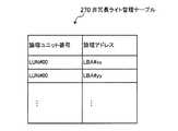
非冗長ライト管理テーブル270には、RLUのRAID状態が「非冗長状態」であるときに、そのRLUに属する論理ユニットに対してホストライトが実行されたとき、書き込み先の位置を示す情報が、LUNとLBAとの組み合わせとして登録される。FIG. 7 is a diagram illustrating an example of information registered in the non-redundant write management table.
In the non-redundant write management table 270, when the RAID state of the RLU is “non-redundant state”, when the host write is executed for the logical unit belonging to the RLU, the information indicating the write destination position is Registered as a combination of LUN and LBA.
なお、非冗長ライト管理テーブル270のデータ構造は、図7の例に限らず、例えば、論理ユニットごとの全LBAに対して、「非冗長状態」におけるホストライトが実行されたか否かを示すフラグ情報が対応付けられた構造であってもよい。また、非冗長ライト管理テーブル270には、位置情報として、LUNおよびLBAの代わりに、例えば、HDDのディスク番号およびHDDにおける物理アドレスが登録されてもよい。 Note that the data structure of the non-redundant write management table 270 is not limited to the example of FIG. 7. For example, a flag indicating whether or not a host write in the “non-redundant state” has been executed for all LBAs for each logical unit. A structure in which information is associated may be used. Further, in the non-redundant write management table 270, for example, the HDD disk number and the physical address in the HDD may be registered as the position information instead of the LUN and LBA.
図8は、サルベージ管理テーブルに登録される情報の例を示す図である。
サルベージ管理テーブル280は、サルベージ処理の対象とするデータを示す情報を一時的に保持することで、サルベージ制御部240がサルベージ処理をリビルド処理とは非同期に実行できるようにするものである。サルベージ管理テーブル280には、サルベージ処理の対象とするデータ(すなわち、リビルド処理時に読み出しに失敗したデータ)を示す位置情報が、論理ユニットの番号(LUN)、論理アドレス(LBA)およびディスク番号の組み合わせとして登録される。FIG. 8 is a diagram illustrating an example of information registered in the salvage management table.
The salvage management table 280 temporarily holds information indicating data to be salvaged so that the
なお、サルベージ管理テーブル280には、LUNおよびLBAの代わりに、ディスク番号が示すHDDにおける物理アドレスが登録されてもよい。また、サルベージ処理に対象とするデータが通常時にRAID−1で管理されているデータである場合、サルベージ管理テーブル280には、ディスク番号のようなHDDを識別する情報が登録されなくてもよい。なぜなら、RAID−1で管理されている場合、サルベージ制御部240は、データの読み出しに失敗したHDDが、RLUに属する2台のHDDのうち故障していないHDDであることを、容易に判別可能であるからである。 In the salvage management table 280, a physical address in the HDD indicated by the disk number may be registered instead of the LUN and LBA. Further, when the data targeted for salvage processing is data that is normally managed by RAID-1, the salvage management table 280 does not have to register information for identifying the HDD such as the disk number. This is because, when managed by RAID-1, the
図9は、HDDにおけるデータ記録フォーマットの例を示す図である。
DE300内の各HDDに記録されるデータは、一定長のブロックに分割される。また、各HDDにおいては、ブロックが格納されるブロック領域に対してBCC(Block Check Code)が付与されている。通常、BCCには誤り検出コードが記録され、ブロックが読み出されるとき、そのブロックに対応するBCCを基に、読み出されるブロックの整合性がチェックされる。また、BCCには、対応するブロック領域の属性を示す情報を記録しておくこともできる。例えば、リビルド先となるホットスペアのHDDにおいては、リビルド処理中にブロック領域に書き込むべきデータを生成できなかった場合、そのブロック領域に対応するBCCに、「バッドデータ」を示す情報が書き込まれる。FIG. 9 is a diagram showing an example of a data recording format in the HDD.
Data recorded on each HDD in the
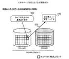
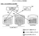
次に、サルベージ処理について説明する。まず、図10は、サルベージ処理が起動される状態の例を示す図である。この図10では例として、RAID−1の場合について説明する。 Next, the salvage process will be described. First, FIG. 10 is a diagram illustrating an example of a state in which the salvage process is activated. In FIG. 10, the case of RAID-1 will be described as an example.
図10の「状態1」において、RLU#00は、DISK#00,#01の各記憶領域によって構成され、これらの記憶領域がRAID−1で管理されている。この状態で、DISK#01の故障が発生すると(ステップS11)、リビルド制御部230は、DISK#01に記録されていたRLU#00のデータをホットスペアのDISK#10に格納するリビルド処理を実行する(ステップS12)。RLU#00にはRAID−1が設定されているので、リビルド処理では、DISK#00に記録されているRLU#00のデータがそのまま読み出されて、ホットスペアのDISK#10にコピーされる。 In “
ここで、リビルド処理が正常に完了すると、DISK#01に記録されていたRLU#00のデータがホットスペアのDISK#10に完全に復元される。このとき、故障したDISK#01の代わりにホットスペアのDISK#10がRLU#00に組み込まれることで、アクセス制御部220は、RLU#00におけるデータの冗長性が完全に回復した状態で、ホストリードやホストライトを続行できる。 Here, when the rebuild process is completed normally, the data of
しかしながら、図10の「状態2」のように、リビルド処理の実行中に、リビルド制御部230がDISK#00中のあるブロックからのデータ読み出しに失敗すると(ステップS13)、読み出しに失敗したデータをホットスペアのDISK#10にコピーすることができなくなり、このデータを失ってしまう。これに対して、サルベージ制御部240は、読み出しに失敗したデータのサルベージ処理を行い、ホットスペアのDISK#10における対応する位置にリビルドデータが格納されるようにする。 However, as shown in “state 2” in FIG. 10, if the
具体的には、リビルド制御部230は、リビルド処理中にDISK#00からのデータ読み出しに失敗すると、読み出しに失敗したデータの位置情報をサルベージ管理テーブル280に登録する(ステップS14)。サルベージ制御部240は、サルベージ管理テーブル280に登録された位置情報が示すデータについてのサルベージ処理を実行する。 Specifically, if the data read from
また、リビルド制御部230は、読み出しに失敗したデータの位置情報をバッドデータ管理テーブル260にも登録する(ステップS15)。アクセス制御部220は、バッドデータ管理テーブル260に登録された位置情報に対応するデータに対する読み出し要求を、ホスト装置400から受信したとき、ホスト装置400に対してエラー応答する。これにより、アクセス制御部220による、データの読み出しに失敗したデータへの無駄なアクセスの発生が防止される。 In addition, the
なお、この時点では、バッドデータ管理テーブル260に対して位置情報が登録されなくてもよい。例えば、読み出しに失敗したデータについてのサルベージが不可能であったときに、サルベージ制御部240によってバッドデータ管理テーブル260に位置情報が登録されてもよい。 At this time, the position information may not be registered in the bad data management table 260. For example, the position information may be registered in the bad data management table 260 by the
なお、上記のステップS14,S15の処理順は、逆であってもよいし、あるいは並列に実行されてもよい。
ところで、前述のように、リビルド処理とは、故障したHDDに記録されていたデータを、リビルド先のHDD(本実施の形態ではホットスペアのHDD)に格納することである。図10の例のように、RAID−1のRLUにおけるリビルド処理では、故障していないHDDから読み出されたデータが、そのままリビルド先のHDDにコピーされる。Note that the processing order of the above steps S14 and S15 may be reversed, or may be executed in parallel.
By the way, as described above, the rebuild process is to store the data recorded in the failed HDD in the rebuild destination HDD (in this embodiment, a hot spare HDD). As in the example of FIG. 10, in the rebuild process in the RAID-1 RLU, the data read from the HDD that has not failed is directly copied to the rebuild destination HDD.
サルベージ処理とは、本来、リビルド処理時に読み出しの失敗が発生した場合でも、何らかの方法により、故障したHDDに記録されていたデータがリビルド先のHDDに格納された状態にすることである。しかしながら、RAID−1のRLUにおけるサルベージ処理は、読み出しに失敗したデータと同じデータが、リビルド先のHDDに格納された状態にすることと同等である。 The salvage process is to make the data recorded in the failed HDD stored in the rebuild destination HDD by some method even when a read failure occurs during the rebuild process. However, the salvage process in the RAID-1 RLU is equivalent to setting the same data as the data that failed to be read in the rebuild destination HDD.
これに対して、RAID−4,5のRLUにおけるリビルド処理では、故障したHDDに記録されていたデータは、故障していない他のHDDから読み出したデータを基に計算によってリビルドされる。このため、RAID−4,5のRLUにおけるサルベージ処理は、RAID−1の場合とは異なり、読み出しに失敗したデータと同じデータがリビルド先のHDDに格納された状態にすることとは同等でない。 On the other hand, in the rebuild process in the RLUs of RAID-4 and 5, the data recorded in the failed HDD is rebuilt by calculation based on the data read from the other HDD that has not failed. For this reason, unlike the RAID-1 case, the salvage processing in the RLUs of RAID-4 and 5 is not equivalent to the state in which the same data as the data that failed to be read is stored in the rebuild destination HDD.
そこで、以下の説明では、主としてRAID−1のRLUにおけるサルベージ処理の手順について説明し、必要に応じて、RAID−4,5のRLUにおけるサルベージ処理の手順についても補足説明する。なお、RAID−4,5の場合について補足説明する場合には、RLUがDISK#00〜#04の記憶領域によって構成されるものとする。 Therefore, in the following description, the salvage processing procedure in the RAID-1 RLU will be mainly described, and the salvage processing procedure in the RAID-4, 5 RLU will be supplementarily described as necessary. Note that in the case of supplementary explanation about the cases of RAID-4 and 5, it is assumed that the RLU is constituted by the storage areas of
サルベージ制御部240は、次のサルベージ方法(1)〜(3)を利用してサルベージ処理を実行する。
サルベージ方法(1):ホットスペアのHDDに記録されたデータを基にサルベージする。The
Salvage method (1): Salvage is performed based on data recorded in a hot spare HDD.
サルベージ方法(2):故障したHDDを再起動させ、少なくとも再起動したHDDから読み出したデータを基にサルベージする。
サルベージ方法(3):データの読み出しに失敗したHDDを再起動させ、少なくとも再起動したHDDから読み出したデータを基にサルベージする。Salvage method (2): A failed HDD is restarted, and salvage is performed based on at least data read from the restarted HDD.
Salvage method (3): The HDD that failed to read data is restarted, and salvage is performed based on at least the data read from the restarted HDD.
以下、上記のサルベージ方法(1)〜(3)について、詳細に説明する。
図11は、サルベージ方法(1)の実行に必要な前処理を示す図である。
図11の「状態11」は、図10の「状態1」と同様に、RLU#00を構成するDISK#01の故障が発生した場合を示す。このとき、リビルド制御部230は、リビルド先とするホットスペアのHDDを選択するが、リビルド先とするホットスペアのHDDの全記憶領域を、あらかじめBCCエラー状態にしておく。ここで言うBCCエラー状態とは、ブロックのデータを読み出したときに、そのブロックに対応するBCCから読み出しエラーが検出されるように、BCCに何らかの値が設定されている状態である。ただし、BCCエラー状態では、BCCには、前述したバッドデータを示す情報以外の値が設定されることが望ましい。BCCエラー状態と、BCCがバッドデータを示す状態とを区別することで、BCCがバッドデータを示したとき、そのBCCに対応するブロックのデータについてはサルベージが不可能であったことを明確に認識できるようになる。Hereinafter, said salvage methods (1)-(3) are demonstrated in detail.
FIG. 11 is a diagram showing pre-processing necessary for execution of the salvage method (1).
“
ところで、アクセス制御部220は、DISK#01が故障した後も、データの冗長性がない状態のままで、残りのDISK#00を用いてRLU#00に対するホストリードおよびホストライトを継続する。ただし、図11の「状態12」に示すように、リビルド先とするホットスペアのDISK#10の準備が整ってから(具体的には、RAID管理テーブル250におけるRLU#00に対応するレコード251内の「HSディスク番号」にDISK#10が設定されてから)、リビルド処理が完了するまでの期間、アクセス制御部220は、ホスト装置400から書き込み要求を受けたとき(ステップS21)、DISK#00だけでなく、リビルド先のDISK#10に対してもホストライトを行う(ステップS22,S23)。 By the way, the
RLU#00がRAID−1の場合、「状態12」では、ホスト装置400から書き込み要求されたデータをDISK#00に書き込む(ステップS22)とともに、同じデータを、ホットスペアのDISK#10における対応するブロックにも書き込む(ステップS23)。ホットスペアのDISK#10では、データが書き込まれたブロックに対応するBCCに誤り検出コードが上書きされ、このブロックは正常に読み出し可能な状態になる。これにより、もしDISK#10におけるホストライトされたブロックについて、リビルド処理が実行されていない場合でも、そのブロックには最新の書き込みデータが格納されていることになる。 When the
ここで、RLU#00がRAID−4,5のいずれかの場合について補足説明する。RAID−4,5のいずれかで運用されるRLUがDISK#00〜#04の各記憶領域によって構成されている場合、通常運用時のホストライトは次のように行われる。アクセス制御部220は、書き込みを要求されたデータを一定長に分割する。アクセス制御部220は、例えば、連続する分割データD0〜D3を基にパリティP0を計算する。RAID−4の場合、アクセス制御部220は、分割データD0〜D3およびパリティP0を、それぞれあらかじめ決められたHDDに書き込む。一方、RAID−5の場合、アクセス制御部220は、分割データD0〜D3およびパリティP0を、DISK#00〜#04に分散させて書き込む。 Here, a supplementary description will be given of the case where
例えばDISK#04が故障した状態で、新たな分割データD0〜D3の書き込みが要求された場合、図11の「状態12」に示す前処理は次のように行われる。例えば、DISK#04に書き込むべきデータが分割データD3である場合、アクセス制御部220は、他のDISK#00〜#03に、分割データD0〜D2、および、これらの分割データに基づくパリティP0を書き込む(ステップS22)とともに、分割データD3をDISK#10に書き込む(ステップS23)。また、例えば、DISK#04に書き込むべきデータがパリティP0である場合、アクセス制御部220は、他のDISK#00〜#03に、分割データD0〜D3を書き込む(ステップS22)とともに、分割データD0〜D3に基づくパリティP0を計算して、算出したパリティP0をDISK#10に書き込む(ステップS23)。 For example, when writing of new divided data D0 to D3 is requested in a state where DISK # 04 has failed, the preprocessing shown in “
ただし、分割データD0〜D3のうち例えば分割データD3のみが更新される場合には、分割データD0〜D2が記録されたHDDに対しては書き込みが行われない。従ってこの場合、故障したDISK#04に対する書き込みが必ず行われる訳ではなく、DISK#04に分割データD3またはパリティP0が書き込まれる場合のみ、DISK#10に分割データD3またはパリティP0が書き込まれることになる。 However, when only the divided data D3 is updated among the divided data D0 to D3, for example, writing is not performed on the HDD in which the divided data D0 to D2 is recorded. Therefore, in this case, writing to the failed DISK # 04 is not necessarily performed, and only when the divided data D3 or the parity P0 is written to the DISK # 04, the divided data D3 or the parity P0 is written to the
すなわち、RAID−1,4,5のいずれの場合でも、図11の「状態12」に示す前処理では、アクセス制御部220は、ホスト装置400から書き込みが要求されたとき、故障したHDDに書き込むべきデータがある場合には、そのデータをホットスペアのHDDに書き込む。 That is, in any case of RAID-1, 4, and 5, in the preprocessing shown in “
図12は、サルベージ方法(1)の手順を示す図である。
リビルド制御部230は、DISK#01に記録されたデータについてのリビルド処理の際、図11の「状態12」のような、ホスト装置400からの要求に応じた書き込みがあったか否かに関係なく、DISK#00内の読み出し対象領域の全域からのデータ読み出しを行う。図12の「状態13」に示すように、リビルド制御部230による、DISK#01に記録されたデータについてのリビルド処理が実行されているときに、DISK#00上のあるブロックからのデータ読み出しに失敗したとする(ステップS24)。この場合、サルベージ制御部240は、読み出しに失敗したブロックに対応する、ホットスペアのDISK#10のブロックに、データが書き込まれているかを判定する。この判定処理は、DISK#10の対応するブロックからのデータ読み出しに成功するか否かによって行われる(ステップS25)。DISK#10のブロックからのデータ読み出しに成功した場合、そのブロックにはホストライトによる最新のデータがすでに格納されていることになるので、サルベージ制御部240は、データのサルベージに成功したと判断する。一方、DISK#10のブロックからのデータ読み出し時にBCCエラーが検出された場合、サルベージ制御部240は、データのサルベージに失敗したと判断する。この場合、サルベージ制御部240は、他のサルベージ方法を試みる。FIG. 12 is a diagram showing the procedure of the salvage method (1).
The
なお、以上の図12に示したサルベージ方法(1)の手順は、RLU#00がRAID−4,5のいずれかの場合でも同様である。すなわち、サルベージ制御部240は、ホットスペアのDISK#10における対応するブロック(読み出しに失敗したブロックと同じストライプ番号のブロック)からのデータ読み出しに成功した場合、データのサルベージに成功したと判断する。 The procedure of the salvage method (1) shown in FIG. 12 is the same even when
次に、図13は、サルベージ方法(2),(3)の実行に必要な前処理を示す図である。
図13の「状態21」は、図10の「状態1」と同様に、RLU#00を構成するDISK#01の故障が発生した場合を示す。ただし、「状態21」は、DISK#01が故障してから、リビルド先とするホットスペアのDISK#10の準備が整うまで(具体的には、RAID管理テーブル250におけるRLU#00に対応するレコード251内の「HSディスク番号」にDISK#10が設定されるまで)の状態を示す。この「状態21」では、アクセス制御部220は、DISK#00のみを用いてRLU#00に対するホストリードおよびホストライトを継続する。Next, FIG. 13 is a diagram showing preprocessing necessary for executing the salvage methods (2) and (3).
“
サルベージ方法(2),(3)の前処理として、アクセス制御部220は、「状態21」においてホスト装置400からRLU#00に対する書き込み要求を受けると(ステップS31)、DISK#00の対応するブロックにデータを書き込む。これとともに、アクセス制御部220は、データの書き込み位置を示す位置情報(データを書き込んだブロックに対応するLUNおよびLBA)を、非冗長ライト管理テーブル270に登録する(ステップS32)。 As pre-processing of the salvage methods (2) and (3), when the
「状態21」においてホストライトが発生すると、書き込まれるデータは冗長性がない状態となる。従って、非冗長ライト管理テーブル270には、RLU#00に記録されたデータのうち冗長性のないデータの位置情報が登録されることになる。 When a host write occurs in “
なお、以上の「状態21」に示した前処理の手順は、RLU#00がRAID−4,5のいずれかの場合でも同様であり、アクセス制御部220は、ホストライトした位置の情報を非冗長ライト管理テーブル270に登録する。 Note that the pre-processing procedure shown in the above “
図14は、サルベージ方法(2)の手順を示す図である。
図14の「状態22」は、図13の「状態21」から、ホットスペアのDISK#10に対するリビルド処理が開始された状態を示す。RLU#00がRAID−1の場合、リビルド制御部230は、DISK#00に記録されたRLU#00のデータを読み出して、DISK#10にコピーする。このようなリビルド処理中に、リビルド制御部230が、DISK#00からのデータ読み出しに失敗したものとする(ステップS33)。FIG. 14 is a diagram showing the procedure of the salvage method (2).
“
サルベージ制御部240は、DISK#01が故障してから現在までの間に、DISK#00における読み出しに失敗したブロック、またはそのブロックに対応するDISK#10のブロックの少なくとも一方に対して、ホストライトが行われたかを判定する。具体的には、サルベージ制御部240は、前述のサルベージ方法(1)においてホットスペアのDISK#10における対応するブロックからのデータ読み出しに失敗し、かつ、非冗長ライト管理テーブル270に、読み出しに失敗したブロックに対応する位置に対してホストライトが行われたことが登録されていない場合に、DISK#00,#10の少なくとも一方における対応するブロックに対してDISK#01の故障から現在までにホストライトが行われていないと判定する(ステップS34)。 The
ホストライトが行われていないと判定された場合、DISK#00からの読み出しに失敗したデータに対応する、ホットスペアのDISK#10にリビルドすべきデータは、故障したDISK#01にのみ存在する可能性が高い。このことから、サルベージ制御部240は、故障したDISK#01を再起動させ(ステップS35)、再起動したDISK#01から、DISK#10にリビルドするデータを読み出すことができるかを試す。 If it is determined that the host write has not been performed, the data to be rebuilt in the hot
図14の「状態23」に示すように、サルベージ制御部240は、読み出しに失敗したDISK#00のブロックに対応する、再起動したDISK#01のブロックから、データを読み出す。データの読み出しに成功した場合、サルベージ制御部240は、読み出したデータを、ホットスペアのDISK#10における同じストライプ番号に対応するブロックにコピーする。この場合、データのサルベージに成功したことになる(ステップS36)。 As shown in “state 23” in FIG. 14, the
なお、以上の図14に示したサルベージ方法(2)の手順は、RLU#00がRAID−4,5のいずれかの場合でも同様である。すなわち、サルベージ制御部240は、再起動したDISK#01における対応するブロックからのデータの読み出しに成功すると、読み出したデータを、ホットスペアのDISK#10における同じストライプ番号のブロックにコピーする。 The procedure of the salvage method (2) shown in FIG. 14 is the same even when
図15は、サルベージ方法(3)の手順を示す図である。
図13の「状態21」からリビルド処理が開始され、リビルド処理中に、リビルド制御部230がDISK#00からのデータ読み出しに失敗したものとする(ステップS41)。サルベージ制御部240は、図15の「状態31」に示すように、非冗長ライト管理テーブル270に、読み出しに失敗したブロックに対応する位置に対してホストライトが行われたことが登録されているかを判定する。FIG. 15 is a diagram illustrating the procedure of the salvage method (3).
It is assumed that the rebuild process is started from “
非冗長ライト管理テーブル270にホストライトが行われたことが登録されていた場合、読み出しに失敗したデータに対応するDISK#01のブロックには、最新のデータが登録されていない。これとともに、読み出しに失敗したデータに対応するDISK#10のブロックには、データが記録されておらず、このブロックはBCCエラー状態になっているはずである。このことから、サルベージ制御部240は、読み出しに失敗したものの、最新のデータが残っている可能性のあるDISK#00を再起動させ(ステップS43)、再起動したDISK#00における読み出し失敗位置から、データの読み出しを再度試みる。例えば、リビルド処理におけるデータ読み出しの失敗要因が一時的なものである場合などに、再起動後のデータ読み出しに成功する可能性がある。 When it is registered in the non-redundant write management table 270 that the host write has been performed, the latest data is not registered in the
図15の「状態32」に示すように、サルベージ制御部240は、再起動したDISK#00における読み出し失敗位置からのデータの読み出しに成功した場合、読み出したデータを基に、DISK#10に記録すべきデータをサルベージする(ステップS44)。RAID−1の場合、サルベージ制御部240は、再起動したDISK#00から読み出したデータを、ホットスペアのDISK#10における対応するブロックにコピーする。 As shown in “state 32” in FIG. 15, when the
なお、RLU#00がRAID−4,5のいずれかであり、RLU#00の記憶領域がDISK#00〜DISK#04で構成され、DISK#04が故障し、DISK#00からのデータ読み出しに失敗したものとすると、「状態32」のステップS44では、次のような処理が実行される。サルベージ制御部240は、サルベージ管理テーブル280に登録された位置情報を基に、データの読み出しに失敗したHDDを判別し、判別したHDD(ここではDISK#00)を再起動させる。サルベージ制御部240は、再起動したDISK#00から読み出したデータと、残りの故障していないDISK#01〜03における同じストライプ番号に対応するブロックから読み出したデータとを基に、ホットスペアのDISK#10に格納すべきデータを生成する。 Note that
例えば、DISK#00から分割データD0の読み出しに失敗し、この分割データD0に対応するパリティP0が故障したDISK#04に記録されているとする。この場合、サルベージ制御部240は、再起動したDISK#00から読み出した分割データD0と、残りの故障していないDISK#01〜03から読み出した分割データD1〜D3とを基に、パリティP0を計算し、ホットスペアのDISK#10に格納する。 For example, it is assumed that reading of the divided data D0 from the
また、例えば、DISK#00から分割データD0の読み出しに失敗し、故障したDISK#04に分割データD3が記録されているとする。この場合、サルベージ制御部240は、再起動したDISK#00から読み出した分割データD0と、残りの故障していないDISK#01〜03から読み出した分割データD1,D2およびパリティP0から、分割データD3を計算し、ホットスペアのDISK#10に格納する。 Further, for example, it is assumed that reading of the divided data D0 from the
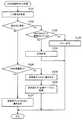
次に、上記のサルベージ方法(1)〜(3)を用いたサルベージ処理について、フローチャートを用いて説明する。まず、図16は、リビルド処理手順の例を示すフローチャートである。 Next, the salvage process using the above salvage methods (1) to (3) will be described with reference to a flowchart. First, FIG. 16 is a flowchart illustrating an example of the rebuild processing procedure.
[ステップS101]アクセス制御部220は、DE300内のHDDが故障したことを検出すると、故障したHDDのディスク番号と、そのHDDが属するRLUのRLU番号とを、リビルド制御部230に通知する。以下、RLU#00に属する1つのHDDが故障したものとして、説明を続ける。 [Step S101] Upon detecting that the HDD in the
アクセス制御部220からの通知を受けたリビルド制御部230は、RAID管理テーブル250からRLU#00のレコード251を抽出し、抽出したレコード251において、故障したHDDのディスク番号に対応する「ディスク状態」を「故障」に更新するとともに、「RAID状態」を「非冗長状態」に更新する。 The
故障したHDDのディスク番号に対応する「ディスク状態」が「故障」に更新されることで、故障したHDDはRLU#00から切り離される。なお、故障したHDDは、RLU#00から切り離された時点で、電源オフにされてもよい。あるいは、故障したHDDは、例えば、新たなHDDに交換される直前に電源オフにされてもよい。 By updating the “disk status” corresponding to the disk number of the failed HDD to “failed”, the failed HDD is disconnected from the
[ステップS102]リビルド制御部230は、リビルド先とするホットスペアのHDDを準備する。具体的には、リビルド制御部230は、リビルド先とするホットスペアのHDDを選択し、選択したHDDのディスク番号を、RAID管理テーブル250におけるRLU#00のレコード251の「HSディスク番号」に登録する。さらに、リビルド制御部230は、RLU#00のレコード251の「RAID状態」を「リビルド中」に更新する。これにより、ホットスペアのHDDの準備が完了し、リビルド処理を開始できる状態となる。 [Step S102] The
[ステップS103]リビルド制御部230は、RLU#00に属する論理ユニットからリビルド対象とするデータ領域を、所定数のLBA単位で選択する。リビルド制御部230は、選択したデータ領域に対応するデータのリビルドを実行する。 [Step S103] The
ここで言う「データのリビルド」とは、ホットスペアのHDDに対して格納するデータを生成することであり、以下、生成されたデータを「リビルドデータ」と呼ぶ。例えば、RLU#00が正常時にRAID−1で管理されている場合、リビルド制御部230は、RLU#00に属する故障していないHDDから単にデータを読み出すことで、リビルドデータを生成する。一方、RLU#00が正常時にRAID−4,5のいずれかで管理されている場合、リビルド制御部230は、RLU#00に属する故障していないHDDの同一ストライプ番号の位置からデータを読み出し、読み出しデータを基にした計算によってリビルドデータを生成する。 Here, “data rebuild” is to generate data to be stored in the hot spare HDD, and the generated data is hereinafter referred to as “rebuild data”. For example, when
[ステップS104]ステップS103でのリビルドデータの生成時に、故障していないHDDからのデータ読み出しに成功した場合(S104:No)、リビルド制御部230は、ステップS105の処理を実行する。一方、故障していないHDDからのデータ読み出しに失敗して、リビルドデータを生成できなかった場合(S104:Yes)、リビルド制御部230は、ステップS106の処理を実行する。 [Step S104] When rebuilding data is generated in Step S103, if the data reading from the HDD that has not failed is successful (S104: No), the rebuilding
[ステップS105]リビルド制御部230は、ステップS103で生成したリビルドデータを、ホットスペアのHDDにおける対応する領域に格納する。
[ステップS106]リビルド制御部230は、ステップS103で選択したデータ領域を示すLUNおよびLBAと、ステップS104でデータ読み出しに失敗したHDDのディスク番号とを、サルベージ管理テーブル280に登録する。また、リビルド制御部230は、ステップS103で選択したデータ領域を示すLUNおよびLBAを、バッドデータ管理テーブル260に登録する。なお、サルベージ管理テーブル280およびバッドデータ管理テーブル260のどちらに対して先に情報を登録するかは、特に限定されるものではない。[Step S105] The
[Step S106] The
[ステップS107]リビルド制御部230は、RLU#00に属する全論理ユニットの全データ領域についてリビルド処理を完了したかを判定する。全データ領域のリビルド処理を完了していない場合(S107:No)、リビルド制御部230は、ステップS103の処理に戻り、次のデータ領域についてのリビルド処理を実行する。一方、全データ領域のリビルド処理を完了した場合(S107:Yes)、リビルド制御部230は、ステップS108の処理を実行する。 [Step S107] The
[ステップS108]リビルド制御部230は、RLU#00についてのサルベージ制御部240によるサルベージ処理が完了したかを判定する。ここでは、リビルド制御部230は、サルベージ管理テーブル280にRLU#00に属する位置情報が登録されていない場合に、RLU#00についてのサルベージ処理が完了したと判定する。なお、RLU#00のリビルド処理時にデータの読み出しに失敗しなかった場合(すなわち、ステップS104で「No」と判定された場合)、サルベージ管理テーブル280には、RLU#00に属する位置情報は登録されない。[Step S108] The
RLU#00についてのサルベージ処理が完了したと判定する(S108:Yes)と、リビルド制御部230は、RAID管理テーブル250のRLU#00のレコード251において、故障したHDDに対応する「ディスク状態」を「HSに退避中」に更新するとともに、「RAID状態」を「HSに退避中」に更新する。これにより、リビルド処理が完了する。 If it is determined that the salvage process for
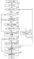
次に、図17は、アクセス制御部によるI/O処理手順の例を示すフローチャートである。この図17は、I/O処理対象のRLU#00に属する1つのHDDが故障してから、RLU#00のリビルド処理が完了するまでの期間におけるI/O処理を示す。この期間とは、RAID管理テーブル250のRLU#00のレコード251において、故障したHDDに対応する「ディスク状態」に「故障」が設定され、かつ、「RAID状態」が「非冗長状態」または「リビルド中」が設定されている期間である。 Next, FIG. 17 is a flowchart illustrating an example of an I / O processing procedure by the access control unit. FIG. 17 shows I / O processing in a period from when one HDD belonging to
[ステップS121]アクセス制御部220は、ホスト装置400から、RLU#00に対するI/O要求を受信する。
[ステップS122]I/O要求が読み出し要求である場合(S122:Yes)、ステップS123の処理が実行される一方、I/O要求が書き込み要求である場合(S122:No)、ステップS126の処理が実行される。[Step S121] The
[Step S122] If the I / O request is a read request (S122: Yes), the process of step S123 is executed, while if the I / O request is a write request (S122: No), the process of step S126. Is executed.
[ステップS123]ホスト装置400から読み出し要求を受信した場合(S122:Yes)、アクセス制御部220は、読み出し要求先のデータ領域の位置情報がバッドデータ管理テーブル260に登録されているかを判定する。アクセス制御部220は、対応する位置情報がバッドデータ管理テーブル260に登録されていなかった場合(S123:No)、ステップS124の処理を実行する。一方、アクセス制御部220は、対応する位置情報がバッドデータ管理テーブル260に登録されていた場合(S123:Yes)、ステップS125の処理を実行する。 [Step S123] When a read request is received from the host device 400 (S122: Yes), the
[ステップS124]アクセス制御部220は、読み出しを要求されたデータをHDDから読み出して、ホスト装置400に返信する。すなわち、アクセス制御部220は、ホスト装置400に対して正常応答する。 [Step S124] The
[ステップS125]アクセス制御部220は、ホスト装置400に対して、要求されたデータを正常に読み出すことができなかったとして、エラー応答する。
なお、ホスト装置400から読み出し要求を受信した場合(S122:Yes)、アクセス制御部220は、バッドデータ管理テーブル260を参照せずにデータの読み出しを実行してもよい。この場合、アクセス制御部220は、読み出しに成功した場合にはステップS124を実行する一方、読み出しに失敗した場合にはステップS125を実行する。ただし、読み出し対象のデータの位置情報がバッドデータ管理テーブル260に登録されている場合、そのデータの読み出しを正常に実行できない可能性が高い。このため、バッドデータ管理テーブル260を参照することで、アクセス制御部220による無駄なデータアクセスの実行を防止できる。[Step S125] The
Note that when a read request is received from the host device 400 (S122: Yes), the
[ステップS126]ホスト装置400から書き込み要求を受信した場合(S122:No)、アクセス制御部220は、リビルド先とするホットスペアのHDDの準備が完了しているかを判定する。具体的には、アクセス制御部220は、RAID管理テーブル250のRLU#00のレコード251において、「HSディスク番号」にホットスペアのHDDのディスク番号が設定されており、かつ、「RAID状態」に「リビルド中」が設定されている場合に、ホットスペアのHDDの準備が完了していると判定する。 [Step S126] When a write request is received from the host device 400 (S122: No), the
ホットスペアのHDDの準備が完了している場合(S126:Yes)、アクセス制御部220は、ステップS127の処理を実行する。一方、ホットスペアのHDDの準備が完了していない場合(S126:No)、アクセス制御部220は、ステップS128の処理を実行する。 When the preparation of the hot spare HDD is completed (S126: Yes), the
[ステップS127]アクセス制御部220は、RLU#00に属する故障していない所定のHDDに対して、書き込み処理を行う。また、アクセス制御部220は、故障したHDDに書き込むべきデータがある場合には、そのデータをホットスペアのHDDに書き込む。 [Step S127] The
このステップS127で実行される書き込み処理の内容は、図11の「状態12」で説明した通りである。ホットスペアのHDDに書き込みが行われた場合、書き込みが行われたブロックに対応するBCCには、ブロックに書き込まれたデータに基づく誤り検出コードが上書きされる。これにより、ブロックに書き込まれたデータが正常に読み出し可能な状態になるとともに、そのブロックに対応するLBAに対してリビルド処理中にホストライトがあったことを、サルベージ制御部240がサルベージ処理中に認識できるようになる。 The contents of the writing process executed in step S127 are as described in “
なお、例えば、このステップS127において、故障していないHDDに対するデータの書き込みが正常に行われなかったとしても、書き込みできなかったデータのサルベージを可能にするデータがホットスペアのHDDに書き込まれる。このため、後のリビルド処理時に、書き込みできなかった位置からのデータ読み出しに失敗した場合でも、サルベージ制御部240は、少なくともホットスペアのHDDに書き込まれたデータを基に、読み出しに失敗したデータをサルベージすることができる。 Note that, for example, in this step S127, even if data writing to the HDD that has not failed is not normally performed, data that enables salvage of data that could not be written is written to the hot spare HDD. For this reason, even when data read from a position where writing could not be performed fails during the subsequent rebuild process, the
[ステップS128]アクセス制御部220は、RLU#00に属する故障していない所定のHDDに対して、書き込み処理を行う。
[ステップS129]アクセス制御部220は、データの書き込み位置を示す位置情報(データを書き込んだブロックに対応するLUNおよびLBA)を、非冗長ライト管理テーブル270に登録する。[Step S128] The
[Step S129] The
なお、ステップS128,S129の処理の内容は、図13の「状態21」で説明した通りである。ステップS129の処理により、非冗長ライト管理テーブル270には、RLU#00に記録されたデータのうち冗長性のないデータの位置情報が登録されることになる。 Note that the contents of the processing in steps S128 and S129 are as described in “
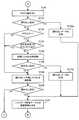
次に、図18は、サルベージ処理手順の例を示す図である。この図18の処理は、サルベージ制御部240が、サルベージ管理テーブル280に登録された位置情報を1つ選択するたびに実行される。また、サルベージ制御部240は、サルベージ管理テーブル280から選択した位置情報内のLUNが設定されたRLUを、RAID管理テーブル250を基に特定する。ここでは、RLU#00が特定されたものとして説明する。 Next, FIG. 18 is a diagram illustrating an example of a salvage processing procedure. The process of FIG. 18 is executed every time the
[ステップS141]サルベージ制御部240は、RAID管理テーブル250におけるRLU#00のレコード251内の「HSディスク番号」から、ホットスペアのHDD(ここではDISK#10とする)を認識する。サルベージ制御部240は、図12の「状態13」のステップS25と同様の手順で、位置情報から特定されるホットスペアのHDDのブロックから、データを読み出せるかを試す。この処理での読み出し位置は、RAID−1の場合、読み出しに失敗したブロックと同じデータが格納される、ホットスペアのHDDのブロックであり、RAID−4,5のいずれかの場合、読み出しに失敗したブロックと同じストライプ番号に対応する、ホットスペアのHDDのブロックである。[Step S141] The
[ステップS142]サルベージ制御部240は、ステップS141でのデータ読み出しに成功した場合には(S142:Yes)、ステップS151の処理を実行する。この場合、データのサルベージに成功したことになる。一方、サルベージ制御部240は、ステップS141でデータを読み出せなかった場合には(S142:No)、ステップS143の処理を実行する。 [Step S142] When the data read in step S141 is successful (S142: Yes), the
なお、データのサルベージに成功した場合、例えば、サルベージ制御部240はさらに、読み出しに失敗したHDDにおける対応するブロック(すなわち、リビルド処理時に読み出しに失敗したブロック)にも、データの書き込みを行ってもよい。RLU#00がRAID−1の場合、サルベージ制御部240は、ホットスペアのDISK#10から読み出したデータを、読み出しに失敗したHDDにおける対応するブロックに書き込む。一方、RLU#00がRAID−4,5のいずれかの場合、サルベージ制御部240は、RLU#00に属する故障していないHDDのうち読み出しに失敗したHDD以外のHDDから、読み出しに失敗したブロックと同じストライプ番号のブロックのデータを読み出す。サルベージ制御部240は、読み出したこれらのデータと、ホットスペアのDISK#10から読み出したデータとを基に、読み出しに失敗したデータを計算し、算出されたデータを読み出しに失敗したHDDにおける同じストライプ番号のブロックに書き込む。 When the data salvage is successful, for example, the
[ステップS143]ステップS141でのデータ読み出しでBCCエラーが検出された場合(S143:Yes)、ステップS144の処理が実行される。一方、ステップS141でデータを読み出せなかった要因がBCCエラー以外の要因である場合(ステップS143:No)、ステップS148の処理が実行される。なお、後者の場合の例としては、ホットスペアのDISK#10が故障している場合などがある。 [Step S143] If a BCC error is detected in the data read in step S141 (S143: Yes), the process of step S144 is executed. On the other hand, when the factor that the data could not be read in step S141 is a factor other than the BCC error (step S143: No), the process of step S148 is executed. An example of the latter case is when the hot
[ステップS144]サルベージ制御部240は、RLU#00内のHDDが故障してから、ホットスペアのDISK#10の準備ができるまでの期間に、RLU#00に対して非冗長状態でのホストライトが行われたかを判定する。具体的には、サルベージ制御部240は、サルベージ管理テーブル280から選択した位置情報内のLUNおよびLBAが、非冗長ライト管理テーブル270に登録されているかを判定する。この判定処理は、図14の「状態22」のステップS34、および、図15の「状態31」のステップS42で説明した判定処理に対応する。 [Step S144] The
同じLUNおよびLBAが非冗長ライト管理テーブル270に登録されていた場合(ステップS144:Yes)、サルベージ制御部240はステップS148の処理を実行する。一方、同じLUNおよびLBAが非冗長ライト管理テーブル270に登録されていない場合(ステップS144:No)、サルベージ制御部240はステップS145の処理を実行する。 When the same LUN and LBA are registered in the non-redundant write management table 270 (step S144: Yes), the
[ステップS145]RLU#00に属するHDDの故障が発生してから現在までにRLU#00に対するホストライトが行われていない場合(S142:NoかつS146:Yesの場合)、リビルドデータの生成に必要な最新のデータは、ホットスペアのDISK#10にも、読み出しに失敗したHDDにも格納されていないと推定される。そこで、図14の「状態22,23」に示したように、サルベージ制御部240は、故障しているHDDからのデータ読み出しを試す。 [Step S145] Necessary for generating rebuild data when no host write to
サルベージ制御部240は、RAID管理テーブル250におけるRLU#00のレコード251から、故障しているHDDを認識し、そのHDDの電源をオフした後オンにすることで、そのHDDを再起動させる。この処理は、図14の「状態22」のステップS35の処理に対応する。なお、サルベージ制御部240は、故障しているHDDの電源がすでにオフである場合には、そのHDDの電源を単にオンすることで再起動する。The
[ステップS146]サルベージ制御部240は、再起動したHDDにおける、位置情報から特定されるブロック(すなわち、読み出しに失敗したブロックに対応する、故障したHDDのブロック)から、データを読み出す。この処理での読み出し位置は、RAID−1の場合、読み出しに失敗したブロックと同じデータが格納される、故障したHDDのブロックであり、RAID−4,5のいずれかの場合、読み出しに失敗したブロックと同じストライプ番号に対応する、故障したHDDのブロックである。 [Step S146] The
サルベージ制御部240は、データの読み出しに成功した場合(S146:Yes)、ステップS147の処理を実行する一方、データを読み出せなかった場合(S146:No)、ステップS148の処理を実行する。 When the data is successfully read (S146: Yes), the
なお、例えば、ステップS145の時点で故障しているHDDの電源がオンであった場合、サルベージ制御部240は、例えば、そのHDDを再起動させる前に、そのHDDからのデータ読み出しを行ってもよい。この場合、サルベージ制御部240は、データの読み出しに成功した場合にはステップS147の処理を実行する。その一方、サルベージ制御部240は、データの読み出しに失敗した場合には、ステップS145,S146の手順で、故障しているデータの再起動を行った後、データの読み出しに成功したかを判定する。 For example, when the power of the failed HDD is turned on at step S145, the
[ステップS147]サルベージ制御部240は、ステップS146で再起動したHDDから読み出したデータを、その読み出し元のブロックに対応する、ホットスペアのDISK#10のブロックに書き込む。これにより、データのサルベージに成功したことになる。以上のステップS146(Yesの場合),S147の処理は、図14の「状態23」のステップS36の処理に対応する。この後、ステップS151の処理が実行される。 [Step S147] The
なお、ステップS147では、サルベージ制御部240はさらに、読み出しに失敗したHDDにおける対応するブロック(すなわち、リビルド処理時に読み出しに失敗したブロック)にも、データの書き込みを行ってもよい。RLU#00がRAID−1の場合、サルベージ制御部240は、再起動したHDDから読み出したデータを、読み出しに失敗したHDDにおける対応するブロックに書き込む。一方、RLU#00がRAID−4,5のいずれかの場合、サルベージ制御部240は、RLU#00に属する故障していないHDDのうち読み出しに失敗したHDD以外のHDDから、読み出しに失敗したブロックと同じストライプ番号のブロックのデータを読み出す。サルベージ制御部240は、読み出したこれらのデータと、再起動したHDDから読み出したデータとを基に、読み出しに失敗したデータを計算し、算出されたデータを読み出しに失敗したHDDにおける同じストライプ番号のブロックに書き込む。 In step S147, the
また、ステップS147の完了後、サルベージ制御部240は、ステップS145で再起動したHDDの動作をオフにして、このHDDをRLU#00から切り離すことが望ましい。なぜなら、ステップS145で再起動したHDDは、一度故障したと判定されたHDDであるので、その後に安定的に動作する可能性が低いからである。 In addition, after completion of step S147, the
[ステップS148]非冗長ライト管理テーブル270にホストライトが行われたことが登録されていた場合(S144:Yes)、読み出しに失敗したブロックにのみ、それ以前にホストライトによって最新のデータが書き込まれたことになる。このため、図15の「状態31,32」に示したように、サルベージ制御部240は、読み出しに失敗したブロックが属するHDDからのデータ読み出しを試す。 [Step S148] If it is registered in the non-redundant write management table 270 that the host write has been performed (S144: Yes), the latest data is written by the host write only before the read failure block. That's right. For this reason, as shown in “states 31 and 32” in FIG. 15, the
サルベージ制御部240は、サルベージ管理テーブル280から選択した位置情報内のディスク番号から、読み出しに失敗したHDDを認識し、そのHDDの電源をオフした後オンにすることで、そのHDDを再起動させる。この処理は、図15の「状態31」のステップS43に対応する。 The
なお、RLU#00がRAID−1である場合、サルベージ制御部240は、サルベージ管理テーブル280に登録されたディスク番号を用いなくても、読み出しに失敗したHDDを認識することができる。RAID−1の場合、読み出しに失敗したHDDは、RLU#00に属するHDDのうち故障していないHDDであると容易に判定できるからである。 When
[ステップS149]サルベージ制御部240は、再起動したHDDにおける、位置情報から特定されるブロック(すなわち、読み出しに失敗したブロック)から、データを読み出す。サルベージ制御部240は、データの読み出しに成功した場合(S149:Yes)、ステップS150の処理を実行する一方、データを読み出せなかった場合(S149:No)、ステップS152の処理を実行する。 [Step S149] The
[ステップS150]サルベージ制御部240は、少なくとも再起動したHDDから読み出したデータを基に、リビルドデータを生成し、生成したリビルドデータを、ホットスペアのDISK#10における対応するブロックに書き込む。 [Step S150] The
図15の「状態32」のステップS44で説明したように、RLU#00がRAID−1の場合、サルベージ制御部240は、再起動したHDDから読み出したデータを、ホットスペアのDISK#10における対応するブロック(同じデータを格納すべきブロック)に書き込む。また、RLU#00がRAID−4,5のいずれかの場合、サルベージ制御部240は、再起動したHDDと、RLU#00に属する残りの故障していないHDDのそれぞれの同じストライプ番号からデータを読み出し、読み出したデータを基に、ホットスペアのDISK#10に格納すべきリビルドデータを計算する。サルベージ制御部240は、算出されたリビルドデータをホットスペアのDISK#10の同じストライプ番号に対応するブロックに書き込む。以上の処理により、データのサルベージに成功したことになる。 As described in step S44 of “state 32” in FIG. 15, when
[ステップS151]データのサルベージに成功したことから、サルベージ制御部240は、サルベージ管理テーブル280から選択した位置情報と同じLUNおよびLBAが登録された、バッドデータ管理テーブル260のレコードを消去する。 [Step S151] Since the salvage of data has succeeded, the
[ステップS152]サルベージ制御部240は、サルベージ管理テーブル280から選択した位置情報(LUN、LBAおよびディスク番号)を、サルベージ管理テーブル280から消去する。 [Step S152] The
なお、サルベージ方法(1)〜(3)のいずれを用いてもデータのサルベージが不可能であった場合(S149:No)には、サルベージ管理テーブル280に登録された位置情報は消去される(S152)ものの、バッドデータ管理テーブル260に登録された位置情報はそのまま残る。アクセス制御部220は、リビルド処理完了後のホストリード時において、読み出し対象がバッドデータ管理テーブル260に登録された位置に対応する場合には、ホスト装置400に対してエラー応答する。これにより、アクセス制御部220は、失ったデータに対する読み出し要求を受けたとき、HDDへの余計なアクセスを行うことなく、ホスト装置400に対して応答できるようになる。 If data salvage is not possible using any of the salvage methods (1) to (3) (S149: No), the location information registered in the salvage management table 280 is deleted ( S152) However, the position information registered in the bad data management table 260 remains as it is. The
なお、データのサルベージが不可能であった場合(S149:No)、サルベージ制御部240は、バッドデータ管理テーブル260に位置情報を残す代わりに、例えば、位置情報から特定されるホットスペアのHDDのブロック(すなわち、読み出しに失敗したブロックに対応する、ホットスペアのHDDのブロック)のBCCに対して、バッドデータであることを示す情報を書き込んでもよい。「バッドデータ」は、例えば、対応するブロックのデータをロストしたことを示す。この場合、アクセス制御部220は、リビルド処理完了後に、サルベージが不可能であったデータの読み出し要求を受けたとき、ホットスペアのDISK#10の対応ブロックのBCCから、データをロストしたことを明確に認識できるようになる。 If the data cannot be salvaged (S149: No), the
以上説明した図16〜図18の処理によれば、リビルド処理中にデータ読み出しに失敗した場合でも、データロストをできるだけ回避することができる。従って、ストレージシステムの信頼性を高めることができる。 16 to 18 described above, data lost can be avoided as much as possible even when data reading fails during the rebuild process. Therefore, the reliability of the storage system can be improved.
なお、図18の処理では、サルベージ方法(1)〜(3)のうちサルベージ方法(1)を最初に実行した(ステップS141)。これにより、サルベージ対象のRLU#00におけるホストライトおよびホストリードの処理に対して、サルベージ処理の負荷が与える影響をごく小さくすることができる。 In the process of FIG. 18, the salvage method (1) among the salvage methods (1) to (3) is executed first (step S141). As a result, the influence of the load of the salvage process on the host write and host read processes in the
また、図18の処理では、例えば、ステップS143,S144の判定処理を行わずに、サルベージ方法(2)(ステップS145,S146)、サルベージ方法(3)(ステップS148,S149)の順に実行してもよい。この場合、非冗長ライト管理テーブル270が不要になり、CM201に必要な記憶容量を小さくすることができる。 In the process of FIG. 18, for example, the determination process of steps S143 and S144 is not performed, and the salvage method (2) (steps S145 and S146) and the salvage method (3) (steps S148 and S149) are executed in this order. Also good. In this case, the non-redundant write management table 270 becomes unnecessary, and the storage capacity required for the
また、サルベージ方法(2)は、故障しているためにホストリードやホストライトの対象として使用されていないHDDを再起動するものである。一方、サルベージ方法(3)は、ホストリードおよびホストライトの対象のHDDを再起動するので、HDDの動作が再開されるまでの間、ホスト装置400への応答が待ち状態になってしまう。このことから、サルベージ方法(3)を用いた処理よりサルベージ方法(2)を用いた処理を先に実行することで、ホストライトおよびホストリードの処理に与える影響を小さくし、ホスト装置400に対する応答速度をできるだけ低下させないようにすることができる。 In the salvage method (2), an HDD that is not used as a target of host read or host write due to a failure is restarted. On the other hand, since the salvage method (3) restarts the target HDD for host read and host write, a response to the
なお、上記の第2の実施の形態では、リビルド処理時にデータの読み出しに失敗したタイミングと非同期に、サルベージ処理が行われた。しかしながら、他の例として、データの読み出しに失敗したとき、リビルド処理を中断して即座にサルベージ処理が実行されてもよい。例えば、図16のステップS104において読み出しに失敗したと判定したとき(S104:Yes)、バッドデータ管理テーブル260に位置情報が登録されるとともに(図16のS106)、図18の処理が実行される。ただし、データの読み出し失敗時にサルベージ処理を実行する場合には、サルベージ管理テーブル280へのデータ登録(図16のS106)が不要になるので、図18のステップS152の処理も不要になる。 In the second embodiment described above, the salvage process is performed asynchronously with the timing at which data read fails during the rebuild process. However, as another example, when data reading fails, the rebuild process may be interrupted and the salvage process may be immediately executed. For example, when it is determined in step S104 in FIG. 16 that reading has failed (S104: Yes), the position information is registered in the bad data management table 260 (S106 in FIG. 16), and the processing in FIG. 18 is executed. . However, if the salvage process is executed when data reading fails, data registration in the salvage management table 280 (S106 in FIG. 16) is unnecessary, and therefore the process in step S152 in FIG. 18 is also unnecessary.
また、上記の第2の実施の形態では、リビルド処理中にデータ読み出しに失敗したとき、即座にバッドデータ管理テーブル260に位置情報を登録した。しかしながら、別の処理例として、データ読み出しに失敗した時点ではバッドデータ管理テーブル260に位置情報を登録せずに、データのサルベージが不可能と判定されたとき(図18のS149:No)に、サルベージ制御部240が位置情報をバッドデータ管理テーブル260に登録してもよい。この場合、アクセス制御部220は、リビルド処理中のRLU#00に対する読み出し要求をホスト装置400から受信したとき、その読み出し元がリビルド処理においてデータの読み出しに失敗した位置であったとしても、一旦HDDからのデータ読み出しを試みる。 In the second embodiment, when the data read fails during the rebuild process, the position information is immediately registered in the bad data management table 260. However, as another processing example, when it is determined that data salvage is not possible without registering position information in the bad data management table 260 at the time when data reading fails (S149: No in FIG. 18), The
〔第3の実施の形態〕
上記の第2の実施の形態では、アクセス制御部220は、RLUのリビルド処理が開始された後に、そのRLUに対するホスト装置400からの読み出し要求を受信したとき、読み出しの対象がバッドデータ管理テーブル260に登録されている場合には、無条件にホスト装置400に対してエラー応答した。これに対して、以下の第3の実施の形態において、アクセス制御部220は、ホスト装置400からの読み出し要求に応じてHDDからのデータ読み出しを行い、読み出しに失敗した場合には、そのデータについてのサルベージ処理をサルベージ制御部240に実行させる。これにより、HDDの故障が生じた場合でも、ホスト装置400から読み出しを要求されたデータを返信できる確率を高くする。[Third Embodiment]
In the second embodiment described above, when the
なお、第3の実施の形態に係るストレージシステムにおいて、CMのハードウェア構成や処理機能の基本的な構成は、第2の実施の形態のCM201と同様である。そこで、以下、第3の実施の形態のCM201の処理を、第2の実施の形態の図4に示した符号を用いて説明する。 In the storage system according to the third embodiment, the CM hardware configuration and the basic configuration of processing functions are the same as those of the
図19および図20は、第3の実施の形態のCMにおけるホストリード処理手順の例を示すフローチャートである。
まず、図19のステップS171〜S176について説明する。19 and 20 are flowcharts illustrating an example of a host read processing procedure in the CM according to the third embodiment.
First, steps S171 to S176 in FIG. 19 will be described.
[ステップS171]ここでは例として、RLU#00に属する1つのHDDが故障しているものとする。この状態で、アクセス制御部220は、RLU#00からのデータの読み出し要求をホスト装置400から受信すると、次のステップS172を実行する。 [Step S171] Here, as an example, it is assumed that one HDD belonging to
[ステップS172]アクセス制御部220は、読み出し要求先のデータ領域の位置情報がバッドデータ管理テーブル260に登録されているかを判定する。アクセス制御部220は、対応する位置情報がバッドデータ管理テーブル260に登録されていなかった場合(S172:No)、ステップS173の処理を実行する。 [Step S <b> 172] The
一方、アクセス制御部220は、対応する位置情報がバッドデータ管理テーブル260に登録されていた場合(S172:Yes)、その位置情報をサルベージ制御部240に通知して、サルベージ処理の実行を要求する。この実行要求に応じて、サルベージ制御部240は、図20のステップS141の処理を実行する。 On the other hand, when the corresponding position information is registered in the bad data management table 260 (S172: Yes), the
[ステップS173]アクセス制御部220は、読み出しを要求されたデータをHDDから読み出す。
[ステップS174]アクセス制御部220は、データの読み出しに成功した場合(S174:Yes)、ステップS175の処理を実行する。一方、データを読み出せなかった場合(S174:No)、アクセス制御部220は、読み出しに失敗したデータに対応する位置情報をサルベージ制御部240に通知して、サルベージ処理の実行を要求する。この実行要求に応じて、サルベージ制御部240は、図20のステップS141の処理を実行する。[Step S173] The
[Step S174] When the data reading is successful (S174: Yes), the
[ステップS175]アクセス制御部220は、ステップS173でHDDから読み出したデータを、ホスト装置400に返信する。すなわち、アクセス制御部220は、ホスト装置400に対して正常応答する。 [Step S175] The
[ステップS176]アクセス制御部220は、ホスト装置400に対して、要求されたデータを正常に読み出すことができなかったとして、エラー応答する。
次に、図20の処理について説明する。図20では、図18と同様の処理が実行される処理ステップには同じステップ番号を付して示し、これらの詳細な処理内容の説明を省略する。[Step S176] The
Next, the process of FIG. 20 will be described. In FIG. 20, processing steps in which the same processing as in FIG. 18 is executed are denoted by the same step numbers, and detailed description of these processing contents is omitted.
アクセス制御部220からサルベージ処理の要求を受け付けたサルベージ制御部240は、前述のサルベージ方法(1)を用いて、ホットスペアのHDDからのデータ読み出しを試す(S141)。サルベージ制御部240は、ホットスペアのHDDからのデータ読み出しに成功した場合(S142:Yes)、ステップS142aの処理を実行する。 The
[ステップS142a]サルベージ制御部240は、ホットスペアのHDDから読み出したデータを基に、ホスト装置400に返信する読み出しデータを生成する。RLU#00がRAID−1の場合、読み出しデータは、ホットスペアのHDDから読み出されたデータと同じである。一方、RLU#00がRAID−4,5のいずれかである場合、サルベージ制御部240は、ホットスペアのHDDから読み出したデータと、RLU#00に属する故障していないHDDのうち、読み出しに失敗したHDDを除くHDDから読み出したデータとを基に、読み出しデータを計算によって生成する。 [Step S142a] The
一方、ホットスペアのHDDからのデータ読み出しに失敗し(S142:No)、その読み出し失敗要因がBCCエラーであり(S143:Yes)、かつ、非冗長ライト管理テーブル270に対応する位置情報が登録されていない(S144:No)場合には、サルベージ制御部240は、前述のサルベージ方法(2)を用いた処理を行う。すなわち、サルベージ制御部240は、故障したHDDを再起動させ(S145)、再起動したHDDからのデータ読み出しを試みる。再起動したHDDからのデータ読み出しに成功した場合(S146:Yes)、サルベージ制御部240は、ステップS147aの処理を実行する。 On the other hand, data read from the hot spare HDD has failed (S142: No), the cause of the read failure is a BCC error (S143: Yes), and the location information corresponding to the non-redundant write management table 270 is registered. If not (S144: No), the
[ステップS147a]サルベージ制御部240は、ステップS145で再起動したHDDから読み出したデータを基に、ホスト装置400に返信する読み出しデータを生成する。RLU#00がRAID−1の場合、読み出しデータは、再起動したHDDから読み出されたデータと同じである。一方、RLU#00がRAID−4,5のいずれかである場合、サルベージ制御部240は、再起動したHDDから読み出したデータと、RLU#00に属する故障していないHDDのうち、読み出しに失敗したHDDを除くHDDから読み出したデータとを基に、読み出しデータを計算によって生成する。 [Step S147a] The
また、ホットスペアのHDDからのデータ読み出しの失敗要因がBCCエラー以外の場合(S143:No)、または、非冗長ライト管理テーブル270に対応する位置情報が登録されていた場合(S144:Yes)、または、故障後に再起動したHDDからのデータ読み出しに失敗した場合(S146:No)には、サルベージ制御部240は、前述のサルベージ方法(3)を用いた処理を行う。すなわち、サルベージ制御部240は、読み出しに失敗したHDDを再起動させ(S148)、再起動したHDDからのデータ読み出しを試みる。 Further, when the failure factor of data reading from the hot spare HDD is other than the BCC error (S143: No), or the location information corresponding to the non-redundant write management table 270 is registered (S144: Yes), or When data reading from the HDD that has been restarted after a failure has failed (S146: No), the
ここで、再起動したHDDからのデータ読み出しに失敗した場合(S149:No)、サルベージ制御部240は、データのサルベージに失敗したことをアクセス制御部220に通知する。サルベージ失敗の通知を受けたアクセス制御部220は、ホスト装置400に対してエラー応答する(図19のS176)。 Here, when data reading from the restarted HDD fails (S149: No), the
一方、ステップS148でのデータ読み出しに成功した場合(S149:Yes)、または、ステップS142a,147aのいずれかの処理後、サルベージ制御部240は、バッドデータ管理テーブル260に登録された、サルベージ対象のデータに対応する位置情報を、バッドデータ管理テーブル260から消去する(S151)。この後、サルベージ制御部240は、アクセス制御部220に対してサルベージに成功したことを通知するとともに、ステップS142a,147aのいずれかで生成した読み出しデータ、またはステップS148で再起動したHDDから読み出したデータを、アクセス制御部220に受け渡す。アクセス制御部220は、サルベージ制御部240から受け取ったデータをホスト装置400に返信する(図19のS175)。 On the other hand, when the data read in step S148 is successful (S149: Yes), or after the processing in any of steps S142a and 147a, the
以上の第3の実施の形態によれば、リビルド処理中だけでなく、HDDの故障が生じ、かつ、ホスト装置400からの読み出し要求に応じたデータの読み出しに失敗したときにも、サルベージ処理が実行される。従って、HDDの故障が発生した場合にホストリードを正常に実行できる可能性を高くすることができる。 According to the third embodiment described above, the salvage process is performed not only during the rebuild process but also when an HDD failure occurs and data read in response to a read request from the
〔第4の実施の形態〕
上記の第2の実施の形態で示したサルベージ方法(2)では、RLUに属するHDDの故障が発生してから現在までの期間にホストライトが行われたかを判定し、ホストライトが行われていなかった場合に、故障したHDDを再起動させてそのHDDからデータを読み出した。そして、サルベージ方法(2)では、上記の判定処理を、ホットスペアのHDDからデータを読み出すことができるか(図18のS142)、および、非冗長ライト管理テーブル270に対応する位置情報が登録されているか(図18のS144)という2つの判定によって行った。[Fourth Embodiment]
In the salvage method (2) shown in the second embodiment above, it is determined whether the host write has been performed in the period from the occurrence of the failure of the HDD belonging to the RLU to the present, and the host write is being performed. If not, the failed HDD is restarted and data is read from the HDD. In the salvage method (2), whether the above-described determination processing can read data from the hot spare HDD (S142 in FIG. 18) and the position information corresponding to the non-redundant write management table 270 are registered. The determination was made based on two determinations (S144 in FIG. 18).
これに対して、以下の第4の実施の形態におけるサルベージ処理では、RLUに属するHDDの故障が発生してから現在までの期間にホストライトが行われたか否かを、ライト管理テーブルを用いて判定する。そして、ライト管理テーブルに基づき、ホストライトが行われていないと判定された場合に、故障したHDDを再起動させてそのHDDからデータを読み出す。以下、このようなライト管理テーブルに基づくサルベージ方法を、サルベージ方法(2a)と表す。 On the other hand, in the salvage process in the fourth embodiment below, whether or not a host write has been performed in the period from the occurrence of a failure of the HDD belonging to the RLU to the present is determined using the write management table. judge. When it is determined that the host write is not performed based on the write management table, the failed HDD is restarted and data is read from the HDD. Hereinafter, the salvage method based on such a write management table is referred to as a salvage method (2a).
図21は、第4の実施の形態におけるCMの処理機能の構成例を示すブロック図である。なお、この図21では、図4に対応する処理ブロックには同じ符号を付して示す。
第4の実施の形態において、CM201の記憶装置には、非冗長ライト管理テーブル270の代わりに、ライト管理テーブル290が記憶される。ライト管理テーブル290は、RLUに属するHDDの故障が発生してからリビルド処理が完了するまでの期間に、そのRLUに対して実行されたホストライトについての書き込み位置を示す位置情報が登録される。FIG. 21 is a block diagram illustrating a configuration example of a CM processing function according to the fourth embodiment. In FIG. 21, the processing blocks corresponding to FIG. 4 are denoted by the same reference numerals.
In the fourth embodiment, a write management table 290 is stored in the storage device of the
アクセス制御部220は、RLUに属するHDDのうちの1つが故障して、そのRLUに記録されたデータの冗長性が失われてから、ホットスペアのHDDに対するリビルド処理が完了するまでの期間に、そのRLUに対するホストライトを行ったとき、データの書き込み先の位置情報をライト管理テーブル290に登録する。 The
サルベージ制御部240は、サルベージ処理の際にライト管理テーブル290を参照し、サルベージ対象のデータに対応する位置情報がライト管理テーブル290に登録されているか否かに応じて、サルベージ処理手順を決定する。 The
図22は、ライト管理テーブルに登録される情報の例を示す図である。
ライト管理テーブル290には、RLUのRAID状態が「非冗長状態」または「リビルド中」であるときに、そのRLUに属する論理ユニットに対してホストライトが実行されたとき、書き込み先の位置を示す情報が、LUNとLBAとの組み合わせとして登録される。FIG. 22 is a diagram illustrating an example of information registered in the write management table.
The write management table 290 indicates the write destination position when a host write is executed for a logical unit belonging to the RLU when the RAID status of the RLU is “non-redundant” or “rebuilding”. Information is registered as a combination of LUN and LBA.
なお、ライト管理テーブル290のデータ構造は、図22の例に限らず、例えば、論理ユニットごとの全LBAに対して、「非冗長状態」または「リビルド中」におけるホストライトが実行されたか否かを示すフラグ情報が対応付けられた構造であってもよい。また、ライト管理テーブル290には、位置情報として、LUNおよびLBAの代わりに、例えば、HDDのディスク番号およびHDDにおける物理アドレスが登録されてもよい。 Note that the data structure of the write management table 290 is not limited to the example of FIG. 22. For example, whether or not a host write in “non-redundant state” or “rebuilding” is executed for all LBAs for each logical unit. May be associated with the flag information indicating. Further, in the write management table 290, for example, the disk number of the HDD and the physical address of the HDD may be registered as the position information instead of the LUN and LBA.
次に、第4の実施の形態において実行されるサルベージ処理について説明する。まず、図23は、サルベージ方法(2a)の実行に必要な前処理を示す図である。
図23の「状態41」は、図10の「状態1」と同様に、RLU#00を構成するDISK#01の故障が発生した場合を示す。ただし、「状態41」は、DISK#01が故障してから、ホットスペアのDISK#10へのリビルド処理が完了するまでの期間における状態を示す。この期間には、図13の「状態21」のような、リビルド先とするホットスペアのDISK#01の準備が整うまでの期間も含む。Next, the salvage process executed in the fourth embodiment will be described. First, FIG. 23 is a diagram showing pre-processing necessary for executing the salvage method (2a).
“State 41” in FIG. 23 indicates a case where a failure of
サルベージ方法(2a)の前処理として、アクセス制御部220は、「状態41」においてホスト装置400からRLU#00に対する書き込み要求を受けると(ステップS61)、DISK#00の対応するブロックにデータを書き込む(ステップS62)。これとともに、アクセス制御部220は、データの書き込み位置を示す位置情報(データを書き込んだブロックに対応するLUNおよびLBA)を、ライト管理テーブル290に登録する(ステップS63)。なお、このステップS63での処理手順は、RLU#00がRAID−4,5のいずれかの場合でも同様であり、アクセス制御部220は、ホストライトした位置の情報を非冗長ライト管理テーブル270に登録する。As pre-processing of the salvage method (2a), when the
なお、すでにホットスペアのDISK#10の準備が整っている場合、アクセス制御部220は、図11の「状態12」に示したステップS23と同様に、DISK#00だけでなく、リビルド先のDISK#10に対してもホストライトを行ってもよい(ステップS64)。例えば、RLU#00がRAID−1の場合、ステップS64では、アクセス制御部220は、ホスト装置400から書き込み要求されたデータを、DISK#10にも書き込む。なお、RLU#00がRAID−4,5のいずれかである場合のステップS64の処理は、図11のステップS23で説明した処理と同様である。このようなステップS64の処理を実行することで、前述のサルベージ方法(1)も併用できるようになる。 When the hot
図24は、サルベージ方法(2a)の手順を示す図である。
図24の「状態42」は、図23の「状態41」において、ホットスペアのDISK#10に対するリビルド処理が実行されている状態を示す。RLU#00がRAID−1の場合、リビルド制御部230は、DISK#00に記録されたRLU#00のデータを読み出して、DISK#10にコピーする。このようなリビルド処理中に、リビルド制御部230が、DISK#00からのデータ読み出しに失敗したものとする(ステップS65)。FIG. 24 is a diagram showing the procedure of the salvage method (2a).
A “state 42” in FIG. 24 indicates a state in which the rebuild process for the hot
サルベージ制御部240は、DISK#01が故障してから現在までの期間に、RLU#00に対するホストライトが行われたかを判定する。なお、この期間にホストライトが行われた場合、DISK#00における読み出しに失敗したブロック、またはそのブロックに対応するDISK#10のブロックの少なくとも一方に対して、最新のデータが記録されている状態となる。 The
サルベージ制御部240は、上記の判定処理を、読み出しに失敗したブロックに対応する位置情報がライト管理テーブル290に登録されているかによって行う。そして、登録されていない場合、サルベージ制御部240は、DISK#01が故障してから現在までの期間にRLU#00に対するホストライトが行われていないと判定する(ステップS66)。この場合、DISK#00からの読み出しに失敗したデータに対応する、ホットスペアのDISK#10にリビルドすべきデータは、故障したDISK#01にのみ存在する可能性が高い。そこで、サルベージ制御部240は、故障したDISK#01を再起動させ(ステップS67)、再起動したDISK#01から、DISK#10にリビルドするデータを読み出すことができるかを試す。 The
図24の「状態43」に示すように、サルベージ制御部240は、読み出しに失敗したDISK#00のブロックに対応する、再起動したDISK#01のブロックから、データを読み出す。データの読み出しに成功した場合、サルベージ制御部240は、読み出したデータを、ホットスペアのDISK#10における対応するブロックにコピーする。この場合、データのサルベージに成功したことになる(ステップS68)。 As shown in “state 43” in FIG. 24, the
なお、以上の図24に示したサルベージ方法(2a)の手順は、RLU#00がRAID−4,5のいずれかの場合でも同様である。すなわち、サルベージ制御部240は、再起動したDISK#01における対応するブロックからのデータの読み出しに成功すると、読み出したデータを、ホットスペアのDISK#10における同じストライプ番号に対応するブロックにコピーする。 The procedure of the salvage method (2a) shown in FIG. 24 is the same even when
次に、上記のサルベージ方法(2a)とサルベージ方法(1),(3)とを組み合わせたサルベージ処理の例について、フローチャートを用いて説明する。
まず、図25は、第4の実施の形態でのI/O処理手順の例を示すフローチャートである。この図25は、I/O処理対象のRLU#00に属する1つのHDDが故障してから、RLU#00のリビルド処理が完了するまでの期間におけるI/O処理を示す。この期間とは、RAID管理テーブル250のRLU#00のレコード251において、故障したHDDに対応する「ディスク状態」に「故障」が設定され、かつ、「RAID状態」が「非冗長状態」または「リビルド中」が設定されている期間である。Next, an example of salvage processing in which the salvage method (2a) and the salvage methods (1) and (3) are combined will be described with reference to a flowchart.
First, FIG. 25 is a flowchart illustrating an example of an I / O processing procedure according to the fourth embodiment. FIG. 25 shows the I / O processing in a period from when one HDD belonging to
なお、図25では、図17と同様の処理が実行される処理ステップには同じ符号を付して示し、その処理内容の説明を省略する。図25では、図17と比較して、ホスト装置400から書き込み要求を受信したときの処理手順(ステップS126以降の処理手順)が異なる。 In FIG. 25, processing steps in which processing similar to that in FIG. 17 is performed are denoted by the same reference numerals, and description of the processing contents is omitted. FIG. 25 differs from FIG. 17 in the processing procedure (processing procedure after step S126) when a write request is received from the
すなわち、ホスト装置400から書き込み要求を受信した場合(S122:No)、アクセス制御部220は、リビルド先とするホットスペアのHDDの準備が完了しているかを判定する(S126)。ホットスペアのHDDの準備が完了している場合(S126:Yes)、アクセス制御部220は、RLU#00に属する故障していない所定のHDDに対して、書き込み処理を行う(S127)。また、アクセス制御部220は、故障したHDDに書き込むべきデータがある場合には、そのデータをホットスペアのHDDに書き込む。この後、ステップS129aの処理が実行される。 That is, when a write request is received from the host device 400 (S122: No), the
一方、ホットスペアのHDDの準備が完了していない場合(S126:No)、アクセス制御部220は、RLU#00に属する故障していない所定のHDDに対して、書き込み処理を行う(S128)。この後、ステップS129aの処理が実行される。 On the other hand, when the preparation of the hot spare HDD is not completed (S126: No), the
[ステップS129a]アクセス制御部220は、データの書き込み位置を示す位置情報(データを書き込んだブロックに対応するLUNおよびLBA)を、ライト管理テーブル290に登録する。これにより、ライト管理テーブル290には、RLU#00に属するHDDが故障してから、リビルド処理が完了するまでの期間に、RLU#00を書き込み先としたホストライトが行われた位置の情報が登録される。 [Step S129a] The
図26は、第4の実施の形態でのサルベージ処理手順の例を示すフローチャートである。この図26の処理は、図18と同様に、サルベージ制御部240が、サルベージ管理テーブル280に登録された位置情報を1つ選択するたびに実行される。また、サルベージ制御部240は、サルベージ管理テーブル280から選択した位置情報内のLUNが設定されたRLUを、RAID管理テーブル250を基に特定する。ここでは、RLU#00が特定されたものとして説明する。 FIG. 26 is a flowchart illustrating an example of a salvage processing procedure according to the fourth embodiment. The process of FIG. 26 is executed every time the
なお、図26では、図18と同様の処理が実行される処理ステップには同じ符号を付して示し、その処理内容の説明を省略する。
[ステップS161]サルベージ制御部240は、RLU#00内のHDDが故障してから現在までの期間に、RLU#00に対して非冗長状態でのホストライトが行われたかを判定する。具体的には、サルベージ制御部240は、サルベージ管理テーブル280から選択した位置情報内のLUNおよびLBAが、ライト管理テーブル290に登録されているかを判定する。In FIG. 26, processing steps in which processing similar to that in FIG. 18 is executed are denoted by the same reference numerals, and description of the processing contents is omitted.
[Step S161] The
同じLUNおよびLBAがライト管理テーブル290に登録されていた場合(ステップS161:Yes)、ホットスペアのDISK#10と、読み出しに失敗したHDDのいずれかに、ホストライトによる最新のデータが記録されている可能性が高いと推定される。そこで、サルベージ制御部240は、サルベージ方法(1)を用いたサルベージ処理、およびサルベージ方法(3)を用いたサルベージ処理を、順に試行する。If the same LUN and LBA are registered in the write management table 290 (stepS161 : Yes), the latest data by the host write is recorded in either the hot
まず、サルベージ制御部240は、サルベージ方法(1)を用いて、ホットスペアのDISK#10からデータを読み出す(S141)。ホットスペアのDISK#10からのデータ読み出しに成功した場合(S142:Yes)、データのサルベージに成功したことになり、ステップS151の処理が実行される。 First, the
ホットスペアのDISK#10からのデータ読み出しに失敗した場合(S142:No)、サルベージ制御部240は、サルベージ方法(3)を用いて、読み出しに失敗したブロックが属するHDDを再起動させ(S148)、再起動したHDDからのデータ読み出しを試す(S149)。再起動したHDDからのデータ読み出しに成功した場合(S149:Yes)、サルベージ制御部240は、少なくとも再起動したHDDから読み出したデータを基に、リビルドデータを生成し、生成したリビルドデータを、ホットスペアのDISK#10における対応するブロックに書き込む(S150)。この後、ステップS151の処理が実行される。一方、再起動したHDDからのデータ読み出しに失敗した場合(S149:No)、データのサルベージに失敗したことになり、ステップS152の処理が実行される。 When data reading from the hot
上記のステップS161(Yes),S141,S142(No),S148,S149(Yes),S150の処理では、図18の処理と比較して、故障したHDDからのデータ読み出しが実行されることなく、読み出しに失敗したHDDからのデータ読み出しが実行される。このため、読み出しに失敗したHDDからのデータを基にサルベージに成功する場合、サルベージに成功するまでの時間が短縮される。 In the processing of steps S161 (Yes), S141, S142 (No), S148, S149 (Yes), and S150, data reading from the failed HDD is not performed as compared with the processing in FIG. Data reading from the HDD that failed to be read is executed. For this reason, when the salvage is successful based on the data from the HDD that has failed to be read, the time until the salvage is successful is shortened.
なお、ステップS161で、対応する位置情報がライト管理テーブル290に登録されていた場合には、ステップS141,S142の処理を行うことなく、ステップS148の処理が実行されてもよい。この場合、図25においては、ステップS126,S127の処理が不要になり、アクセス制御部220は、書き込み要求を受信した場合(S122:No)、無条件にステップS128,S129aの処理を実行してもよい。In step S161, when the corresponding position informationis registered in the write management table 290, without performing the processing of steps S141, S142, the processing in step S148 may be executed. In this case, in FIG. 25, the processing of steps S126 and S127 is not necessary, and the
次に、ステップS161で、同じLUNおよびLBAがライト管理テーブル290に登録されていない場合(ステップS161:No)には、ホットスペアのDISK#10にも、読み出しに失敗したHDDにも、最新データは記録されていないと推定される。そこで、サルベージ制御部240は、サルベージ方法(2a)を用いて、故障したHDDを再起動させ(S145)、再起動したHDDからのデータ読み出しを試す(S146)。Next, in step S161, if the same LUN and LBA is not registered in the write management table 290 (StepS 161: No), the in the hot
再起動したHDDからのデータ読み出しに成功した場合(S146:Yes)、サルベージ制御部240は、読み出したデータを、その読み出し元ブロックに対応する、ホットスペアのDISK#10のブロックに書き込む(S147)。これにより、データのサルベージに成功したことになり、ステップS151の処理が実行される。一方、再起動したHDDからのデータ読み出しに失敗した場合(S146:No)、データのサルベージに失敗したことになり、ステップS152の処理が実行される。 If the data read from the restarted HDD is successful (S146: Yes), the
上記のステップS161(No),S145,S146(Yes),S147の処理では、図18の処理のようにホットスペアのDISK#10からのデータ読み出しを試すことなく、故障したHDDからのデータ読み出しが実行される。このため、データのサルベージに成功するまでの時間が短縮される。一方、故障したHDDからのデータ読み出しに失敗した場合(S146:No)には、リビルド処理時に読み出しに失敗したHDDを再起動することなく、データのサルベージに失敗したと判定される。このため、アクセス制御部220によるRLU#00に対するI/O処理が停止してしまう確率を低くすることができる。 In the processing of steps S161 (No), S145, S146 (Yes), and S147, data reading from the failed HDD is executed without trying data reading from the hot
なお、以上の第4の実施の形態では、第2の実施の形態と同様に、リビルド処理とサルベージ処理とを非同期に実行するものとした。しかしながら、リビルド処理の際にデータの読み出しに失敗した時点で、図26の示すサルベージ処理が実行されてもよい。 In the fourth embodiment described above, the rebuild process and the salvage process are executed asynchronously as in the second embodiment. However, the salvage process shown in FIG. 26 may be executed when data reading fails during the rebuild process.
また、図26に示したサルベージ処理は、ホストリードの際にデータの読み出しに失敗した場合に実行されてもよい。
また、前述の第2の実施の形態で使用された非冗長ライト管理テーブル270には、HDDの故障が発生してから、リビルド先とするホットスペアのHDDの準備が完了するまでの期間にホストライトが発生した場合に、位置情報が登録される。これに対して、第4の実施の形態で使用されるライト管理テーブル290は、HDDの故障が発生してからリビルド処理が完了するまでの期間にホストライトが発生した場合に、位置情報が登録される。このため、ライト管理テーブル290より、非冗長ライト管理テーブル270の方がデータ量を小さくできる可能性が高い。すなわち、第2の実施の形態の方が、第4の実施の形態と比較して、ホストライトが発生したことを記憶するテーブルの容量を小さくすることができる。In addition, the salvage process shown in FIG. 26 may be executed when data read fails during host read.
In addition, the non-redundant write management table 270 used in the second embodiment described above includes a host write during a period from when an HDD failure occurs until preparation of a hot spare HDD as a rebuild destination is completed. When this occurs, position information is registered. In contrast, the write management table 290 used in the fourth embodiment stores location information when a host write occurs during the period from the occurrence of a HDD failure until the rebuild process is completed. Is done. Therefore, there is a higher possibility that the non-redundant write management table 270 can reduce the data amount than the write management table 290. That is, in the second embodiment, the capacity of the table for storing the occurrence of the host write can be reduced as compared with the fourth embodiment.
以上の各実施の形態に関し、さらに以下の付記を開示する。
(付記1) 複数の記憶装置と、前記複数の記憶装置に記録するデータが異なる記憶装置に冗長化されるように前記複数の記憶装置に対するデータ記録を制御するストレージ制御装置と、前記複数の記憶装置のいずれかの代わりに使用される予備用記憶装置とを備えたストレージシステムにおいて、
前記ストレージ制御装置は、
前記複数の記憶装置のうちの第1の記憶装置が故障すると、前記第1の記憶装置に記録されていたデータと同一のデータを前記予備用記憶装置に格納するリビルド処理を実行するリビルド制御部と、
前記リビルド処理を実行中の前記リビルド制御部が、前記複数の記憶装置のうちの第2の記憶装置からのデータ読み出しに失敗したとき、前記第1の記憶装置から前記予備用記憶装置に格納するデータを読み出すデータ復旧制御部と、
を有することを特徴とするストレージシステム。Regarding the above embodiments, the following supplementary notes are further disclosed.
(Supplementary Note 1) A plurality of storage devices, a storage control device that controls data recording to the plurality of storage devices so that data recorded in the plurality of storage devices is made redundant to different storage devices, and the plurality of storage devices In a storage system comprising a spare storage device used in place of any of the devices,
The storage control device
When a first storage device of the plurality of storage devices fails, a rebuild control unit that executes a rebuild process for storing the same data as the data recorded in the first storage device in the spare storage device When,
When the rebuild control unit that is executing the rebuild process fails to read data from the second storage device among the plurality of storage devices, the rebuild control unit stores the data from the first storage device to the spare storage device. A data recovery control unit for reading data;
A storage system comprising:
(付記2) 前記ストレージ制御装置は、ホスト装置からのアクセス要求に応じて前記複数の記憶装置内のデータにアクセスするアクセス制御部であって、前記第1の記憶装置が故障したとき、前記複数の記憶装置のうちの前記第1の記憶装置を除く残りの記憶装置を用いて、前記ホスト装置からのアクセス要求に応じたアクセス処理を継続するアクセス制御部をさらに有することを特徴とする付記1記載のストレージシステム。 (Supplementary Note 2) The storage control device is an access control unit that accesses data in the plurality of storage devices in response to an access request from a host device, and when the first storage device fails, the plurality of storage control devices The storage device further includes an access control unit that continues the access process according to the access request from the host device using the remaining storage devices other than the first storage device. The described storage system.
(付記3) 前記アクセス制御部は、前記リビルド処理の実行中に前記ホスト装置から書き込み要求を受けたとき、前記第1の記憶装置に書き込むべきデータがある場合には、当該データを前記予備用記憶装置に書き込み、
前記データ復旧制御部は、
前記リビルド制御部が前記第2の記憶装置からのデータ読み出しに失敗したとき、前記予備用記憶装置における読み出しに失敗したデータに対応する位置に対して前記アクセス制御部によってデータが書き込まれているかを判定し、
データが書き込まれている場合には、当該データについての前記リビルド処理が完了していると判定し、
データが書き込まれていない場合には、前記第1の記憶装置から前記予備用記憶装置に格納するデータを読み出す、
ことを特徴とする付記2記載のストレージシステム。(Supplementary Note 3) When the access control unit receives a write request from the host device during execution of the rebuild process, if there is data to be written to the first storage device, the access control unit uses the data for the spare Write to storage,
The data recovery control unit
When the rebuild control unit fails to read data from the second storage device, whether the access control unit writes data to the position corresponding to the data that failed to be read in the spare storage device Judgment,
If data has been written, it is determined that the rebuild process for the data has been completed,
When data is not written, the data stored in the spare storage device is read from the first storage device.
The storage system according to supplementary note 2, characterized in that:
(付記4) 前記データ復旧制御部は、
前記予備用記憶装置における前記読み出しに失敗したデータに対応する位置に対して前記アクセス制御部によってデータが書き込まれていない場合には、前記第1の記憶装置から前記予備用記憶装置に格納するデータを読み出し、
起動した前記第1の記憶装置から前記予備用記憶装置に格納するデータを読み出せなかった場合には、前記第2の記憶装置を再起動させ、再起動した前記第2の記憶装置から前記読み出しに失敗したデータを再度読み出す、
ことを特徴とする付記3記載のストレージシステム。(Appendix 4) The data recovery control unit
Data stored in the spare storage device from the first storage device when no data is written by the access control unit to the position corresponding to the data that failed to be read in the spare storage device Read
When data stored in the spare storage device cannot be read from the activated first storage device, the second storage device is restarted, and the read from the restarted second storage device is performed. Read the data that failed
The storage system according to supplementary note 3, wherein
(付記5) 前記データ復旧制御部は、
前記予備用記憶装置における前記読み出しに失敗したデータに対応する位置に対して前記アクセス制御部によってデータが書き込まれていない場合には、前記第1の記憶装置が故障してから、前記アクセス制御部が前記予備用記憶装置にデータを書き込み可能になるまでの期間に、前記第2の記憶装置における前記読み出しに失敗したデータの位置に対して前記アクセス制御部によってデータが書き込まれたかを判定し、
データが書き込まれていない場合には、前記第1の記憶装置から前記予備用記憶装置に格納するデータを読み出し、
データが書き込まれていた場合には、前記第2の記憶装置を再起動させ、再起動した前記第2の記憶装置から前記読み出しに失敗したデータを再度読み出す、
ことを特徴とする付記3記載のストレージシステム。(Supplementary Note 5) The data recovery control unit
In the case where data is not written by the access control unit at a position corresponding to the data that has failed to be read in the spare storage device, the access control unit is configured after the first storage device has failed. Determines whether data has been written by the access control unit to the position of the data that failed to be read in the second storage device in a period until data can be written to the spare storage device,
When data is not written, data stored in the spare storage device is read from the first storage device,
If the data has been written, the second storage device is restarted, and the data that failed to be read is read again from the restarted second storage device.
The storage system according to supplementary note 3, wherein
(付記6) 前記予備用記憶装置における全記憶領域は、あらかじめデータの読み出しエラーが発生する状態とされ、
前記データ復旧制御部は、前記リビルド制御部が前記第2の記憶装置からのデータ読み出しに失敗したとき、前記予備用記憶装置における前記読み出しに失敗したデータに対応する位置からのデータ読み出しを実行し、
データを正常に読み出すことができた場合には、当該データについての前記リビルド処理が完了していると判定し、
データの読み出しエラーが発生した場合には、前記予備用記憶装置における前記読み出しに失敗したデータに対応する位置に対して前記アクセス制御部によってデータが書き込まれていないと判定する、
ことを特徴とする付記3〜5のいずれか1つに記載のストレージシステム。(Supplementary Note 6) All storage areas in the spare storage device are in a state in which a data read error occurs in advance,
The data recovery control unit, when the rebuild control unit fails to read data from the second storage device, executes data reading from a position corresponding to the data that failed to be read in the spare storage device. ,
When the data can be read normally, it is determined that the rebuild process for the data is completed,
When a data read error occurs, it is determined that data is not written by the access control unit at a position corresponding to the data that failed to be read in the spare storage device.
The storage system according to any one of appendices 3 to 5, characterized in that:
(付記7) 前記データ復旧制御部は、
前記リビルド制御部が前記第2の記憶装置からのデータ読み出しに失敗したとき、前記第1の記憶装置が故障してから現在までの期間に、前記第2の記憶装置における読み出しに失敗したデータの位置に対して前記アクセス制御部によってデータが書き込まれたかを判定し、
データが書き込まれていない場合には、前記第1の記憶装置から前記予備用記憶装置に格納するデータを読み出し、
データが書き込まれていた場合には、前記第2の記憶装置を再起動させ、再起動した前記第2の記憶装置から前記読み出しに失敗したデータを再度読み出す、
ことを特徴とする付記2記載のストレージシステム。(Appendix 7) The data recovery control unit
When the rebuild control unit fails to read data from the second storage device, the data stored in the second storage device fails to be read during the period from the failure of the first storage device to the present time. Determine whether data has been written to the location by the access control unit;
When data is not written, data stored in the spare storage device is read from the first storage device,
If the data has been written, the second storage device is restarted, and the data that failed to be read is read again from the restarted second storage device.
The storage system according to supplementary note 2, characterized in that:
(付記8) 前記データ復旧制御部は、前記第1の記憶装置が故障した後、前記ホスト装置からの読み出し要求に応じた前記第2の記憶装置からのデータ読み出しに失敗したとき、前記第1の記憶装置における読み出しを要求されたデータに対応する位置からデータを読み出すことを特徴とする付記1記載のストレージシステム。 (Supplementary Note 8) When the data recovery control unit fails to read data from the second storage device in response to a read request from the host device after the first storage device has failed, The storage system according to
(付記9) 複数の記憶装置に記録するデータが異なる記憶装置に冗長化されるように前記複数の記憶装置に対するデータ記録を制御するストレージ制御装置において、
前記ストレージ制御装置は、
前記複数の記憶装置のうちの第1の記憶装置が故障すると、前記第1の記憶装置に記録されていたデータと同一のデータを予備用記憶装置に格納するリビルド処理を実行するリビルド制御部と、
前記リビルド処理を実行中の前記リビルド制御部が、前記複数の記憶装置のうちの第2の記憶装置からのデータ読み出しに失敗したとき、前記第1の記憶装置から前記予備用記憶装置に格納するデータを読み出すデータ復旧制御部と、
を有することを特徴とするストレージ制御装置。(Supplementary Note 9) In a storage control device that controls data recording to the plurality of storage devices so that data to be recorded in the plurality of storage devices is made redundant to different storage devices,
The storage control device
A rebuild control unit that executes a rebuild process for storing the same data as the data recorded in the first storage device in the spare storage device when the first storage device of the plurality of storage devices fails; ,
When the rebuild control unit that is executing the rebuild process fails to read data from the second storage device among the plurality of storage devices, the rebuild control unit stores the data from the first storage device to the spare storage device. A data recovery control unit for reading data;
A storage control device comprising:
(付記10) ホスト装置からのアクセス要求に応じて前記複数の記憶装置内のデータにアクセスするアクセス制御部であって、前記第1の記憶装置が故障したとき、前記複数の記憶装置のうちの前記第1の記憶装置を除く残りの記憶装置を用いて、前記ホスト装置からのアクセス要求に応じたアクセス処理を継続するアクセス制御部をさらに有することを特徴とする付記9記載のストレージ制御装置。 (Supplementary Note 10) An access control unit that accesses data in the plurality of storage devices in response to an access request from a host device, and when the first storage device fails, out of the plurality of storage devices The storage control device according to appendix 9, further comprising an access control unit that continues an access process in response to an access request from the host device using the remaining storage devices excluding the first storage device.
(付記11) 前記アクセス制御部は、前記リビルド処理の実行中に前記ホスト装置から書き込み要求を受けたとき、前記第1の記憶装置に書き込むべきデータがある場合には、当該データを前記予備用記憶装置に書き込み、
前記データ復旧制御部は、
前記リビルド制御部が前記第2の記憶装置からのデータ読み出しに失敗したとき、前記予備用記憶装置における読み出しに失敗したデータに対応する位置に対して前記アクセス制御部によってデータが書き込まれているかを判定し、
データが書き込まれている場合には、当該データについての前記リビルド処理が完了していると判定し、
データが書き込まれていない場合には、前記第1の記憶装置から前記予備用記憶装置に格納するデータを読み出す、
ことを特徴とする付記10記載のストレージ制御装置。(Additional remark 11) When the said access control part receives the write request from the said host apparatus during execution of the said rebuild process, when there exists data which should be written in the said 1st storage device, the said data are used for the said reserve Write to storage,
The data recovery control unit
When the rebuild control unit fails to read data from the second storage device, whether the access control unit writes data to the position corresponding to the data that failed to be read in the spare storage device Judgment,
If data has been written, it is determined that the rebuild process for the data has been completed,
When data is not written, the data stored in the spare storage device is read from the first storage device.
The storage control apparatus according to
(付記12) 前記データ復旧制御部は、
前記予備用記憶装置における前記読み出しに失敗したデータに対応する位置に対して前記アクセス制御部によってデータが書き込まれていない場合には、前記第1の記憶装置から前記予備用記憶装置に格納するデータを読み出し、
起動した前記第1の記憶装置から前記予備用記憶装置に格納するデータを読み出せなかった場合には、前記第2の記憶装置を再起動させ、再起動した前記第2の記憶装置から前記読み出しに失敗したデータを再度読み出す、
ことを特徴とする付記11記載のストレージシステム。(Supplementary Note 12) The data recovery control unit
Data stored in the spare storage device from the first storage device when no data is written by the access control unit to the position corresponding to the data that failed to be read in the spare storage device Read
When data stored in the spare storage device cannot be read from the activated first storage device, the second storage device is restarted, and the read from the restarted second storage device is performed. Read the data that failed
The storage system according to
(付記13) 複数の記憶装置に記録するデータが異なる記憶装置に冗長化されるように前記複数の記憶装置に対するデータ記録を制御するストレージ制御装置におけるストレージ制御方法であって、
前記複数の記憶装置のうちの第1の記憶装置が故障すると、前記第1の記憶装置に記録されていたデータと同一のデータを予備用記憶装置に格納するリビルド処理を実行し、
前記リビルド処理において前記複数の記憶装置のうちの第2の記憶装置からのデータ読み出しに失敗したとき、前記第1の記憶装置から前記予備用記憶装置に格納するデータを読み出す、
ことを特徴とするストレージ制御方法。(Supplementary note 13) A storage control method in a storage control device for controlling data recording to a plurality of storage devices such that data to be recorded in a plurality of storage devices is made redundant to different storage devices,
When the first storage device of the plurality of storage devices fails, a rebuild process for storing the same data as the data recorded in the first storage device in the spare storage device is executed,
When data read from the second storage device among the plurality of storage devices fails in the rebuild process, data stored in the spare storage device is read from the first storage device.
And a storage control method.
(付記14) ホスト装置からのアクセス要求に応じて前記複数の記憶装置内のデータにアクセスするアクセス処理をさらに含み、
前記アクセス処理では、前記第1の記憶装置が故障したとき、前記複数の記憶装置のうちの前記第1の記憶装置を除く残りの記憶装置を用いて、前記ホスト装置からのアクセス要求に応じたアクセス処理を継続する、
ことを特徴とする付記13記載のストレージ制御方法。(Supplementary note 14) Further includes an access process for accessing data in the plurality of storage devices in response to an access request from a host device,
In the access process, when the first storage device fails, the remaining storage devices other than the first storage device among the plurality of storage devices are used to respond to an access request from the host device. Continue the access process,
The storage control method according to supplementary note 13, characterized by:
(付記15) 前記アクセス処理では、前記リビルド処理の実行中に前記ホスト装置から書き込み要求を受けたとき、前記第1の記憶装置に書き込むべきデータがある場合には、当該データを前記予備用記憶装置に書き込み、
前記リビルド処理において前記第2の記憶装置からのデータ読み出しに失敗したとき、前記予備用記憶装置における読み出しに失敗したデータに対応する位置に対して、前記アクセス処理によってデータが書き込まれているかを判定し、
データが書き込まれている場合には、当該データについての前記リビルド処理が完了していると判定し、
データが書き込まれていない場合には、前記第1の記憶装置から前記予備用記憶装置に格納するデータを読み出す、
ことを特徴とする付記14記載のストレージ制御方法。(Supplementary Note 15) In the access process, when a write request is received from the host device during execution of the rebuild process, if there is data to be written to the first storage device, the data is stored in the spare storage Write to the device,
When data read from the second storage device fails in the rebuild process, it is determined whether data has been written by the access process at a position corresponding to the data that failed to be read from the spare storage device And
If data has been written, it is determined that the rebuild process for the data has been completed,
When data is not written, the data stored in the spare storage device is read from the first storage device.
The storage control method according to supplementary note 14, characterized by:
(付記16) 前記予備用記憶装置における前記読み出しに失敗したデータに対応する位置に対して、前記アクセス処理によってデータが書き込まれていない場合には、前記第1の記憶装置から前記予備用記憶装置に格納するデータを読み出し、
起動した前記第1の記憶装置から前記予備用記憶装置に格納するデータを読み出せなかった場合には、前記第2の記憶装置を再起動させ、再起動した前記第2の記憶装置から前記読み出しに失敗したデータを再度読み出す、
ことを特徴とする付記15記載のストレージ制御方法。(Supplementary Note 16) When data is not written by the access processing to the position corresponding to the data that has failed to be read in the spare storage device, the spare storage device is changed from the first storage device to the spare storage device. Read the data stored in
When data stored in the spare storage device cannot be read from the activated first storage device, the second storage device is restarted, and the read from the restarted second storage device is performed. Read the data that failed
The storage control method according to supplementary note 15, wherein
(付記17) 前記予備用記憶装置における前記読み出しに失敗したデータに対応する位置に対して、前記アクセス処理によってデータが書き込まれていない場合には、前記第1の記憶装置が故障してから、前記アクセス制御部が前記予備用記憶装置にデータを書き込み可能になるまでの期間に、前記第2の記憶装置における前記読み出しに失敗したデータの位置に対して、前記アクセス処理によってデータが書き込まれたかを判定し、
データが書き込まれていない場合には、前記第1の記憶装置から前記予備用記憶装置に格納するデータを読み出し、
データが書き込まれていた場合には、前記第2の記憶装置を再起動させ、再起動した前記第2の記憶装置から前記読み出しに失敗したデータを再度読み出す、
ことを特徴とする付記15記載のストレージ制御方法。(Supplementary Note 17) When data is not written by the access process to the position corresponding to the data that has failed to be read in the spare storage device, after the first storage device has failed, Was the data written by the access processing to the location of the data that failed to be read in the second storage device during the period until the access control unit can write the data to the spare storage device? Determine
When data is not written, data stored in the spare storage device is read from the first storage device,
If the data has been written, the second storage device is restarted, and the data that failed to be read is read again from the restarted second storage device.
The storage control method according to supplementary note 15, wherein
(付記18) 前記予備用記憶装置における全記憶領域は、あらかじめデータの読み出しエラーが発生する状態とされ、
前記リビルド処理において前記第2の記憶装置からのデータ読み出しに失敗したとき、前記予備用記憶装置における前記読み出しに失敗したデータに対応する位置からのデータ読み出しを実行し、
データを正常に読み出すことができた場合には、当該データについての前記リビルド処理が完了していると判定し、
データの読み出しエラーが発生した場合には、前記予備用記憶装置における前記読み出しに失敗したデータに対応する位置に対して前記アクセス制御部によってデータが書き込まれていないと判定する、
ことを特徴とする付記15〜17のいずれか1つに記載のストレージ制御方法。(Supplementary Note 18) All storage areas in the spare storage device are in a state where a data read error occurs in advance,
When data read from the second storage device fails in the rebuild process, data read from a position corresponding to the data failed to read in the spare storage device is executed,
When the data can be read normally, it is determined that the rebuild process for the data is completed,
When a data read error occurs, it is determined that data is not written by the access control unit at a position corresponding to the data that failed to be read in the spare storage device.
The storage control method according to any one of supplementary notes 15 to 17, characterized in that:
(付記19) 前記リビルド処理において前記第2の記憶装置からのデータ読み出しに失敗したとき、前記第1の記憶装置が故障してから現在までの期間に、前記第2の記憶装置における読み出しに失敗したデータの位置に対して、前記アクセス処理によりデータが書き込まれたかを判定し、
データが書き込まれていない場合には、前記第1の記憶装置から前記予備用記憶装置に格納するデータを読み出し、
データが書き込まれていた場合には、前記第2の記憶装置を再起動させ、再起動した前記第2の記憶装置から前記読み出しに失敗したデータを再度読み出す、
ことを特徴とする付記14記載のストレージ制御方法。(Supplementary Note 19) When data read from the second storage device fails in the rebuild process, reading from the second storage device fails during the period from the failure of the first storage device to the present time. To determine whether the data has been written by the access process,
When data is not written, data stored in the spare storage device is read from the first storage device,
If the data has been written, the second storage device is restarted, and the data that failed to be read is read again from the restarted second storage device.
The storage control method according to supplementary note 14, characterized by:
(付記20) 前記第1の記憶装置が故障した後、前記ホスト装置からの読み出し要求に応じた前記第2の記憶装置からのデータ読み出しに失敗したとき、前記第1の記憶装置における読み出しを要求されたデータに対応する位置からデータを読み出すことを特徴とする付記13記載のストレージ制御方法。 (Supplementary Note 20) When reading data from the second storage device in response to a read request from the host device fails after the failure of the first storage device, a read request from the first storage device is requested. 14. The storage control method according to appendix 13, wherein data is read from a position corresponding to the read data.
1 ストレージシステム
10 ストレージ制御装置
11 リビルド制御部
12 データ復旧制御部
21,22,31 記憶装置DESCRIPTION OF
Claims (8)
Translated fromJapanese前記ストレージ制御装置は、
前記複数の記憶装置のうちの第1の記憶装置が故障すると、前記第1の記憶装置に記録されていたデータと同一のデータを前記予備用記憶装置に格納するリビルド処理を実行するリビルド制御部と、
ホスト装置からのアクセス要求に応じて前記複数の記憶装置内のデータにアクセスするアクセス制御部であって、前記第1の記憶装置が故障したとき、前記複数の記憶装置のうちの前記第1の記憶装置を除く残りの記憶装置を用いて、前記ホスト装置からのアクセス要求に応じたアクセス処理を継続し、前記リビルド処理の実行中に前記ホスト装置から書き込み要求を受けたとき、前記第1の記憶装置に書き込むべきデータがある場合には、当該データを前記予備用記憶装置に書き込むアクセス制御部と、
前記リビルド処理を実行中の前記リビルド制御部が、前記複数の記憶装置のうちの第2の記憶装置からのデータ読み出しに失敗したとき、前記予備用記憶装置における読み出しに失敗したデータに対応する位置に対して前記アクセス制御部によってデータが書き込まれているかを判定し、当該データが書き込まれている場合には、当該データについての前記リビルド処理が完了していると判定し、当該データが書き込まれていない場合には、前記第1の記憶装置から前記予備用記憶装置に格納するデータを読み出すデータ復旧制御部と、
を有することを特徴とするストレージシステム。One of the plurality of storage devices, a storage control device that controls data recording for the plurality of storage devices so that data recorded in the plurality of storage devices is made redundant to different storage devices, and any of the plurality of storage devices In a storage system with a spare storage device used instead of
The storage control device
When a first storage device of the plurality of storage devices fails, a rebuild control unit that executes a rebuild process for storing the same data as the data recorded in the first storage device in the spare storage device When,
An access control unit that accesses data in the plurality of storage devices in response to an access request from a host device, and when the first storage device fails, the first of the plurality of storage devices When the remaining storage devices other than the storage device are used, the access process according to the access request from the host device is continued, and when the write request is received from the host device during the rebuild process, the first If there is data to be written to the storage device, an access control unit that writes the data to the spare storage device;
Theposition corresponding to the data that failed to be read in the spare storage device when the rebuild control unit that is executing the rebuild process has failed to read data from the second storage device of the plurality of storage devicesIf the data is written by the access control unit, it is determined that the rebuild process for the data is completed, and the data is written. If not, a data recovery control unit that reads data stored in the spare storage device from the first storage device;
A storage system comprising:
前記予備用記憶装置における前記読み出しに失敗したデータに対応する位置に対して前記アクセス制御部によってデータが書き込まれていない場合には、前記第1の記憶装置から前記予備用記憶装置に格納するデータを読み出し、
起動した前記第1の記憶装置から前記予備用記憶装置に格納するデータを読み出せなかった場合には、前記第2の記憶装置を再起動させ、再起動した前記第2の記憶装置から前記読み出しに失敗したデータを再度読み出す、
ことを特徴とする請求項1記載のストレージシステム。The data recovery control unit
Data stored in the spare storage device from the first storage device when no data is written by the access control unit to the position corresponding to the data that failed to be read in the spare storage device Read
When data stored in the spare storage device cannot be read from the activated first storage device, the second storage device is restarted, and the read from the restarted second storage device is performed. Read the data that failed
The storage system according to claim1 .
前記予備用記憶装置における前記読み出しに失敗したデータに対応する位置に対して前記アクセス制御部によってデータが書き込まれていない場合には、前記第1の記憶装置が故障してから、前記アクセス制御部が前記予備用記憶装置にデータを書き込み可能になるまでの期間に、前記第2の記憶装置における前記読み出しに失敗したデータの位置に対して前記アクセス制御部によってデータが書き込まれたかを判定し、
データが書き込まれていない場合には、前記第1の記憶装置から前記予備用記憶装置に格納するデータを読み出し、
データが書き込まれていた場合には、前記第2の記憶装置を再起動させ、再起動した前記第2の記憶装置から前記読み出しに失敗したデータを再度読み出す、
ことを特徴とする請求項1記載のストレージシステム。The data recovery control unit
In the case where data is not written by the access control unit at a position corresponding to the data that has failed to be read in the spare storage device, the access control unit is configured after the first storage device has failed. Determines whether data has been written by the access control unit to the position of the data that failed to be read in the second storage device in a period until data can be written to the spare storage device,
When data is not written, data stored in the spare storage device is read from the first storage device,
If the data has been written, the second storage device is restarted, and the data that failed to be read is read again from the restarted second storage device.
The storage system according to claim1 .
前記データ復旧制御部は、前記リビルド制御部が前記第2の記憶装置からのデータ読み出しに失敗したとき、前記予備用記憶装置における前記読み出しに失敗したデータに対応する位置からのデータ読み出しを実行し、
データを正常に読み出すことができた場合には、当該データについての前記リビルド処理が完了していると判定し、
データの読み出しエラーが発生した場合には、前記予備用記憶装置における前記読み出しに失敗したデータに対応する位置に対して前記アクセス制御部によってデータが書き込まれていないと判定する、
ことを特徴とする請求項1〜3のいずれか1項に記載のストレージシステム。All storage areas in the spare storage device are in a state in which a data read error occurs in advance,
The data recovery control unit, when the rebuild control unit fails to read data from the second storage device, executes data reading from a position corresponding to the data that failed to be read in the spare storage device. ,
When the data can be read normally, it is determined that the rebuild process for the data is completed,
When a data read error occurs, it is determined that data is not written by the access control unit at a position corresponding to the data that failed to be read in the spare storage device.
The storage system according to any one of claims 1 to3 , wherein:
前記ストレージ制御装置は、
前記複数の記憶装置のうちの第1の記憶装置が故障すると、前記第1の記憶装置に記録されていたデータと同一のデータを前記予備用記憶装置に格納するリビルド処理を実行するリビルド制御部と、
ホスト装置からのアクセス要求に応じて前記複数の記憶装置内のデータにアクセスするアクセス制御部であって、前記第1の記憶装置が故障したとき、前記複数の記憶装置のうちの前記第1の記憶装置を除く残りの記憶装置を用いて、前記ホスト装置からのアクセス要求に応じたアクセス処理を継続するアクセス制御部と、
前記リビルド処理を実行中の前記リビルド制御部が、前記複数の記憶装置のうちの第2の記憶装置からのデータ読み出しに失敗したとき、前記第1の記憶装置が故障してから現在までの期間に、前記第2の記憶装置における読み出しに失敗したデータの位置に対して前記アクセス制御部によってデータが書き込まれたかを判定し、当該データが書き込まれていない場合には、前記第1の記憶装置から前記予備用記憶装置に格納するデータを読み出し、当該データが書き込まれていた場合には、前記第2の記憶装置を再起動させ、再起動した前記第2の記憶装置から前記読み出しに失敗したデータを再度読み出すデータ復旧制御部と、
を有することを特徴とするストレージシステム。One of the plurality of storage devices, a storage control device that controls data recording for the plurality of storage devices so that data recorded in the plurality of storage devices is made redundant to different storage devices, and any of the plurality of storage devices In a storage system with a spare storage device used instead of
The storage control device
When a first storage device of the plurality of storage devices fails, a rebuild control unit that executes a rebuild process for storing the same data as the data recorded in the first storage device in the spare storage device When,
An access control unit that accesses data in the plurality of storage devices in response to an access request from a host device, and when the first storage device fails, the first of the plurality of storage devices An access control unit that continues the access process according to the access request from the host device, using the remaining storage devices excluding the storage device;
When the rebuild control unit that is executing the rebuild process fails to read data from the second storage device of the plurality of storage devices,the period from the failure of the first storage device to the present In addition, it is determined whether data has been written by the access control unit at the position of data that has failed to be read in the second storage device, and if the data has not been written, the first storage device When the data stored in the spare storage device is read out and the data has been written, the second storage device is restarted, and the reading from the restarted second storage device fails A data recovery controllerthat reads the dataagain ;
A storage system comprising:
前記ストレージ制御装置は、
前記複数の記憶装置のうちの第1の記憶装置が故障すると、前記第1の記憶装置に記録されていたデータと同一のデータを予備用記憶装置に格納するリビルド処理を実行するリビルド制御部と、
ホスト装置からのアクセス要求に応じて前記複数の記憶装置内のデータにアクセスするアクセス制御部であって、前記第1の記憶装置が故障したとき、前記複数の記憶装置のうちの前記第1の記憶装置を除く残りの記憶装置を用いて、前記ホスト装置からのアクセス要求に応じたアクセス処理を継続し、前記リビルド処理の実行中に前記ホスト装置から書き込み要求を受けたとき、前記第1の記憶装置に書き込むべきデータがある場合には、当該データを前記予備用記憶装置に書き込むアクセス制御部と、
前記リビルド処理を実行中の前記リビルド制御部が、前記複数の記憶装置のうちの第2の記憶装置からのデータ読み出しに失敗したとき、前記予備用記憶装置における読み出しに失敗したデータに対応する位置に対して前記アクセス制御部によってデータが書き込まれているかを判定し、当該データが書き込まれている場合には、当該データについての前記リビルド処理が完了していると判定し、当該データが書き込まれていない場合には、前記第1の記憶装置から前記予備用記憶装置に格納するデータを読み出すデータ復旧制御部と、
を有することを特徴とするストレージ制御装置。In a storage control device that controls data recording for the plurality of storage devices such that data to be recorded in the plurality of storage devices is made redundant to different storage devices,
The storage control device
A rebuild control unit that executes a rebuild process for storing the same data as the data recorded in the first storage device in the spare storage device when the first storage device of the plurality of storage devices fails; ,
An access control unit that accesses data in the plurality of storage devices in response to an access request from a host device, and when the first storage device fails, the first of the plurality of storage devices When the remaining storage devices other than the storage device are used, the access process according to the access request from the host device is continued, and when the write request is received from the host device during the rebuild process, the first If there is data to be written to the storage device, an access control unit that writes the data to the spare storage device;
Theposition corresponding to the data that failed to be read in the spare storage device when the rebuild control unit that is executing the rebuild process has failed to read data from the second storage device of the plurality of storage devicesIf the data is written by the access control unit, it is determined that the rebuild process for the data is completed, and the data is written. If not, a data recovery control unit that reads data stored in the spare storage device from the first storage device;
A storage control device comprising:
ホスト装置からのアクセス要求に応じて前記複数の記憶装置内のデータにアクセスし、
前記複数の記憶装置のうちの第1の記憶装置が故障すると、前記複数の記憶装置のうちの前記第1の記憶装置を除く残りの記憶装置を用いて、前記ホスト装置からのアクセス要求に応じたアクセス処理を継続するとともに、前記第1の記憶装置に記録されていたデータと同一のデータを予備用記憶装置に格納するリビルド処理を実行し、
前記リビルド処理の実行中に前記ホスト装置から書き込み要求を受けたとき、前記第1の記憶装置に書き込むべきデータがある場合には、当該データを前記予備用記憶装置に書き込み、
前記リビルド処理において前記複数の記憶装置のうちの第2の記憶装置からのデータ読み出しに失敗したとき、前記予備用記憶装置における読み出しに失敗したデータに対応する位置に対して前記ホスト装置からの書き込み要求に応じてデータが書き込まれているかを判定し、
当該データが書き込まれている場合には、当該データについての前記リビルド処理が完了していると判定し、
当該データが書き込まれていない場合には、前記第1の記憶装置から前記予備用記憶装置に格納するデータを読み出す、
ことを特徴とするストレージ制御方法。
A storage control method in a storage control device for controlling data recording to the plurality of storage devices such that data to be recorded in the plurality of storage devices is made redundant to different storage devices,
Accessing data in the plurality of storage devices in response to an access request from a host device;
When the first storage device of the plurality of storage devices fails, theremaining storage devices other than the first storage device among the plurality of storage devices are used to respond to an access request from the host device. And executing a rebuild process for storing the same data as the data recorded in the first storage device in the spare storage device,
When there is data to be written to the first storage device when a write request is received from the host device during the rebuild process, the data is written to the spare storage device,
When data read from the second storage device of the plurality of storage devices fails in the rebuild process,writing from the host device to the position corresponding to the data that failed to be read in the spare storage device Determine if data is written on demand,
If the data has been written, determine that the rebuild process for the data has been completed,
When the data is not written, the data stored in the spare storage device is read from the first storage device.
And a storage control method.
Priority Applications (2)
| Application Number | Priority Date | Filing Date | Title |
|---|---|---|---|
| JP2011178466AJP5768587B2 (en) | 2011-08-17 | 2011-08-17 | Storage system, storage control device, and storage control method |
| US13/569,436US8943358B2 (en) | 2011-08-17 | 2012-08-08 | Storage system, apparatus, and method for failure recovery during unsuccessful rebuild process |
Applications Claiming Priority (1)
| Application Number | Priority Date | Filing Date | Title |
|---|---|---|---|
| JP2011178466AJP5768587B2 (en) | 2011-08-17 | 2011-08-17 | Storage system, storage control device, and storage control method |
Publications (2)
| Publication Number | Publication Date |
|---|---|
| JP2013041455A JP2013041455A (en) | 2013-02-28 |
| JP5768587B2true JP5768587B2 (en) | 2015-08-26 |
Family
ID=47713536
Family Applications (1)
| Application Number | Title | Priority Date | Filing Date |
|---|---|---|---|
| JP2011178466AActiveJP5768587B2 (en) | 2011-08-17 | 2011-08-17 | Storage system, storage control device, and storage control method |
Country Status (2)
| Country | Link |
|---|---|
| US (1) | US8943358B2 (en) |
| JP (1) | JP5768587B2 (en) |
Families Citing this family (158)
| Publication number | Priority date | Publication date | Assignee | Title |
|---|---|---|---|---|
| US8589655B2 (en) | 2010-09-15 | 2013-11-19 | Pure Storage, Inc. | Scheduling of I/O in an SSD environment |
| US11614893B2 (en) | 2010-09-15 | 2023-03-28 | Pure Storage, Inc. | Optimizing storage device access based on latency |
| US8468318B2 (en) | 2010-09-15 | 2013-06-18 | Pure Storage Inc. | Scheduling of I/O writes in a storage environment |
| US12008266B2 (en) | 2010-09-15 | 2024-06-11 | Pure Storage, Inc. | Efficient read by reconstruction |
| US8732426B2 (en) | 2010-09-15 | 2014-05-20 | Pure Storage, Inc. | Scheduling of reactive I/O operations in a storage environment |
| US8589625B2 (en) | 2010-09-15 | 2013-11-19 | Pure Storage, Inc. | Scheduling of reconstructive I/O read operations in a storage environment |
| US11275509B1 (en) | 2010-09-15 | 2022-03-15 | Pure Storage, Inc. | Intelligently sizing high latency I/O requests in a storage environment |
| US8775868B2 (en) | 2010-09-28 | 2014-07-08 | Pure Storage, Inc. | Adaptive RAID for an SSD environment |
| US9244769B2 (en) | 2010-09-28 | 2016-01-26 | Pure Storage, Inc. | Offset protection data in a RAID array |
| US8589640B2 (en) | 2011-10-14 | 2013-11-19 | Pure Storage, Inc. | Method for maintaining multiple fingerprint tables in a deduplicating storage system |
| US11636031B2 (en) | 2011-08-11 | 2023-04-25 | Pure Storage, Inc. | Optimized inline deduplication |
| US8719540B1 (en) | 2012-03-15 | 2014-05-06 | Pure Storage, Inc. | Fractal layout of data blocks across multiple devices |
| US10623386B1 (en) | 2012-09-26 | 2020-04-14 | Pure Storage, Inc. | Secret sharing data protection in a storage system |
| US8745415B2 (en) | 2012-09-26 | 2014-06-03 | Pure Storage, Inc. | Multi-drive cooperation to generate an encryption key |
| US11032259B1 (en) | 2012-09-26 | 2021-06-08 | Pure Storage, Inc. | Data protection in a storage system |
| US9063967B2 (en) | 2013-01-10 | 2015-06-23 | Pure Storage, Inc. | Performing copies in a storage system |
| US11733908B2 (en) | 2013-01-10 | 2023-08-22 | Pure Storage, Inc. | Delaying deletion of a dataset |
| US10908835B1 (en) | 2013-01-10 | 2021-02-02 | Pure Storage, Inc. | Reversing deletion of a virtual machine |
| US11768623B2 (en) | 2013-01-10 | 2023-09-26 | Pure Storage, Inc. | Optimizing generalized transfers between storage systems |
| US11128448B1 (en) | 2013-11-06 | 2021-09-21 | Pure Storage, Inc. | Quorum-aware secret sharing |
| US10263770B2 (en) | 2013-11-06 | 2019-04-16 | Pure Storage, Inc. | Data protection in a storage system using external secrets |
| US10365858B2 (en) | 2013-11-06 | 2019-07-30 | Pure Storage, Inc. | Thin provisioning in a storage device |
| US9516016B2 (en) | 2013-11-11 | 2016-12-06 | Pure Storage, Inc. | Storage array password management |
| US9208086B1 (en) | 2014-01-09 | 2015-12-08 | Pure Storage, Inc. | Using frequency domain to prioritize storage of metadata in a cache |
| US10656864B2 (en) | 2014-03-20 | 2020-05-19 | Pure Storage, Inc. | Data replication within a flash storage array |
| US9513820B1 (en) | 2014-04-07 | 2016-12-06 | Pure Storage, Inc. | Dynamically controlling temporary compromise on data redundancy |
| US9779268B1 (en) | 2014-06-03 | 2017-10-03 | Pure Storage, Inc. | Utilizing a non-repeating identifier to encrypt data |
| US9218244B1 (en) | 2014-06-04 | 2015-12-22 | Pure Storage, Inc. | Rebuilding data across storage nodes |
| US11399063B2 (en) | 2014-06-04 | 2022-07-26 | Pure Storage, Inc. | Network authentication for a storage system |
| US10496556B1 (en) | 2014-06-25 | 2019-12-03 | Pure Storage, Inc. | Dynamic data protection within a flash storage system |
| US9218407B1 (en) | 2014-06-25 | 2015-12-22 | Pure Storage, Inc. | Replication and intermediate read-write state for mediums |
| US10296469B1 (en) | 2014-07-24 | 2019-05-21 | Pure Storage, Inc. | Access control in a flash storage system |
| US9495255B2 (en) | 2014-08-07 | 2016-11-15 | Pure Storage, Inc. | Error recovery in a storage cluster |
| US9558069B2 (en) | 2014-08-07 | 2017-01-31 | Pure Storage, Inc. | Failure mapping in a storage array |
| US9864761B1 (en) | 2014-08-08 | 2018-01-09 | Pure Storage, Inc. | Read optimization operations in a storage system |
| US10430079B2 (en) | 2014-09-08 | 2019-10-01 | Pure Storage, Inc. | Adjusting storage capacity in a computing system |
| US12175076B2 (en) | 2014-09-08 | 2024-12-24 | Pure Storage, Inc. | Projecting capacity utilization for snapshots |
| US10164841B2 (en) | 2014-10-02 | 2018-12-25 | Pure Storage, Inc. | Cloud assist for storage systems |
| US9489132B2 (en) | 2014-10-07 | 2016-11-08 | Pure Storage, Inc. | Utilizing unmapped and unknown states in a replicated storage system |
| US10430282B2 (en) | 2014-10-07 | 2019-10-01 | Pure Storage, Inc. | Optimizing replication by distinguishing user and system write activity |
| US9727485B1 (en) | 2014-11-24 | 2017-08-08 | Pure Storage, Inc. | Metadata rewrite and flatten optimization |
| US9773007B1 (en) | 2014-12-01 | 2017-09-26 | Pure Storage, Inc. | Performance improvements in a storage system |
| US9588842B1 (en)* | 2014-12-11 | 2017-03-07 | Pure Storage, Inc. | Drive rebuild |
| US9552248B2 (en) | 2014-12-11 | 2017-01-24 | Pure Storage, Inc. | Cloud alert to replica |
| US9864769B2 (en) | 2014-12-12 | 2018-01-09 | Pure Storage, Inc. | Storing data utilizing repeating pattern detection |
| US10545987B2 (en) | 2014-12-19 | 2020-01-28 | Pure Storage, Inc. | Replication to the cloud |
| US9569357B1 (en) | 2015-01-08 | 2017-02-14 | Pure Storage, Inc. | Managing compressed data in a storage system |
| US10296354B1 (en) | 2015-01-21 | 2019-05-21 | Pure Storage, Inc. | Optimized boot operations within a flash storage array |
| US11947968B2 (en) | 2015-01-21 | 2024-04-02 | Pure Storage, Inc. | Efficient use of zone in a storage device |
| US9710165B1 (en) | 2015-02-18 | 2017-07-18 | Pure Storage, Inc. | Identifying volume candidates for space reclamation |
| US10082985B2 (en) | 2015-03-27 | 2018-09-25 | Pure Storage, Inc. | Data striping across storage nodes that are assigned to multiple logical arrays |
| US10178169B2 (en) | 2015-04-09 | 2019-01-08 | Pure Storage, Inc. | Point to point based backend communication layer for storage processing |
| WO2016171687A1 (en)* | 2015-04-22 | 2016-10-27 | Hewlett Packard Enterprise Development Lp | Storage system enclosures |
| US10140149B1 (en) | 2015-05-19 | 2018-11-27 | Pure Storage, Inc. | Transactional commits with hardware assists in remote memory |
| US10310740B2 (en) | 2015-06-23 | 2019-06-04 | Pure Storage, Inc. | Aligning memory access operations to a geometry of a storage device |
| US9547441B1 (en) | 2015-06-23 | 2017-01-17 | Pure Storage, Inc. | Exposing a geometry of a storage device |
| US11269884B2 (en) | 2015-09-04 | 2022-03-08 | Pure Storage, Inc. | Dynamically resizable structures for approximate membership queries |
| US11341136B2 (en) | 2015-09-04 | 2022-05-24 | Pure Storage, Inc. | Dynamically resizable structures for approximate membership queries |
| KR20170028825A (en) | 2015-09-04 | 2017-03-14 | 퓨어 스토리지, 아이앤씨. | Memory-efficient storage and searching in hash tables using compressed indexes |
| US9843453B2 (en) | 2015-10-23 | 2017-12-12 | Pure Storage, Inc. | Authorizing I/O commands with I/O tokens |
| US10452297B1 (en) | 2016-05-02 | 2019-10-22 | Pure Storage, Inc. | Generating and optimizing summary index levels in a deduplication storage system |
| US10133503B1 (en) | 2016-05-02 | 2018-11-20 | Pure Storage, Inc. | Selecting a deduplication process based on a difference between performance metrics |
| US10203903B2 (en) | 2016-07-26 | 2019-02-12 | Pure Storage, Inc. | Geometry based, space aware shelf/writegroup evacuation |
| US10613974B2 (en) | 2016-10-04 | 2020-04-07 | Pure Storage, Inc. | Peer-to-peer non-volatile random-access memory |
| US10162523B2 (en) | 2016-10-04 | 2018-12-25 | Pure Storage, Inc. | Migrating data between volumes using virtual copy operation |
| US10191662B2 (en) | 2016-10-04 | 2019-01-29 | Pure Storage, Inc. | Dynamic allocation of segments in a flash storage system |
| US10756816B1 (en) | 2016-10-04 | 2020-08-25 | Pure Storage, Inc. | Optimized fibre channel and non-volatile memory express access |
| US10481798B2 (en) | 2016-10-28 | 2019-11-19 | Pure Storage, Inc. | Efficient flash management for multiple controllers |
| KR102777278B1 (en) | 2016-10-25 | 2025-03-10 | 삼성전자주식회사 | Data storage system for implementing data rebuild operation with reduced read request |
| US10185505B1 (en) | 2016-10-28 | 2019-01-22 | Pure Storage, Inc. | Reading a portion of data to replicate a volume based on sequence numbers |
| US10359942B2 (en) | 2016-10-31 | 2019-07-23 | Pure Storage, Inc. | Deduplication aware scalable content placement |
| US10452290B2 (en) | 2016-12-19 | 2019-10-22 | Pure Storage, Inc. | Block consolidation in a direct-mapped flash storage system |
| US11550481B2 (en) | 2016-12-19 | 2023-01-10 | Pure Storage, Inc. | Efficiently writing data in a zoned drive storage system |
| US11093146B2 (en) | 2017-01-12 | 2021-08-17 | Pure Storage, Inc. | Automatic load rebalancing of a write group |
| US10528488B1 (en) | 2017-03-30 | 2020-01-07 | Pure Storage, Inc. | Efficient name coding |
| US11403019B2 (en) | 2017-04-21 | 2022-08-02 | Pure Storage, Inc. | Deduplication-aware per-tenant encryption |
| US12045487B2 (en) | 2017-04-21 | 2024-07-23 | Pure Storage, Inc. | Preserving data deduplication in a multi-tenant storage system |
| US10944671B2 (en) | 2017-04-27 | 2021-03-09 | Pure Storage, Inc. | Efficient data forwarding in a networked device |
| US10402266B1 (en) | 2017-07-31 | 2019-09-03 | Pure Storage, Inc. | Redundant array of independent disks in a direct-mapped flash storage system |
| US10831935B2 (en) | 2017-08-31 | 2020-11-10 | Pure Storage, Inc. | Encryption management with host-side data reduction |
| US10776202B1 (en) | 2017-09-22 | 2020-09-15 | Pure Storage, Inc. | Drive, blade, or data shard decommission via RAID geometry shrinkage |
| US10789211B1 (en) | 2017-10-04 | 2020-09-29 | Pure Storage, Inc. | Feature-based deduplication |
| CN109725822B (en)* | 2017-10-27 | 2022-03-11 | 伊姆西Ip控股有限责任公司 | Method, apparatus and computer program product for managing a storage system |
| CN109725823B (en)* | 2017-10-27 | 2021-11-16 | 伊姆西Ip控股有限责任公司 | Method and apparatus for managing a hybrid storage disk array |
| US10884919B2 (en) | 2017-10-31 | 2021-01-05 | Pure Storage, Inc. | Memory management in a storage system |
| US10860475B1 (en) | 2017-11-17 | 2020-12-08 | Pure Storage, Inc. | Hybrid flash translation layer |
| US10970395B1 (en) | 2018-01-18 | 2021-04-06 | Pure Storage, Inc | Security threat monitoring for a storage system |
| US11144638B1 (en) | 2018-01-18 | 2021-10-12 | Pure Storage, Inc. | Method for storage system detection and alerting on potential malicious action |
| US11010233B1 (en) | 2018-01-18 | 2021-05-18 | Pure Storage, Inc | Hardware-based system monitoring |
| US10467527B1 (en) | 2018-01-31 | 2019-11-05 | Pure Storage, Inc. | Method and apparatus for artificial intelligence acceleration |
| US10860211B2 (en)* | 2018-02-06 | 2020-12-08 | Western Digital Technologies, Inc. | Modularized multi-purpose storage system |
| US11036596B1 (en) | 2018-02-18 | 2021-06-15 | Pure Storage, Inc. | System for delaying acknowledgements on open NAND locations until durability has been confirmed |
| US11494109B1 (en) | 2018-02-22 | 2022-11-08 | Pure Storage, Inc. | Erase block trimming for heterogenous flash memory storage devices |
| US11934322B1 (en) | 2018-04-05 | 2024-03-19 | Pure Storage, Inc. | Multiple encryption keys on storage drives |
| US11995336B2 (en) | 2018-04-25 | 2024-05-28 | Pure Storage, Inc. | Bucket views |
| US10678433B1 (en) | 2018-04-27 | 2020-06-09 | Pure Storage, Inc. | Resource-preserving system upgrade |
| US11385792B2 (en) | 2018-04-27 | 2022-07-12 | Pure Storage, Inc. | High availability controller pair transitioning |
| US10678436B1 (en) | 2018-05-29 | 2020-06-09 | Pure Storage, Inc. | Using a PID controller to opportunistically compress more data during garbage collection |
| US11436023B2 (en) | 2018-05-31 | 2022-09-06 | Pure Storage, Inc. | Mechanism for updating host file system and flash translation layer based on underlying NAND technology |
| US10776046B1 (en) | 2018-06-08 | 2020-09-15 | Pure Storage, Inc. | Optimized non-uniform memory access |
| US11281577B1 (en) | 2018-06-19 | 2022-03-22 | Pure Storage, Inc. | Garbage collection tuning for low drive wear |
| US11869586B2 (en) | 2018-07-11 | 2024-01-09 | Pure Storage, Inc. | Increased data protection by recovering data from partially-failed solid-state devices |
| US11194759B2 (en) | 2018-09-06 | 2021-12-07 | Pure Storage, Inc. | Optimizing local data relocation operations of a storage device of a storage system |
| US11133076B2 (en) | 2018-09-06 | 2021-09-28 | Pure Storage, Inc. | Efficient relocation of data between storage devices of a storage system |
| US10846216B2 (en) | 2018-10-25 | 2020-11-24 | Pure Storage, Inc. | Scalable garbage collection |
| US11113409B2 (en) | 2018-10-26 | 2021-09-07 | Pure Storage, Inc. | Efficient rekey in a transparent decrypting storage array |
| US11194473B1 (en) | 2019-01-23 | 2021-12-07 | Pure Storage, Inc. | Programming frequently read data to low latency portions of a solid-state storage array |
| US20200241781A1 (en) | 2019-01-29 | 2020-07-30 | Dell Products L.P. | Method and system for inline deduplication using erasure coding |
| US11442642B2 (en) | 2019-01-29 | 2022-09-13 | Dell Products L.P. | Method and system for inline deduplication using erasure coding to minimize read and write operations |
| US11588633B1 (en) | 2019-03-15 | 2023-02-21 | Pure Storage, Inc. | Decommissioning keys in a decryption storage system |
| US11334254B2 (en) | 2019-03-29 | 2022-05-17 | Pure Storage, Inc. | Reliability based flash page sizing |
| US11397674B1 (en) | 2019-04-03 | 2022-07-26 | Pure Storage, Inc. | Optimizing garbage collection across heterogeneous flash devices |
| US11775189B2 (en) | 2019-04-03 | 2023-10-03 | Pure Storage, Inc. | Segment level heterogeneity |
| US10990480B1 (en) | 2019-04-05 | 2021-04-27 | Pure Storage, Inc. | Performance of RAID rebuild operations by a storage group controller of a storage system |
| US12087382B2 (en) | 2019-04-11 | 2024-09-10 | Pure Storage, Inc. | Adaptive threshold for bad flash memory blocks |
| US11099986B2 (en) | 2019-04-12 | 2021-08-24 | Pure Storage, Inc. | Efficient transfer of memory contents |
| US11487665B2 (en) | 2019-06-05 | 2022-11-01 | Pure Storage, Inc. | Tiered caching of data in a storage system |
| US11281394B2 (en) | 2019-06-24 | 2022-03-22 | Pure Storage, Inc. | Replication across partitioning schemes in a distributed storage system |
| US10929046B2 (en) | 2019-07-09 | 2021-02-23 | Pure Storage, Inc. | Identifying and relocating hot data to a cache determined with read velocity based on a threshold stored at a storage device |
| US12135888B2 (en) | 2019-07-10 | 2024-11-05 | Pure Storage, Inc. | Intelligent grouping of data based on expected lifespan |
| US11422751B2 (en) | 2019-07-18 | 2022-08-23 | Pure Storage, Inc. | Creating a virtual storage system |
| US11086713B1 (en) | 2019-07-23 | 2021-08-10 | Pure Storage, Inc. | Optimized end-to-end integrity storage system |
| US11372730B2 (en) | 2019-07-31 | 2022-06-28 | Dell Products L.P. | Method and system for offloading a continuous health-check and reconstruction of data in a non-accelerator pool |
| US11328071B2 (en) | 2019-07-31 | 2022-05-10 | Dell Products L.P. | Method and system for identifying actor of a fraudulent action during legal hold and litigation |
| US11609820B2 (en) | 2019-07-31 | 2023-03-21 | Dell Products L.P. | Method and system for redundant distribution and reconstruction of storage metadata |
| US11775193B2 (en) | 2019-08-01 | 2023-10-03 | Dell Products L.P. | System and method for indirect data classification in a storage system operations |
| US11963321B2 (en) | 2019-09-11 | 2024-04-16 | Pure Storage, Inc. | Low profile latching mechanism |
| US11403043B2 (en) | 2019-10-15 | 2022-08-02 | Pure Storage, Inc. | Efficient data compression by grouping similar data within a data segment |
| US11341236B2 (en) | 2019-11-22 | 2022-05-24 | Pure Storage, Inc. | Traffic-based detection of a security threat to a storage system |
| US12079333B2 (en) | 2019-11-22 | 2024-09-03 | Pure Storage, Inc. | Independent security threat detection and remediation by storage systems in a synchronous replication arrangement |
| US12248566B2 (en) | 2019-11-22 | 2025-03-11 | Pure Storage, Inc. | Snapshot deletion pattern-based determination of ransomware attack against data maintained by a storage system |
| US11520907B1 (en) | 2019-11-22 | 2022-12-06 | Pure Storage, Inc. | Storage system snapshot retention based on encrypted data |
| US11651075B2 (en) | 2019-11-22 | 2023-05-16 | Pure Storage, Inc. | Extensible attack monitoring by a storage system |
| US12079502B2 (en) | 2019-11-22 | 2024-09-03 | Pure Storage, Inc. | Storage element attribute-based determination of a data protection policy for use within a storage system |
| US12153670B2 (en) | 2019-11-22 | 2024-11-26 | Pure Storage, Inc. | Host-driven threat detection-based protection of storage elements within a storage system |
| US12050689B2 (en) | 2019-11-22 | 2024-07-30 | Pure Storage, Inc. | Host anomaly-based generation of snapshots |
| US11625481B2 (en) | 2019-11-22 | 2023-04-11 | Pure Storage, Inc. | Selective throttling of operations potentially related to a security threat to a storage system |
| US11687418B2 (en) | 2019-11-22 | 2023-06-27 | Pure Storage, Inc. | Automatic generation of recovery plans specific to individual storage elements |
| US11720692B2 (en) | 2019-11-22 | 2023-08-08 | Pure Storage, Inc. | Hardware token based management of recovery datasets for a storage system |
| US12067118B2 (en) | 2019-11-22 | 2024-08-20 | Pure Storage, Inc. | Detection of writing to a non-header portion of a file as an indicator of a possible ransomware attack against a storage system |
| US11645162B2 (en) | 2019-11-22 | 2023-05-09 | Pure Storage, Inc. | Recovery point determination for data restoration in a storage system |
| US11675898B2 (en) | 2019-11-22 | 2023-06-13 | Pure Storage, Inc. | Recovery dataset management for security threat monitoring |
| US11500788B2 (en) | 2019-11-22 | 2022-11-15 | Pure Storage, Inc. | Logical address based authorization of operations with respect to a storage system |
| US12079356B2 (en) | 2019-11-22 | 2024-09-03 | Pure Storage, Inc. | Measurement interval anomaly detection-based generation of snapshots |
| US11615185B2 (en) | 2019-11-22 | 2023-03-28 | Pure Storage, Inc. | Multi-layer security threat detection for a storage system |
| US11755751B2 (en) | 2019-11-22 | 2023-09-12 | Pure Storage, Inc. | Modify access restrictions in response to a possible attack against data stored by a storage system |
| US12050683B2 (en)* | 2019-11-22 | 2024-07-30 | Pure Storage, Inc. | Selective control of a data synchronization setting of a storage system based on a possible ransomware attack against the storage system |
| US11941116B2 (en) | 2019-11-22 | 2024-03-26 | Pure Storage, Inc. | Ransomware-based data protection parameter modification |
| US11720714B2 (en) | 2019-11-22 | 2023-08-08 | Pure Storage, Inc. | Inter-I/O relationship based detection of a security threat to a storage system |
| US11657155B2 (en) | 2019-11-22 | 2023-05-23 | Pure Storage, Inc | Snapshot delta metric based determination of a possible ransomware attack against data maintained by a storage system |
| US12411962B2 (en) | 2019-11-22 | 2025-09-09 | Pure Storage, Inc. | Managed run-time environment-based detection of a ransomware attack |
| US12204657B2 (en) | 2019-11-22 | 2025-01-21 | Pure Storage, Inc. | Similar block detection-based detection of a ransomware attack |
| US11301327B2 (en) | 2020-03-06 | 2022-04-12 | Dell Products L.P. | Method and system for managing a spare persistent storage device and a spare node in a multi-node data cluster |
| US11281535B2 (en)* | 2020-03-06 | 2022-03-22 | Dell Products L.P. | Method and system for performing a checkpoint zone operation for a spare persistent storage |
| US11416357B2 (en) | 2020-03-06 | 2022-08-16 | Dell Products L.P. | Method and system for managing a spare fault domain in a multi-fault domain data cluster |
| US11734131B2 (en)* | 2020-04-09 | 2023-08-22 | Micron Technology, Inc. | Memory device having redundant media management capabilities |
| JP2021182268A (en)* | 2020-05-19 | 2021-11-25 | Necプラットフォームズ株式会社 | Controller, information processing device, information processing method, and program |
| US11418326B2 (en) | 2020-05-21 | 2022-08-16 | Dell Products L.P. | Method and system for performing secure data transactions in a data cluster |
Family Cites Families (11)
| Publication number | Priority date | Publication date | Assignee | Title |
|---|---|---|---|---|
| JP2830840B2 (en)* | 1996-05-10 | 1998-12-02 | 日本電気株式会社 | Disk array repair processing method and method |
| JP3184171B2 (en)* | 1998-02-26 | 2001-07-09 | 日本電気株式会社 | DISK ARRAY DEVICE, ERROR CONTROL METHOD THEREOF, AND RECORDING MEDIUM RECORDING THE CONTROL PROGRAM |
| JP3832223B2 (en) | 2000-09-26 | 2006-10-11 | 株式会社日立製作所 | Disk array disk failure recovery method |
| JP2004206239A (en) | 2002-12-24 | 2004-07-22 | Pfu Ltd | RAID device |
| JP2005100259A (en)* | 2003-09-26 | 2005-04-14 | Hitachi Ltd | Array type disk device, program and method for preventing double failure of drive |
| US7185222B2 (en)* | 2003-11-14 | 2007-02-27 | International Business Machines Corporation | Apparatus, system, and method for maintaining data in a storage array |
| US20050283654A1 (en)* | 2004-05-24 | 2005-12-22 | Sun Microsystems, Inc. | Method and apparatus for decreasing failed disk reconstruction time in a raid data storage system |
| JP4303187B2 (en)* | 2004-11-10 | 2009-07-29 | 富士通株式会社 | Program, storage control method, and storage device |
| JP2006277320A (en)* | 2005-03-29 | 2006-10-12 | Toshiba Corp | Disk array device, disk array control method, and program |
| US7444541B2 (en) | 2006-06-30 | 2008-10-28 | Seagate Technology Llc | Failover and failback of write cache data in dual active controllers |
| US7925918B2 (en)* | 2007-02-27 | 2011-04-12 | International Business Machines Corporation | Rebuilding a failed disk in a disk array |
- 2011
- 2011-08-17JPJP2011178466Apatent/JP5768587B2/enactiveActive
- 2012
- 2012-08-08USUS13/569,436patent/US8943358B2/enactiveActive
Also Published As
| Publication number | Publication date |
|---|---|
| US20130047029A1 (en) | 2013-02-21 |
| US8943358B2 (en) | 2015-01-27 |
| JP2013041455A (en) | 2013-02-28 |
Similar Documents
| Publication | Publication Date | Title |
|---|---|---|
| JP5768587B2 (en) | Storage system, storage control device, and storage control method | |
| JP5887757B2 (en) | Storage system, storage control device, and storage control method | |
| JP4884885B2 (en) | Storage controller and storage controller failure recovery method | |
| JP3618529B2 (en) | Disk array device | |
| US6467023B1 (en) | Method for logical unit creation with immediate availability in a raid storage environment | |
| US9009526B2 (en) | Rebuilding drive data | |
| US6766491B2 (en) | Parity mirroring between controllers in an active-active controller pair | |
| US8356292B2 (en) | Method for updating control program of physical storage device in storage virtualization system and storage virtualization controller and system thereof | |
| US7779202B2 (en) | Apparatus and method for controlling disk array with redundancy and error counting | |
| US9081697B2 (en) | Storage control apparatus and storage control method | |
| JP5776436B2 (en) | Storage system, storage control device, and storage control method | |
| JP4792490B2 (en) | Storage controller and RAID group expansion method | |
| US7721143B2 (en) | Method for reducing rebuild time on a RAID device | |
| JP4114877B2 (en) | Apparatus, method, and program for detecting illegal data | |
| JP2006139478A (en) | Disk array system | |
| CN104166601B (en) | The backup method and device of a kind of data storage | |
| JP5040331B2 (en) | Storage device, storage device control method, and storage device control program | |
| JP2006079219A (en) | Disk array control device and disk array control method | |
| JP2004213470A (en) | Disk array device, and data writing method for disk array device | |
| JP2010026812A (en) | Magnetic disk device | |
| JP2014119831A (en) | Storage device, control method and control program | |
| JP2005293119A (en) | Disk array control device, processing method and program for data loss detection applied to the same | |
| US7480820B2 (en) | Disk array apparatus, method for controlling the same, and program | |
| US7529776B2 (en) | Multiple copy track stage recovery in a data storage system | |
| US20050081088A1 (en) | Array controller for disk array, and method for rebuilding disk array |
Legal Events
| Date | Code | Title | Description |
|---|---|---|---|
| A621 | Written request for application examination | Free format text:JAPANESE INTERMEDIATE CODE: A621 Effective date:20140508 | |
| A977 | Report on retrieval | Free format text:JAPANESE INTERMEDIATE CODE: A971007 Effective date:20150226 | |
| A131 | Notification of reasons for refusal | Free format text:JAPANESE INTERMEDIATE CODE: A131 Effective date:20150310 | |
| A521 | Request for written amendment filed | Free format text:JAPANESE INTERMEDIATE CODE: A523 Effective date:20150508 | |
| TRDD | Decision of grant or rejection written | ||
| A01 | Written decision to grant a patent or to grant a registration (utility model) | Free format text:JAPANESE INTERMEDIATE CODE: A01 Effective date:20150526 | |
| A61 | First payment of annual fees (during grant procedure) | Free format text:JAPANESE INTERMEDIATE CODE: A61 Effective date:20150608 | |
| R150 | Certificate of patent or registration of utility model | Ref document number:5768587 Country of ref document:JP Free format text:JAPANESE INTERMEDIATE CODE: R150 |