JP5765045B2 - Loop heat pipe and manufacturing method thereof - Google Patents
Loop heat pipe and manufacturing method thereofDownload PDFInfo
- Publication number
- JP5765045B2 JP5765045B2JP2011101751AJP2011101751AJP5765045B2JP 5765045 B2JP5765045 B2JP 5765045B2JP 2011101751 AJP2011101751 AJP 2011101751AJP 2011101751 AJP2011101751 AJP 2011101751AJP 5765045 B2JP5765045 B2JP 5765045B2
- Authority
- JP
- Japan
- Prior art keywords
- wick
- working fluid
- evaporator
- heat pipe
- particles
- Prior art date
- Legal status (The legal status is an assumption and is not a legal conclusion. Google has not performed a legal analysis and makes no representation as to the accuracy of the status listed.)
- Expired - Fee Related
Links
Images


Classifications
- F—MECHANICAL ENGINEERING; LIGHTING; HEATING; WEAPONS; BLASTING
- F28—HEAT EXCHANGE IN GENERAL
- F28D—HEAT-EXCHANGE APPARATUS, NOT PROVIDED FOR IN ANOTHER SUBCLASS, IN WHICH THE HEAT-EXCHANGE MEDIA DO NOT COME INTO DIRECT CONTACT
- F28D15/00—Heat-exchange apparatus with the intermediate heat-transfer medium in closed tubes passing into or through the conduit walls ; Heat-exchange apparatus employing intermediate heat-transfer medium or bodies
- F28D15/02—Heat-exchange apparatus with the intermediate heat-transfer medium in closed tubes passing into or through the conduit walls ; Heat-exchange apparatus employing intermediate heat-transfer medium or bodies in which the medium condenses and evaporates, e.g. heat pipes
- F28D15/04—Heat-exchange apparatus with the intermediate heat-transfer medium in closed tubes passing into or through the conduit walls ; Heat-exchange apparatus employing intermediate heat-transfer medium or bodies in which the medium condenses and evaporates, e.g. heat pipes with tubes having a capillary structure
- F28D15/046—Heat-exchange apparatus with the intermediate heat-transfer medium in closed tubes passing into or through the conduit walls ; Heat-exchange apparatus employing intermediate heat-transfer medium or bodies in which the medium condenses and evaporates, e.g. heat pipes with tubes having a capillary structure characterised by the material or the construction of the capillary structure
Landscapes
- Engineering & Computer Science (AREA)
- Life Sciences & Earth Sciences (AREA)
- Sustainable Development (AREA)
- Physics & Mathematics (AREA)
- Thermal Sciences (AREA)
- Mechanical Engineering (AREA)
- General Engineering & Computer Science (AREA)
- Cooling Or The Like Of Semiconductors Or Solid State Devices (AREA)
- Cooling Or The Like Of Electrical Apparatus (AREA)
Description
Translated fromJapanese本発明は、ループ型ヒートパイプ及びその製造方法に関する。 The present invention relates to a loop heat pipe and a method for manufacturing the same.
ループ型ヒートパイプは作動流体の相変化を利用して熱を移送する装置であり、CPU(Central Processing Unit)やその他の電子部品の冷却に使用されている。 A loop heat pipe is a device that transfers heat using a phase change of a working fluid, and is used to cool a CPU (Central Processing Unit) and other electronic components.
ループ型ヒートパイプは、蒸発器と、凝縮器と、それらの蒸発器と凝縮器との間を連絡する蒸気管及び液管とを有し、内部には水、メタノール又はエタノール等の作動流体が封入されている。 The loop heat pipe has an evaporator, a condenser, and a vapor pipe and a liquid pipe communicating between the evaporator and the condenser, and a working fluid such as water, methanol, or ethanol is contained therein. It is enclosed.
例えば電子部品を冷却する場合は、蒸発器に電子部品が熱的に接続される。また、凝縮器には放熱用フィンが配置され、冷却ファン等により放熱用フィンに冷風が供給される。 For example, when cooling an electronic component, the electronic component is thermally connected to the evaporator. The condenser is provided with heat radiating fins, and cold air is supplied to the heat radiating fins by a cooling fan or the like.
蒸発器では、電子部品で発生した熱により作動流体が液相から気相に変化する。この気相に変化した作動流体は、蒸気管を通って凝縮器に移動する。凝縮器では、放熱用フィン及び冷却ファンにより冷却されて、作動流体が気相から液相に変化する。凝縮器で液相に変化した作動流体は、液管を通って蒸発器に戻る。この作動流体の移動と相変化とにともなって蒸発器から凝縮器に熱が移送され、電子部品が冷却される。 In the evaporator, the working fluid changes from the liquid phase to the gas phase by heat generated by the electronic components. The working fluid changed to the gas phase moves to the condenser through the vapor pipe. In the condenser, the working fluid is changed from the gas phase to the liquid phase by being cooled by the heat dissipating fins and the cooling fan. The working fluid changed into the liquid phase by the condenser returns to the evaporator through the liquid pipe. As the working fluid moves and changes in phase, heat is transferred from the evaporator to the condenser, and the electronic components are cooled.
従来に比べてより一層の薄型化が可能であって高性能なループ型ヒートパイプ及びその製造方法を提供することを目的とする。 It is an object of the present invention to provide a high-performance loop heat pipe that can be made thinner than the conventional one and a manufacturing method thereof.
開示の技術の一観点によれば、ウイックが配置された内部空間を有する蒸発器と、凝縮器と、前記蒸発器と前記凝縮器との間に配置されて気相の作動流体が通る蒸気管と、前記凝縮器と前記蒸発器との間に配置されて液相の作動流体が通る液管とを有し、前記ウイックは、一方の面側から他方の面側に貫通する複数の孔が設けられた板状の樹脂又はセラミック製の支持体と、前記支持体の前記孔内に充填された多孔質構造体とを有するループ型ヒートパイプが提供される。According to one aspect of the disclosed technology, an evaporator having an internal space in which a wick is disposed, a condenser, and a vapor pipe disposed between the evaporator and the condenser and through which a gas-phase working fluid passes. And a liquid pipe that is disposed between the condenser and the evaporator and through which a liquid-phase working fluid passes, and the wick has a plurality of holes penetrating from one surface side to the other surface side. There is provided a loop heat pipe having a plate-shapedresin or ceramic support provided and a porous structure filled in the holes of the support.
開示のループ型ヒートパイプによれば、板状の支持体と該支持体の孔内に配置された多孔質構造体とを有するウィックを使用しているので、従来に比べて蒸発器をより一層薄型化且つ高性能化することができる。 According to the loop type heat pipe of the disclosure, the wick having the plate-like support and the porous structure disposed in the hole of the support is used. Thinning and high performance can be achieved.
以下、実施形態について説明する前に、実施形態の理解を容易にするための予備的事項について説明する。 Hereinafter, before describing the embodiment, a preliminary matter for facilitating understanding of the embodiment will be described.
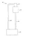
図1は、ループ型ヒートパイプの一例を表した平面図である。 FIG. 1 is a plan view showing an example of a loop heat pipe.
図1に例示したループ型ヒートパイプ10は、補助チャンバ11と、蒸発器12と、凝縮器14と、蒸発器12と凝縮器14との間を連絡する蒸気管13と、凝縮器14と補助チャンバ11との間を連絡する液管15とを有している。また、ループ型ヒートパイプ10内には、水、メタノール又はエタノール等の作動流体が封入されている。 A
補助チャンバ11は蒸発器12に隣接して配置されている。この補助チャンバ11には液相の作動流体が一時的に貯留され、補助チャンバ11から蒸発器12に液相の作動流体が供給される。 The auxiliary chamber 11 is disposed adjacent to the
蒸発器12は、CPU等のように稼動にともなって発熱する電子部品(発熱体)に熱的に接続される。電子部品から蒸発器12に熱が伝達されると、蒸発器12内で作動流体が蒸発して気相に変化する。作動流体が液相から気相に変化するときには、周囲から蒸発熱に相当する熱を吸収する。これにより、蒸発器12が冷却され、更に蒸発器12に熱的に接続された電子部品が冷却される。 The
蒸発器12で気相に変化した作動流体は、蒸気管13を通って凝縮器14に移動する。凝縮器14には例えば放熱フィンや冷却ファンが設けられており、凝縮器14に到達した気相の作動流体は放熱フィンや冷却ファンにより冷却されて液相に戻る。そして、液相に戻った作動流体は、液管15を通って補助チャンバ11に移動する。 The working fluid changed into a gas phase by the
図2(a),(b)は蒸発器12の断面図である。図2(a)は図1のI−I線による断面を表し、図2(b)は図2(a)のII−II線の位置における断面を表している。 2A and 2B are sectional views of the
蒸発器12は、受熱部21と、ほぼ台形の断面を有し受熱部21と一体的に形成された伝熱ブロック22と、多孔質体により形成された円柱状のウィック23とを有し、受熱部21が電子部品に熱的に接続される。 The
伝熱ブロック22にはウィック23を配置する円柱状の空間が設けられている。ウィック23の中心部には補助チャンバ11に連絡する空洞が設けられており、外面には中心軸と平行な方向に延びて蒸気管13に連絡する複数のグルーブ(蒸気排出溝)24が設けられている。 The
補助チャンバ11からウィック23の中心部の空洞に液相の作動流体が流入すると、作動流体はウィック23内に浸透し、毛細管現象によって中心部から外周部側に移動する。そして、ウィック23の外周部に移動した作動流体は、電子部品から受熱部21及び伝熱ブロック22を介して伝達された熱により蒸発して気相に変化する。 When the liquid-phase working fluid flows from the auxiliary chamber 11 into the central cavity of the
ところで、近年、電子機器の小型化及び高性能化が促進されている。それにともなって、電子部品の小型化及び薄型化とともに、ループ型ヒートパイプの小型化及び薄型化が要求されている。しかし、図1のループ型ヒートパイプ10では円柱状のウィック23を使用しており、薄型化には限界がある。 Incidentally, in recent years, downsizing and higher performance of electronic devices have been promoted. Along with this, there is a demand for downsizing and thinning of loop type heat pipes as well as downsizing and thinning of electronic components. However, the
(実施形態)
図3は、実施形態に係るループ型ヒートパイプの平面図である。(Embodiment)
FIG. 3 is a plan view of the loop heat pipe according to the embodiment.
この図3のように、本実施形態に係るループ型ヒートパイプ30は、補助チャンバ31と、蒸発器32と、凝縮器34と、蒸発器32と凝縮器34との間を連絡する蒸気管33と、凝縮器34と補助チャンバ31との間を連絡する液管35とを有している。また、ループ型ヒートパイプ30内には、水、メタノール又はエタノール等の作動流体が封入されている。 As shown in FIG. 3, the
図4は、蒸発器32の断面図である。この図4のように、蒸発器32は、受熱部41と、ハウジング部42と、平板状のウィック43とを有する。 FIG. 4 is a cross-sectional view of the
受熱部41は、銅又はアルミニウム等のように熱伝導性が良好な金属により形成された平板状の部材であり、CPU等の電子部品(発熱体)に熱的に接続される。 The
ハウジング部42は受熱部41に接合されて、受熱部41との間に作動流体が通る空間を形成する。なお、ハウジング部42の材料は特に限定されるものではないが、例えば銅、アルミニウム又はステンレス等の金属により形成すればよい。 The
ウィック43はその縁部の上側及び下側に配置された支持部材44により支持されて、受熱部41とハウジング部42とにより形成される空間内に配置されている。この平板状のウィック43により、受熱部41とハウジング部42とにより形成される空間が、上側の作動液流路45aと下側の蒸気流路45bとに分割されている。作動液流路45aは作動流体入口部42aを介して補助チャンバ31に連絡しており、蒸気流路45bは作動流体出口部42bを介して蒸気管33に連絡している。 The
図5(a)はウィック43の模式的平面図、図5(b)は同じくそのウィック43の模式的断面図である。図5(b)は、図5(a)のIII−III線による断面を表している。 5A is a schematic plan view of the
この図5(a),(b)のように、ウィック43は、作動液流路45a側の面から蒸気流路45b側の面に貫通する多数の細孔46aを有する薄板状の支持体46と、細孔46a内に充填された多孔質構造体47とを有する。多孔質構造体47は球状の空孔が3次元方向につながった構造を有し、骨格部はシリカにより形成されている。 As shown in FIGS. 5A and 5B, the
以下、本実施形態に係るループ型ヒートパイプ30の動作について説明する。ここでは、蒸発器32の受熱部41にCPU等の電子部品(発熱体)が熱的に接続されているものとする。 Hereinafter, the operation of the
補助チャンバ31に貯留された液相の作動流体は、作動流体入口部42aを介して蒸発器32の作動液流路45a内に流入する。そして、作動液流路45a内に流入した作動流体は、ウィック43の多孔質構造体47の空孔内に浸透し、毛細管現象によりウィック43の厚み方向に移動する。 The liquid-phase working fluid stored in the
ウィック43の蒸気流路45b側に移動した作動流体は、電子部品から受熱部41を介して伝達された熱により蒸発して、気相に変化する。作動流体が液相から気相に変化するときには、周囲から蒸発熱に相当する熱を吸収する。これにより、受熱部41が冷却され、更に受熱部41に熱的に接続された電子部品が冷却される。 The working fluid that has moved to the
また、作動流体が液相から気相に変化するときには体積が膨張するため、ウィック43の蒸気流路45b側では圧力が高くなる。このとき、ウィック43(多孔質構造体47)内は液相の作動流体で満たされているため、気相となった作動流体はウィック43内を通ることができず、作動流体出口部42bから蒸気管33を通って凝縮器34に移動する。 Further, since the volume expands when the working fluid changes from the liquid phase to the gas phase, the pressure increases on the
凝縮器34に到達した作動流体は、放熱用フィン及び送風ファン等により冷却されて液相に戻る。そして、液相に戻った作動流体は、蒸気管33を通る気体の圧力により凝縮器34から押し出され、液管34を通って補助チャンバ31に移動する。 The working fluid that has reached the
このようにして、ループ型ヒートパイプ30内の作動流体は、気相と液相とに相変化しながら、補助チャンバ31、蒸発器32、蒸気管33、凝縮器34、液管35の順に移動する。そして、作動流体の移動にともなって、蒸発器32の受熱部41に熱的に接続された電子部品が冷却される。 In this way, the working fluid in the
以下、ウィック43の製造方法の一例について説明する。 Hereinafter, an example of a manufacturing method of the
まず、粒径がほぼ均一のシリカ粒子と、粒径がほぼ均一のポリスチレン粒子とを用意する。 First, silica particles having a substantially uniform particle size and polystyrene particles having a substantially uniform particle size are prepared.
本実施形態では、後述するようにポリスチレン粒子を鋳型としたレプリカ法により多孔質構造体47を作製するため、多孔質構造体47の空孔の大きさはポリスチレン粒子の粒径により決まる。この場合、ポリスチレン粒子の粒径が200nmよりも小さいと、多孔質構造体47の空孔が小さくなりすぎて、多孔質構造体47内を作動流体が移動するときの抵抗が大きくなる。一方、ポリスチレン粒子の粒径が600nmを超えると、多孔質構造体47の毛細管力が小さくなって、作動流体が移動しにくくなる。従って、ポリスチレン粒子の粒径は200nm〜600nmとすることが好ましい。 In this embodiment, since the
一方、シリカ粒子は多孔質構造体47の骨格材料となる。シリカ粒子の粒径は特に限定されるものではないが、後述するようにポリスチレン粒子の間にシリカ粒子のコロイド結晶を形成するためには、3nm〜90nmとすることが好ましい。本実施形態では、ポリスチレン粒子の粒径が500nm、シリカ粒子の粒径が70nmであるとする。 On the other hand, the silica particles become a skeleton material of the
次に、シリカ粒子を水又はアルコール等の分散媒(液体)に混合してコロイド懸濁液とする。そして、このコロイド懸濁液にポリスチレン粒子を混合する。ここでは、分散媒として水を使用し、シリカ粒子とポリスチレン粒子との体積比が1:4となるように混合するものとする。 Next, the silica particles are mixed with a dispersion medium (liquid) such as water or alcohol to obtain a colloidal suspension. Then, polystyrene particles are mixed into this colloidal suspension. Here, water is used as a dispersion medium, and mixing is performed so that the volume ratio of silica particles to polystyrene particles is 1: 4.
この場合、シリカ粒子の密度が2.0g/cm3、ポリスチレン粒子の密度が1.0g/cm3とし、シリカ粒子とポリスチレン粒子と水との体積分率が0.5:2.0:97.5とすると、重量分率は1(シリカ):2(ポリスチレン):97(水)となる。In this case, the density of silica particles is 2.0 g / cm3 , the density of polystyrene particles is 1.0 g / cm3 , and the volume fraction of silica particles, polystyrene particles, and water is 0.5: 2.0: 97. .5, the weight fraction is 1 (silica): 2 (polystyrene): 97 (water).
つまり、この場合は、懸濁液中のシリカ濃度は1wt%となる。懸濁液中のシリカ濃度が0.01wt%未満の場合は、ポリスチレン粒子間の隙間に充填するシリカ粒子の量が少なくなり、多孔質構造体47の骨格強度が低くなる。また、懸濁液中のシリカ濃度が50wt%を超えると、懸濁液の粘度が高くなってポリスチレン粒子間の隙間にシリカ粒子が十分に充填されなくなる。このため、懸濁液中のシリカ濃度は0.01wt%〜50wt%の範囲内とすることが好ましい。 That is, in this case, the silica concentration in the suspension is 1 wt%. When the silica concentration in the suspension is less than 0.01 wt%, the amount of silica particles filled in the gaps between the polystyrene particles decreases, and the skeleton strength of the
次に、細孔が設けられた支持体46を用意する。支持体46としては、ガラス板、セラミック板、フッ素樹脂若しくはポリカーボネート等の樹脂により形成された樹脂フィルム、又は銅、アルミニウム若しくはステンレス等の金属により形成された金属板を使用することができる。支持体46の厚みが薄すぎると十分な強度を確保することができず、支持体46の厚みが厚すぎると蒸発器32を薄型化することができなくなる。このため、支持体46の厚みは、5μm〜1mm程度とすることが好ましい。 Next, a
また、細孔の直径が小さすぎると細孔内に充填できる多孔質構造体47の量が少なくなり、作動流体が移動しにくくなる。一方、細孔の直径が大きすぎると細孔内に多孔質体47を保持しにくくなり、強度が低下する。このため、細孔の直径は0.5μm〜10μm程度とすることが好ましい。 On the other hand, if the pore diameter is too small, the amount of the
ここでは、支持体46として、ポリカーボネートタイプメンブレンフィルタK800A(アドバンテック東洋株式会社販売)を使用するものとする。このメンブレンフィルタの厚みは7μm、細孔の直径は8μm、孔の面密度は1×10⁵個/cm2である。Here, it is assumed that a polycarbonate type membrane filter K800A (available from Advantech Toyo Co., Ltd.) is used as the
なお、支持体46として、図5のように上から下に貫通する細孔46aが設けられた部材に限らず、スポンジ状の空孔を有する部材を使用してもよい。このような部材として、例えば親水性PTFE(polytetrafluoroethylene)タイプメンブレンフィルタH100A(アドバンテック東洋株式会社販売)などがある。 The
また、ここでは支持体46として市販のメンブレンフィルタを使用しているが、市販のメンブレンフィルタによらず、板状の部材に細孔を形成して支持体としてもよいことは勿論である。 Although a commercially available membrane filter is used as the
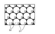
次に、支持体46の上に前述した懸濁液を滴下し、分散媒(水)を蒸発させて支持体46の細孔46a内にポリスチレン粒子とシリカ粒子とを充填する。このとき、分散媒の蒸発にともなってポリスチレン粒子間に横毛管力がはたらき、ポリスチレン粒子が自己集積して面心立方最密充填構造を形成する。すなわち、ポリスチレン粒子がその近傍のポリスチレン粒子と相互に接触する。これと同様に、分散媒の蒸発にともなってシリカ粒子間にも横毛管力がはたらき、ポリスチレン粒子間のスペースに最密充填構造のシリカ粒子が充填される。 Next, the above-described suspension is dropped onto the
図6は、面心最密充填構造を形成したポリスチレン粒子52と、そのポリスチレン粒子52間に充填されたシリカ粒子51とを模式的に表した図である。ポリスチレン粒子52が面心立方最密構造を形成する場合、体積分率の約74%をポリスチレン粒子52が占め、約26%をシリカ粒子51が占めることになる。 FIG. 6 is a diagram schematically showing
次に、支持体46の細孔46a内に充填された懸濁液を乾燥させて固化する。固化の方法は特に限定されないが、例えば減圧乾燥、加熱乾燥、冷凍乾燥、伝導乾燥、赤外線乾燥、マイクロ波乾燥又は超音波乾燥などの方法を用いることができる。 Next, the suspension filled in the
なお、支持体46の細孔46a中に充填するポリスチレン粒子及びシリカ粒子の総量に対するポリスチレン粒子の重量分率は、0.01wt%〜90wt%とすることが好ましい。ポリスチレン粒子の重量分率を上記の範囲内とすることにより、ポリスチレン粒子は3次元周期性が優れた最密充填構造を形成する。ポリスチレン粒子及びシリカ粒子の総量に対するポリスチレン粒子の重量分率のより好ましい範囲は、0.1wt%〜50wt%である。 In addition, it is preferable that the weight fraction of the polystyrene particle with respect to the total amount of the polystyrene particle and silica particle with which it fills in the
次いで、支持体46を例えばトルエン、アセトン又はテトラヒドロフラン等の有機溶剤に浸漬して、ポリスチレン粒子を溶解除去する。これにより、図7のようにポリスチレン粒子が配置されていた部分に球状の空孔53が形成され、球状の空孔53が3次元方向に配列したいわゆる逆オパール構造の多孔質構造体47が得られる。このようにして、ウィック43の製造が完了する。 Next, the
本実施形態においては、上述したように薄板状のウィック43を使用している。これにより、図2に示す円柱状のウィック23を使用した蒸発器22に比べて薄型化することができる。 In the present embodiment, as described above, the thin plate-
また、本実施形態では、多孔質構造体47を支持体46の細孔46a内に充填している。そして、多孔質構造体47は、ポリスチレン粒子に対応する大きさの微細な空孔が連続した構造を有している。これにより、強い毛細管力を得ることができる。 In the present embodiment, the
更に、本実施形態では多孔質構造体47が支持体46に保持されているため、多孔質構造体のみでウィックを形成した場合に比べてウィック43の強度が著しく向上する。このため、前述したようにウィック44を5μm〜1mm程度に薄くしても、十分な強度を確保することができる。 Furthermore, in this embodiment, since the
更にまた、本実施形態では、多孔質構造体47の空孔が球形を連続した形状となるので、作動流体と多孔質構造体47との接触面積が大きい。これにより、作動流体に熱を効率よく伝達することができ、作動流体を効率よく蒸発(気化)させることができる。その結果、熱移送能力が向上する。 Furthermore, in this embodiment, since the pores of the
更にまた、本実施形態ではウィック43の支持体46として熱伝導性が比較的小さい樹脂を使用している。このため、ウィック43から補助チャンバ31への熱リークが抑制でき、蒸発器32内で作動流体をより一層効率的に蒸発させることができる。 Furthermore, in this embodiment, a resin having a relatively low thermal conductivity is used as the
なお、上述の実施形態ではシリカ粒子を用いて多孔質構造体47の骨格を形成しているが、これにより多孔質構造体47の骨格材料がシリカ粒子に限定されるものではない。例えば、多孔質構造体47の骨格材料として、チタニア(酸化チタン)やジルコニア等の微粒子を用いてもよい。 In the above-described embodiment, the skeleton of the
また、本実施形態では多孔質構造体47の空孔を形成するためにポリスチレン粒子を用いているが、ポリスチレン粒子に替えて、PMMA(ポリ(メタ)アクリル酸メチル)、ポリメタクリル酸エステル、ポリ−4−メチルペンテン−1、ポリベンジル(メタ)アクリレート、ポリフェニレンメタクリレート、ポリシクロヘキシル(メタ)アクリレート、ポリエチレンテレフタレート、スチレン・アクリロニトリル共重合体、ポリ塩化ビニル、ポリ塩化ビニリデン、ポリ酢酸ビニル、ポリビニルアルコール、又はポリウレタン等の樹脂の粒子を用いてもよい。 In this embodiment, polystyrene particles are used to form the pores of the
更に、上述の実施形態ではポリスチレン粒子を有機溶剤に溶解させて空孔を形成しているが、支持体46としてセラミック板等の耐熱性を有する部材を使用した場合は、高温で熱処理してポリスチレン粒子を消失させて空孔を形成してもよい。 Furthermore, in the above embodiment, polystyrene particles are dissolved in an organic solvent to form pores. However, when a heat-resistant member such as a ceramic plate is used as the
(電子機器)
図8は、上述の実施形態に係るループ型ヒートパイプ30を実装した電子機器の一例を表した図である。なお、ここでは電子機器がコンピュータの場合について説明しているが、コンピュータ以外の電子機器にループ型ヒートパイプ30を使用してもよいことは勿論である。(Electronics)
FIG. 8 is a diagram illustrating an example of an electronic device in which the
コンピュータ60は、CPU65が実装された配線基板61と、筺体内に冷風を取り入れるための冷却ファン62と、ハードディスクドライブ(記憶装置)63と、電源部64とを有している。 The
ループ型ヒートパイプ30は、その蒸発器32がCPU65の上に配置され、凝縮器34が冷却ファン62の近傍に配置されている。蒸発器32は、図4のように、受熱部41と、ハウジング部42と、平板状のウィック43とを有している。 In the
本実施形態に係る電子機器(コンピュータ60)は、上述した構造のループ型ヒートパイプ30を搭載しているので、CPU65を効率よく冷却することができる。また、ループ型ヒートパイプ30の蒸発器32の厚みが薄い分、電子機器を小型化(薄型化)することができる。 Since the electronic device (computer 60) according to the present embodiment includes the
以上説明した各実施形態に関し、更に以下の付記を開示する。 The following additional notes are disclosed for each embodiment described above.
(付記1)ウィックが配置された内部空間を有する蒸発器と、
凝縮器と、
前記蒸発器と前記凝縮器との間に配置されて気相の作動流体が通る蒸気管と、
前記凝縮器と前記蒸発器との間に配置されて液相の作動流体が通る液管とを有し、
前記ウィックは、
一方の面側から他方の面側に貫通する複数の孔が設けられた板状の支持体と、前記支持体の前記孔内に充填された多孔質構造体とを有することを特徴とするループ型ヒートパイプ。(Appendix 1) an evaporator having an internal space in which a wick is disposed;
A condenser,
A vapor pipe disposed between the evaporator and the condenser and through which a gas-phase working fluid passes;
A liquid pipe disposed between the condenser and the evaporator and through which a liquid-phase working fluid passes,
The wick is
A loop comprising: a plate-like support body provided with a plurality of holes penetrating from one surface side to the other surface side; and a porous structure filled in the holes of the support body Type heat pipe.
(付記2)前記蒸発器の内部空間は、前記ウィックにより、前記液相の作動流体が流入する作動液流路と前記気相の作動流体が通流する蒸気流路とに分割され、前記蒸気流路側には発熱体に熱的に接続される受熱部が設けられていることを特徴とする付記1に記載のループ型ヒートパイプ。 (Supplementary note 2) The internal space of the evaporator is divided by the wick into a working liquid flow path through which the liquid-phase working fluid flows and a vapor flow path through which the gas-phase working fluid flows. The loop-type heat pipe according to appendix 1, wherein a heat receiving portion that is thermally connected to the heating element is provided on the flow path side.
(付記3)前記多孔質構造体は、前記ウィックの一方の面側から他方の面側まで連なった複数の球状の空孔を有することを特徴とする付記1又は2に記載のループ型ヒートパイプ。 (Supplementary Note 3) The loop heat pipe according to Supplementary Note 1 or 2, wherein the porous structure has a plurality of spherical holes continuous from one surface side to the other surface side of the wick. .
(付記4)前記支持体が、樹脂、金属及びセラミックのいずれかにより形成されていることを特徴とする付記1乃至3のいずれか1項に記載のループ型ヒートパイプ。 (Appendix 4) The loop heat pipe according to any one of appendices 1 to 3, wherein the support is formed of any one of resin, metal, and ceramic.
(付記5)前記多孔質構造体の骨格部が、シリカ、チタニア及びジルコニアのうちのいずれかにより形成されていることを特徴とする付記1乃至4のいずれか1項に記載のループ型ヒートパイプ。 (Supplementary note 5) The loop heat pipe according to any one of supplementary notes 1 to 4, wherein the skeleton of the porous structure is formed of any one of silica, titania and zirconia. .
(付記6)板状のウィックを備えたループ型ヒートパイプの製造方法であって、
第1の粒子と、前記第1の粒子と粒径及び材質が異なる球状の第2の粒子とを分散媒に分散させて混合液とする工程と、
一方の面側から他方の面側に貫通する複数の孔が設けられた板状の支持体を用意し、該支持体の前記孔内に前記混合液を浸入させる工程と、
前記混合液を蒸発させて前記支持体の前記孔内に前記第1の粒子と前記第2の粒子とを残留させる工程と、
前記第2の粒子を除去して前記支持体の前記孔内に多孔質構造体を形成する工程と、
を実施して前記ウィックを形成することを特徴とするループ型ヒートパイプの製造方法。(Appendix 6) A method for producing a loop heat pipe having a plate-like wick,
A step of dispersing first particles and second spherical particles having different particle sizes and materials from the first particles in a dispersion medium to obtain a mixed solution;
Preparing a plate-like support provided with a plurality of holes penetrating from one surface side to the other surface side, and allowing the mixed liquid to enter the holes of the support; and
Evaporating the mixture to leave the first particles and the second particles in the holes of the support;
Removing the second particles to form a porous structure in the pores of the support;
And forming the wick to form a loop heat pipe.
(付記7)前記第1の粒子が、シリカ粒子、チタニア粒子及びジルコニア粒子のいずれかであることを特徴とする付記6に記載のループ型ヒートパイプの製造方法。 (Additional remark 7) The said 1st particle | grain is any one of a silica particle, a titania particle, and a zirconia particle, The manufacturing method of the loop type heat pipe of Additional remark 6 characterized by the above-mentioned.
(付記8)前記第2の粒子が、溶剤に溶解可能な樹脂により形成されていることを特徴とする付記6又は7に記載のループ型ヒートパイプの製造方法。 (Additional remark 8) The said 2nd particle is formed with resin which can be melt | dissolved in a solvent, The manufacturing method of the loop type heat pipe of Additional remark 6 or 7 characterized by the above-mentioned.
(付記9)前記第1の粒子の粒径が3nm乃至90nmであり、前記第2の粒子の粒径が200nm乃至600nmであることを特徴とする付記6乃至8のいずれか1項に記載のループ型ヒートパイプの製造方法。 (Additional remark 9) The particle diameter of the said 1st particle is 3 nm thru | or 90 nm, The particle diameter of the said 2nd particle is 200 nm thru | or 600 nm, It is any one of Additional remark 6 thru | or 8 characterized by the above-mentioned. A method of manufacturing a loop heat pipe.
(付記10)電子部品と、
ウィックが配置された内部空間を有し、前記電子部品に熱的に接続された蒸発器を備えたループ型ヒートパイプとを有し、
前記ウィックは、
一方の面側から他方の面側に貫通する複数の孔が設けられた板状の支持体と、前記支持体の前記孔内に充填された多孔質構造体とを有することを特徴とする電子機器。(Appendix 10) Electronic components;
A loop heat pipe having an internal space in which a wick is disposed and having an evaporator thermally connected to the electronic component;
The wick is
An electron comprising: a plate-like support body provided with a plurality of holes penetrating from one surface side to the other surface side; and a porous structure filled in the holes of the support body machine.
10…ループ型ヒートパイプ、11…補助チャンバ、12…蒸発器、13…蒸気管、14…凝縮器、15…液管、21…受熱部、22…伝熱ブロック、23…ウィック、24…グルーブ、30…ループ型ヒートパイプ、31…補助チャンバ、32…蒸発器、33…蒸気管、34…凝縮器、35…液管、41…受熱部、42…ハウジング部、43…ウィック、44…支持部材、45a…作動液流路、45b…蒸気流路、46…支持体、46a…細孔、47…多孔質構造体、51…シリカ粒子、52…ポリスチレン粒子、60…コンピュータ(電子機器)、61…配線基板、62…冷却ファン、63…ハードディスクドライブ、64…電源部、65…CPU(電子部品)。 DESCRIPTION OF
Claims (5)
Translated fromJapanese凝縮器と、
前記蒸発器と前記凝縮器との間に配置されて気相の作動流体が通る蒸気管と、
前記凝縮器と前記蒸発器との間に配置されて液相の作動流体が通る液管とを有し、
前記ウイックは、
一方の面側から他方の面側に貫通する複数の孔が設けられた板状の樹脂又はセラミック製の支持体と、前記支持体の前記孔内に充填された多孔質構造体とを有することを特徴とするループ型ヒートパイプ。An evaporator having an internal space in which the wick is disposed;
A condenser,
A vapor pipe disposed between the evaporator and the condenser and through which a gas-phase working fluid passes;
A liquid pipe disposed between the condenser and the evaporator and through which a liquid-phase working fluid passes,
The wick is
It has a plate-likeresin or ceramic support provided with a plurality of holes penetrating from one surface to the other surface, and a porous structure filled in the holes of the support Loop type heat pipe characterized by
第1の粒子と、前記第1の粒子と粒径及び材質が異なる球状の第2の粒子とを分散媒に分散させて混合液とする工程と、
一方の面側から他方の面側に貫通する複数の孔が設けられた板状の樹脂又はセラミック製の支持体を用意し、該支持体の前記孔内に前記混合液を浸入させる工程と、
前記混合液を蒸発させて前記支持体の前記孔内に前記第1の粒子と前記第2の粒子とを残留させる工程と、
前記第2の粒子を除去して前記支持体の前記孔内に多孔質構造体を形成する工程と、
を実施して前記ウイックを形成することを特徴とするループ型ヒートパイプの製造方法。A method for manufacturing a loop heat pipe with a plate-like wick,
A step of dispersing first particles and second spherical particles having different particle sizes and materials from the first particles in a dispersion medium to obtain a mixed solution;
Preparing a plate-likeresin or ceramic support provided with a plurality of holes penetrating from one surface side to the other surface, and allowing the mixed solution to enter into the holes of the support; and
Evaporating the mixture to leave the first particles and the second particles in the holes of the support;
Removing the second particles to form a porous structure in the pores of the support;
To form the wick, a method for manufacturing a loop heat pipe.
ウイックが配置された内部空間を有し、前記電子部品に熱的に接続された蒸発器を備えたループ型ヒートパイプとを有し、
前記ウイックは、
一方の面側から他方の面側に貫通する複数の孔が設けられた板状の樹脂又はセラミック製の支持体と、前記支持体の前記孔内に充填された多孔質構造体とを有することを特徴とする電子機器。Electronic components,
A loop-type heat pipe having an internal space in which a wick is disposed and having an evaporator thermally connected to the electronic component;
The wick is
It has a plate-likeresin or ceramic support provided with a plurality of holes penetrating from one surface to the other surface, and a porous structure filled in the holes of the support Electronic equipment characterized by
Priority Applications (1)
| Application Number | Priority Date | Filing Date | Title |
|---|---|---|---|
| JP2011101751AJP5765045B2 (en) | 2011-04-28 | 2011-04-28 | Loop heat pipe and manufacturing method thereof |
Applications Claiming Priority (1)
| Application Number | Priority Date | Filing Date | Title |
|---|---|---|---|
| JP2011101751AJP5765045B2 (en) | 2011-04-28 | 2011-04-28 | Loop heat pipe and manufacturing method thereof |
Publications (2)
| Publication Number | Publication Date |
|---|---|
| JP2012233625A JP2012233625A (en) | 2012-11-29 |
| JP5765045B2true JP5765045B2 (en) | 2015-08-19 |
Family
ID=47434106
Family Applications (1)
| Application Number | Title | Priority Date | Filing Date |
|---|---|---|---|
| JP2011101751AExpired - Fee RelatedJP5765045B2 (en) | 2011-04-28 | 2011-04-28 | Loop heat pipe and manufacturing method thereof |
Country Status (1)
| Country | Link |
|---|---|
| JP (1) | JP5765045B2 (en) |
Families Citing this family (8)
| Publication number | Priority date | Publication date | Assignee | Title |
|---|---|---|---|---|
| JP2014120516A (en)* | 2012-12-13 | 2014-06-30 | Fujitsu Ltd | Semiconductor device |
| KR102214978B1 (en)* | 2017-03-24 | 2021-02-10 | 한온시스템 주식회사 | Cooling device for vehicle heating element |
| JP6988170B2 (en)* | 2017-04-28 | 2022-01-05 | 株式会社村田製作所 | Vapor chamber |
| JP7206716B2 (en)* | 2018-09-07 | 2023-01-18 | トヨタ自動車株式会社 | Evaporator, manufacturing method thereof, and loop heat pipe having evaporator |
| JP7284988B2 (en)* | 2018-10-19 | 2023-06-01 | 国立大学法人電気通信大学 | Heat pipe manufacturing method |
| JP6787988B2 (en) | 2018-12-26 | 2020-11-18 | Necプラットフォームズ株式会社 | Cooling device and manufacturing method of cooling device |
| CN113453494B (en)* | 2021-05-18 | 2023-08-15 | 江西新菲新材料有限公司 | Vapor chamber preparation method, vapor chamber and electronic equipment |
| TW202516143A (en)* | 2023-10-06 | 2025-04-16 | 國立大學法人東海國立大學機構 | Heat exchanger, evaporator, heat exchange device and moving body |
Family Cites Families (6)
| Publication number | Priority date | Publication date | Assignee | Title |
|---|---|---|---|---|
| JP2004077051A (en)* | 2002-08-20 | 2004-03-11 | Sony Corp | Heat transport device and its manufacturing method |
| JP2004095684A (en)* | 2002-08-29 | 2004-03-25 | Fujikura Ltd | heatsink |
| JP2005300038A (en)* | 2004-04-13 | 2005-10-27 | Sony Corp | Heat transport device, process for manufacturing the heat transport device and electronic device |
| JP2009109079A (en)* | 2007-10-30 | 2009-05-21 | Asahi Kasei Fibers Corp | Loop heat pipe type heat transfer device |
| JP2010096405A (en)* | 2008-10-16 | 2010-04-30 | Emaus Kyoto:Kk | Heat pipe including wick of monolith type porous body |
| JP2010107153A (en)* | 2008-10-31 | 2010-05-13 | Toshiba Corp | Evaporator and circulation type cooling device using the same |
- 2011
- 2011-04-28JPJP2011101751Apatent/JP5765045B2/ennot_activeExpired - Fee Related
Also Published As
| Publication number | Publication date |
|---|---|
| JP2012233625A (en) | 2012-11-29 |
Similar Documents
| Publication | Publication Date | Title |
|---|---|---|
| JP5765045B2 (en) | Loop heat pipe and manufacturing method thereof | |
| Li et al. | Mechanism of a microscale flat plate heat pipe with extremely high nominal thermal conductivity for cooling high-end smartphone chips | |
| JP3202014B2 (en) | Micro cooling device | |
| US7327572B2 (en) | Heat dissipating device with enhanced boiling/condensation structure | |
| Kandlikar | Mechanistic considerations for enhancing flow boiling heat transfer in microchannels | |
| WO2010050129A1 (en) | Cooling structure, electronic device, and cooling method | |
| Xu et al. | Modulated porous wick evaporator for loop heat pipes: Experiment | |
| Riofrío et al. | State of the art of efficient pumped two-phase flow cooling technologies | |
| TWI846739B (en) | A two-phase cooling system with flow boiling | |
| JP2006503436A (en) | Plate heat transfer device and manufacturing method thereof | |
| US20080043440A1 (en) | Nano-patch thermal management devices, methods, & systems | |
| JP2006513577A (en) | Hybrid cooling device | |
| US20100314093A1 (en) | Variable heat exchanger | |
| JP2010522996A (en) | Thin thermal diffusion liquid chamber using boiling | |
| US20140144609A1 (en) | Evaporator for looped heat pipe system and method of manufacturing the same | |
| Shan et al. | Microchannel-elevated micromembrane for sustainable phase-separation condensation | |
| JP2010107153A (en) | Evaporator and circulation type cooling device using the same | |
| JP2011080679A (en) | Heat transfer device and electronic equipment | |
| Stephan et al. | Advanced capillary structures for high performance heat pipes | |
| Lu et al. | Experimental study on a novel loop heat pipe with both flat evaporator and boiling pool | |
| JP2013245875A (en) | Cooling device and electronic device | |
| JP2007263427A (en) | Loop type heat pipe | |
| Chen et al. | Enhanced boiling heat transfer performance on mini-pin-finned copper surfaces in FC-72 | |
| Kandlikar | Microscale to macroscale—extending microscale enhancement techniques to large-scale boiling equipment | |
| Chen et al. | High power electronic component |
Legal Events
| Date | Code | Title | Description |
|---|---|---|---|
| A621 | Written request for application examination | Free format text:JAPANESE INTERMEDIATE CODE: A621 Effective date:20140204 | |
| A977 | Report on retrieval | Free format text:JAPANESE INTERMEDIATE CODE: A971007 Effective date:20141029 | |
| A131 | Notification of reasons for refusal | Free format text:JAPANESE INTERMEDIATE CODE: A131 Effective date:20141104 | |
| A521 | Written amendment | Free format text:JAPANESE INTERMEDIATE CODE: A523 Effective date:20141215 | |
| TRDD | Decision of grant or rejection written | ||
| A01 | Written decision to grant a patent or to grant a registration (utility model) | Free format text:JAPANESE INTERMEDIATE CODE: A01 Effective date:20150519 | |
| A61 | First payment of annual fees (during grant procedure) | Free format text:JAPANESE INTERMEDIATE CODE: A61 Effective date:20150601 | |
| R150 | Certificate of patent or registration of utility model | Ref document number:5765045 Country of ref document:JP Free format text:JAPANESE INTERMEDIATE CODE: R150 | |
| LAPS | Cancellation because of no payment of annual fees |