JP5764310B2 - Power transmission device - Google Patents
Power transmission deviceDownload PDFInfo
- Publication number
- JP5764310B2 JP5764310B2JP2010241105AJP2010241105AJP5764310B2JP 5764310 B2JP5764310 B2JP 5764310B2JP 2010241105 AJP2010241105 AJP 2010241105AJP 2010241105 AJP2010241105 AJP 2010241105AJP 5764310 B2JP5764310 B2JP 5764310B2
- Authority
- JP
- Japan
- Prior art keywords
- engine
- hydraulic pump
- battery
- main controller
- power
- Prior art date
- Legal status (The legal status is an assumption and is not a legal conclusion. Google has not performed a legal analysis and makes no representation as to the accuracy of the status listed.)
- Expired - Fee Related
Links
Images


Classifications
- B—PERFORMING OPERATIONS; TRANSPORTING
- B60—VEHICLES IN GENERAL
- B60W—CONJOINT CONTROL OF VEHICLE SUB-UNITS OF DIFFERENT TYPE OR DIFFERENT FUNCTION; CONTROL SYSTEMS SPECIALLY ADAPTED FOR HYBRID VEHICLES; ROAD VEHICLE DRIVE CONTROL SYSTEMS FOR PURPOSES NOT RELATED TO THE CONTROL OF A PARTICULAR SUB-UNIT
- B60W20/00—Control systems specially adapted for hybrid vehicles
- B60W20/40—Controlling the engagement or disengagement of prime movers, e.g. for transition between prime movers
- B—PERFORMING OPERATIONS; TRANSPORTING
- B60—VEHICLES IN GENERAL
- B60W—CONJOINT CONTROL OF VEHICLE SUB-UNITS OF DIFFERENT TYPE OR DIFFERENT FUNCTION; CONTROL SYSTEMS SPECIALLY ADAPTED FOR HYBRID VEHICLES; ROAD VEHICLE DRIVE CONTROL SYSTEMS FOR PURPOSES NOT RELATED TO THE CONTROL OF A PARTICULAR SUB-UNIT
- B60W10/00—Conjoint control of vehicle sub-units of different type or different function
- B60W10/02—Conjoint control of vehicle sub-units of different type or different function including control of driveline clutches
- B—PERFORMING OPERATIONS; TRANSPORTING
- B60—VEHICLES IN GENERAL
- B60W—CONJOINT CONTROL OF VEHICLE SUB-UNITS OF DIFFERENT TYPE OR DIFFERENT FUNCTION; CONTROL SYSTEMS SPECIALLY ADAPTED FOR HYBRID VEHICLES; ROAD VEHICLE DRIVE CONTROL SYSTEMS FOR PURPOSES NOT RELATED TO THE CONTROL OF A PARTICULAR SUB-UNIT
- B60W10/00—Conjoint control of vehicle sub-units of different type or different function
- B60W10/04—Conjoint control of vehicle sub-units of different type or different function including control of propulsion units
- B60W10/06—Conjoint control of vehicle sub-units of different type or different function including control of propulsion units including control of combustion engines
- B—PERFORMING OPERATIONS; TRANSPORTING
- B60—VEHICLES IN GENERAL
- B60W—CONJOINT CONTROL OF VEHICLE SUB-UNITS OF DIFFERENT TYPE OR DIFFERENT FUNCTION; CONTROL SYSTEMS SPECIALLY ADAPTED FOR HYBRID VEHICLES; ROAD VEHICLE DRIVE CONTROL SYSTEMS FOR PURPOSES NOT RELATED TO THE CONTROL OF A PARTICULAR SUB-UNIT
- B60W10/00—Conjoint control of vehicle sub-units of different type or different function
- B60W10/04—Conjoint control of vehicle sub-units of different type or different function including control of propulsion units
- B60W10/08—Conjoint control of vehicle sub-units of different type or different function including control of propulsion units including control of electric propulsion units, e.g. motors or generators
- B—PERFORMING OPERATIONS; TRANSPORTING
- B60—VEHICLES IN GENERAL
- B60W—CONJOINT CONTROL OF VEHICLE SUB-UNITS OF DIFFERENT TYPE OR DIFFERENT FUNCTION; CONTROL SYSTEMS SPECIALLY ADAPTED FOR HYBRID VEHICLES; ROAD VEHICLE DRIVE CONTROL SYSTEMS FOR PURPOSES NOT RELATED TO THE CONTROL OF A PARTICULAR SUB-UNIT
- B60W10/00—Conjoint control of vehicle sub-units of different type or different function
- B60W10/24—Conjoint control of vehicle sub-units of different type or different function including control of energy storage means
- B60W10/26—Conjoint control of vehicle sub-units of different type or different function including control of energy storage means for electrical energy, e.g. batteries or capacitors
- B—PERFORMING OPERATIONS; TRANSPORTING
- B60—VEHICLES IN GENERAL
- B60W—CONJOINT CONTROL OF VEHICLE SUB-UNITS OF DIFFERENT TYPE OR DIFFERENT FUNCTION; CONTROL SYSTEMS SPECIALLY ADAPTED FOR HYBRID VEHICLES; ROAD VEHICLE DRIVE CONTROL SYSTEMS FOR PURPOSES NOT RELATED TO THE CONTROL OF A PARTICULAR SUB-UNIT
- B60W20/00—Control systems specially adapted for hybrid vehicles
- B60W20/10—Controlling the power contribution of each of the prime movers to meet required power demand
- B60W20/11—Controlling the power contribution of each of the prime movers to meet required power demand using model predictive control [MPC] strategies, i.e. control methods based on models predicting performance
- B—PERFORMING OPERATIONS; TRANSPORTING
- B60—VEHICLES IN GENERAL
- B60W—CONJOINT CONTROL OF VEHICLE SUB-UNITS OF DIFFERENT TYPE OR DIFFERENT FUNCTION; CONTROL SYSTEMS SPECIALLY ADAPTED FOR HYBRID VEHICLES; ROAD VEHICLE DRIVE CONTROL SYSTEMS FOR PURPOSES NOT RELATED TO THE CONTROL OF A PARTICULAR SUB-UNIT
- B60W20/00—Control systems specially adapted for hybrid vehicles
- B60W20/20—Control strategies involving selection of hybrid configuration, e.g. selection between series or parallel configuration
- E—FIXED CONSTRUCTIONS
- E02—HYDRAULIC ENGINEERING; FOUNDATIONS; SOIL SHIFTING
- E02F—DREDGING; SOIL-SHIFTING
- E02F9/00—Component parts of dredgers or soil-shifting machines, not restricted to one of the kinds covered by groups E02F3/00 - E02F7/00
- E02F9/20—Drives; Control devices
- E02F9/2058—Electric or electro-mechanical or mechanical control devices of vehicle sub-units
- E02F9/2062—Control of propulsion units
- E02F9/2075—Control of propulsion units of the hybrid type
- E—FIXED CONSTRUCTIONS
- E02—HYDRAULIC ENGINEERING; FOUNDATIONS; SOIL SHIFTING
- E02F—DREDGING; SOIL-SHIFTING
- E02F9/00—Component parts of dredgers or soil-shifting machines, not restricted to one of the kinds covered by groups E02F3/00 - E02F7/00
- E02F9/20—Drives; Control devices
- E02F9/2058—Electric or electro-mechanical or mechanical control devices of vehicle sub-units
- E02F9/2079—Control of mechanical transmission
- E—FIXED CONSTRUCTIONS
- E02—HYDRAULIC ENGINEERING; FOUNDATIONS; SOIL SHIFTING
- E02F—DREDGING; SOIL-SHIFTING
- E02F9/00—Component parts of dredgers or soil-shifting machines, not restricted to one of the kinds covered by groups E02F3/00 - E02F7/00
- E02F9/20—Drives; Control devices
- E02F9/22—Hydraulic or pneumatic drives
- E02F9/2246—Control of prime movers, e.g. depending on the hydraulic load of work tools
- E—FIXED CONSTRUCTIONS
- E02—HYDRAULIC ENGINEERING; FOUNDATIONS; SOIL SHIFTING
- E02F—DREDGING; SOIL-SHIFTING
- E02F9/00—Component parts of dredgers or soil-shifting machines, not restricted to one of the kinds covered by groups E02F3/00 - E02F7/00
- E02F9/20—Drives; Control devices
- E02F9/22—Hydraulic or pneumatic drives
- E02F9/2278—Hydraulic circuits
- E02F9/2292—Systems with two or more pumps
- E—FIXED CONSTRUCTIONS
- E02—HYDRAULIC ENGINEERING; FOUNDATIONS; SOIL SHIFTING
- E02F—DREDGING; SOIL-SHIFTING
- E02F9/00—Component parts of dredgers or soil-shifting machines, not restricted to one of the kinds covered by groups E02F3/00 - E02F7/00
- E02F9/20—Drives; Control devices
- E02F9/22—Hydraulic or pneumatic drives
- E02F9/2278—Hydraulic circuits
- E02F9/2296—Systems with a variable displacement pump
- F—MECHANICAL ENGINEERING; LIGHTING; HEATING; WEAPONS; BLASTING
- F02—COMBUSTION ENGINES; HOT-GAS OR COMBUSTION-PRODUCT ENGINE PLANTS
- F02D—CONTROLLING COMBUSTION ENGINES
- F02D29/00—Controlling engines, such controlling being peculiar to the devices driven thereby, the devices being other than parts or accessories essential to engine operation, e.g. controlling of engines by signals external thereto
- F02D29/02—Controlling engines, such controlling being peculiar to the devices driven thereby, the devices being other than parts or accessories essential to engine operation, e.g. controlling of engines by signals external thereto peculiar to engines driving vehicles; peculiar to engines driving variable pitch propellers
- F—MECHANICAL ENGINEERING; LIGHTING; HEATING; WEAPONS; BLASTING
- F02—COMBUSTION ENGINES; HOT-GAS OR COMBUSTION-PRODUCT ENGINE PLANTS
- F02D—CONTROLLING COMBUSTION ENGINES
- F02D29/00—Controlling engines, such controlling being peculiar to the devices driven thereby, the devices being other than parts or accessories essential to engine operation, e.g. controlling of engines by signals external thereto
- F02D29/04—Controlling engines, such controlling being peculiar to the devices driven thereby, the devices being other than parts or accessories essential to engine operation, e.g. controlling of engines by signals external thereto peculiar to engines driving pumps
- B—PERFORMING OPERATIONS; TRANSPORTING
- B60—VEHICLES IN GENERAL
- B60W—CONJOINT CONTROL OF VEHICLE SUB-UNITS OF DIFFERENT TYPE OR DIFFERENT FUNCTION; CONTROL SYSTEMS SPECIALLY ADAPTED FOR HYBRID VEHICLES; ROAD VEHICLE DRIVE CONTROL SYSTEMS FOR PURPOSES NOT RELATED TO THE CONTROL OF A PARTICULAR SUB-UNIT
- B60W2300/00—Indexing codes relating to the type of vehicle
- B60W2300/17—Construction vehicles, e.g. graders, excavators
- B—PERFORMING OPERATIONS; TRANSPORTING
- B60—VEHICLES IN GENERAL
- B60W—CONJOINT CONTROL OF VEHICLE SUB-UNITS OF DIFFERENT TYPE OR DIFFERENT FUNCTION; CONTROL SYSTEMS SPECIALLY ADAPTED FOR HYBRID VEHICLES; ROAD VEHICLE DRIVE CONTROL SYSTEMS FOR PURPOSES NOT RELATED TO THE CONTROL OF A PARTICULAR SUB-UNIT
- B60W2556/00—Input parameters relating to data
- Y—GENERAL TAGGING OF NEW TECHNOLOGICAL DEVELOPMENTS; GENERAL TAGGING OF CROSS-SECTIONAL TECHNOLOGIES SPANNING OVER SEVERAL SECTIONS OF THE IPC; TECHNICAL SUBJECTS COVERED BY FORMER USPC CROSS-REFERENCE ART COLLECTIONS [XRACs] AND DIGESTS
- Y02—TECHNOLOGIES OR APPLICATIONS FOR MITIGATION OR ADAPTATION AGAINST CLIMATE CHANGE
- Y02T—CLIMATE CHANGE MITIGATION TECHNOLOGIES RELATED TO TRANSPORTATION
- Y02T10/00—Road transport of goods or passengers
- Y02T10/60—Other road transportation technologies with climate change mitigation effect
- Y02T10/62—Hybrid vehicles
- Y—GENERAL TAGGING OF NEW TECHNOLOGICAL DEVELOPMENTS; GENERAL TAGGING OF CROSS-SECTIONAL TECHNOLOGIES SPANNING OVER SEVERAL SECTIONS OF THE IPC; TECHNICAL SUBJECTS COVERED BY FORMER USPC CROSS-REFERENCE ART COLLECTIONS [XRACs] AND DIGESTS
- Y10—TECHNICAL SUBJECTS COVERED BY FORMER USPC
- Y10S—TECHNICAL SUBJECTS COVERED BY FORMER USPC CROSS-REFERENCE ART COLLECTIONS [XRACs] AND DIGESTS
- Y10S903/00—Hybrid electric vehicles, HEVS
- Y10S903/902—Prime movers comprising electrical and internal combustion motors
- Y10S903/903—Prime movers comprising electrical and internal combustion motors having energy storing means, e.g. battery, capacitor
- Y10S903/93—Conjoint control of different elements
Landscapes
- Engineering & Computer Science (AREA)
- Chemical & Material Sciences (AREA)
- Combustion & Propulsion (AREA)
- General Engineering & Computer Science (AREA)
- Mechanical Engineering (AREA)
- Mining & Mineral Resources (AREA)
- Civil Engineering (AREA)
- Structural Engineering (AREA)
- Transportation (AREA)
- Automation & Control Theory (AREA)
- Control Of Vehicle Engines Or Engines For Specific Uses (AREA)
- Operation Control Of Excavators (AREA)
Description
Translated fromJapanese本発明は、エンジン及び電動機を用いた動力伝達装置の技術に関する。 The present invention relates to a technology of a power transmission device using an engine and an electric motor.
従来、所定の場合に自動的にエンジンを停止、又は始動させる動力伝達装置に関する技術は公知となっている。例えば、特許文献1に記載の如くである。 Conventionally, a technique related to a power transmission device that automatically stops or starts an engine in a predetermined case is known. For example, as described in Patent Document 1.
特許文献1に記載の動力伝達装置は、動力源たるエンジンと、作動油を吐出するための油圧ポンプと、エンジンの出力軸と油圧ポンプの入力軸との間に介設されるクラッチと、油圧ポンプの入力軸に連結される電動機(電気モータ)と、電動機の入力軸に固設されるフライホイールと、油圧ポンプから供給される作動油により駆動するアクチュエータと、アクチュエータを操作するための操作手段と、を具備する。アクチュエータに加わる負荷が無負荷に近い場合、クラッチが切断され、エンジンが停止されるとともに、電動機により油圧ポンプが駆動される。また、エンジンが停止された状態において、作業者により操作手段が操作された場合(すなわち、アクチュエータに負荷が加わると予測される場合)、クラッチが接続され、フライホイールの慣性又は電動機の駆動力によりエンジンが再始動される。このように、アクチュエータに負荷が加わらない場合、すなわち作業を行わない場合にはエンジンを停止させることで無駄な燃料消費を無くすとともに、アクチュエータにより作業を開始する際には速やかにエンジンを始動させることができる。 The power transmission device described in Patent Document 1 includes an engine as a power source, a hydraulic pump for discharging hydraulic oil, a clutch interposed between an output shaft of the engine and an input shaft of the hydraulic pump, An electric motor (electric motor) connected to the input shaft of the pump, a flywheel fixed to the input shaft of the electric motor, an actuator driven by hydraulic oil supplied from the hydraulic pump, and an operating means for operating the actuator And. When the load applied to the actuator is close to no load, the clutch is disconnected, the engine is stopped, and the hydraulic pump is driven by the electric motor. Further, when the operating means is operated by the operator with the engine stopped (that is, when it is predicted that a load is applied to the actuator), the clutch is connected, and the inertia of the flywheel or the driving force of the electric motor The engine is restarted. As described above, when no load is applied to the actuator, that is, when the work is not performed, the engine is stopped, so that unnecessary fuel consumption is eliminated, and when the work is started by the actuator, the engine is quickly started. Can do.
しかし、特許文献1に記載の動力伝達装置では、油圧ポンプを駆動するための電動機を、エンジンを始動させるスタータモータとして兼用するため、エンジンを再始動させる際に電動機の回転数が低下する場合がある。この場合、電動機の回転数の低下に伴って油圧ポンプの回転数が低下し、アクチュエータへ供給される作動油の流量が低下する。これによって、当該アクチュエータの動作速度が低下し、作業者によるアクチュエータの操作フィーリングが悪化する点で不利であった。 However, in the power transmission device described in Patent Document 1, since the electric motor for driving the hydraulic pump is also used as a starter motor for starting the engine, the rotation speed of the electric motor may decrease when the engine is restarted. is there. In this case, the rotational speed of the hydraulic pump decreases as the rotational speed of the electric motor decreases, and the flow rate of hydraulic fluid supplied to the actuator decreases. This is disadvantageous in that the operating speed of the actuator is lowered, and the feeling of operating the actuator by the operator is deteriorated.
本発明の目的は、燃料の無駄な消費を抑制するとともに、エンジンの再始動時におけるアクチュエータの操作フィーリングの悪化を防止することが可能な動力伝達装置を提供することである。 The objective of this invention is providing the power transmission device which can prevent the deterioration of the operation feeling of the actuator at the time of restarting an engine while suppressing useless consumption of fuel.
本発明の解決しようとする課題は以上の如くであり、次にこの課題を解決するための手段を説明する。 The problem to be solved by the present invention is as described above. Next, means for solving the problem will be described.
請求項1においては、バッテリと、前記バッテリからの電力の供給により回転駆動される電動機と、エンジンと、前記エンジンを始動するためのセルモータと、前記電動機又は前記エンジンによって駆動される少なくとも1つの油圧ポンプと、前記エンジンから前記油圧ポンプへと伝達される動力を断接するクラッチと、前記バッテリから前記電動機への電力の供給を許可又は遮断する切換手段と、作業用油圧アクチュエータを操作するための操作手段と、前記操作手段が操作されているか否かを検出する操作状態検出手段と、前記エンジンの回転数を検出するエンジン回転数検出手段と、前記油圧ポンプの回転数を検出するポンプ回転数検出手段と、前記操作手段が所定時間以上操作されていないことを検出した場合、前記エンジンを停止し、前記クラッチを切断し、かつ前記バッテリから前記電動機への電力の供給を遮断し、その後前記操作手段が操作されたことを検出した場合、前記セルモータにより前記エンジンを始動し、かつ前記バッテリから前記電動機への電力の供給を許可し、前記エンジンの回転数が所定の値以上になった後に前記クラッチを接続し、かつ前記バッテリから前記電動機への電力の供給を遮断するアイドルストップ制御を行う制御装置とを具備し、前記油圧ポンプの吐出圧を検出する圧力検出手段と、前記油圧ポンプの押しのけ容積を検出する容積検出手段とを具備し、前記制御装置は、前記圧力検出手段、前記容積検出手段、及び前記ポンプ回転数検出手段による検出値に基づいて前記油圧ポンプの吸収馬力を算出し、前記アイドルストップ制御において、前記操作手段が操作されたことを検出した場合であっても、前記吸収馬力が所定値未満であるときは、前記エンジンを始動することなく前記バッテリから前記電動機への電力の供給を許可し、前記吸収馬力が所定値以上になったときは、前記エンジンを始動するものである。2. The battery according to claim 1, a motor that is rotationally driven by the supply of power from the battery, an engine, a cell motor for starting the engine, and at least one hydraulic pressure that is driven by the motor or the engine. A pump, a clutch for connecting / disconnecting power transmitted from the engine to the hydraulic pump, switching means for permitting or interrupting the supply of electric power from the battery to the electric motor, and an operation for operating the hydraulic actuator for work Means, an operation state detecting means for detecting whether or not the operating means is operated, an engine speed detecting means for detecting the rotational speed of the engine, and a pump rotational speed detection for detecting the rotational speed of the hydraulic pump And the engine is stopped when it is detected that the operation means has not been operated for a predetermined time or more. The clutch is disengaged, the supply of electric power from the battery to the electric motor is cut off, and then the operation means is detected, the engine is started by the cell motor, and the battery Control for performing idle stop control that permits supply of electric power to the electric motor, connects the clutch after the engine speed exceeds a predetermined value, and cuts off electric power supply from the battery to the electric motor Anda pressure detecting means for detecting a discharge pressure of the hydraulic pump, and a volume detecting means for detecting a displacement volume of the hydraulic pump, and the control device includes the pressure detecting means and the volume detecting means. And an absorption horsepower of the hydraulic pump based on a detection value by the pump rotation speed detection means, and the idle stop control. Even when it is detected that the operating means has been operated, if the absorption horsepower is less than a predetermined value, the power supply from the battery to the electric motor is permitted without starting the engine. And when the said absorption horsepower becomes more than predetermined value, the said engine is started .
請求項2においては、前記アイドルストップ制御を行うか否かを選択するためのアイドルストップ選択手段を具備し、前記制御装置は、前記アイドルストップ選択手段により前記アイドルストップ制御を行わない選択がされた場合、前記アイドルストップ制御を行わないものである。According to a second aspect of the present invention, there is provided idle stop selection means for selecting whether or not to perform the idle stop control, and the control device is selected not to perform the idle stop control by the idle stop selection means. In this case, the idle stop control is not performed.
本発明の効果として、以下に示すような効果を奏する。 As effects of the present invention, the following effects can be obtained.
請求項1においては、作業用油圧アクチュエータを操作しない場合にはエンジンを停止することで、燃料の無駄な消費を抑制することができる。
エンジンの再始動時には、エンジンの回転数が所定の値以上になるまでは電動機により油圧ポンプを駆動し、所定の値以上になった後にはエンジンで油圧ポンプを駆動する。これによって、エンジンの再始動直後で当該エンジンの回転数が低い場合であっても、油圧ポンプの回転数の低下を防止することができ、ひいては油圧ポンプが吐出する作動油の流量の低下を防止することができる。したがって、エンジンの再始動時における作業用油圧アクチュエータの操作フィーリングの悪化を防止することができる。According to the first aspect of the present invention, when the working hydraulic actuator is not operated, the engine is stopped, so that wasteful fuel consumption can be suppressed.
When the engine is restarted, the hydraulic pump is driven by the electric motor until the rotational speed of the engine becomes a predetermined value or higher, and after the predetermined value or higher, the hydraulic pump is driven by the engine. As a result, even when the engine speed is low immediately after the engine is restarted, it is possible to prevent the hydraulic pump speed from being lowered, and thus to prevent the hydraulic fluid discharged from the hydraulic pump from being lowered. can do. Accordingly, it is possible to prevent deterioration of the operation feeling of the working hydraulic actuator when the engine is restarted.
さらに、エンジンの再始動時にはクラッチを切断しているため、油圧ポンプの起動トルクがエンジンに加わることがない。したがって、特に低温環境下で作動油の粘度が高く、油圧ポンプの起動トルクが常温時よりも大きくなった場合であっても、エンジンの始動性の悪化を防止することができる。 Furthermore, since the clutch is disengaged when the engine is restarted, the starting torque of the hydraulic pump is not applied to the engine. Therefore, deterioration of engine startability can be prevented even when the viscosity of the hydraulic oil is high, particularly in a low temperature environment, and the starting torque of the hydraulic pump is larger than that at room temperature.
さらに、油圧ポンプの吸収馬力が小さい場合(軽負荷作業時)には、エンジンを再始動させることなく、電動機のみで油圧ポンプを駆動することができる。これによって、燃料の消費を抑制するとともに、低速トルクが大きく回転が円滑な電動機で油圧ポンプを駆動することができ、作業性を向上させることができる。 Furthermore, when the absorption horsepower of the hydraulic pump is small (during light load work), the hydraulic pump can be driven only by the electric motor without restarting the engine. As a result, the consumption of fuel can be suppressed, and the hydraulic pump can be driven by an electric motor having a large low-speed torque and smooth rotation, thereby improving workability.
請求項2においては、アイドルストップ制御を行うか否かを、オペレータの任意で選択することができる。According to the second aspect , whether or not to perform the idle stop control can be arbitrarily selected by the operator.
以下では、図1を用いて、本発明の実施の一形態にかかる動力伝達装置1について説明する。 Below, the power transmission device 1 concerning one Embodiment of this invention is demonstrated using FIG.
動力伝達装置1は、駆動源からの動力を伝達し、種々のアクチュエータを駆動させるためのものである。動力伝達装置1は、エンジン10、第一油圧ポンプ21、第二油圧ポンプ22、クラッチ15、コントロールバルブ30、作業用油圧アクチュエータ40、操作手段35、モータジェネレータ50、バッテリ60、インバータ70、セルモータ80、吸収馬力検出手段110、操作状態検出手段116、充電状態検出手段117、エンジン回転数設定手段121、アイドルストップ選択手段122、エンジンコントローラユニット101、及びメインコントローラ100を具備する。 The power transmission device 1 is for transmitting power from a drive source and driving various actuators. The power transmission device 1 includes an
なお、本実施形態に係る動力伝達装置1は油圧ショベルに具備されるものとするが、本発明はこれに限るものではない。すなわち、油圧ショベル以外の建設車両、農業車両、産業車両等に具備されるものであっても良い。また、本発明は車両に限らず、駆動源からの動力を伝達し、種々のアクチュエータを駆動させる機械及び装置に具備されるものであっても良い。 In addition, although the power transmission device 1 which concerns on this embodiment shall be comprised in a hydraulic excavator, this invention is not limited to this. That is, it may be provided in construction vehicles, agricultural vehicles, industrial vehicles, etc. other than hydraulic excavators. Further, the present invention is not limited to a vehicle, and may be provided in a machine and device that transmits power from a drive source and drives various actuators.
エンジン10は、駆動源となるものである。エンジン10からの動力は、当該エンジン10に設けられる出力軸11から取り出すことが可能である。本実施形態に係るエンジン10はディーゼルエンジンであるものとするが、本発明はこれに限るものではなく、ガソリンエンジンであっても良い。 The
第一油圧ポンプ21は、本発明に係る負荷及び油圧ポンプの実施の一形態であり、伝達される動力によって回転駆動され、作動油を吐出するものである。第一油圧ポンプ21は、可動斜板21aの傾斜角度を変更することによって作動油の吐出量を変更可能な可変容量型のポンプである。可動斜板21aの傾斜角度は、図示しないアクチュエータ、又は手動による操作によって変更することができる。第一油圧ポンプ21は、当該第一油圧ポンプ21に設けられる入力軸23から入力される動力により回転駆動する。入力軸23にはギヤ23aが固設される。第一油圧ポンプ21の吐出ポートには、油路25の一端が接続される。 The first
第二油圧ポンプ22は、本発明に係る負荷及び油圧ポンプの実施の一形態であり、伝達される動力によって回転駆動され、作動油を吐出するものである。第二油圧ポンプ22は、可動斜板22aの傾斜角度を変更することによって作動油の吐出量を変更可能な可変容量型のポンプである。可動斜板22aの傾斜角度は、図示しないアクチュエータ、又は手動による操作によって変更することができる。第二油圧ポンプ22は、当該第二油圧ポンプ22に設けられる入力軸24から入力される動力により回転駆動する。入力軸24にはギヤ24aが固設される。ギヤ24aは、第一油圧ポンプ21の入力軸23に固設されるギヤ23aと歯合される。第二油圧ポンプ22の吐出ポートには、油路26の一端が接続される。 The second
また、ギヤ24aの歯数は、ギヤ23aの歯数と同一に設定される。これによって、ギヤ24aとギヤ23aとが歯合しながら回転する場合、当該ギヤ24a及びギヤ23aの回転数は同一となる。すなわち、第一油圧ポンプ21と第二油圧ポンプ22とは同一回転数で回転する。 The number of teeth of the gear 24a is set to be the same as the number of teeth of the
なお、本実施形態に係る第一油圧ポンプ21及び第二油圧ポンプ22は、可動斜板21a及び可動斜板22aの傾斜角度を変更することによって作動油の吐出量を変更可能な斜板式の油圧ポンプであるものとしたが、本発明はこれに限るものではない。すなわち、シリンダブロックの中心軸の傾斜角度を変更することによって作動油の吐出量を変更可能な斜軸式の油圧ポンプを用いることも可能である。 The first
クラッチ15は、エンジン10の出力軸11と第一油圧ポンプ21の入力軸23との間に介設され、出力軸11と入力軸23との間で伝達される動力を断接するものである。クラッチ15が接続されると、出力軸11と入力軸23とが連結される。この場合、出力軸11及び入力軸23は同一回転数で回転可能となり、ひいてはエンジン10、並びに第一油圧ポンプ21及び第二油圧ポンプ22は同一回転数で回転可能となる。クラッチ15が切断されると、出力軸11と入力軸23との連結が解除され、エンジン10の出力軸11が回転しても、当該回転動力は入力軸23に伝達されない。クラッチ15としては、油圧クラッチや電磁クラッチ等、種々のクラッチを適用することが可能である。 The clutch 15 is interposed between the
コントロールバルブ30は、第一油圧ポンプ21及び第二油圧ポンプ22から供給される作動油の方向及び流量を適宜切り換えるためのものである。コントロールバルブ30は、方向切換弁、圧力補償弁等を適宜具備する。コントロールバルブ30には、油路25の他端が接続され、当該油路25を介して第一油圧ポンプ21から吐出される作動油がコントロールバルブ30に供給される。コントロールバルブ30には、油路26の他端が接続され、当該油路26を介して第二油圧ポンプ22から吐出される作動油がコントロールバルブ30に供給される。 The
作業用油圧アクチュエータ40は、コントロールバルブ30を介して第一油圧ポンプ21及び第二油圧ポンプ22から供給される作動油により駆動されるものである。本実施形態に係る作業用油圧アクチュエータ40は、油圧ショベルの作業機を動作させるためのブームシリンダ41、アームシリンダ42、及びバケットシリンダ43、走行するための左右一対の走行モータ44・45、並びに旋回するための旋回モータ46を含むものとする。 The working
操作手段35は、コントロールバルブ30を介して作業用油圧アクチュエータ40に供給される作動油の方向及び流量を切り換えるためのものである。操作手段35がオペレータによって操作されると、当該操作信号(電気信号)がコントロールバルブ30に送信される。当該信号に基づいて、コントロールバルブ30に具備される種々の弁(方向切換弁等)が切り換えられる。これによって、オペレータの所望の作業用油圧アクチュエータ40に、所望の量の作動油を供給することができる。 The operating means 35 is for switching the direction and flow rate of hydraulic oil supplied to the working
なお、本実施形態に係る操作手段35は、電気信号によりコントロールバルブ30を動作させるものとしたが、本発明はこれに限るものではない。すなわち、オペレータの操作に基づいてコントロールバルブ30にパイロット圧を付与し、当該パイロット圧によりコントロールバルブ30を動作させる油圧式の操作手段であっても良い。上記の如く操作手段35として油圧式の操作手段を用いる場合においては、後述するアイドルストップ制御によりエンジン10が停止された際においても当該油圧式の操作手段に作動油を供給できるように、当該油圧式の操作手段に作動油を供給するための油圧ポンプ、および当該油圧ポンプを駆動するための電動機を別途設けるものとする。 In addition, although the operation means 35 which concerns on this embodiment shall operate the
モータジェネレータ50は、電力が供給された場合は電動機として回転駆動して動力を発生し、動力が供給された場合は発電機として電力を発生するものである。モータジェネレータ50は入出力軸51を備え、当該入出力軸51にはギヤ51aが固設される。ギヤ51aは、第一油圧ポンプ21の入力軸23に固設されるギヤ23aと歯合される。モータジェネレータ50は、電力が供給された場合、入出力軸51を回転駆動させることができる。モータジェネレータ50は、動力が伝達されて入出力軸51が回転駆動された場合、電力を発生させることができる。 The
バッテリ60は、モータジェネレータ50、及びその他の電気機器に供給する電力を蓄え、放電することが可能な二次電池である。 The battery 60 is a secondary battery that can store and discharge electric power supplied to the
インバータ70は、本発明に係る切換手段の実施の一形態であり、バッテリ60からの電力をモータジェネレータ50に供給し、又はモータジェネレータ50からの電力をバッテリ60に供給することを可能にするものである。インバータ70は、直流を交流に変換する回路(インバータ回路)と交流を直流に変換する回路(コンバータ回路)とを備え、当該インバータ回路とコンバータ回路のうちいずれか一方を選択する、又はいずれも選択しないことが可能である。 Inverter 70 is an embodiment of the switching means according to the present invention, and allows electric power from battery 60 to be supplied to
インバータ回路が選択された場合、インバータ70は、バッテリ60から供給される直流の電力を交流に変換し、モータジェネレータ50に供給する。このように、インバータ70によってバッテリ60からの電力をモータジェネレータ50に供給可能とすることで、当該モータジェネレータ50は入出力軸51を回転駆動させる。すなわち、この場合、モータジェネレータ50を電動機として使用することができる。この場合、モータジェネレータ50からバッテリ60への電力の供給は遮断される。以下、このモータジェネレータ50が入出力軸51を回転駆動させる状態を「駆動状態」と記す。 When the inverter circuit is selected, the inverter 70 converts the DC power supplied from the battery 60 into AC and supplies it to the
コンバータ回路が選択された場合、インバータ70は、モータジェネレータ50から供給される交流の電力を直流に変換し、当該電力をバッテリ60に蓄える。このように、インバータ70によってモータジェネレータ50からの電力をバッテリ60に供給可能とすることで、当該モータジェネレータ50はエンジン10からの動力により電力を発生させ、当該電力をバッテリ60に蓄える(充電する)ことができる。すなわち、この場合、モータジェネレータ50を発電機として使用することができる。この場合、バッテリ60からモータジェネレータ50への電力の供給は遮断される。以下、このモータジェネレータ50がバッテリ60を充電させる状態を「発電状態」と記す。 When the converter circuit is selected, inverter 70 converts AC power supplied from
インバータ回路及びコンバータ回路のいずれも選択されない場合、インバータ70は、モータジェネレータ50への電力の供給も、バッテリ60への電力の供給も行わない。このように、モータジェネレータ50への電力の供給を行わないため、モータジェネレータ50は入出力軸51を回転駆動させない。また、モータジェネレータ50の入出力軸51が回転駆動されても、バッテリ60への電力の供給を行わないため、バッテリ60の充電も行われず、この際のモータジェネレータ50の入出力軸51の回転抵抗は、発電状態の入出力軸51の回転抵抗よりも小さくなる。以下、このモータジェネレータ50が入出力軸51の回転駆動もバッテリ60の充電も行わない状態を「中立状態」と記す。 When neither the inverter circuit nor the converter circuit is selected, the inverter 70 neither supplies power to the
セルモータ80は、エンジン10を始動させるための電動機である。セルモータ80は、バッテリ60から供給される電力により駆動される。 The
吸収馬力検出手段110は、第一油圧ポンプ21及び第二油圧ポンプ22による吸収馬力Lpを検出するためのものである。ここで、吸収馬力Lpとは、第一油圧ポンプ21及び第二油圧ポンプ22が駆動するために必要な馬力をいう。吸収馬力検出手段110は、第一圧力検出手段111、第二圧力検出手段112、第一容積検出手段113、第二容積検出手段114、及びポンプ回転数検出手段115を具備する。 The absorption horsepower detection means 110 is for detecting the absorption horsepower Lp by the first
第一圧力検出手段111は、本発明に係る圧力検出手段の実施の一形態であり、第一油圧ポンプ21の吐出圧P1を検出するセンサである。第一圧力検出手段111は油路25の中途部に接続され、当該油路25内の圧力を検出することにより、ひいては第一油圧ポンプ21の吐出圧P1を検出することができる。 The first
第二圧力検出手段112は、本発明に係る圧力検出手段の実施の一形態であり、第二油圧ポンプ22の吐出圧P2を検出するセンサである。第二圧力検出手段112は油路26の中途部に接続され、当該油路26内の圧力を検出することで、ひいては第二油圧ポンプ22の吐出圧P2を検出することができる。 The second pressure detection means 112 is an embodiment of the pressure detection means according to the present invention, and is a sensor that detects the discharge pressure P2 of the second
第一容積検出手段113は、本発明に係る容積検出手段の実施の一形態であり、第一油圧ポンプ21の押しのけ容積q1を検出するためのものである。第一容積検出手段113は、第一油圧ポンプ21の可動斜板21aの傾斜角度を検出するセンサである。当該可動斜板21aの傾斜角度に基づいて、後述するメインコントローラ100により第一油圧ポンプ21の押しのけ容積q1が算出される。 The first volume detection means 113 is an embodiment of the volume detection means according to the present invention, and is for detecting the displacement volume q1 of the first
第二容積検出手段114は、本発明に係る容積検出手段の実施の一形態であり、第二油圧ポンプ22の押しのけ容積q2を検出するためのものである。第二容積検出手段114は、第二油圧ポンプ22の可動斜板22aの傾斜角度を検出するセンサである。当該可動斜板22aの傾斜角度に基づいて、後述するメインコントローラ100により第二油圧ポンプ22の押しのけ容積q2が算出される。 The second volume detection means 114 is an embodiment of the volume detection means according to the present invention, and is for detecting the displacement volume q2 of the second
ポンプ回転数検出手段115は、第一油圧ポンプ21及び第二油圧ポンプ22の回転数Npを検出するセンサである。ポンプ回転数検出手段115は第二油圧ポンプ22の入力軸24に固設されるギヤ24aの回転数を検出することで、ひいては第二油圧ポンプ22の回転数Npを検出することができる。また、第二油圧ポンプ22及び第一油圧ポンプ21の回転数Npは同一であるため、ポンプ回転数検出手段115は、第二油圧ポンプ22の回転数Npを検出することで、同時に第一油圧ポンプ21の回転数Npも検出することになる。 The pump rotation speed detection means 115 is a sensor that detects the rotation speed Np of the first
操作状態検出手段116は、操作手段35が操作されているか否かを検出するセンサである。操作状態検出手段116はポテンショメータ等で構成され、オペレータにより操作手段35が操作されたことを検出することができる。 The operation
なお、本実施形態に係る操作状態検出手段116は、ポテンショメータ等により操作手段35が操作されたことを直接検出するものとしたが、本発明はこれに限るものではない。すなわち、操作手段35が油圧式である場合、コントロールバルブ30を動作させるパイロット圧を圧力スイッチ等で検出することにより、操作手段35が操作されていることを検出する構成であっても良い。上記の如く操作手段35が油圧式である場合においては、後述するアイドルストップ制御によりエンジン10が停止された際においても当該油圧式の操作手段に作動油を供給できるように、当該油圧式の操作手段に作動油を供給するための油圧ポンプ、および当該油圧ポンプを駆動するための電動機を別途設けるものとする。 Although the operation
充電状態検出手段117は、バッテリ60の充電量(残量)Cを検出するものである。充電状態検出手段117は、バッテリ60の充電量(残量)Cを示す情報(例えば電圧、バッテリ液の比重等)を検出することができる。 The charge state detection means 117 detects the charge amount (remaining amount) C of the battery 60. The charge state detection means 117 can detect information (for example, voltage, specific gravity of the battery fluid, etc.) indicating the charge amount (remaining amount) C of the battery 60.
エンジン回転数設定手段121は、エンジン10の回転数を設定するものである。エンジン回転数設定手段121は、ダイヤルスイッチにより構成され、オペレータによって操作可能とされる。エンジン回転数設定手段121の操作量は、当該エンジン回転数設定手段121に設けられるセンサ(不図示)により検出することができる。なお、エンジン回転数設定手段121はダイヤルスイッチに限るものではなく、レバー、ペダル等であっても良い。 The engine speed setting means 121 sets the speed of the
アイドルストップ選択手段122は、後述するアイドルストップ制御を行うか否かを選択するためのものである。アイドルストップ選択手段122は、ダイヤルスイッチにより構成され、オペレータによって操作可能とされる。アイドルストップ選択手段122は、アイドルストップ制御を行わない「OFF」ポジション、アイドルストップ制御を行う「ON」ポジション、又はエンジン10を停止させ、モータジェネレータ50のみを駆動させる「モータ駆動」ポジションに切り換えることができる。アイドルストップ選択手段122のポジションは、当該アイドルストップ選択手段122に設けられるセンサ(不図示)により検出することができる。 The idle stop selection means 122 is for selecting whether or not to perform idle stop control described later. The idle stop selection means 122 is constituted by a dial switch and can be operated by an operator. The idle stop selection means 122 is switched to an “OFF” position where idle stop control is not performed, an “ON” position where idle stop control is performed, or a “motor drive” position where the
エンジンコントローラユニット(以下、単に「ECU」と記す)101は、本発明に係る制御装置の実施の一形態であり、種々の信号及びプログラムに基づいて、エンジン10の動作を制御するためのものである。ECU101は、具体的にはCPU、ROM、RAM、HDD等がバスで接続される構成であってもよく、あるいはワンチップのLSI等からなる構成であってもよい。 An engine controller unit (hereinafter simply referred to as “ECU”) 101 is an embodiment of a control device according to the present invention, and controls the operation of the
ECU101は、エンジン10の回転数Neを検出するエンジン回転数検出手段(不図示)と接続され、当該エンジン回転数検出手段によるエンジン10の回転数Neの検出信号を取得することが可能である。 The
ECU101は、セルモータ80と接続され、当該セルモータ80に制御信号を送信し、当該セルモータ80によりエンジン10のクランク軸を回転させることで当該エンジン10を始動させることが可能である。ECU101は、エンジン10の燃料噴射量を調節するための調速装置(不図示)と接続され、当該調速装置に制御信号を送信し、エンジン10の燃料噴射量を調節することで回転数Neやトルク特性を変更したり、エンジン10の燃料供給を停止することで当該エンジン10を停止したりすることが可能である。 The
メインコントローラ100は、本発明に係る制御装置の実施の一形態であり、種々の信号及びプログラムに基づいて、クラッチ15、インバータ70、及びECU101に制御信号を送信するものである。メインコントローラ100は、具体的にはCPU、ROM、RAM、HDD等がバスで接続される構成であってもよく、あるいはワンチップのLSI等からなる構成であってもよい。 The
メインコントローラ100は、第一圧力検出手段111に接続され、第一圧力検出手段111による第一油圧ポンプ21の吐出圧P1の検出信号を取得することが可能である。メインコントローラ100は、第二圧力検出手段112に接続され、第二圧力検出手段112による第二油圧ポンプ22の吐出圧P2の検出信号を取得することが可能である。メインコントローラ100は、第一容積検出手段113に接続され、第一容積検出手段113による第一油圧ポンプ21の可動斜板21aの傾斜角度の検出信号を取得することが可能である。メインコントローラ100には、可動斜板21aの傾斜角度と第一油圧ポンプ21の押しのけ容積q1との関係を示すマップが記憶されている。当該メインコントローラ100は、当該可動斜板21aの傾斜角度の検出信号に基づいて、第一油圧ポンプ21の押しのけ容積q1を算出する。メインコントローラ100は、第二容積検出手段114に接続され、第二容積検出手段114による第二油圧ポンプ22の可動斜板22aの傾斜角度の検出信号を取得することが可能である。メインコントローラ100には、可動斜板22aの傾斜角度と第二油圧ポンプ22の押しのけ容積q2との関係を示すマップが記憶されている。当該メインコントローラ100は、当該可動斜板22aの傾斜角度の検出信号に基づいて、第二油圧ポンプ22の押しのけ容積q2を算出する。メインコントローラ100は、ポンプ回転数検出手段115に接続され、ポンプ回転数検出手段115による第一油圧ポンプ21及び第二油圧ポンプ22の回転数Npの検出信号を取得することが可能である。 The
メインコントローラ100は、操作状態検出手段116に接続され、操作状態検出手段116による操作手段35が操作された旨の検出信号を取得することが可能である。メインコントローラ100は、充電状態検出手段117に接続され、充電状態検出手段117によるバッテリ60の充電量(残量)Cの検出信号を取得することが可能である。 The
メインコントローラ100は、ECU101と接続され、当該ECU101(より詳細には、ECU101に接続されるエンジン回転数検出手段)によるエンジン10の回転数Neの検出信号を取得することが可能である。また、メインコントローラ100は、ECU101に、エンジン10を始動又は停止させる旨、及びエンジン10の目標回転数を指示する旨の制御信号を送信することが可能である。 The
メインコントローラ100は、エンジン回転数設定手段121に設けられるセンサに接続され、当該センサによるエンジン回転数設定手段121の操作量の検出信号を取得することが可能である。メインコントローラ100は、アイドルストップ選択手段122に設けられるセンサに接続され、当該センサによるアイドルストップ選択手段122のポジションの検出信号を取得することが可能である。 The
メインコントローラ100は、クラッチ15に接続され、当該クラッチ15に、当該クラッチ15を断接する旨の制御信号を送信することが可能である。メインコントローラ100は、インバータ70に接続され、当該インバータ70に、インバータ回路又はコンバータ回路のうちいずれか一方を選択する旨、又はいずれも選択しない旨の制御信号を送信することが可能である。 The
以下では、上述の如く構成された動力伝達装置1の基本的な動作態様について説明する。 Below, the fundamental operation | movement aspect of the power transmission device 1 comprised as mentioned above is demonstrated.
図示せぬキースイッチ等が操作され、メインコントローラ100にエンジン10を始動する旨の信号が送信されると、メインコントローラ100は、ECU101にエンジン10を始動させる旨の制御信号を送信する。当該制御信号を受信したECU101は、セルモータ80に制御信号を送信し、エンジン10を始動させる。 When a key switch or the like (not shown) is operated and a signal to start the
また、図示せぬキースイッチ等が操作され、メインコントローラ100にエンジン10を停止する旨の信号が送信されると、メインコントローラ100は、ECU101にエンジン10を停止させる旨の制御信号を送信する。当該制御信号を受信したECU101は、前記調速装置に制御信号を送信し、エンジン10を停止させる。 When a key switch or the like (not shown) is operated and a signal to stop the
エンジン10が始動した場合、メインコントローラ100は、エンジン回転数設定手段121の操作量に基づいて、エンジン10の目標回転数を決定する。メインコントローラ100は、当該エンジン10の目標回転数を制御信号としてECU101に送信する。当該制御信号を受信したECU101は、前記調速装置に制御信号を送信し、エンジン10の回転数Neが目標回転数になるように、当該エンジン10の回転数Neを調節する。 When the
エンジン10が始動(駆動)し、クラッチ15が接続された場合、当該エンジン10の動力は、出力軸11、クラッチ15、及び入力軸23を介して第一油圧ポンプ21に伝達される。また、エンジン10からの動力は、ギヤ23a、ギヤ24a及び入力軸24を介して第二油圧ポンプ22にも伝達される。これによって、第一油圧ポンプ21及び第二油圧ポンプ22が同一の回転数Npで回転する。 When the
第一油圧ポンプ21及び第二油圧ポンプ22が駆動(回転)されると、当該第一油圧ポンプ21及び第二油圧ポンプ22から作動油が吐出される。当該作動油は、油路25及び油路26を介してコントロールバルブ30に供給される。コントロールバルブ30は操作手段35からの操作信号に基づいて、オペレータの所望の作業用油圧アクチュエータ40に作動油を供給する。 When the first
一方、メインコントローラ100によってインバータ回路を選択する旨の制御信号がインバータ70に送信された場合、モータジェネレータ50は駆動状態に切り換えられる。この場合、モータジェネレータ50はバッテリ60の電力により入出力軸51を回転駆動させ、動力を発生させる。当該動力は、入出力軸51、ギヤ51a、ギヤ23a、及び入力軸23を介して第一油圧ポンプ21に伝達されるとともに、ギヤ24a、及び入力軸24を介して第二油圧ポンプ22に伝達される。すなわちこの場合、エンジン10からの動力に加えてモータジェネレータ50からの動力により、第一油圧ポンプ21及び第二油圧ポンプ22を駆動させることができる。 On the other hand, when the control signal for selecting the inverter circuit is transmitted to inverter 70 by
また、メインコントローラ100によってコンバータ回路を選択する旨の制御信号がインバータ70に送信された場合、モータジェネレータ50は発電状態に切り換えられる。この場合、モータジェネレータ50は、ギヤ51a、及び入出力軸51を介して伝達されるエンジン10からの動力により回転駆動され、電力を発生させる。当該電力は、インバータ70を介してバッテリ60に蓄えられる。すなわちこの場合、エンジン10からの動力により、第一油圧ポンプ21及び第二油圧ポンプ22が駆動されるとともに、モータジェネレータ50が回転駆動されてバッテリ60に電力が蓄えられる。 When the
また、メインコントローラ100によってインバータ回路及びコンバータ回路のいずれも選択しない旨の制御信号がインバータ70に送信された場合、モータジェネレータ50は中立状態に切り換えられる。この場合、モータジェネレータ50は、ギヤ51a、及び入出力軸51を介して伝達されるエンジン10からの動力により回転駆動されるものの、バッテリ60の充電は行わない。このため、モータジェネレータ50の入出力軸51の回転抵抗は、発電状態に比べて小さい。 When the
以下では、図2から図4までを用いて、動力伝達装置1の制御態様について詳細に説明する。 Below, the control aspect of the power transmission device 1 is demonstrated in detail using FIGS. 2-4.
まず、図2を用いて、エンジン10の制御態様について説明する。 First, the control mode of the
図2は、エンジン10のトルク特性線、及びエンジン10の等燃費曲線を示したものである。図2の横軸はエンジン10の回転数Neを、縦軸はエンジン10のトルクTrを、それぞれ示している。また、図2中の太い実線Xはエンジン10の本来のトルク特性線を、太い破線Yはエンジン10の本来のトルク特性線Xを変更した後のトルク特性線を、細い実線Zはエンジン10の等燃費曲線を、それぞれ示している。 FIG. 2 shows a torque characteristic line of the
エンジン10の本来のトルク特性線は、太い実線Xに示すものである。トルク特性線とは、エンジン回転数ごとに設定された最高トルク点を結んだものである。トルク特性線X上には、エンジン10の定格出力(定格点)Pxが含まれ、当該定格出力Pxにおいて、エンジン10の出力は最大となる。 The original torque characteristic line of the
エンジン10の等燃費曲線は細い実線Zに示すものである。等燃費曲線とは、エンジン10の出力あたりの燃料消費量(以下、単に「燃料消費量」と記す)(g/kWh)を各回転数、及び各負荷ごとに計測し、同じ燃料消費量の点を結んだものである。本実施形態においては、具体例として、図2中の等燃費曲線Z1(図中の等燃費曲線Zのうち、一番内側に位置する等燃費曲線)における燃料消費量を基準(100%)として、燃料消費量が2%増加するごとに等燃費曲線Zを示している。ここで、本実施形態においては、燃料消費量がZ1を基準として102%以下である領域(等燃費曲線Z2の内側の領域)を「低燃費領域」と定義する。低燃費領域とは、図2において、エンジン10の燃料消費量が所定の値未満である(エンジン10の燃料消費量が比較的少ない)領域を言う。ここでいう「所定の値」とは、動力伝達装置1を使用するオペレータが任意に設定することができる値であり、当該動力伝達装置1を適用する車両や装置等に応じて適宜設定することができる。例えば、エンジン10の理想的な燃料消費量(燃料消費量が最小となる値)を基準(100%)として、前記所定の値を任意に(例えば、理想的な燃料消費量に対して105%の値等に)設定することができる。 The equal fuel consumption curve of the
エンジン10の本来のトルク特性線Xを変更した後のトルク特性線は破線Yで示すものである。ECU101は、エンジン10の定格出力(定格点)Pyが前述の低燃費領域に含まれるように、エンジン10の燃料噴射量を調節することができる。これによって、エンジン10の本来のトルク特性線Xを、トルク特性線Yへと変更することができる。なお、トルク特性線Yにおける定格出力Pyは、トルク特性線Xにおける定格出力Pxよりも小さい値に設定される。 The torque characteristic line after changing the original torque characteristic line X of the
以上の如く、本実施形態に係るエンジン10は、ECU101によってトルク特性線Xまたはトルク特性線Yのいずれか一方に設定された状態で運転されるものとする。 As described above, it is assumed that the
次に、図2から図4までを用いて、モータジェネレータ50の制御態様について説明する。なお、以下に説明する制御の開始前(初期状態)においては、エンジン10はトルク特性線Yに設定された状態で運転されているものとする。 Next, the control mode of the
図3のステップS101において、メインコントローラ100は、吐出圧P1、吐出圧P2、押しのけ容積q1、押しのけ容積q2、及び回転数Npに基づいて、第一油圧ポンプ21及び第二油圧ポンプ22による吸収馬力Lpを算出する。吸収馬力Lpは、Lp=K×((P1×q1×Np)+(P2×q2×Np))の式(Kは定数)を用いて算出される。メインコントローラ100は、上記処理を行った後、ステップS102に移行する。 In step S101 of FIG. 3, the
ステップS102において、メインコントローラ100は、吸収馬力Lpが予め設定される切換用出力閾値Dp1未満であるか否かを判定する。 In step S102, the
ここで、本実施形態における切換用出力閾値Dp1は、図2に示すトルク特性線Yの定格出力Pyと同一の値に設定されるものとする。すなわち、切換用出力閾値Dp1は、低燃費領域に含まれる値に設定されることになる。 Here, the switching output threshold value Dp1 in the present embodiment is set to the same value as the rated output Py of the torque characteristic line Y shown in FIG. That is, the switching output threshold value Dp1 is set to a value included in the low fuel consumption region.
ステップS102において、メインコントローラ100は、吸収馬力Lpが切換用出力閾値Dp1未満であると判定した場合、ステップS103に移行する。メインコントローラ100は、吸収馬力Lpが切換用出力閾値Dp1未満でない、すなわち切換用出力閾値Dp1以上であると判定した場合、ステップS104に移行する。 In step S102, when the
ステップS103において、メインコントローラ100は、充電量Cが予め設定される過充電閾値Dc1未満であるか否かを判定する。 In step S103, the
ここで、過充電閾値Dc1は、任意に設定される値であり、バッテリ60が過剰に充電されることを防止することが可能な値に設定される。 Here, the overcharge threshold value Dc1 is a value that is arbitrarily set, and is set to a value that can prevent the battery 60 from being excessively charged.
ステップS103において、メインコントローラ100は、充電量Cが過充電閾値Dc1未満であると判定した場合、ステップS105に移行する。メインコントローラ100は、充電量Cが過充電閾値Dc1未満でない、すなわち過充電閾値Dc1以上であると判定した場合、ステップS106に移行する。 In step S103, when the
ステップS105において、メインコントローラ100は、ECU101に制御信号を送信し、当該ECU101によってエンジン10のトルク特性線をY(図2参照)に設定(エンジン10のトルク特性線が元々Yである場合は、トルク特性線Yのまま維持)する。メインコントローラ100は、上記処理を行った後、ステップS109に移行する。 In step S105, the
ステップS109において、メインコントローラ100は、インバータ70にコンバータ回路を選択する旨の制御信号を送信し、モータジェネレータ50を発電状態に切り換える。 In step S109, the
ステップS106において、メインコントローラ100は、ECU101に制御信号を送信し、当該ECU101によってエンジン10のトルク特性線をY(図2参照)に設定(エンジン10のトルク特性線が元々Yである場合は、トルク特性線Yのまま維持)する。メインコントローラ100は、上記処理を行った後、ステップS110に移行する。 In step S106, the
ステップS110において、メインコントローラ100は、インバータ70にコンバータ回路及びインバータ回路のいずれも選択しない旨の制御信号を送信し、モータジェネレータ50を中立状態に切り換える。 In step S110, the
ステップS104において、メインコントローラ100は、充電量Cが予め設定される過放電閾値Dc2未満であるか否かを判定する。 In step S104, the
ここで、過放電閾値Dc2は、任意に設定される値であり、過充電閾値Dc1よりも小さい値であり、かつバッテリ60の過度の放電を防止することが可能な値に設定される。 Here, the overdischarge threshold value Dc2 is a value that is arbitrarily set, is a value that is smaller than the overcharge threshold value Dc1, and is set to a value that can prevent excessive discharge of the battery 60.
ステップS104において、メインコントローラ100は、充電量Cが過放電閾値Dc2未満であると判定した場合、ステップS107に移行する。メインコントローラ100は、充電量Cが過放電閾値Dc2未満でない、すなわち過放電閾値Dc2以上であると判定した場合、ステップS108に移行する。 If the
ステップS107において、メインコントローラ100は、ECU101に制御信号を送信し、当該ECU101によってエンジン10のトルク特性線をX(図2参照)に設定(エンジン10のトルク特性線が元々Xである場合は、トルク特性線Xのまま維持)する。メインコントローラ100は、上記処理を行った後、ステップS111に移行する。 In step S107, the
ステップS111において、メインコントローラ100は、インバータ70にコンバータ回路及びインバータ回路のいずれも選択しない旨の制御信号を送信し、モータジェネレータ50を中立状態に切り換える。 In step S111, the
ステップS108において、メインコントローラ100は、ECU101に制御信号を送信し、当該ECU101によってエンジン10のトルク特性線をY(図2参照)に設定(エンジン10のトルク特性線が元々Yである場合は、トルク特性線Yのまま維持)する。メインコントローラ100は、上記処理を行った後、ステップS112に移行する。 In step S108, the
ステップS112において、メインコントローラ100は、インバータ70にインバータ回路を選択する旨の制御信号を送信し、モータジェネレータ50を駆動状態に切り換える。 In step S112, the
以下では、上記ステップS109からステップS112までの詳細について、図2から図4までを用いて説明する。 Hereinafter, the details from step S109 to step S112 will be described with reference to FIGS.
図4は、本実施形態に係る動力伝達装置1を油圧ショベルに適用した場合における、第一油圧ポンプ21及び第二油圧ポンプ22の吸収馬力Lpの変化(変動)の様子を示したものである。図4の横軸は当該油圧ショベルによる作業時間tを、縦軸は吸収馬力Lpの変化を、それぞれ示している。 FIG. 4 shows the change (fluctuation) of the absorption horsepower Lp of the first
図4に示すように、動力伝達装置1を適用した油圧ショベルにより作業を行う場合、第一油圧ポンプ21及び第二油圧ポンプ22の吸収馬力Lpは、作業時間tの経過(作業内容の変化)とともに大きく変動する。例えば、油圧ショベルによって地面を掘削してダンプに積み込む「掘削積み込み作業」、油圧ショベルを走行させながらドーザーで土を押しのける「走行排土作業」等のいわゆる重負荷作業を行う場合、図4の領域Tmの如く吸収馬力Lpは大きくなる。また、油圧ショベルによって地面に盛られた土をすき取る「すき取り作業」、荷を吊って移動させる「クレーン作業」等のいわゆる軽負荷作業を行う場合、図4の領域Tuの如く吸収馬力Lpは小さくなる。 As shown in FIG. 4, when the work is performed by a hydraulic excavator to which the power transmission device 1 is applied, the absorption horsepower Lp of the first
図4には、第一油圧ポンプ21及び第二油圧ポンプ22の吸収馬力Lpと併せて、切換用出力閾値Dp1(定格出力Py)、及び定格出力Pxの値も示している。本来、上述のエンジン10及びモータジェネレータ50の制御を行わない場合、すなわちエンジン10のみで第一油圧ポンプ21及び第二油圧ポンプ22を常時駆動する場合(第一油圧ポンプ21及び第二油圧ポンプ22以外の負荷を考慮しない場合)、エンジン10の出力は吸収馬力Lpと略同一となる。この場合、油圧ショベルの作業時におけるエンジン10のエンジンストールの発生を防止するため、定格出力Pxは、吸収馬力Lpの最大値よりも高い値になるように設定(エンジン10のトルク特性線をXに設定)される。しかし、本実施形態においては、前述の通り、上述の制御の開始前(初期状態)においては、エンジン10のトルク特性線Xをトルク特性線Yに変更することで、当該エンジン10の定格出力Pyは定格出力Pxよりも小さい値に設定される(図2参照)。この場合の定格出力Pyは、図4に示すように、吸収馬力Lpの最大値よりも低い値になるように設定される。 FIG. 4 also shows values of the switching output threshold value Dp1 (rated output Py) and the rated output Px together with the absorption horsepower Lp of the first
図3のステップS102において、吸収馬力Lpが切換用出力閾値Dp1未満であると判定された場合、すなわち図4における領域Tuにおいては、エンジン10のトルク特性線Yにおける定格出力Pyに対して吸収馬力Lpが小さく、エンジン10の出力に余裕がある状態である。この状態で、ステップS103において、充電量Cが過充電閾値Dc1未満であると判定された場合、すなわちバッテリ60の充電量Cが少ない(充電すべき)場合、ステップS109において、モータジェネレータ50が発電状態に切り換えられる。これによって、エンジン10の出力の余裕分を用いて、モータジェネレータ50の入出力軸51が回転駆動され、当該モータジェネレータ50により発生された電力をバッテリ60に充電することができる。この際、エンジン10は、第一油圧ポンプ21及び第二油圧ポンプ22に加えてモータジェネレータ50も駆動するため、当該エンジン10の出力は吸収馬力Lpよりも大きい値(切換用出力閾値Dp1(定格出力Py)より小さい値)になる。 When it is determined in step S102 in FIG. 3 that the absorbed horsepower Lp is less than the switching output threshold value Dp1, that is, in the region Tu in FIG. 4, the absorbed horsepower with respect to the rated output Py in the torque characteristic line Y of the
図3のステップS103において、充電量Cが過充電閾値Dc1以上であると判定された場合、すなわちバッテリ60の充電量Cが十分多い(充電する必要がない)場合、ステップS110において、モータジェネレータ50が中立状態に切り換えられる。これによって、エンジン10の出力に余裕がある場合であっても、モータジェネレータ50による発電を行うことはなく、バッテリ60が過剰に充電されることを防止することができる。 If it is determined in step S103 of FIG. 3 that the charge amount C is equal to or greater than the overcharge threshold value Dc1, that is, if the charge amount C of the battery 60 is sufficiently large (it is not necessary to charge), the
図3のステップS102において、吸収馬力Lpが切換用出力閾値Dp1以上であると判定された場合、すなわち図4における領域Tmにおいては、エンジン10のトルク特性線Yにおける定格出力Pyに対して吸収馬力Lpが大きく、エンジン10の出力が不足する状態である。この状態で、ステップS104において、充電量Cが過放電閾値Dc2以上であると判定された場合、すなわちバッテリ60の充電量Cが多い(モータジェネレータ50を駆動するのに十分な充電量Cが蓄えられている)場合、ステップS112において、モータジェネレータ50が駆動状態に切り換えられる。これによって、モータジェネレータ50の入出力軸51がバッテリ60の電力により回転駆動され、第一油圧ポンプ21及び第二油圧ポンプ22は、エンジン10に加えて当該モータジェネレータ50により駆動される。すなわち、モータジェネレータ50によって、第一油圧ポンプ21及び第二油圧ポンプ22の駆動が補助される。このようにして、吸収馬力Lpに対してエンジン10の出力が不足する場合は、モータジェネレータ50が当該不足分の出力を補うため、当該エンジン10の出力は切換用出力閾値Dp1(定格出力Py)と略同一の値になる。 When it is determined in step S102 in FIG. 3 that the absorbed horsepower Lp is equal to or greater than the switching output threshold value Dp1, that is, in the region Tm in FIG. 4, the absorbed horsepower with respect to the rated output Py in the torque characteristic line Y of the
図3のステップS104において、充電量Cが過放電閾値Dc2未満であると判定された場合、すなわちバッテリ60の充電量Cが少ない(モータジェネレータ50を駆動するのに十分な充電量Cが蓄えられていない)場合、ステップS107において、エンジン10のトルク特性線がYからXに変更された後、ステップS111において、モータジェネレータ50が中立状態に切り換えられる。これによって、エンジン10の定格出力Pxは吸収馬力Lpの最大値よりも高い値(図4参照)になるように設定されるため、エンジン10のエンジンストールの発生を防止することができ、ひいては作業性の低下を防止することができる。 When it is determined in step S104 in FIG. 3 that the charge amount C is less than the overdischarge threshold Dc2, that is, the charge amount C of the battery 60 is small (the charge amount C sufficient to drive the
上述の如く、エンジン10及びモータジェネレータ50を制御することによって、領域Tuにおけるエンジン10の出力を定格出力Pyに近い値に、領域Tmにおけるエンジン10の出力を定格出力Pyと略同一の値に、それぞれ制御することができる。これによって、第一油圧ポンプ21及び第二油圧ポンプ22の吸収馬力Lpが図4に示す如く変動する場合であっても、エンジン10の出力を平準化(エンジン10の出力の変動幅を小さく)することができる。また、エンジン10のトルク特性線がYに設定されたままでは、吸収馬力Lpに対して当該エンジン10の出力が不足する場合には、エンジン10のトルク特性線をXに変更し、当該エンジン10のエンジンストールの発生を防止することができる。 As described above, by controlling the
以上の如く、本実施形態に係る動力伝達装置1は、バッテリ60と、バッテリ60からの電力の供給により入出力軸51を回転する駆動状態、又はエンジン10からの動力により入出力軸51を回転させることで発電し、バッテリ60を充電する発電状態に切換可能なモータジェネレータ50と、エンジン10及び/又はモータジェネレータ50によって駆動される少なくとも1つの負荷(第一油圧ポンプ21及び第二油圧ポンプ22)と、モータジェネレータ50を、前記発電状態、又は前記駆動状態のいずれかに切り換える切換手段(インバータ70)と、バッテリ60の充電量Cを検出する充電状態検出手段117と、前記負荷の吸収馬力Lpを検出する吸収馬力検出手段110と、吸収馬力検出手段110により検出される吸収馬力Lp及び充電状態検出手段117により検出されるバッテリ60の充電量Cに基づいて、インバータ70によりモータジェネレータ50を前記発電状態、又は前記駆動状態のいずれかに切り換える制御装置(メインコントローラ100)と、を具備するものである。このように構成することにより、負荷の吸収馬力Lp及びバッテリ60の充電量Cに応じてモータジェネレータ50の作動状態を切り換えることができる。例えば、負荷の吸収馬力Lpが大きい場合にはモータジェネレータ50で当該負荷の駆動を補助したり、負荷の吸収馬力Lpが小さい場合にはエンジン10の動力でバッテリ60を充電したりできる。これによって、燃費の向上、騒音の低下、及びヒートバランス性能の向上を図るとともに、エネルギー効率の向上を図ることができる。 As described above, the power transmission device 1 according to the present embodiment rotates the input /
また、メインコントローラ100は、吸収馬力検出手段110により検出される吸収馬力Lpがエンジン10の最大出力(定格出力)Pxよりも低い値に設定される切換用出力閾値Dp1未満であり、かつ、充電状態検出手段117により検出されるバッテリ60の充電量Cが過充電閾値Dc1未満である場合、インバータ70によりモータジェネレータ50を前記発電状態に切り換え、吸収馬力検出手段110により検出される吸収馬力Lpが切換用出力閾値Dp1以上である場合、インバータ70によりモータジェネレータ50を前記駆動状態に切り換えるものである。このように構成することにより、負荷の吸収馬力Lpが切換用出力閾値Dp1以上(いわゆる重負荷作業時)である場合、モータジェネレータ50を駆動状態に切り換え、エンジン10及びモータジェネレータ50で負荷を駆動することができる。これによって、エンジン10のトルク特性線Xを、定格出力Pxを減少させる方向(トルク特性線Y)へ変更することができ、ひいては燃費の向上、騒音の低下、及びヒートバランス性能の向上を図ることができる。また、負荷の吸収馬力Lpが切換用出力閾値Dp1未満(いわゆる軽負荷作業時、又は非作業時)で、かつバッテリ60の充電量Cが過充電閾値Dc1未満である場合、モータジェネレータ50を発電状態に切り換え、出力に余裕があるエンジン10の動力でバッテリ60を充電することができる。これによって、エンジン10の出力に余裕がある場合にバッテリ60を充電することができ、エネルギー効率の向上を図ることができる。また、バッテリ60の充電量が過充電閾値Dc1未満である場合にのみ充電を行うことで、当該バッテリ60が過剰に充電されることを防止することができる。さらに、モータジェネレータ50の駆動状態及び発電状態におけるエンジン10の出力の変動幅が小さくなり、当該エンジン10の出力の変動に伴う燃費の悪化を抑制することができる。 Moreover, the
また、モータジェネレータ50は、供給される電力による入出力軸51の回転もバッテリ60の充電も行わない中立状態に切り換えることが可能であり、メインコントローラ100は、エンジン10の定格出力Pyを上昇させることが可能であり、吸収馬力検出手段110により検出される吸収馬力Lpが切換用出力閾値Dp1以上であっても、バッテリ60の充電量Cが過放電閾値Dc2未満である場合、エンジン10の定格出力PyをPxまで上昇させるとともに、モータジェネレータ50を中立状態に切り換えるものである。このように構成することにより、バッテリ60の充電量Cが過放電閾値Dc2未満である場合、モータジェネレータ50の駆動を停止することで、当該バッテリ60の過度の放電を防止することができるとともに、エンジン10のエンジンストールの発生を防止し、ひいては作業性の低下を防止することができる。 In addition, the
また、前記負荷は、作動油を吐出することにより作業用油圧アクチュエータ40を駆動させる少なくとも1つの油圧ポンプ(第一油圧ポンプ21及び第二油圧ポンプ22)であり、吸収馬力検出手段110は、前記油圧ポンプの吐出圧(吐出圧P1及び吐出圧P2)を検出する圧力検出手段(第一圧力検出手段111及び第二圧力検出手段112)と、前記油圧ポンプの押しのけ容積(押しのけ容積q1及び押しのけ容積q2)を検出する容積検出手段(第一容積検出手段113及び第二容積検出手段114)と、前記油圧ポンプの回転数Npを検出するポンプ回転数検出手段115と、を具備し、メインコントローラ100は、前記圧力検出手段、前記容積検出手段、及び前記ポンプ回転数検出手段115による検出値に基づいて前記油圧ポンプの吸収馬力Lpを算出するものである。このように構成することにより、前記油圧ポンプを用いて作業用油圧アクチュエータ40を駆動させる作業車両等に適用される動力伝達装置1において、前記油圧ポンプの吸収馬力Lp及びバッテリ60の充電量Cに応じてモータジェネレータ50の作動状態を切り換えることができる。これによって、燃費の向上、騒音の低下、及びヒートバランス性能の向上を図るとともに、エネルギー効率の向上を図ることができる。 The load is at least one hydraulic pump (first
また、切換用出力閾値Dp1は、予め設定される低燃費領域に含まれる値に設定されるものである。このように構成することにより、負荷の吸収馬力Lpが切換用出力閾値Dp1以上に増加した場合であっても、エンジン10の出力を低燃費領域の近傍に制限することができる。これによって、さらにエンジン10の燃費の向上を図ることができる。 Further, the switching output threshold value Dp1 is set to a value included in a preset low fuel consumption region. With this configuration, even when the load absorption horsepower Lp increases to the switching output threshold value Dp1 or more, the output of the
なお、本実施形態においては、負荷として第一油圧ポンプ21及び第二油圧ポンプ22を用いるものとしたが、本発明はこれに限るものではない。すなわち、負荷としては、その他のエンジン10の動力により駆動される種々のアクチュエータを用いることが可能である。また、本実施形態においては、吸収馬力検出手段110として第一圧力検出手段111、第二圧力検出手段112、第一容積検出手段113、第二容積検出手段114、及びポンプ回転数検出手段115を用いるものとしたが、本発明はこれに限るものではない。すなわち、吸収馬力検出手段110としては、動力伝達装置1が具備する負荷の吸収馬力を検出することができるもの(種々のセンサ等)を用いることが可能である。 In the present embodiment, the first
以下では、図5及び図6を用いて、動力伝達装置1のアイドルストップ制御に関する動作態様について説明する。アイドルストップ制御とは、所定の場合に、自動的にエンジン10の始動及び停止、モータジェネレータ50の作動状態の切り換え、並びにクラッチ15の断接を行う制御である。 Below, the operation | movement aspect regarding the idle stop control of the power transmission device 1 is demonstrated using FIG.5 and FIG.6. The idle stop control is control for automatically starting and stopping the
アイドルストップ選択手段122が「ON」ポジションに切り換えられている場合、メインコントローラ100はアイドルストップ制御を行う。以下では、図5及び図6を用いてアイドルストップ制御について詳細に説明する。 When the idle stop selection means 122 is switched to the “ON” position, the
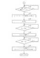
図5のステップS121において、メインコントローラ100は、操作手段35が操作されているか否かを判定する。メインコントローラ100は、操作手段35が操作されていないと判定した場合、ステップS122に移行する。メインコントローラ100は、操作手段35が操作されていると判定した場合、ステップS121の処理を再度行う。 In step S <b> 121 of FIG. 5, the
ステップS122において、メインコントローラ100は、非作業経過時間tiのカウントを開始する。非作業経過時間tiは、操作手段35を継続して操作していない時間、すなわち、作業用油圧アクチュエータ40を継続して駆動していない(作業を行っていない)時間である。メインコントローラ100は、上記処理を行った後、ステップS123に移行する。 In step S122, the
ステップS123において、メインコントローラ100は、操作手段35が操作されているか否かを判定する。メインコントローラ100は、操作手段35が操作されていないと判定した場合、ステップS124に移行する。メインコントローラ100は、操作手段35が操作されていると判定した場合、ステップS121の処理を再度行う。 In step S123, the
ステップS124において、メインコントローラ100は、非作業経過時間tiが、予め設定される非作業判定閾値t1以上であるか否かを判定する。 In step S124, the
ここで、非作業判定閾値t1は、任意に設定される値であり、後述するステップS125においてエンジン10を停止させるべきと認められる非作業経過時間tiと同一の値に設定される。すなわち、非作業判定閾値t1は、断続的に作業を行う場合の作業と作業の合間の時間よりは長く、かつ、できるだけ短い時間に設定されることが、エンジン10の燃料の無駄な消費を抑制する上で望ましい。 Here, the non-work determination threshold value t1 is an arbitrarily set value, and is set to the same value as the non-work elapsed time ti that the
ステップS124において、メインコントローラ100は、非作業経過時間tiが非作業判定閾値t1以上であると判定した場合、ステップS125に移行する。メインコントローラ100は、非作業経過時間tiが非作業判定閾値t1以上でない、すなわち非作業判定閾値t1未満であると判定した場合、ステップS123の処理を再度行う。 In step S124, when the
ステップS125において、メインコントローラ100は、ECU101にエンジン10を停止させる旨の制御信号を送信する。当該制御信号を受信したECU101は、エンジン10を停止させる。また、メインコントローラ100は、クラッチ15に当該クラッチ15を切断する旨の制御信号を送信する。当該制御信号を受信したクラッチ15は切断され、出力軸11と入力軸23との間の動力伝達が遮断される。さらに、メインコントローラ100は、インバータ70にコンバータ回路及びインバータ回路のいずれも選択しない旨の制御信号を送信し、モータジェネレータ50を中立状態に切り換える。メインコントローラ100は、上記処理を行った後、ステップS126(図6参照)に移行する。 In step S125, the
図6のステップS126において、メインコントローラ100は、操作手段35が操作されているか否かを判定する。メインコントローラ100は、操作手段35が操作されていると判定した場合、ステップS127に移行する。メインコントローラ100は、操作手段35が操作されていないと判定した場合、ステップS126の処理を再度行う。 In step S126 of FIG. 6, the
ステップS127において、メインコントローラ100は、インバータ70にインバータ回路を選択する旨の制御信号を送信し、モータジェネレータ50を駆動状態に切り換える。 In step S127, the
この場合、メインコントローラ100は、モータジェネレータ50により駆動される第一油圧ポンプ21及び第二油圧ポンプ22の回転数Npが、ステップS125においてエンジン10を停止する際の当該エンジン10の目標回転数と一致するように、モータジェネレータ50の回転数を制御する。ここで、本実施形態においては、クラッチ15が接続されている場合、エンジン10の回転数Neは第一油圧ポンプ21及び第二油圧ポンプ22の回転数Npと同一である。つまり、ステップS127においてモータジェネレータ50により駆動される第一油圧ポンプ21及び第二油圧ポンプ22の回転数Npは、ステップS125においてエンジン10を停止する際の回転数Npと同一回転数になるように制御されることになる。 In this case, the
なお、本実施形態において、第一油圧ポンプ21及び第二油圧ポンプ22の回転数Npは、ポンプ回転数検出手段115により検出するものとしたが、本発明はこれに限るものではない。すなわち、インバータ70の周波数に基づいてモータジェネレータ50の回転数を検出することにより、当該モータジェネレータ50に連結された第一油圧ポンプ21及び第二油圧ポンプ22の回転数Npを検出することも可能である。 In the present embodiment, the rotation speed Np of the first
メインコントローラ100は、上記処理(ステップS127)を行った後、ステップS128に移行する。 After performing the above process (step S127), the
ステップS128において、メインコントローラ100は、吐出圧P1、吐出圧P2、押しのけ容積q1、押しのけ容積q2、及び回転数Npに基づいて、第一油圧ポンプ21及び第二油圧ポンプ22による吸収馬力Lpを算出する。メインコントローラ100は、上記処理を行った後、ステップS129に移行する。 In step S128, the
ステップS129において、メインコントローラ100は、吸収馬力Lpが予め設定される始動用出力閾値Dp2以上であるか否かを判定する。 In step S129, the
ここで、始動用出力閾値Dp2は、任意に設定される値であり、後述するステップS130においてエンジン10を始動させるべきと認められる吸収馬力Lpと同一の値に設定される。すなわち、始動用出力閾値Dp2は、大きな出力(吸収馬力Lp)が不要であり、低速トルク及び円滑な回転が重視される吸収馬力Lpの最大値と同一の値に設定されることが、エンジン10の燃料の無駄な消費を抑制する上で望ましい。 Here, the starting output threshold value Dp2 is a value that is arbitrarily set, and is set to the same value as the absorption horsepower Lp that is recognized to start the
ステップS129において、メインコントローラ100は、吸収馬力Lpが始動用出力閾値Dp2以上であると判定した場合、ステップS130に移行する。メインコントローラ100は、吸収馬力Lpが始動用出力閾値Dp2以上でない、すなわち始動用出力閾値Dp2未満であると判定した場合、ステップS129の処理を再度行う。 If the
ステップS130において、メインコントローラ100は、ECU101にエンジン10を始動させる旨の制御信号を送信する。当該制御信号を受信したECU101は、エンジン10を始動させる。メインコントローラ100は、上記処理を行った後、ステップS131に移行する。 In step S <b> 130, the
ステップS131において、メインコントローラ100は、エンジン10の回転数Neが第一油圧ポンプ21及び第二油圧ポンプ22の回転数Np以上であるか否かを判定する。メインコントローラ100は、回転数Neが回転数Np以上であると判定した場合、ステップS132に移行する。メインコントローラ100は、回転数Neが回転数Np以上でない、すなわち回転数Np未満であると判定した場合、ステップS131の処理を再度行う。 In step S131, the
ステップS132において、メインコントローラ100は、クラッチ15に当該クラッチ15を接続する旨の制御信号を送信する。当該制御信号を受信したクラッチ15は接続され、出力軸11と入力軸23との間の動力伝達が可能となる。また、メインコントローラ100は、インバータ70にコンバータ回路及びインバータ回路のいずれも選択しない旨の制御信号を送信し、モータジェネレータ50を中立状態に切り換える。 In step S <b> 132, the
以下では、上記ステップS125、ステップS127、ステップS130、及びステップS132の詳細について説明する。 Below, the detail of said step S125, step S127, step S130, and step S132 is demonstrated.
図5のステップS124において、非作業経過時間tiが非作業判定閾値t1以上であると判定された場合、オペレータによる作業が中断されたと推定される。この場合、ステップS125においてエンジン10を停止することによって、無駄な燃料の消費を抑制することができる。また、モータジェネレータ50を中立状態に切り換えることによって、バッテリ60に蓄えられた電力の無駄な消費を抑制することができる。 In step S124 of FIG. 5, when it is determined that the non-work elapsed time ti is equal to or greater than the non-work determination threshold value t1, it is estimated that the work by the operator is interrupted. In this case, useless fuel consumption can be suppressed by stopping the
図6のステップS126において、操作手段35が操作されたと判定された場合、オペレータによる作業が再開されたと推定される。この場合、ステップS127においてモータジェネレータ50を駆動状態に切り換えることによって、一般に低速トルクの高いモータジェネレータ50(電動機)によって速やかに第一油圧ポンプ21及び第二油圧ポンプ22を駆動することができる。 If it is determined in step S126 in FIG. 6 that the operation means 35 has been operated, it is estimated that the operation by the operator has been resumed. In this case, by switching the
ステップS129において、吸収馬力Lpが始動用出力閾値Dp2以上であると判定された場合、吸収馬力Lpが大きく、エンジン10により第一油圧ポンプ21及び第二油圧ポンプ22を駆動すべきと推定される。この場合、ステップS130においてエンジン10を自動的に始動させることができる。 When it is determined in step S129 that the absorption horsepower Lp is equal to or greater than the starting output threshold value Dp2, it is estimated that the absorption horsepower Lp is large and the
ステップS131において、エンジン10の回転数Neが第一油圧ポンプ21及び第二油圧ポンプ22の回転数Np以上であると判定された場合、エンジン10の回転数Neが第一油圧ポンプ21及び第二油圧ポンプ22を駆動するのに十分な回転数に到達したと推定される。この場合、ステップS132においてクラッチ15を接続するとともにモータジェネレータ50を中立状態に切り換えることによって、エンジン10と第一油圧ポンプ21及び第二油圧ポンプ22とを滑らかに連結することができる。また、エンジン10の回転数Neが十分な回転数に増加するまでは、モータジェネレータ50により第一油圧ポンプ21及び第二油圧ポンプ22が駆動されているため、クラッチ15を接続する際の当該第一油圧ポンプ21及び第二油圧ポンプ22の回転数Npの低下を防止することができる。特に、エンジン10の回転数Neが第一油圧ポンプ21及び第二油圧ポンプ22の回転数Npと同一になった時にクラッチ15を接続することで、エンジン10と第一油圧ポンプ21及び第二油圧ポンプ22とをさらに滑らかに連結することができる。 In step S131, when it is determined that the rotational speed Ne of the
なお、本実施形態においては、エンジン10の回転数Neが第一油圧ポンプ21及び第二油圧ポンプ22の回転数Np以上になった場合(ステップS131)、ステップS132に移行するものとしたが、本発明はこれに限るものではない。本実施形態においては、クラッチ15が接続された場合、エンジン10の回転数Neと第一油圧ポンプ21及び第二油圧ポンプ22の回転数Npは同一であるが、例えば、エンジン10と第一油圧ポンプ21及び第二油圧ポンプ22との間に減速装置が設けられた場合、両回転数(回転数Ne及び回転数Np)は異なる値になる。この場合は、クラッチ15の直前の回転数(本実施形態においては、出力軸11の回転数)が、クラッチ15の直後の回転数(本実施形態においては、入力軸23の回転数)以上になった場合、ステップS132に移行するものとすることもできる。すなわち、エンジン10の回転数Neが、エンジン10と第一油圧ポンプ21及び第二油圧ポンプ22とを滑らかに連結することができるような所定の値以上になった場合に、ステップS132に移行するものであれば良い。 In the present embodiment, when the rotational speed Ne of the
アイドルストップ選択手段122が「ON」ポジションに切り換えられている場合は、メインコントローラ100は上述のアイドルストップ制御を行うが、アイドルストップ選択手段122が「OFF」ポジションに切り換えられている場合、メインコントローラ100はアイドルストップ制御を行わない。すなわち、この場合、操作手段35が操作されていない状態が続いても、エンジン10が停止されたり、モータジェネレータ50の作動状態が切り換えられたりすることがない。このように、オペレータはアイドルストップ選択手段122を「ON」ポジション又は「OFF」ポジションに切り換えることによって、上述のアイドルストップ制御を行うか行わないかを任意に選択することができる。 When the idle stop selection means 122 is switched to the “ON” position, the
アイドルストップ選択手段122が「モータ駆動」ポジションに切り換えられている場合、メインコントローラ100は、エンジン10を停止し、クラッチ15を切断し、モータジェネレータ50を駆動状態に切り換えることによって、第一油圧ポンプ21及び第二油圧ポンプ22をモータジェネレータ50のみで駆動させる。このように、オペレータはエンジン10を始動させる必要がないと判断した場合、アイドルストップ選択手段122を「モータ駆動」ポジションに切り換えることによって、エンジン10を始動させることなくモータジェネレータ50のみで第一油圧ポンプ21及び第二油圧ポンプ22を駆動させることができる。これによって、オペレータの任意でエンジン10による燃料の消費を抑制することができる。また、エンジン10を停止させたまま作業を行うことが可能であり、当該エンジン10の騒音を発生させることなく静かに作業を行うことができる。 When the idle stop selection means 122 is switched to the “motor drive” position, the
以上の如く、本実施形態に係る動力伝達装置1は、バッテリ60と、バッテリ60からの電力の供給により回転駆動される電動機(モータジェネレータ50)と、エンジン10と、エンジン10を始動するためのセルモータ80と、モータジェネレータ50又はエンジン10によって駆動される少なくとも1つの油圧ポンプ(第一油圧ポンプ21及び第二油圧ポンプ22)と、エンジン10から前記油圧ポンプへと伝達される動力を断接するクラッチ15と、バッテリ60からモータジェネレータ50への電力の供給を許可又は遮断する切換手段(インバータ70)と、作業用油圧アクチュエータ40を操作するための操作手段35と、操作手段35が操作されているか否かを検出する操作状態検出手段116と、エンジン10の回転数Neを検出するエンジン回転数検出手段と、前記油圧ポンプの回転数Npを検出するポンプ回転数検出手段115と、操作手段35が所定時間(非作業判定閾値t1)以上操作されていないことを検出した場合、エンジン10を停止し、クラッチ15を切断し、かつバッテリ60からモータジェネレータ50への電力の供給を遮断し、その後操作手段35が操作されたことを検出した場合、セルモータ80によりエンジン10を始動し、かつバッテリ60からモータジェネレータ50への電力の供給を許可し、エンジン10の回転数Neが所定の値(回転数Np)以上になった後にクラッチ15を接続し、かつバッテリ60からモータジェネレータ50への電力の供給を遮断するアイドルストップ制御を行う制御装置(メインコントローラ100及びECU101)と、を具備するものである。このように構成することにより、作業用油圧アクチュエータ40を操作しない場合にはエンジン10を停止することで、燃料の無駄な消費を抑制することができる。エンジン10の再始動時には、エンジン10の回転数Neが所定の値(回転数Np)以上になるまではモータジェネレータ50により油圧ポンプを駆動し、所定の値以上になった後にはエンジン10で油圧ポンプを駆動する。これによって、エンジン10の再始動直後で当該エンジン10の回転数Neが低い場合であっても、油圧ポンプの回転数Npの低下を防止することができ、ひいては油圧ポンプが吐出する作動油の流量の低下を防止することができる。したがって、エンジン10の再始動時における作業用油圧アクチュエータ40の操作フィーリングの悪化を防止することができる。さらに、エンジン10の再始動時にはクラッチ15を切断しているため、油圧ポンプの起動トルクがエンジン10に加わることがない。したがって、特に低温環境下で作動油の粘度が高く、油圧ポンプの起動トルクが常温時よりも大きくなった場合であっても、エンジン10の始動性の悪化を防止することができる。 As described above, the power transmission device 1 according to this embodiment includes the battery 60, the electric motor (motor generator 50) that is rotationally driven by the supply of electric power from the battery 60, the
また、動力伝達装置1は、前記油圧ポンプの吐出圧(吐出圧P1及び吐出圧P2)を検出する圧力検出手段(第一圧力検出手段111及び第二圧力検出手段112)と、前記油圧ポンプの押しのけ容積(押しのけ容積q1及び押しのけ容積q2)を検出する容積検出手段(第一容積検出手段113及び第二容積検出手段114)と、を具備し、前記制御装置は、前記圧力検出手段、前記容積検出手段、及び前記ポンプ回転数検出手段115による検出値に基づいて前記油圧ポンプの吸収馬力Lpを算出し、前記アイドルストップ制御において、操作手段35が操作されたことを検出した場合であっても、吸収馬力Lpが所定値(始動用出力閾値Dp2)未満であるときは、エンジン10を始動することなくバッテリ60からモータジェネレータ50への電力の供給を許可し、吸収馬力Lpが所定値以上になったときは、エンジン10を始動するものである。このように構成することにより、前記油圧ポンプの吸収馬力Lpが小さい場合(軽負荷作業時)には、エンジン10を再始動させることなく、モータジェネレータ50のみで前記油圧ポンプを駆動することができる。これによって、燃料の消費を抑制するとともに、低速トルクが大きく回転が円滑なモータジェネレータ50で前記油圧ポンプを駆動することができ、作業性を向上させることができる。また、エンジン10を停止させたまま作業を行うことが可能であり、当該エンジン10の騒音を発生させることなく静かに作業を行うことができる。 The power transmission device 1 includes pressure detection means (first pressure detection means 111 and second pressure detection means 112) for detecting discharge pressures (discharge pressure P1 and discharge pressure P2) of the hydraulic pump, and the hydraulic pump. Volume detecting means (first volume detecting means 113 and second volume detecting means 114) for detecting a displacement volume (a displacement volume q1 and a displacement volume q2), and the control device includes the pressure detection means and the volume. Even when the absorption horsepower Lp of the hydraulic pump is calculated based on the detection value by the detection means and the pump rotation speed detection means 115 and it is detected that the operation means 35 is operated in the idle stop control. When the absorption horsepower Lp is less than a predetermined value (starting output threshold value Dp2), the motor generator is started from the battery 60 without starting the
また、動力伝達装置1は、前記アイドルストップ制御を行うか否かを選択するためのアイドルストップ選択手段122を具備し、前記制御装置は、アイドルストップ選択手段122により前記アイドルストップ制御を行わない選択がされた場合、前記アイドルストップ制御を行わないものである。このように構成することにより、前記アイドルストップ制御を行うか否かを、オペレータの任意で選択することができる。 The power transmission device 1 further includes idle stop selection means 122 for selecting whether or not to perform the idle stop control, and the control apparatus selects that the idle stop control is not performed by the idle stop selection means 122. In the case where the operation is performed, the idle stop control is not performed. With this configuration, it is possible for the operator to arbitrarily select whether or not to perform the idle stop control.
なお、図6のステップS132において、メインコントローラ100は単にクラッチ15を接続するものとしたが、本発明はこれに限るものではない。すなわち、メインコントローラ100は、所定時間の間はクラッチ15を完全に接続しない、いわゆる半クラッチ状態に保持することによって、エンジン10の出力を徐徐に上昇させながらクラッチ15を接続するように構成することも可能である。これによって、エンジン10に急激に負荷が加わり、エンジン10の回転数Neが急激に減少することを防止することができる。 6, the
1 動力伝達装置
10 エンジン
15 クラッチ
21 第一油圧ポンプ(油圧ポンプ)
22 第二油圧ポンプ(油圧ポンプ)
35 操作手段
50 モータジェネレータ(電動機)
60 バッテリ
70 インバータ(切換手段)
80 セルモータ
100 メインコントローラ(制御装置)
101 エンジンコントローラユニット(制御装置)
110 吸収馬力検出手段
111 第一圧力検出手段(圧力検出手段)
112 第二圧力検出手段(圧力検出手段)
113 第一容積検出手段(容積検出手段)
114 第二容積検出手段(容積検出手段)
115 ポンプ回転数検出手段
116 操作状態検出手段
117 充電状態検出手段
122 アイドルストップ選択手段1
22 Second hydraulic pump (hydraulic pump)
35 Operating means 50 Motor generator (electric motor)
60 battery 70 inverter (switching means)
80
101 Engine controller unit (control device)
110 Absorption horsepower detection means 111 First pressure detection means (pressure detection means)
112 Second pressure detection means (pressure detection means)
113 First volume detection means (volume detection means)
114 Second volume detection means (volume detection means)
115 Pump speed detection means 116 Operation state detection means 117 Charge state detection means 122 Idle stop selection means
Claims (2)
Translated fromJapaneseエンジンと、前記エンジンを始動するためのセルモータと、
前記電動機又は前記エンジンによって駆動される少なくとも1つの油圧ポンプと、
前記エンジンから前記油圧ポンプへと伝達される動力を断接するクラッチと、
前記バッテリから前記電動機への電力の供給を許可又は遮断する切換手段と、
作業用油圧アクチュエータを操作するための操作手段と、
前記操作手段が操作されているか否かを検出する操作状態検出手段と、
前記エンジンの回転数を検出するエンジン回転数検出手段と、
前記油圧ポンプの回転数を検出するポンプ回転数検出手段と、
前記操作手段が所定時間以上操作されていないことを検出した場合、前記エンジンを停止し、前記クラッチを切断し、かつ前記バッテリから前記電動機への電力の供給を遮断し、その後前記操作手段が操作されたことを検出した場合、前記セルモータにより前記エンジンを始動し、かつ前記バッテリから前記電動機への電力の供給を許可し、前記エンジンの回転数が所定の値以上になった後に前記クラッチを接続し、かつ前記バッテリから前記電動機への電力の供給を遮断するアイドルストップ制御を行う制御装置とを具備し、
前記油圧ポンプの吐出圧を検出する圧力検出手段と、
前記油圧ポンプの押しのけ容積を検出する容積検出手段とを具備し、
前記制御装置は、前記圧力検出手段、前記容積検出手段、及び前記ポンプ回転数検出手段による検出値に基づいて前記油圧ポンプの吸収馬力を算出し、
前記アイドルストップ制御において、前記操作手段が操作されたことを検出した場合であっても、前記吸収馬力が所定値未満であるときは、前記エンジンを始動することなく前記バッテリから前記電動機への電力の供給を許可し、
前記吸収馬力が所定値以上になったときは、前記エンジンを始動する
ことを特徴とする動力伝達装置。A battery and an electric motor that is rotationally driven by the supply of electric power from the battery;
An engine and a cell motor for starting the engine;
At least one hydraulic pump driven by the electric motor or the engine;
A clutch for connecting / disconnecting power transmitted from the engine to the hydraulic pump;
Switching means for permitting or cutting off the supply of electric power from the battery to the electric motor;
Operating means for operating the working hydraulic actuator;
Operation state detection means for detecting whether or not the operation means is being operated;
Engine speed detecting means for detecting the engine speed;
Pump rotation number detecting means for detecting the rotation number of the hydraulic pump;
When it is detected that the operating means has not been operated for a predetermined time or more, the engine is stopped, the clutch is disconnected, and the supply of electric power from the battery to the electric motor is cut off, and then the operating means is operated. When it is detected that the engine has been started, the engine is started by the cell motor, and power supply from the battery to the electric motor is permitted, and the clutch is connected after the engine speed reaches a predetermined value or more. And a control device that performs idle stop control for cutting off the supply of power from the battery to the electric motor,
Pressure detecting means for detecting the discharge pressure of the hydraulic pump;
Comprising volume detecting means for detecting the displacement of the hydraulic pump;
The control device calculates an absorption horsepower of the hydraulic pump based on detection values by the pressure detection means, the volume detection means, and the pump rotation speed detection means,
In the idle stop control, even when it is detected that the operating means is operated, when the absorbed horsepower is less than a predetermined value, the power from the battery to the electric motor is not started without starting the engine. Allowed the supply of
The power transmission device, wherein the engine is started when the absorption horsepower becomes a predetermined value or more .
Priority Applications (5)
| Application Number | Priority Date | Filing Date | Title |
|---|---|---|---|
| JP2010241105AJP5764310B2 (en) | 2010-10-27 | 2010-10-27 | Power transmission device |
| EP11836158.3AEP2639362B1 (en) | 2010-10-27 | 2011-10-21 | Power transmission apparatus |
| PCT/JP2011/074295WO2012057024A1 (en) | 2010-10-27 | 2011-10-21 | Power transmission device |
| CN201180051421.1ACN103180521B (en) | 2010-10-27 | 2011-10-21 | Power transmission device |
| US13/882,015US9114808B2 (en) | 2010-10-27 | 2011-10-21 | Power transmission apparatus |
Applications Claiming Priority (1)
| Application Number | Priority Date | Filing Date | Title |
|---|---|---|---|
| JP2010241105AJP5764310B2 (en) | 2010-10-27 | 2010-10-27 | Power transmission device |
Publications (2)
| Publication Number | Publication Date |
|---|---|
| JP2012092576A JP2012092576A (en) | 2012-05-17 |
| JP5764310B2true JP5764310B2 (en) | 2015-08-19 |
Family
ID=45993734
Family Applications (1)
| Application Number | Title | Priority Date | Filing Date |
|---|---|---|---|
| JP2010241105AExpired - Fee RelatedJP5764310B2 (en) | 2010-10-27 | 2010-10-27 | Power transmission device |
Country Status (5)
| Country | Link |
|---|---|
| US (1) | US9114808B2 (en) |
| EP (1) | EP2639362B1 (en) |
| JP (1) | JP5764310B2 (en) |
| CN (1) | CN103180521B (en) |
| WO (1) | WO2012057024A1 (en) |
Families Citing this family (26)
| Publication number | Priority date | Publication date | Assignee | Title |
|---|---|---|---|---|
| DE102011107084A1 (en)* | 2011-07-11 | 2013-01-17 | Liebherr-Hydraulikbagger Gmbh | working machine |
| DE102012009000A1 (en)* | 2012-05-04 | 2013-11-07 | Bomag Gmbh | Operating element of a construction machine |
| CN102767205A (en)* | 2012-07-26 | 2012-11-07 | 梁富春 | Clutch type variable-speed pump of loader |
| US9303715B2 (en) | 2013-03-10 | 2016-04-05 | Oshkosh Defense, Llc | Limiting system for a vehicle suspension component |
| CN103671620A (en)* | 2013-12-03 | 2014-03-26 | 天津工程机械研究院 | Hydraulic pump clutch for engineering machines |
| JP6167387B2 (en)* | 2013-12-04 | 2017-07-26 | 日立建機株式会社 | Hybrid work vehicle |
| GB2531763A (en) | 2014-10-29 | 2016-05-04 | Bamford Excavators Ltd | Working machine |
| GB2531762A (en) | 2014-10-29 | 2016-05-04 | Bamford Excavators Ltd | Working machine |
| JP6007287B1 (en)* | 2015-05-14 | 2016-10-12 | 西芝電機株式会社 | Engine-driven pump with generator |
| JP6524019B2 (en) | 2016-05-18 | 2019-06-05 | 日立建機株式会社 | Construction machinery |
| US10611203B1 (en) | 2017-04-27 | 2020-04-07 | Oshkosh Defense, Llc | Suspension element lockout |
| US10900485B2 (en)* | 2017-11-13 | 2021-01-26 | Illinois Tool Works Inc. | Methods and systems for air compressor and engine driven control |
| JP7393872B2 (en)* | 2019-03-20 | 2023-12-07 | 株式会社Subaru | drive system |
| US11137052B2 (en) | 2019-08-29 | 2021-10-05 | Deere & Company | Transmission assembly with integrated CVP |
| US11351983B2 (en) | 2019-10-31 | 2022-06-07 | Deere & Company | Power control system with transmission transient boost function |
| US11846085B2 (en)* | 2020-02-17 | 2023-12-19 | Deere & Company | Energy management system for a hybrid vehicle with an electrically powered hydraulic system |
| CN111636510B (en)* | 2020-05-26 | 2024-08-23 | 湖南金蚂蚁智能装备股份有限公司 | Electrical system of miniature electric loader |
| US11325459B2 (en) | 2020-10-09 | 2022-05-10 | Deere & Company | Low profile transmission assembly with integrated CVP |
| KR102406200B1 (en)* | 2020-12-22 | 2022-06-08 | 울산대학교 산학협력단 | Continuously Variable Powertrain With Integrated Hydraulic Flywheel To Saver Energy In The Boom System |
| US11613246B2 (en) | 2021-01-21 | 2023-03-28 | Deere & Company | Power control system with engine throttle shift function |
| US11628822B2 (en) | 2021-02-09 | 2023-04-18 | Deere & Company | Power control system with stall prevention clutch modulation function |
| US11820361B2 (en) | 2021-11-30 | 2023-11-21 | Deere & Company | Transmission assembly with electrical machine unit for improved shift quality |
| US11585412B1 (en) | 2021-12-22 | 2023-02-21 | Deere & Company | Electronically-variable, dual-path power shift transmission for work vehicles |
| US11607948B1 (en) | 2021-12-22 | 2023-03-21 | Deere & Company | Electronically-variable power shift transmission for work vehicles |
| US11913528B1 (en) | 2022-10-28 | 2024-02-27 | Deere & Company | Multi-mode continuously variable transmission assembly with drop set arrangement |
| CN119253830B (en)* | 2024-09-25 | 2025-08-01 | 苏州吉龙机械有限公司 | Control method and control system for distributed backup power supply chassis of excavator |
Family Cites Families (15)
| Publication number | Priority date | Publication date | Assignee | Title |
|---|---|---|---|---|
| JP3587957B2 (en)* | 1997-06-12 | 2004-11-10 | 日立建機株式会社 | Engine control device for construction machinery |
| JP3381613B2 (en)* | 1998-03-20 | 2003-03-04 | 日産自動車株式会社 | Drive control device for hybrid vehicle |
| JP2001012275A (en)* | 1999-06-30 | 2001-01-16 | Kobelco Contstruction Machinery Ltd | Construction machine with feeding function |
| JP3931004B2 (en)* | 1999-09-27 | 2007-06-13 | 新キャタピラー三菱株式会社 | Hybrid hydraulic system and hydraulic construction machine |
| JP2002166736A (en)* | 2000-11-30 | 2002-06-11 | Isuzu Motors Ltd | Hybrid car |
| JP4179465B2 (en)* | 2002-07-31 | 2008-11-12 | 株式会社小松製作所 | Construction machinery |
| JP4386256B2 (en)* | 2003-10-28 | 2009-12-16 | 日立建機株式会社 | Hybrid construction vehicle |
| JP2005237178A (en)* | 2004-02-23 | 2005-09-02 | Kobelco Contstruction Machinery Ltd | Power source apparatus for working machine |
| JP4052483B2 (en)* | 2006-05-30 | 2008-02-27 | 三菱重工業株式会社 | Work vehicle |
| JP2008121659A (en)* | 2006-10-20 | 2008-05-29 | Kobelco Contstruction Machinery Ltd | Hybrid operation machine |
| KR100941239B1 (en)* | 2008-03-14 | 2010-02-10 | 현대자동차주식회사 | Torque control method of hybrid vehicle |
| CN101980881B (en)* | 2008-03-27 | 2013-12-18 | 力至优三菱叉车株式会社 | Hybrid industrial vehicle |
| US7980073B2 (en)* | 2008-05-08 | 2011-07-19 | Caterpillar Inc. | Hybrid system for a powertrain and hydraulic system |
| DE102008027658A1 (en)* | 2008-06-10 | 2009-12-17 | Bayerische Motoren Werke Aktiengesellschaft | Method for starting internal combustion engine of hybrid vehicle, involves starting internal combustion engine from drove operation mode, in which internal combustion engine is deactivated and is decoupled by coupling device |
| JP5764311B2 (en)* | 2010-10-27 | 2015-08-19 | ヤンマー株式会社 | Power transmission device |
- 2010
- 2010-10-27JPJP2010241105Apatent/JP5764310B2/ennot_activeExpired - Fee Related
- 2011
- 2011-10-21USUS13/882,015patent/US9114808B2/ennot_activeExpired - Fee Related
- 2011-10-21WOPCT/JP2011/074295patent/WO2012057024A1/enactiveApplication Filing
- 2011-10-21CNCN201180051421.1Apatent/CN103180521B/ennot_activeExpired - Fee Related
- 2011-10-21EPEP11836158.3Apatent/EP2639362B1/ennot_activeNot-in-force
Also Published As
| Publication number | Publication date |
|---|---|
| EP2639362A4 (en) | 2017-08-09 |
| US9114808B2 (en) | 2015-08-25 |
| EP2639362B1 (en) | 2019-03-06 |
| WO2012057024A1 (en) | 2012-05-03 |
| CN103180521A (en) | 2013-06-26 |
| US20130211655A1 (en) | 2013-08-15 |
| CN103180521B (en) | 2015-05-06 |
| JP2012092576A (en) | 2012-05-17 |
| EP2639362A1 (en) | 2013-09-18 |
Similar Documents
| Publication | Publication Date | Title |
|---|---|---|
| JP5764310B2 (en) | Power transmission device | |
| JP5764311B2 (en) | Power transmission device | |
| EP1834854B1 (en) | Hybrid construction machine | |
| JP5055948B2 (en) | Hybrid work machine | |
| JP5401992B2 (en) | Power source device for hybrid work machine | |
| EP3141442B1 (en) | Hybrid work machine | |
| JP6300943B2 (en) | Hybrid construction machine | |
| US9567916B2 (en) | Engine control apparatus and construction machine | |
| KR20110012037A (en) | Engine Speed Change Reduction Control System and Method for Hybrid Construction Equipment | |
| US20160340865A1 (en) | Shovel | |
| CN105939913B (en) | Excavator | |
| WO2016024642A1 (en) | Engine control device for hybrid construction machinery, hybrid construction machinery, and engine control method for hybrid construction machinery | |
| WO2012074098A1 (en) | Power transmitting device for hydraulic shovel | |
| KR101998379B1 (en) | Hybrid shovel and hybrid shovel control method |
Legal Events
| Date | Code | Title | Description |
|---|---|---|---|
| A621 | Written request for application examination | Free format text:JAPANESE INTERMEDIATE CODE: A621 Effective date:20130905 | |
| A131 | Notification of reasons for refusal | Free format text:JAPANESE INTERMEDIATE CODE: A131 Effective date:20141111 | |
| A521 | Request for written amendment filed | Free format text:JAPANESE INTERMEDIATE CODE: A523 Effective date:20141226 | |
| TRDD | Decision of grant or rejection written | ||
| A01 | Written decision to grant a patent or to grant a registration (utility model) | Free format text:JAPANESE INTERMEDIATE CODE: A01 Effective date:20150602 | |
| A61 | First payment of annual fees (during grant procedure) | Free format text:JAPANESE INTERMEDIATE CODE: A61 Effective date:20150615 | |
| R150 | Certificate of patent or registration of utility model | Ref document number:5764310 Country of ref document:JP Free format text:JAPANESE INTERMEDIATE CODE: R150 | |
| R250 | Receipt of annual fees | Free format text:JAPANESE INTERMEDIATE CODE: R250 | |
| S533 | Written request for registration of change of name | Free format text:JAPANESE INTERMEDIATE CODE: R313533 | |
| R350 | Written notification of registration of transfer | Free format text:JAPANESE INTERMEDIATE CODE: R350 | |
| LAPS | Cancellation because of no payment of annual fees |