JP5763619B2 - Medical device - Google Patents
Medical deviceDownload PDFInfo
- Publication number
- JP5763619B2 JP5763619B2JP2012504343AJP2012504343AJP5763619B2JP 5763619 B2JP5763619 B2JP 5763619B2JP 2012504343 AJP2012504343 AJP 2012504343AJP 2012504343 AJP2012504343 AJP 2012504343AJP 5763619 B2JP5763619 B2JP 5763619B2
- Authority
- JP
- Japan
- Prior art keywords
- main body
- unit
- slide
- input connector
- connector
- Prior art date
- Legal status (The legal status is an assumption and is not a legal conclusion. Google has not performed a legal analysis and makes no representation as to the accuracy of the status listed.)
- Active
Links
Images


Classifications
- A—HUMAN NECESSITIES
- A61—MEDICAL OR VETERINARY SCIENCE; HYGIENE
- A61B—DIAGNOSIS; SURGERY; IDENTIFICATION
- A61B18/00—Surgical instruments, devices or methods for transferring non-mechanical forms of energy to or from the body
- A61B18/04—Surgical instruments, devices or methods for transferring non-mechanical forms of energy to or from the body by heating
- A61B18/12—Surgical instruments, devices or methods for transferring non-mechanical forms of energy to or from the body by heating by passing a current through the tissue to be heated, e.g. high-frequency current
- A61B18/1206—Generators therefor
- A61B18/1233—Generators therefor with circuits for assuring patient safety
- A—HUMAN NECESSITIES
- A61—MEDICAL OR VETERINARY SCIENCE; HYGIENE
- A61B—DIAGNOSIS; SURGERY; IDENTIFICATION
- A61B18/00—Surgical instruments, devices or methods for transferring non-mechanical forms of energy to or from the body
- A61B18/04—Surgical instruments, devices or methods for transferring non-mechanical forms of energy to or from the body by heating
- A61B18/12—Surgical instruments, devices or methods for transferring non-mechanical forms of energy to or from the body by heating by passing a current through the tissue to be heated, e.g. high-frequency current
- A61B18/14—Probes or electrodes therefor
- A61B18/1477—Needle-like probes
- A—HUMAN NECESSITIES
- A61—MEDICAL OR VETERINARY SCIENCE; HYGIENE
- A61B—DIAGNOSIS; SURGERY; IDENTIFICATION
- A61B18/00—Surgical instruments, devices or methods for transferring non-mechanical forms of energy to or from the body
- A61B18/04—Surgical instruments, devices or methods for transferring non-mechanical forms of energy to or from the body by heating
- A61B18/12—Surgical instruments, devices or methods for transferring non-mechanical forms of energy to or from the body by heating by passing a current through the tissue to be heated, e.g. high-frequency current
- A61B18/14—Probes or electrodes therefor
- A61B18/1492—Probes or electrodes therefor having a flexible, catheter-like structure, e.g. for heart ablation
- A—HUMAN NECESSITIES
- A61—MEDICAL OR VETERINARY SCIENCE; HYGIENE
- A61B—DIAGNOSIS; SURGERY; IDENTIFICATION
- A61B18/00—Surgical instruments, devices or methods for transferring non-mechanical forms of energy to or from the body
- A61B18/18—Surgical instruments, devices or methods for transferring non-mechanical forms of energy to or from the body by applying electromagnetic radiation, e.g. microwaves
- A61B18/1815—Surgical instruments, devices or methods for transferring non-mechanical forms of energy to or from the body by applying electromagnetic radiation, e.g. microwaves using microwaves
- A—HUMAN NECESSITIES
- A61—MEDICAL OR VETERINARY SCIENCE; HYGIENE
- A61B—DIAGNOSIS; SURGERY; IDENTIFICATION
- A61B18/00—Surgical instruments, devices or methods for transferring non-mechanical forms of energy to or from the body
- A61B18/18—Surgical instruments, devices or methods for transferring non-mechanical forms of energy to or from the body by applying electromagnetic radiation, e.g. microwaves
- A61B18/20—Surgical instruments, devices or methods for transferring non-mechanical forms of energy to or from the body by applying electromagnetic radiation, e.g. microwaves using laser
- A—HUMAN NECESSITIES
- A61—MEDICAL OR VETERINARY SCIENCE; HYGIENE
- A61B—DIAGNOSIS; SURGERY; IDENTIFICATION
- A61B18/00—Surgical instruments, devices or methods for transferring non-mechanical forms of energy to or from the body
- A61B2018/00315—Surgical instruments, devices or methods for transferring non-mechanical forms of energy to or from the body for treatment of particular body parts
- A61B2018/00345—Vascular system
- A61B2018/00351—Heart
- A—HUMAN NECESSITIES
- A61—MEDICAL OR VETERINARY SCIENCE; HYGIENE
- A61B—DIAGNOSIS; SURGERY; IDENTIFICATION
- A61B18/00—Surgical instruments, devices or methods for transferring non-mechanical forms of energy to or from the body
- A61B2018/00571—Surgical instruments, devices or methods for transferring non-mechanical forms of energy to or from the body for achieving a particular surgical effect
- A61B2018/0063—Sealing
- A—HUMAN NECESSITIES
- A61—MEDICAL OR VETERINARY SCIENCE; HYGIENE
- A61B—DIAGNOSIS; SURGERY; IDENTIFICATION
- A61B18/00—Surgical instruments, devices or methods for transferring non-mechanical forms of energy to or from the body
- A61B2018/0091—Handpieces of the surgical instrument or device
- A61B2018/00916—Handpieces of the surgical instrument or device with means for switching or controlling the main function of the instrument or device
- A—HUMAN NECESSITIES
- A61—MEDICAL OR VETERINARY SCIENCE; HYGIENE
- A61B—DIAGNOSIS; SURGERY; IDENTIFICATION
- A61B18/00—Surgical instruments, devices or methods for transferring non-mechanical forms of energy to or from the body
- A61B18/04—Surgical instruments, devices or methods for transferring non-mechanical forms of energy to or from the body by heating
- A61B18/12—Surgical instruments, devices or methods for transferring non-mechanical forms of energy to or from the body by heating by passing a current through the tissue to be heated, e.g. high-frequency current
- A61B18/14—Probes or electrodes therefor
- A61B2018/1405—Electrodes having a specific shape
- A61B2018/1425—Needle
- A61B2018/143—Needle multiple needles
- A—HUMAN NECESSITIES
- A61—MEDICAL OR VETERINARY SCIENCE; HYGIENE
- A61B—DIAGNOSIS; SURGERY; IDENTIFICATION
- A61B18/00—Surgical instruments, devices or methods for transferring non-mechanical forms of energy to or from the body
- A61B18/18—Surgical instruments, devices or methods for transferring non-mechanical forms of energy to or from the body by applying electromagnetic radiation, e.g. microwaves
- A61B18/1815—Surgical instruments, devices or methods for transferring non-mechanical forms of energy to or from the body by applying electromagnetic radiation, e.g. microwaves using microwaves
- A61B2018/1861—Surgical instruments, devices or methods for transferring non-mechanical forms of energy to or from the body by applying electromagnetic radiation, e.g. microwaves using microwaves with an instrument inserted into a body lumen or cavity, e.g. a catheter
Landscapes
- Health & Medical Sciences (AREA)
- Surgery (AREA)
- Engineering & Computer Science (AREA)
- Life Sciences & Earth Sciences (AREA)
- Biomedical Technology (AREA)
- Otolaryngology (AREA)
- Nuclear Medicine, Radiotherapy & Molecular Imaging (AREA)
- Plasma & Fusion (AREA)
- Physics & Mathematics (AREA)
- Heart & Thoracic Surgery (AREA)
- Medical Informatics (AREA)
- Molecular Biology (AREA)
- Animal Behavior & Ethology (AREA)
- General Health & Medical Sciences (AREA)
- Public Health (AREA)
- Veterinary Medicine (AREA)
- Surgical Instruments (AREA)
Description
Translated fromJapanese本発明は、生体を加熱治療する医療用デバイスに関し、特に、医療用デバイスを操作する手元操作部の改良に関する。 The present invention relates to a medical device that heats and treats a living body, and more particularly, to an improvement in a hand operation unit that operates a medical device.
最近、脳卒中や偏頭痛の心原性要因として卵円孔開存症(以下、PFO:Patent Foramen Ovale)に対する治療デバイスとして、下記特許文献1に記載のものが提案されている。 Recently, as a therapeutic device for patent foramen ovale (hereinafter referred to as PFO) as a cardiogenic factor of stroke or migraine, a device described in
このPFO閉鎖デバイスは、器具を右心房から左心房に向けて卵円孔を挿通し、卵円孔を閉鎖するように卵円孔弁を引き寄せて、卵円孔弁と心房中隔を一対の電極により挟持し、両電極から電気エネルギを印加することにより生体組織を接合するものである。 This PFO closure device inserts the foramen into the foramen from the right atrium to the left atrium, pulls the foramen valve to close the foramen, and connects the foramen valve to the atrial septum. The living tissue is joined by being sandwiched between electrodes and applying electric energy from both electrodes.
このデバイスでは、一方が針電極からなる穿刺部材、他方が穿刺部材との間で卵円孔弁と心房中隔を挟持する挟持部材とした挟圧手段を使用し、穿刺部材を卵円孔弁に穿刺した後、他方の電極である挟持部材との間で卵円孔弁と心房中隔を挟持し、生体組織に電気エネルギを印加して接合を行っている。 In this device, one of the puncture members consisting of a needle electrode and the other is a pinching member that sandwiches the foramen valve and the atrial septum between the puncture member, and the puncture member is the oval hole valve. After the puncture, the foramen ovale and the atrial septum are held between the other electrode, ie, the holding member, and the living tissue is joined by applying electric energy.
このデバイスは、先天性の心房中隔欠損症(ASD)、PFO、心室中隔欠損症(VSD)、動脈管開存症(PDA)といった欠損を閉鎖する場合にも使用でき、汎用性の高いものであり、特に、体内に異物を留置せず、構成が簡単で、手技も容易となり、確実に卵円孔弁と心房中隔を接合できる。 This device can also be used to close defects such as congenital atrial septal defect (ASD), PFO, ventricular septal defect (VSD), patent ductus arteriosus (PDA), and is highly versatile In particular, no foreign substance is placed in the body, the structure is simple, the procedure is easy, and the foramen valve and the atrial septum can be reliably joined.
ところで、血液中に曝された挟圧手段(電極)に電気エネルギを印加すると、挟圧手段に血栓が付着しやすくなることもあり、生体組織を接合するための電極に、不用意に電気エネルギが印加されることは望ましくない。 By the way, if electrical energy is applied to the clamping means (electrode) exposed to blood, thrombi may easily adhere to the clamping means, and electrical energy is inadvertently applied to the electrode for joining living tissues. It is not desirable to be applied.
本発明は、上述した課題を解決するためになされたもので、不用意に電気エネルギが印加されることを抑制できる安全性の高い医療用デバイスを提供することを目的とする。 The present invention has been made to solve the above-described problems, and an object of the present invention is to provide a highly safe medical device that can suppress inadvertent application of electrical energy.
上記目的を達成する本発明の医療用デバイスは、カテーテルの先端側に設けられて生体組織を加熱する加熱部と、前記カテーテルの基端部に設けられて前記加熱部のカテーテルに対する進退動を操作する手元操作部と、を備えた医療用デバイスであって、前記手元操作部は、前記カテーテルに連結される本体部と、前記加熱部と連結されて前記本体部と近接離間可能なスライド部と、前記スライド部に連結されたガイド部と、前記本体部の基端部に設けられて、前記加熱部と電気的に接続され、かつ電気エネルギを供給するための出力コネクタが接続可能な入力コネクタが設けられた接続孔と、を備え、前記入力コネクタが設けられる前記本体部と異なる部材である前記ガイド部は、ガイドバーを備え、前記ガイドバーには、切欠部が設けられ、前記スライド部を前記本体部に対して後退させて前記接続孔と前記切欠部とが一致することで前記入力コネクタと出力コネクタが電気的に接続可能となり、前記加熱部から熱エネルギを付与可能となることを特徴とする医療用デバイスである。The medical device of the present invention that achieves the above-mentioned object is provided with a heating unit that is provided on the distal end side of the catheter and heats the living tissue, and is operated at the proximal end portion of the catheter to control the advance and retreat of the heating unit with respect to the catheter. a hand operation unit which provides a medical device with said operation portionincludes a main body portion connected to thefront Symbol catheter, wherein coupled with the heating portion the main body portion and the near-separable slide portion When thefront Symbol slideportion coupleda guide portion, provided at thebase end portion of said body portion, said heating unit and is electrically connected, and an output connector for supplying electrical energy connectablewith the input connectoris connected to the hole provided Do, the said guide portion and the input connector are different members and the body portion is provided, a guide bar, the guide bar, notch is provided et al The slide part is moved backward with respect to the main body part so that the connection hole and the cutout part coincide with each other so that the input connector and the output connector can be electrically connected, and heat energy can be applied from the heating part. It is a medical device characterized bybecoming .
本発明に係る医療用デバイスは、本体部、スライド部およびガイド部のうち前記入力コネクタが設けられる部材と異なる部材の1つが、入力コネクタと出力コネクタの接続を阻害する位置に配置され、かつガイド部が本体部またはスライド部に対して移動して加熱部が生体組織を加熱可能な位置に移動した際に、入力コネクタと出力コネクタの接続が可能となるように接続調整部が設けられるため、加熱部が生体組織を加熱可能な位置に移動するまで不用意な電気エネルギの印加を確実に防止でき、安全性を向上できる。 In the medical device according to the present invention, one of the main body portion, the slide portion, and the guide portion, which is different from the member provided with the input connector, is disposed at a position where the connection between the input connector and the output connector is obstructed. When the part moves relative to the main body part or the slide part and the heating part moves to a position where the living tissue can be heated, a connection adjustment part is provided so that the input connector and the output connector can be connected. Until the heating unit moves to a position where the living tissue can be heated, inadvertent application of electrical energy can be reliably prevented, and safety can be improved.
前記接続調整部が、前記スライド部が前記本体部に対して一定範囲内の相対的位置にある際に、前記入力コネクタと出力コネクタの接続を許容する大きさを有するようにすれば、個体差のある生体組織に柔軟に対応しつつ、不用意な電気エネルギの印加を抑制して安全性を向上できる。 If the connection adjustment unit has a size that allows connection between the input connector and the output connector when the slide unit is in a relative position within a certain range with respect to the main body unit, individual differences may occur. It is possible to improve safety by suppressing inadvertent application of electrical energy while flexibly dealing with a living tissue.
前記本体部、スライド部またはガイド部に、前記スライド部の移動によって前記加熱部と入力コネクタとの間を電気的に接続または解除するスイッチが設けられ、前記スイッチによって電気的接続がなされる前記スライド部の位置に対応して、前記入力コネクタと出力コネクタの接続が可能となるように前記接続調整部が設けられるようにすれば、スイッチによっても不用意な電気エネルギの印加を抑制でき、より安全性を向上できる。 The slide that is electrically connected by the switch is provided in the main body portion, the slide portion, or the guide portion, and a switch that electrically connects or disconnects the heating portion and the input connector by moving the slide portion is provided. If the connection adjustment part is provided so that the input connector and the output connector can be connected in accordance with the position of the part, it is possible to suppress the inadvertent application of electrical energy even by the switch, and it is safer. Can be improved.
前記接続調整部および出力コネクタに、前記出力コネクタが前記入力コネクタに接続された際に、互いに接触して前記スライド部の前記本体部に対する移動を固定する固定手段が設けられるようにすれば、出力コネクタが入力コネクタに接続された後の加熱部の移動を抑えることができ、より望ましい加熱を実現できる。 If the connection adjusting portion and the output connector are provided with a fixing means for fixing the movement of the slide portion relative to the main body portion when the output connector is connected to the input connector, an output is provided. The movement of the heating unit after the connector is connected to the input connector can be suppressed, and more desirable heating can be realized.
前記ガイド部が、前記入力コネクタと出力コネクタの接続が可能な状態において、前記本体部またはスライド部の所定の位置と一致するように表記された表示部を有するようにすれば、加熱部への電気エネルギの印加が可能であることを術者が容易に理解でき、さらに安全性を向上できる。 If the guide part has a display part written so as to coincide with a predetermined position of the main body part or the slide part in a state where the input connector and the output connector can be connected to the heating part, An operator can easily understand that electric energy can be applied, and safety can be further improved.
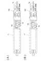
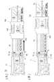
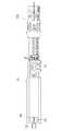
本実施形態の医療用デバイスは、PFO閉鎖デバイスであり、図1〜3を参照してまず概説する。なお、図2では、紙面の都合上、手元操作部70のみを縮小した状態で記載している。 The medical device of this embodiment is a PFO closure device and will first be outlined with reference to FIGS. In FIG. 2, only the
PFO閉鎖デバイスは、基端側に設けられた手元操作部70と、手元操作部70に基端が連結可能なガイディングカテーテル31と、手元操作部70に基端が取り付けられてガイディングカテーテル31内に設けられたカテーテル30と、カテーテル30の先端部分に設けられ、卵円孔弁M2及び心房中隔M1を挟持する挟圧手段Kと、挟圧手段Kにより挟持した部分の生体組織M(M1,M2の総称)を融着あるいは壊死させる電気エネルギを供給するエネルギ供給手段20と、挟圧手段Kによる手技を安定かつ正確に行なうための位置決め保持手段60(図2参照)と、を有している。なお、以下の説明において、デバイスの手元操作部70側を「基端側」、挟圧手段K側を「先端側」と称す。 The PFO closure device includes a
デバイスの使用に当っては、まず、ガイディングカテーテル31を、例えば、大腿静脈Jから挿入するが、このガイディングカテーテル31は、内部にカテーテル30の先端に設けられた挟圧手段Kをカテーテル30と共に収納した状態で挿入する。先端が手技を行なう心臓の部位まで到達した後、手元操作部70を操作して挟圧手段Kをカテーテル30から突出させ、卵円孔の欠損O(以下、単に卵円孔Oと称することもある)が生じている心臓の心房中隔M1と卵円孔弁M2の組織を挟持する。この挟持状態で挟圧手段Kに電気エネルギを供給し、両組織を加熱融着し、欠損Oを閉鎖する。すなわち、挟圧手段Kは、加熱部として機能する。なお、図中、「L」は左心房、「R」は右心房を示す。 In using the device, first, the guiding
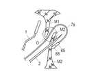
挟圧手段Kは、心房中隔M1の一側面に直接接触する挟持部材1と、卵円孔弁M2に穿刺する穿刺部材2とから構成されている。挟持部材1は、図2に示すように、全体的に扁平な板状の平板部1aと、基端部に接続された一対の線材部1bとから構成され、カテーテル30の先端に固定された先端チップ32のルーメンL3,L4(図3参照)により、その平面位置が規制されている。また、挟持部材1は、U字状に形成された線材部1bの基端側に1本の操作コード7bが接続され、操作コード7bを軸方向に進退させることにより、先端チップ32から突出して穿刺部材2との間に所定の挟持幅を形成したり、先端チップ32内に入り込むとき穿刺部材2側に向って接近し生体組織Mを挟持するように変位する。 The clamping means K includes a
一方、穿刺部材2は、先端チップ32に形成されたルーメンL1,L2(図3参照)によりその平面位置が規制された状態で進退可能に保持されており、また、U字状に形成された基端側に接続されている操作コード7cを操作することにより先端部が先端チップ32より出没し得るようになっている。 On the other hand, the
穿刺部材2は、軸直角断面が円形の、先端が鋭利に尖った極めて細い2本の針部材が相互に離間し、かつ、突出されると先端が拡開するように弾性が付与されている。また、針部材の数は、1本であっても3本以上であってもよい。 The
挟持部材1や穿刺部材2は、いずれも電極部材(加熱部)として機能するものであるが、挟持部材1や穿刺部材2をカテーテル30から出没させる操作コード7b、7c(図2参照)は、カテーテル30内を挿通し、後述の手元操作部70に設けられる入力コネクタ75、これに嵌合されるプラグである出力コネクタ87(図1参照)、出力コネクタ87の電極端子と接続された導線d(d1、d2の総称)及び制御部22を介してエネルギ供給手段20と電気的に接続される。また、導線d1又はd2のいずれか一方(本実施形態では導線d1)には、エネルギ供給手段20からの電流をオンオフ制御するために、足元に設置するフットスイッチSWが設けられている。なお、フットスイッチSWではなく、手元操作しやすいスイッチであってもよい。 The sandwiching
手元操作部70は、生体組織に存在する欠損の周辺にある生体組織Mを挟持する一対の電極部材からなる挟圧手段Kを、カテーテル30の先端から出没自在に操作する部分であるが、ここには、手をあまり動かすことなく小さな領域内ですべての操作を行うことができるように、下記する手段などが一括して設けられている。 The
つまり、手元操作部70には、図2に示すように、一方の電極部材である穿刺部材2を操作する針操作レバー78と、他方の電極部材である挟持部材1を操作するスライド部100と、挟圧手段Kの操作を補助するもので、手元操作部70及びカテーテル30内で軸方向移動可能に挿通された主操作ロッド7aと、スライド部100のスライド移動をロック−アンロックするロック−アンロック機構102(図9参照)を操作すると共に、主操作ロッド7aの軸方向移動をロックする押し片109と、熱エネルギを付与するエネルギ供給手段20と接続する電極端子を備えた入力コネクタ75と、が設けられている。 That is, as shown in FIG. 2, the
手元操作部70には、図4に示すように、各種手順の工程を目視可能とするため、術者が正しい操作を行うように導くための種々の表示が表面部分に付された、工程表示部H(H1〜H5の総称)が設けられている(工程表示部H5は図11(B)を参照)。 As shown in FIG. 4, the
工程表示部Hは、押し片109を操作し、主操作ロッド7aを牽引するロッド牽引工程の表示部H1と、穿刺部材2が生体組織を穿刺する穿刺工程の表示部H2と、スライド部100をスライド移動させ生体組織の挟持あるいは解放を行うスライド部移動工程の表示部H3と、入力コネクタ75をエネルギ供給手段20と接続する接続工程の表示部H4と、穿刺部材2を生体組織から後退させる穿刺部後退工程の表示部H5(図11(B)参照)とから構成され、それぞれ絵表示、番号および移動方向の矢印を用いて各工程をイメージさせる表示をしている。工程表示部Hでは、操作部材の操作が分かり易くなるように、各操作部材が着色された色と、各操作部材の移動方向を示す矢印の色とを同一色としている。 The process display unit H operates the
このように、各種工程の順番および移動方向が目視可能となるように、手元操作部70に工程表示部Hを設けると、術者は工程の順序を予め完全に習熟する必要はなく、工程表示部Hを見れば容易に理解でき、使用時の精神的負担を軽減し、手技を円滑かつ確実に行うことができ、さらに安全性も向上する。なお、工程表示部Hは、絵表示を用いて表示するのみでなく、箇条書き的に手元操作部70の表面に表示してもよい。 As described above, when the process display unit H is provided in the
なお、接続工程を行なう直前の操作は、挟圧手段Kにより生体組織を挟持する場合のみでなく、他の手技であってもよいことはいうまでもない。他の医療デバイスでは、エネルギ供給手段20と入力コネクタ75との接続を行なう直前の操作は種々あり、このような場合にも本実施形態は適用可能である。 Needless to say, the operation immediately before the connection step is not limited to the case where the living tissue is clamped by the clamping means K, but may be another procedure. In other medical devices, there are various operations immediately before the connection between the energy supply means 20 and the
針操作レバー78に関して、穿刺部材2を穿刺する方向に移動(図11(A)に示す状態から図11(B)に示す状態)させると、針操作レバー78の下面から、次に移動する方向の表示と、操作工程の順番を示す番号が現れるようになっている。このように、フールプルーフ機能、つまり術者が誤った操作をしても危険な状況を招かないように設計された安全機能が発揮され、手技の確実性、安全性が高まる。 When the
さらに手元操作部70を詳述すると、手元操作部70は、図2に示すように、ガイディングカテーテル31が連結される側の本体部71と、本体部71の基端側に本体部71に対して近接離間するようにガイドバー(ガイド部)40A、40B、40Cを介して連結されたスライド部100と、を有し、本体部71の上面には穿刺部材2を操作する針操作レバー78が設けられている。 Further, the
本体部71の表面側(上面側)には、図4に示すように、凹部77が形成され、ここに針操作レバー78が長手方向(白抜き矢印参照)に摺動可能に設けられている。針操作レバー78は、図5に示すように、本体部71に形成されたスリット(不図示)を挿通して内部空間76に達するように突出されたブラケット80を有し、このブラケット80に、穿刺部材2用の操作コード7cの基端側に設けられたL字状の端子81が連結されている。したがって、針操作レバー78(図4参照)をスリットに沿って摺動させると、端子81は、図5に示すように本体部71の内部に形成されたガイド溝82に沿って摺動し、操作コード7cを介して穿刺部材2を進退させるようになっている。 As shown in FIG. 4, a
本体部71の内部空間76の略中央には、後に詳述する主管63が挿通されている。主管63の基端側は、スライド部100に接着剤などにより連結され(図9参照)、スライド部100のスライド動作に応じて本体部71にガイドされて摺動する。 A
内部空間76内の主管63には、右端近傍に端子83が取り付けられ、主管63の摺動に伴って端子83も摺動するようになっている。端子83には、操作コード7bが接続されており、操作コード7bは、主管63の側部を通り挿通されている。これら端子81,83の移動終端位置には、スイッチとして機能する接触部材84,85が設けられている。勿論、穿刺部材2の電気系統と挟持部材1の電気系統とは、導通しないように絶縁されている。 A terminal 83 is attached to the
接触部材84,85は、導線d3,d4によって入力コネクタ75の両極に接続されており、穿刺部材2用の操作コード7cと挟持部材1用の操作コード7bの移動に伴って移動する端子81,83の移動完了位置に到達する前に、それぞれ端子81,83と接触するように構成している。 The
接触部材84,85をさらに詳述する。図6に示すように、接触部材84,85は、端子81,83と接触する当接部S1と、当接部S1から突出する脚部S2と、脚部S2の突出端が内部に収容される筒状カラーS3と、脚部S2を外方に向って弾発するバネS4とを有している。したがって、各当接部S1は、常時はバネS4により突出されるが、端子81,83により押されて後退するので、図示のように所定長の導通可能範囲Xを有するものとなる。 The
このようにすれば、人により卵円孔弁M2などの厚さや形状が相違することにより穿刺部材2の穿刺状態あるいは挟持部材1の挟持状態が相違し、端子81,83の移動完了位置が区々となっても、接触部材84,85は、端子81,83と確実に接触し、電気的導通が可能となり、手技の確実性が確保される。また、摺動的に電気的接触状態を形成する構成のものもあるが、このようなものに比べると、接触部材84,85と端子81,83との接触が確実になり、しかも故障も少なく、端子81,83のスライド操作も摩擦抵抗力が少なく軽いものとなる。 In this way, the puncture state of the
ただし、接触部材84,85と端子81,83の組がすべて弾性的接触状態である必要はなく、少なくとも一方のみであっても良く、他方は常時接触状態の構成としてもよい。または、接触部材84,85および端子81,83が設けられずに、両方とも常時接触状態の構成としてもよい。 However, the set of the
ガイドバー40A、40Bは、本体部71の内部の溝96A、96B内に設けられ、ガイドバー40Cは、不図示の溝内に設けられる。ガイドバー40A、40Bの一端には、図6に示すように、抜け止め用の突起部42A、42Bが設けられ、溝96A、96Bに設けられるストッパ部98A、98Bに当接して停止するようになっている。 The guide bars 40A and 40B are provided in the
主操作ロッド7aは、主管63内に設けられ、軸方向に牽引操作し挟圧手段Kの操作を補助する機能を有するもので、主管63内で軸線を中心として360度回転可能となっている。主操作ロッド7aが360度回転可能であれば、主操作ロッド7aの先端を卵円孔Oの近傍まで挿入し、これを回転的に位置変位させることにより卵円孔Oに挿通させることができる。この結果、卵円孔Oの状態が種々変形していても、その形状状態如何に拘わらず、デバイスの先端を卵円孔Oに挿通させることができ、手技を容易化、迅速化を図ることができる。 The
本体部71の先端部には、連結機構90(図2参照)の押ボタン93が設けられている。連結機構90は、本体部71に対するYコネクタ72の脱着を容易にするためのもので、押ボタン93を押した状態で、Yコネクタ72の基端部に設けられたフランジ部を本体部71に形成された挿通孔に嵌合させた後、押ボタン93の押圧を開放すると、図8に示すように、Yコネクタ72のフランジ部が摺動部材91の係合孔94に係合する。そして、摺動部材91がバネ部材92により弾発されて、フランジ部の抜け止め機能が発揮され、さらに押ボタン93を押すことで、Yコネクタ72が脱着可能となる構成となっている。 A
なお、手元操作部70の先端には、図2に示すように、造影剤などを注入することができるYコネクタ72を連結機構90により連結することが好ましいが、Yコネクタ72を使用しない場合には、本体部71にフランジ部を有するガイディングカテーテル31を直接連結することになる。なお、Yコネクタ72は、ガイディングカテーテル31の任意の位置に設けてもよい。 As shown in FIG. 2, it is preferable to connect a
本体部71の基端部には、出力コネクタ87の外形形状に対応した接続孔74が設けられており、この接続孔74の内部に、入力コネクタ75の電極端子が配置されている。 A
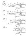
ガイドバー40Aは、側辺の一部が接続孔74に入り込むように配置されており、接続孔74に入り込んだガイドバー40Aは、出力コネクタ87の接続孔74への挿通を阻害して、出力コネクタ87の入力コネクタ75との接続を防止する。ガイドバー40Aの側辺の一部には、切欠部41(接続調整部)が形成されており、図7に示すように、この切欠部41が接続孔74と一致することで、出力コネクタ87が入力コネクタ75と接続可能となる。 The
ガイドバー40Aおよび主管63は、いずれもスライド部100に固定されているため、図12に示すようにスライド部100を基端方向へ後退させると、図6にて一点鎖線で示すように、ガイドバー40Aと共に主管63が本体部71の内部をスライドし、主管63に固定されている端子83が接触部材85に接触して挟持部材1と入力コネクタ75とが電気的に接続する。この接触部材85は、前述のように所定長の導通可能範囲Xを有しているため、この導通可能範囲X内において出力コネクタ87が入力コネクタ75に接続可能となるような大きさで、切欠部41がガイドバー40Aに形成される。 Since both the
すなわち、図7において一点鎖線で示す端子83、接触部材85および切欠部41は、スライド部100を後退させて端子83と接触部材85が最初に接触した状態(図7の実線で示す端子83、接触部材85および切欠部41を参照)から、更に導通可能範囲Xだけスライド部100を後退させた状態を示しているが、この範囲内において、切欠部41が接続孔74に一致してガイドバー40Aが接続孔74内に突出せず、出力コネクタ87(図1参照)がガイドバー40Aに阻害されずに入力コネクタ75に接続可能となっている。 That is, the terminal 83, the
このような構成を備えることで、手技中でも最も肝心な手技であって慎重さが要求されるエネルギ供給手段20と入力コネクタ75との接続を、生体組織Mの挟持が完了した後でなければ行えない構成になり、術者の肉体的あるいは精神的な状態如何に拘わらず、自ずと手技の安全性が高められる。 By providing such a configuration, the connection between the energy supply means 20 and the
また、図4に示すように、本体部71には、入力コネクタ75に隣接して開設された窓73が設けられている。そして、ガイドバー40Aには、切欠部41の近傍に「OK」表示部H6(図6参照)が表記されており、さらに、「OK」表示部H6から一定のピッチで数字(1〜5)が三角矢印と共に順に表記されている。 As shown in FIG. 4, the
スライド部100を本体部71から後退させることで、位置決め保持手段60をカテーテル30内に引き込み回収すると、手元操作部70では、ガイドバー40Aに表記された数字が、カウントダウンするように順番に窓73に現れ、最終的に「OK」表示部H6が窓73に現れる構成となっている。端子83は、導通可能範囲X内で接触部材85と接するため、この導通可能範囲Xにおいて「OK」表示部H6の全体が窓73に現れ、導通可能範囲Xから外れる場合には、「OK」表示部H6が窓73に現れない構成となっている。 When the positioning and holding means 60 is pulled into the
図9,10に示すロック−アンロック機構102は、スライド部100に設けられ、押し片109を押圧することによってスライド部100のスライド移動をロック−アンロックすると共に、主操作ロッド7aの軸方向移動をロック−アンロックする。 A lock-
ロック−アンロック機構102は、作動部材104を摺動させることによりスライド部100と本体部71とを連結したり、ロックを外すことによりスライド移動を可能にするスライド部用の第1ロック部R1と、主操作ロッド7aの先端部に設けられた、後述の位置決め保持手段60が生体組織Mの保持あるいは位置決めするとき、主操作ロッド7aの軸線方向の進退操作を一時的に停止させる主操作ロッド用の第2ロック部R2と、を併有している。 The lock-
第1ロック部R1は、スライド部100に形成されたスライド孔103内に摺動自在に設けられた作動部材104と、作動部材104に一体的に設けられ、本体部71に対しスライド部100の移動を規制する規制ロッド110とから構成されている。図9,10中の符号「107」はバネである。 The first lock portion R1 is provided integrally with the operating
規制ロッド110には、本体部71の係合凹部111bと係合する係合突起111aが先端に設けられているので、作動部材104を押圧すると、係合突起111aと係合凹部111bとの係合が解除され、スライド部100は、本体部71に対しスライド可能になる。したがって、スライド部100を後退動作させれば、操作コード7bを介して挟持部材1を穿刺部材2に対し近接作動させることができる。また、作動部材104には第2ロック部R2も設けられ、作動部材104の押圧により第2ロック部R2も解除されることになる。 Since the restricting
このように押し片109及び作動部材104を操作することにより、第1ロック部R1の解除と、第2ロック部R2の解除とを連動させれば、挟持部材1のカテーテル内への格納操作と、長尺な主操作ロッド7aを左心房側から引き抜く際に、必ず主操作ロッド7aを直状にする操作とを連動させることでき、生体組織Mを損傷させる可能性がある主操作ロッド7aが湾曲している状態での牽引操作や、挟持状態にある挟持部材1の後退動作を未然に防止でき、生体組織Mを損傷あるいは破断する事態を未然に防止できる。 If the release of the first lock portion R1 and the release of the second lock portion R2 are interlocked by operating the
一方、主操作ロッド7a用の第2ロック部R2は、作動部材104に形成された係止部105と、主操作ロッド7aに形成された大径部106とから構成されている。第2ロック部R2は、主操作ロッド7aの軸線方向の進退操作を一時的に停止させるために、作動部材104に設けられた係止部105を、広幅部G1と狭幅部G2とを有する楔形通孔としている。このように楔形通孔をとすれば、主操作ロッド7aを通孔内で移動させるのみで、大径部106の挟持がより強力となり、別途加圧手段などを設けなくても、主操作ロッド7aを固定位置に保持でき、手技を容易に、安全かつ確実に行なうことができる。 On the other hand, the second lock portion R2 for the
手技を行う場合、位置決め保持手段60が生体組織Mの保持や位置決めを行った後に、穿刺部材2による穿刺操作を行うが、生体組織Mの保持や位置決めは、主操作ロッド7aを牽引して行う。主操作ロッド7aを牽引して生体組織Mの保持や位置決めを行っても、保持状態や位置決め状態を維持していなければ、穿刺操作を行うことができない。したがって、第2ロック部R2は、主操作ロッド7aを牽引操作したときに、大径部106を係止部105(場合によっては通孔の口縁部105a)に係止し、主操作ロッド7aを一時的にロックした状態にし、主操作ロッド7aを持つ手を離しても、前記保持状態や位置決め状態を維持できるようにし、穿刺部材2による穿刺操作のみを単独で行うことを可能にしている。 When performing a procedure, the positioning and holding means 60 holds and positions the living tissue M, and then performs a puncturing operation with the
また、第2ロック部R2では、大径部106を設ける位置により操作の利便性を高めることができる。例えば、主操作ロッド7aをスライド部100から引き出す方向に牽引する場合、引き出しを停止した位置で大径部106を係止部105に押し込み係止すれば、主操作ロッド7aを保持部62の保持状態でロックし、保持状態を維持できる。また、ロックを解除すれば、保持部62における弾性線材66,67の弾性により主操作ロッド7aの先端部分は自動的に直状になり、卵円孔弁M2の保持状態を簡単に解除できる。 Further, in the second lock portion R2, the convenience of operation can be enhanced by the position where the
図1に示すエネルギ供給手段20は、挟圧手段Kに電気エネルギを供給するもので、公知のシステム構成のため詳述は避けるが、制御の容易性からすれば、直流電源や交流電源を問わず、電気的なものが好ましい。ただし、これのみでなく、挟圧手段Kにより挟持した卵円孔弁M2と心房中隔M1とを熱により溶融し、コラーゲンやエラスチンなどの接着因子で圧着させることが可能なエネルギを供給できるものであれば、どのようなものであってもよい。例えば、超音波、レーザー、マイクロ波あるいは高周波などを使用することもできる。 The energy supply means 20 shown in FIG. 1 supplies electric energy to the clamping means K. Since it is a known system configuration, a detailed description is avoided, but from the viewpoint of ease of control, a DC power supply or an AC power supply can be used. The electrical one is preferred. However, not only this but also the one that can melt the oval valve M2 and the atrial septum M1 clamped by the clamping means K with heat and supply energy that can be crimped with an adhesive factor such as collagen or elastin. Anything may be used. For example, ultrasonic waves, lasers, microwaves, or high frequencies can be used.
位置決め保持手段60は、図2に示すように、概して、穿刺部材2を卵円孔Oに対し位置決めする位置決め部61と、穿刺部材2の穿刺方向に対し卵円孔弁M2を後退不能に保持する保持部62とから構成され、常時はガイディングカテーテル31内に収納されているが、使用時には、図示のように主操作ロッド7a及び主管63を操作することによりガイディングカテーテル31から押し出される。 As shown in FIG. 2, the positioning and holding means 60 generally holds a
さらに詳述すれば、先端チップ32に形成された中央のルーメンL5には、主管63と、主管63内で軸方向に進退自在に設けられた主操作ロッド7aが設けられている(図3参照)。主管63は、基端側がスライド部100に固定的に保持され、このデバイスの中心軸的な機能を発揮するものであるが、またカテーテル30を補強するものでもあり、さらに、位置決め保持手段60をカテーテル30内に引き込み回収するものでもある。主操作ロッド7aは、カテーテル30の先端から主管63内を通りスライド部100の内部通路を通って、後端より突出されている。 More specifically, the central lumen L5 formed in the
主管63の先端部には、位置決め保持手段60の位置決め部61が設けられている。位置決め部61は、卵円孔Oに対し穿刺部材2を位置決めするもので、図2に示すように、主操作ロッド7aの操作により拡開縮小作動される一対の第1弾性線材66から構成されている。第1弾性線材66の基端は、主管63の外面に取り付けられ、先端は、内部に主操作ロッド7aが挿通された中間スリーブ体64の基端側に取り付けられている。 A positioning
位置決め部61は、主操作ロッド7aを主管63の先端より突出し、主操作ロッド7aを軸方向に進退する操作により、主管63に取り付けた基端を支点として第1弾性線材66を外方に変位させ、各第1弾性線材66が卵円孔Oの内縁を略等しい弾性力で押圧し、穿刺部材2を卵円孔Oに対して調心する。つまり、両第1弾性線材66間に位置する穿刺部材2を卵円孔Oの中央部に位置させる機能を発揮する。 The positioning
一方、保持部62は、穿刺部材2が卵円孔弁M2を穿刺しやすいように背面側から保持するもので、図2に示すように、主操作ロッド7aの先端部に設けられた当り部材68、先端スリーブ体65、及び、中間スリーブ体64と先端スリーブ体65とを連結する一対の第2弾性線材67を有している。当り部材68は主操作ロッド7aの先端に固定され、先端スリーブ体65及び中間スリーブ体64は内部に主操作ロッド7aが挿通し、第2弾性線材67は基端が中間スリーブ体64の先端に溶着され、先端側が先端スリーブ体65に溶着されている。 On the other hand, the holding
これら中間スリーブ体64、先端スリーブ体65、両スリーブ体64,65を連結する第2弾性線材67、当り部材68は、主操作ロッド7aの先端部を屈曲乃至湾曲させる湾曲機構Wを構成している。 The
湾曲機構Wは、卵円孔弁M2を保持するために用いられるものである。穿刺部材2が卵円孔弁M2を穿刺するとき、薄い卵円孔弁M2は背面側から保持すると穿刺が容易になる。したがって、湾曲機構Wは、主操作ロッド7aを軸方向に後退させることにより、当り部材68と第1弾性線材66の先端側との間で第2弾性線材67を屈曲乃至湾曲させ、当り部材68及び先端スリーブ体65により卵円孔弁M2を背面側から保持するようにしている。つまり、湾曲機構Wは、主管63に取り付けた第1弾性線材66の先端側を支点として、主操作ロッド7aの先端部が屈曲乃至湾曲するようになっている。 The bending mechanism W is used to hold the foramen ovale valve M2. When the
ただし、保持部62の湾曲機構Wは、位置決め部61の第1弾性線材66が穿刺部材2を卵円孔Oに対して調心して位置決めを行った後に、湾曲して卵円孔弁M2を保持するように構成する必要があるので、第1弾性線材66が第2弾性線材67に先んじて変形する必要があることから、本実施形態では両弾性部材の剛性を変えている。 However, the bending mechanism W of the holding
本体部71に対しスライド部100を進退させると、スライド部100に固着されている主管63をカテーテル30の中央のルーメンL5内に引き込むことができ、これに伴って位置決め保持手段60全体をカテーテル30内に回収できる。 When the
次に、本実施形態の作用を説明する。 Next, the operation of this embodiment will be described.
(前工程)
術者は、大腿静脈よりイントロデューサー(ダイレーター・ロングシース)を挿入する。ロングシース先端を右心房Rを介し、左心房Lまで到達させた後、ロングシースより、ダイレータを抜去する。(pre-process)
The surgeon inserts an introducer (dilator long sheath) from the femoral vein. After the distal end of the long sheath reaches the left atrium L via the right atrium R, the dilator is removed from the long sheath.
ロック−アンロック機構102における第1ロック部R1の押し片109をスライド部100の内方に押圧し、作動部材104をスライド孔103内で下降させ、規制ロッド110の規制を外す。これにより、スライド部100は本体部71に対し可動状態になる。なお、接続孔74にはガイドバー40Aの側辺の一部が入り込み、出力コネクタ87の入力コネクタ75への接続が阻害されており、予期しないエネルギ供給手段20からの電力供給が確実に抑制され、安全性が確保されている。 The
スライド部100を本体部71に対し後退させるとともに、針操作レバー78も後退させると、挟持部材1の線材部1bや穿刺部材2などがカテーテル30内に収納された状態となる。 When the
この状態で、ロングシース内に挿入し、大腿静脈J・右心房Rを通り、左心房Lまで到達させる。 In this state, it is inserted into the long sheath, passes through the femoral vein J and the right atrium R, and reaches the left atrium L.
カテーテル30の先端が左心房Lに到達すると、スライド部100を本体部71に対して前進させる。これにより、端子および操作コード7bを介して挟持部材1の平板部1aがカテーテル30の先端から突出し、また主管63を前進移動させるとともに、ロック−アンロック機構102の押し片109を押圧し、作動部材104に形成された通孔105の狭幅部G2に、主操作ロッド7aの大径部106が当らない状態、つまり第2ロック部R2をアンロック状態とし、主操作ロッド7aをフリーな状態にする。 When the distal end of the
そして、主管63の先端から主操作ロッド7aの先端を先端スリーブ体65から突出させ、肺静脈Qに挿入する。この突出状態は、当り部材68にX線不透過マーカーを設けているので、外部から視認することができる。主操作ロッド7aは、360度回転可能であるため、主操作ロッド7aを回転しながら前進でき、肺静脈Qに容易に挿通させることができる。 Then, the tip of the
主操作ロッド7aが肺静脈Qに挿入されている状態で、右心房Rに挟持部材1が到達するまで、手元操作部70を引く。このとき主操作ロッド7aの先端は先端スリーブ体65から突出し、左心房L内に挿入されている。 With the
(1)主操作ロッドの牽引工程(なお、図面中では、工程の順番を丸数字で表示しているが、明細書では括弧書きの数字とする。以下同様。)
図4に示すように、ロッド牽引工程の表示部H1には、主操作ロッド7aを指で牽引する表示が番号(1)と共に付されている。この表示にしたがって、術者は、主操作ロッド7aの先端位置の確認後、図18(B)に示すように、主操作ロッド7a先端の当り部材68が先端スリーブ体65に当接するまで主操作ロッド7aを後退させる(後退量は図18Bの「δ1」)。(1) Main operation rod pulling step (Note that in the drawings, the order of the steps is indicated by a circled number, but in the specification it is a number in parentheses. The same applies hereinafter.)
As shown in FIG. 4, a display for pulling the
主操作ロッド7aを後退させると、大径部106も後退するが、ロック−アンロック機構102では、押し片109を押圧しない限りバネ107の弾発力により作動部材104が上方に付勢されているので、主操作ロッド7aは、楔形の通孔105の狭幅部G2と内部通路Qbの内周面との間で常時挟圧保持しているので、主操作ロッド7aの後退は、引く動作を円滑に行うことができる。そして、本体部71を操作し、第2弾性線材67、挟持部材1及び穿刺部材2を卵円孔弁M2の近傍に位置させ、保持部62全体を左心房L側に挿入する。 When the
主操作ロッド7aをさらに後退させると(後退量は図18Cの「δ2」)、この後退させる操作力が、主操作ロッド7aにより、当り部材68、先端スリーブ体65、第2弾性線材67及び中間スリーブ体64を介して、基端が主管63に取り付けられた第1弾性線材66に伝達され、第1弾性線材66を、図18(C)に示すように、径方向外方に向って円弧状に突出変形させる。ただし、この時点では第2弾性線材67は変形していない。 When the
この結果、第1弾性線材66は、卵円孔Oの口縁部分を押し広げつつ変形することになるので、第1弾性線材66の直近に設けられている穿刺部材2を卵円孔Oに対して調心し、穿刺部材2を卵円孔Oの中心に位置させる。 As a result, the first
さらに主操作ロッド7aを後退操作し、図18(D)に示すように、中間スリーブ体64の後端が主管63の先端に当接すると、第1弾性線材66はあまり変形せず、先端側の第2弾性線材67が、操作力により径方向外方に向って円弧状に突出変形する。この結果、図15に示すように、左心房L内において、当り部材68と先端スリーブ体65が穿刺部材2に近付くように湾曲するので、当り部材68と先端スリーブ体65は、卵円孔弁M2の左心房側の面に当接し、これを保持することになる。 When the
図9,10に示すロック−アンロック機構102における第2ロック部R2において、大径部106を楔形通孔である係止部105に押し込み、主操作ロッド7aをロックする。この結果、術者が主操作ロッド7aから手を放しても保持状態は確実に維持され、卵円孔弁M2の保持が緩むことはなく、術者は、片手のみで針操作レバー78を前進させることができる。 In the second lock portion R2 in the lock-
(2)穿刺工程
針操作レバー78を矢印方向に前進させると(図11参照)、操作コード7cを介して穿刺部材2がカテーテル30の先端から突出し、図16に示すように、卵円孔弁M2の所定位置に穿刺部材2を穿刺する。卵円孔弁M2の保持の緩みによる穿刺不能という事態が生じるおそれはない。(2) Puncturing step When the
穿刺部材2を穿刺する方向に移動させると、手元操作部70では、図11(B)に示すように、下面から、次に移動する方向の表示と、操作工程の順番を示す番号が現れるようにしている。このようにすると、穿刺後の穿刺部材2の抜き忘れを防止でき、手技の確実性、安全性が高まる。 When the
穿刺部材2の位置は、位置決め保持部62により定められるので、ズレるおそれはなく、また一旦穿刺部材2を穿刺すると、穿刺部材2の位置は、卵円孔弁M2との関係では固定的な位置となる。したがって、術者は、穿刺操作が極めて容易になる。 Since the position of the
穿刺が完了すると、スライド部100を本体部71に対しさらに前進させる。これにより、端子及び操作コード7bを介して挟持部材1の平板部1aがカテーテル30の先端から突出する。 When the puncturing is completed, the
そして、手元操作部70では、図7に示すように、針操作レバー78に取り付けられている端子81が前進して接触部材84に接触し、穿刺部材2と入力コネクタ75との間が電気的導通状態になる。 Then, in the
(3)スライド部の移動工程
平板部1aが心房中隔M1に対向する位置になると、図12(A)に示すように、スライド部100を本体部71より後退させる。この時点においても、接続孔74にガイドバー40Aの一部が入り込んで出力コネクタ87の入力コネクタ75への接続が阻害されており、安全性が確保されている。(3) Moving Step of Slide Part When the flat plate part 1a is in a position facing the atrial septum M1, the
スライド部100の後退により、図2に示す操作コード7bを介して平板部1aが後退され、線材部1bの折曲部1cが先端チップ32のルーメン内に入るときの影響を受け、平板部1aは穿刺部材2に近付くように変位する。この変位により平板部1aは、心房中隔M1を卵円孔弁M2に向って押圧し、心房中隔M1と卵円孔弁M2が肉厚方向、つまり操作状態では前後方向の位置が固定され、図17に示すように、挟持部材1と穿刺部材2の間に心房中隔M1と卵円孔弁M2が存在している状態となる。 Due to the retreat of the
この段階で、図9,10に示すロック−アンロック機構102における第2ロック部R2のロックを解除すべく、押し片109を押し、主操作ロッド7aのロックを解除すれば、主操作ロッド7aと当り部材68による第1弾性線材66と第2弾性線材67の加圧がなくなり、第1弾性線材66と第2弾性線材67が自らの弾性力により直状に伸びた状態になる。この状態で、図12に示すようにスライド部100を後退操作すると、主管63を介して位置決め保持手段60全体がカテーテル30のルーメンL5内に回収される。図12(B)に示すように、「OK」表示部H6が窓73に現れると回収が終了したことが分かる。 At this stage, in order to unlock the second lock portion R2 in the lock-
一方、手元操作部70では、図7に示すように、主管63に取り付けられている端子83も後退して接触部材85に接触し、挟持部材1と入力コネクタ75との間が電気的導通状態になる。そして、この接触部材85は導通可能範囲Xを有しており、この導通可能範囲X内において、ガイドバー40Aの切欠部41が接続孔74と一致して、出力コネクタ87が初めて入力コネクタ75に接続可能となる。すなわち、導通可能範囲Xによって、卵円孔弁M2などの厚さや形状の個体差を吸収するとともに、切欠部41の存在により、導通可能範囲X内においてのみ出力コネクタ87と入力コネクタ75の接続が可能な状態となる。 On the other hand, in the
(5)接続工程
つまり、この段階でのスライド部100の後退は、生体組織Mの挟持と、端子83と接触部材85との接触状態を一挙に行うことになる。しかも、穿刺部材2側の端子81と接触部材84とは先に電気導通可能状態となっているので、挟持部材1と穿刺部材2の両者とも電気エネルギを供給可能な状態となる。(5) Connection Step That is, the backward movement of the
そして、図12(B)に示すように、「OK」表示部H6が窓73に現れている状態であるため、術者は出力コネクタ87を入力コネクタ75に接続しても良いことが理解できる(図13参照)。出力コネクタ87を入力コネクタ75に接続すると、エネルギ供給手段20からの電力供給が可能な状態となる。 Then, as shown in FIG. 12B, since the “OK” display portion H6 appears in the
なお、この状態において、出力コネクタ87の外周面がガイドバー40Aの切欠部41の側面と接触するようにすれば、摩擦力によってガイドバー40Aのスライドが抑制される。すなわち、出力コネクタ87および切欠部41が、挟持部材1(加熱部)を一定の位置に固定する固定手段として機能し、電気導通可能状態となった後の挟持部材1の移動を抑制して、望ましい挟持状態を保持できる。ただし、必ずしも出力コネクタ87の外周面がガイドバー40Aの切欠部41の側面と接触する構成でなくてもよい。 In this state, if the outer peripheral surface of the
この後、スイッチSWを作動させることで、制御部22により制御された所定の電気エネルギが操作コード7b,7cを介して挟持部材1と穿刺部材2に供給され、心房中隔M1と卵円孔弁M2が加熱される。 Thereafter, by operating the switch SW, predetermined electrical energy controlled by the
融着温度を維持しつつ加熱を継続すると、心房中隔M1と卵円孔弁M2の組織が溶融し、コラーゲンやエラスチンなどの接着因子により相互に融着される。電気エネルギの制御部22は、出力を低く制御し、血栓の付着が生じにくくしているので、挟持部材1と穿刺部材2の一部が血液中に露出していても、挟持部材1や穿刺部材2に血栓の付着を防止できる。血栓は、脳梗塞や心筋梗塞などの原因となるため、血栓の発生をより確実に抑えることで、デバイスの安全性を向上させることができる。 When heating is continued while maintaining the fusion temperature, the tissues of the atrial septum M1 and the foramen ovale valve M2 are melted and fused to each other by an adhesion factor such as collagen or elastin. Since the electrical
(6)穿刺部後退工程
融着が完了すると、図13に示す針操作レバー78を番号(5)の近傍に表示されている矢印の表示に従い後退させて図14の状態とし、穿刺部材2を先端チップ32内に収容する。これにより、針操作レバー78と共に移動する端子81が接触部材84から離れて(図5参照)、挟圧手段Kへの電気導通可能状態が解除される。この後、出力コネクタ87を入力コネクタ75から取り外す。そして、連結機構90の押ボタン93を押し、Yコネクタ72と本体部71との連結を解除することでガイディングカテーテル31と本体部71との連結を解き、本体部71を生体から離すように後退させると、ガイディングカテーテル31をガイドとしてデバイスが引き出される。この後、ガイディングカテーテル31を生体から抜去すると、手技は完了する。(6) Puncture part retraction process When the fusion is completed, the
なお、本発明は、上述した実施形態のみに限定されるものではなく、本発明の技術的思想内において当業者により種々変更が可能である。 Note that the present invention is not limited to the above-described embodiments, and various modifications can be made by those skilled in the art within the technical idea of the present invention.
図19は、本実施形態の他の例を示すが、ガイドバー50の切込部51の側面に連続するノッチ52を形成し、このノッチ52の形状に対応した外形を有する出力コネクタ55を用いることができる。このような形状とすれば、接触部材85の導通可能範囲X内の任意の位置において、出力コネクタ87を入力コネクタ75に接続可能とするとともに、入力コネクタ75に出力コネクタ87を接続した後にはガイドバー50が摺動不能となるため、電気導通可能状態となった後の挟持部材1の移動を確実に抑制することができ、望ましい挟持状態を保持できる。すなわち、ノッチ52は、スライド部100を本体部71に対して固定する固定手段として機能するものであるが、出力コネクタ87とガイドバー50が接することで固定手段としての機能を果たすのであれば、その形態は限定されない。 FIG. 19 shows another example of the present embodiment, in which a
また、本実施形態におけるガイドバー40Aは、基端側のスライド部100に固定されて本体部71に対して摺動するが、先端側の本体部71に固定され、スライド部100に対して摺動する構成とすることもできる。また、入力コネクタ75が本体部71ではなくスライド部100に設けられてもよい。 Further, the
また、出力コネクタ87と入力コネクタ75の接続を可能とする接続調整部として、ガイドバー40Aの縁に切欠として形成される切欠部41ではなく、ガイドバー40Aを貫通する貫通孔を適用することもできる。 In addition, as a connection adjusting portion that enables connection between the
また、切欠部41(または貫通孔)を有するガイドバー40A(ガイド部)によって、入力コネクタ75への出力コネクタ87の接続を制御できるのであれば、出力コネクタ87の外形形状に対応した接続孔74は必ずしも設けられなくてもよい。 Further, if the connection of the
また、出力コネクタ87および入力コネクタ75は、電気的に接続可能であれば、その形態は限定されない。 The
また、図21は、本発明を適用した他の本実施形態の概略図を示すが、ガイドバー131が本体部132(またはスライド部)に固定され、スライド部133(または本体部)内を摺動可能となっており、ガイドバー131(ガイド部)に入力コネクタ134が設けられている。スライド部133には、内部を摺動するガイドバー131を露出させる貫通孔(または切欠)の形態で接続窓135(接続調整部)が設けられている。接続窓135は、スライド部133を本体部132に対して進退動させて、加熱部が生体組織を加熱可能な位置に移動した際に、ガイドバー131の入力コネクタ134と一致する構成となっている。このような構成とすることで、加熱部が生体組織を加熱可能な位置に移動した際に、接続窓135を介して出力コネクタ136を入力コネクタ134と接続し、加熱部へ電気エネルギを供給可能な状態とすることができる。 FIG. 21 is a schematic view of another embodiment to which the present invention is applied. The
また、本実施形態では、PFOの欠損を閉鎖する治療に使用されるものについて説明したが、本発明は、これのみに限定されるものではなく、左心耳閉鎖デバイス(Left Atrial Appendage)といった通路状の欠損を閉鎖する場合や、あるいは所定の部位の生体組織Mを熱的に壊死させる場合にも使用可能である。また、図21に示すように、カテーテル121の内部のルーメンから拡開するように突出する複数の電極122と、切除プローブ123とを備え、例えば肝臓組織M3等の生体組織内で電極122を突出させて拡開させた後、電極122から電気エネルギを付与する医療用デバイス120等にも適用できる。 Moreover, although this embodiment demonstrated what was used for the treatment which closes the defect | deletion of PFO, this invention is not limited only to this, The shape of passages, such as a left atrial appendage closure device (Left Atrial Appendage) The present invention can also be used when closing a deficiency in the body or when necrotizing the biological tissue M at a predetermined site. In addition, as shown in FIG. 21, a plurality of
さらに、本出願は、2010年3月11日に出願された日本特許出願番号2010−054847号に基づいており、それらの開示内容は、参照され、全体として、組み入れられている。 Furthermore, this application is based on Japanese Patent Application No. 2010-054847 filed on Mar. 11, 2010, the disclosures of which are incorporated by reference in their entirety.
1 挟持部材(加熱部)、
2 穿刺部材(加熱部)、
20 エネルギ供給手段、
30 カテーテル、
40A、50、131 ガイドバー(ガイド部)、
41、51 切欠部(接続調整部)、
52 ノッチ(固定手段)、
55、87、136 出力コネクタ、
70 手元操作部、
71、132 本体部、
75、134 入力コネクタ、
84 接触部材(スイッチ)、
85 接触部材(スイッチ)、
100、133 スライド部、
121 カテーテル、
122 電極(加熱部)、
135 接続窓(接続調整部)、
H6 表示部、
K 挟圧手段(加熱部)、
M 生体組織、
X 導通可能範囲。1 clamping member (heating part),
2 Puncture member (heating part),
20 energy supply means,
30 catheter,
40A, 50, 131 Guide bar (guide part),
41, 51 Notch (connection adjustment part),
52 notches (fixing means),
55, 87, 136 output connector,
70 Hand control unit,
71, 132 body part,
75, 134 input connector,
84 Contact member (switch),
85 Contact member (switch),
100, 133 slide part,
121 catheter,
122 electrode (heating unit),
135 Connection window (connection adjustment part),
H6 display,
K clamping means (heating unit),
M biological tissue,
X Conductible range.
Claims (5)
Translated fromJapanese前記手元操作部は、
前記カテーテルに連結される本体部と、
前記加熱部と連結されて前記本体部と近接離間可能なスライド部と、
前記スライド部に連結されたガイド部と、
前記本体部の基端部に設けられて、前記加熱部と電気的に接続され、かつ電気エネルギを供給するための出力コネクタが接続可能な入力コネクタが設けられた接続孔と、を備え、
前記入力コネクタが設けられる前記本体部と異なる部材である前記ガイド部は、ガイドバーを備え、
前記ガイドバーには、切欠部が設けられ、
前記スライド部を前記本体部に対して後退させて前記接続孔と前記切欠部とが一致することで前記入力コネクタと出力コネクタが電気的に接続可能となり、前記加熱部から熱エネルギを付与可能となることを特徴とする医療用デバイス。A medical device provided with a heating unit that is provided on the distal end side of the catheter and that heats the living tissue, and a hand operation unit that is provided at the proximal end portion of the catheter and that operates the forward and backward movement of the heating unit with respect to the catheter. There,
The hand operating unit is
A main body connected to the catheter;
A slide part connected to the heating part and capable of approaching and separating from the main body part;
A guide partconnectedtothe slidingportion,
A connection hole provided with an input connectorprovided at abase end portion of the main body portion, electrically connected to the heating unit, and connectable with an output connector for supplying electric energy;
The guide part, which is a member different from the main body part in which the input connector is provided, includes a guide bar,
The guide bar is provided with a notch,
By reversing the slide part with respect to the main body part and the connection hole and the notch part being matched, the input connector and the output connector can be electrically connected, and heat energy can be applied from the heating part. medical device characterized bycomprising.
Priority Applications (1)
| Application Number | Priority Date | Filing Date | Title |
|---|---|---|---|
| JP2012504343AJP5763619B2 (en) | 2010-03-11 | 2011-01-11 | Medical device |
Applications Claiming Priority (4)
| Application Number | Priority Date | Filing Date | Title |
|---|---|---|---|
| JP2010054847 | 2010-03-11 | ||
| JP2010054847 | 2010-03-11 | ||
| PCT/JP2011/050264WO2011111410A1 (en) | 2010-03-11 | 2011-01-11 | Medical device |
| JP2012504343AJP5763619B2 (en) | 2010-03-11 | 2011-01-11 | Medical device |
Publications (2)
| Publication Number | Publication Date |
|---|---|
| JPWO2011111410A1 JPWO2011111410A1 (en) | 2013-06-27 |
| JP5763619B2true JP5763619B2 (en) | 2015-08-12 |
Family
ID=44563241
Family Applications (1)
| Application Number | Title | Priority Date | Filing Date |
|---|---|---|---|
| JP2012504343AActiveJP5763619B2 (en) | 2010-03-11 | 2011-01-11 | Medical device |
Country Status (5)
| Country | Link |
|---|---|
| US (1) | US8968304B2 (en) |
| EP (1) | EP2545873B1 (en) |
| JP (1) | JP5763619B2 (en) |
| CN (1) | CN102791212B (en) |
| WO (1) | WO2011111410A1 (en) |
Families Citing this family (19)
| Publication number | Priority date | Publication date | Assignee | Title |
|---|---|---|---|---|
| US11311332B2 (en) | 2011-08-23 | 2022-04-26 | Magneto Thrombectomy Solutions Ltd. | Thrombectomy devices |
| JP2014223095A (en) | 2011-09-26 | 2014-12-04 | テルモ株式会社 | Medical device |
| CN104510526B (en)* | 2013-09-29 | 2017-04-19 | 柯惠有限合伙公司 | Security mechanisms and related methods for medical devices |
| WO2015042898A1 (en) | 2013-09-29 | 2015-04-02 | Covidien Lp | Safety mechanism for medical treatment device and associated methods |
| CN107835704B (en) | 2015-03-27 | 2020-12-15 | 项目莫里股份有限公司 | Fluid drive system for catheter articulation and other uses |
| CN108601925B (en) | 2015-12-04 | 2021-06-29 | 项目莫里股份有限公司 | Input and articulation system for catheters and other uses |
| WO2017096362A1 (en) | 2015-12-04 | 2017-06-08 | Barrish Mark D | Lateral articulation anchors for catheters and other uses |
| WO2017143170A1 (en) | 2016-02-17 | 2017-08-24 | Keith Phillip Laby | Local contraction of flexible bodies using balloon expansion for extension-contraction catheter articulation and other uses |
| US11420021B2 (en) | 2016-03-25 | 2022-08-23 | Project Moray, Inc. | Fluid-actuated displacement for catheters, continuum manipulators, and other uses |
| EP3432834B1 (en) | 2016-03-25 | 2021-01-13 | Project Moray, Inc. | Fluid-actuated sheath displacement and articulation behavior improving systems for catheters |
| CN109996490B (en) | 2016-09-28 | 2023-01-10 | 项目莫里股份有限公司 | Base station, charging station and/or server for robotic catheter systems and other uses, and improved articulation apparatus and systems |
| CN110603005A (en) | 2016-09-28 | 2019-12-20 | 项目莫里股份有限公司 | Delivery methods and devices for arrhythmia diagnosis and/or treatment, and robotic systems for other uses |
| ES3009062T3 (en)* | 2017-03-22 | 2025-03-25 | Magneto Thrombectomy Solutions Ltd | Thrombectomy using both electrostatic and suction forces |
| US12029475B2 (en) | 2017-03-22 | 2024-07-09 | Magneto Thrombectomy Solutions Ltd. | Thrombectomy using both electrostatic and suction forces |
| US10905861B2 (en) | 2017-04-25 | 2021-02-02 | Project Moray, Inc. | Matrix supported balloon articulation systems, devices, and methods for catheters and other uses |
| EP3713507B1 (en) | 2017-11-23 | 2023-08-02 | Magneto Thrombectomy Solutions Ltd. | Tubular thrombectomy devices |
| CN113646016B (en)* | 2019-03-28 | 2023-07-11 | 泰尔茂株式会社 | medical instruments |
| WO2022271482A1 (en)* | 2021-06-24 | 2022-12-29 | Dib UltraNav Medical LLC | Detachable medical devices, components, and methods of use thereof |
| CN119326491B (en)* | 2024-10-30 | 2025-04-08 | 杭州先欧生物科技有限公司 | Nanometer knife bipolar arc-extinguishing ablation needle with temperature measurement function |
Citations (6)
| Publication number | Priority date | Publication date | Assignee | Title |
|---|---|---|---|---|
| JPS6021185U (en)* | 1983-07-19 | 1985-02-14 | コニカ株式会社 | Externally powered electrical equipment |
| JPS6239333Y2 (en)* | 1980-05-15 | 1987-10-07 | ||
| JPH02304880A (en)* | 1989-05-19 | 1990-12-18 | Seiko Epson Corp | Input protection structure |
| JP2007519489A (en)* | 2004-01-30 | 2007-07-19 | エヌエムティー メディカル, インコーポレイティッド | Welding system for closure of cardia |
| JP2009232878A (en)* | 2008-03-25 | 2009-10-15 | Terumo Corp | Living tissue occluding device |
| JP2009233021A (en)* | 2008-03-26 | 2009-10-15 | Terumo Corp | Organism tissue closure device |
Family Cites Families (15)
| Publication number | Priority date | Publication date | Assignee | Title |
|---|---|---|---|---|
| US6095149A (en)* | 1996-08-13 | 2000-08-01 | Oratec Interventions, Inc. | Method for treating intervertebral disc degeneration |
| US5891154A (en)* | 1997-05-06 | 1999-04-06 | Advanced Cardiovascular System, Inc. | Passive perfusion stent delivery system |
| US6836687B2 (en)* | 2000-03-31 | 2004-12-28 | Medtronic, Inc. | Method and system for delivery of a medical electrical lead within a venous system |
| US20050015048A1 (en)* | 2003-03-12 | 2005-01-20 | Chiu Jessica G. | Infusion treatment agents, catheters, filter devices, and occlusion devices, and use thereof |
| US7186251B2 (en)* | 2003-03-27 | 2007-03-06 | Cierra, Inc. | Energy based devices and methods for treatment of patent foramen ovale |
| US20050192626A1 (en) | 2004-01-30 | 2005-09-01 | Nmt Medical, Inc. | Devices, systems, and methods for closure of cardiac openings |
| EP1986559B1 (en)* | 2006-02-24 | 2012-03-28 | Terumo Kabushiki Kaisha | Pfo closing device |
| EP2540246B8 (en)* | 2006-05-12 | 2020-10-07 | Vytronus, Inc. | Device for ablating body tissue |
| JP2009050590A (en)* | 2007-08-28 | 2009-03-12 | Terumo Corp | Pfo closing device |
| WO2009028542A1 (en)* | 2007-08-28 | 2009-03-05 | Terumo Kabushiki Kaisha | Medical device |
| EP2184019B1 (en)* | 2007-08-28 | 2015-12-09 | Terumo Kabushiki Kaisha | Device for opening/closing biological tissue |
| JP2009050588A (en)* | 2007-08-28 | 2009-03-12 | Terumo Corp | Pfo closing device |
| US8187270B2 (en)* | 2007-11-07 | 2012-05-29 | Mirabilis Medica Inc. | Hemostatic spark erosion tissue tunnel generator with integral treatment providing variable volumetric necrotization of tissue |
| JP5326377B2 (en) | 2008-06-24 | 2013-10-30 | 栗田工業株式会社 | Nitrogen displacement deoxygenator |
| US20100049099A1 (en)* | 2008-07-18 | 2010-02-25 | Vytronus, Inc. | Method and system for positioning an energy source |
- 2011
- 2011-01-11JPJP2012504343Apatent/JP5763619B2/enactiveActive
- 2011-01-11WOPCT/JP2011/050264patent/WO2011111410A1/enactiveApplication Filing
- 2011-01-11EPEP11753073.3Apatent/EP2545873B1/enactiveActive
- 2011-01-11CNCN201180013587.4Apatent/CN102791212B/enactiveActive
- 2012
- 2012-08-16USUS13/587,511patent/US8968304B2/enactiveActive
Patent Citations (6)
| Publication number | Priority date | Publication date | Assignee | Title |
|---|---|---|---|---|
| JPS6239333Y2 (en)* | 1980-05-15 | 1987-10-07 | ||
| JPS6021185U (en)* | 1983-07-19 | 1985-02-14 | コニカ株式会社 | Externally powered electrical equipment |
| JPH02304880A (en)* | 1989-05-19 | 1990-12-18 | Seiko Epson Corp | Input protection structure |
| JP2007519489A (en)* | 2004-01-30 | 2007-07-19 | エヌエムティー メディカル, インコーポレイティッド | Welding system for closure of cardia |
| JP2009232878A (en)* | 2008-03-25 | 2009-10-15 | Terumo Corp | Living tissue occluding device |
| JP2009233021A (en)* | 2008-03-26 | 2009-10-15 | Terumo Corp | Organism tissue closure device |
Also Published As
| Publication number | Publication date |
|---|---|
| US8968304B2 (en) | 2015-03-03 |
| EP2545873A4 (en) | 2013-08-21 |
| EP2545873A1 (en) | 2013-01-16 |
| JPWO2011111410A1 (en) | 2013-06-27 |
| WO2011111410A1 (en) | 2011-09-15 |
| CN102791212B (en) | 2016-01-20 |
| US20120310227A1 (en) | 2012-12-06 |
| CN102791212A (en) | 2012-11-21 |
| EP2545873B1 (en) | 2015-07-29 |
Similar Documents
| Publication | Publication Date | Title |
|---|---|---|
| JP5763619B2 (en) | Medical device | |
| JP5798122B2 (en) | Medical device | |
| CN101389282A (en) | patent foramen ovale closure device | |
| US10531911B2 (en) | Medical device | |
| JP2011019763A (en) | Medical device | |
| JP5873475B2 (en) | PFO closure device | |
| JP5289808B2 (en) | Biological tissue closure device | |
| JP2014064623A (en) | Medical device | |
| JP2010220883A (en) | Medical device | |
| JP5290022B2 (en) | Medical device | |
| JP5059670B2 (en) | Biological tissue closure device | |
| JP5311632B2 (en) | Biological tissue closure device | |
| JP5484803B2 (en) | Medical device | |
| WO2014049676A1 (en) | Medical device | |
| WO2013137094A1 (en) | Medical device and method for producing same | |
| WO2014010045A1 (en) | Medical device | |
| WO2014010041A1 (en) | Medical device | |
| JP2012200528A (en) | Medical device | |
| WO2012043065A1 (en) | Medical device | |
| WO2014125588A1 (en) | Medical device | |
| JP2012200529A (en) | Medical device | |
| JP2012200280A (en) | Medical device | |
| WO2014128852A1 (en) | Medical device and treatment method | |
| JP2009050586A (en) | Pfo closing device |
Legal Events
| Date | Code | Title | Description |
|---|---|---|---|
| A621 | Written request for application examination | Free format text:JAPANESE INTERMEDIATE CODE: A621 Effective date:20131205 | |
| A131 | Notification of reasons for refusal | Free format text:JAPANESE INTERMEDIATE CODE: A131 Effective date:20141202 | |
| A521 | Request for written amendment filed | Free format text:JAPANESE INTERMEDIATE CODE: A523 Effective date:20150116 | |
| TRDD | Decision of grant or rejection written | ||
| A01 | Written decision to grant a patent or to grant a registration (utility model) | Free format text:JAPANESE INTERMEDIATE CODE: A01 Effective date:20150526 | |
| A61 | First payment of annual fees (during grant procedure) | Free format text:JAPANESE INTERMEDIATE CODE: A61 Effective date:20150611 | |
| R150 | Certificate of patent or registration of utility model | Ref document number:5763619 Country of ref document:JP Free format text:JAPANESE INTERMEDIATE CODE: R150 | |
| R250 | Receipt of annual fees | Free format text:JAPANESE INTERMEDIATE CODE: R250 | |
| R250 | Receipt of annual fees | Free format text:JAPANESE INTERMEDIATE CODE: R250 | |
| R250 | Receipt of annual fees | Free format text:JAPANESE INTERMEDIATE CODE: R250 | |
| R250 | Receipt of annual fees | Free format text:JAPANESE INTERMEDIATE CODE: R250 | |
| R250 | Receipt of annual fees | Free format text:JAPANESE INTERMEDIATE CODE: R250 | |
| R250 | Receipt of annual fees | Free format text:JAPANESE INTERMEDIATE CODE: R250 | |
| R250 | Receipt of annual fees | Free format text:JAPANESE INTERMEDIATE CODE: R250 | |
| R250 | Receipt of annual fees | Free format text:JAPANESE INTERMEDIATE CODE: R250 |