JP5762956B2 - System and method for providing noise suppression utilizing nulling denoising - Google Patents
System and method for providing noise suppression utilizing nulling denoisingDownload PDFInfo
- Publication number
- JP5762956B2 JP5762956B2JP2011516313AJP2011516313AJP5762956B2JP 5762956 B2JP5762956 B2JP 5762956B2JP 2011516313 AJP2011516313 AJP 2011516313AJP 2011516313 AJP2011516313 AJP 2011516313AJP 5762956 B2JP5762956 B2JP 5762956B2
- Authority
- JP
- Japan
- Prior art keywords
- signal
- noise
- energy ratio
- noise component
- acoustic
- Prior art date
- Legal status (The legal status is an assumption and is not a legal conclusion. Google has not performed a legal analysis and makes no representation as to the accuracy of the status listed.)
- Expired - Fee Related
Links
- 230000001629suppressionEffects0.000titleclaimsabstractdescription74
- 238000000034methodMethods0.000titleclaimsabstractdescription43
- 230000006978adaptationEffects0.000claimsdescription25
- 230000008569processEffects0.000claimsdescription10
- 238000001228spectrumMethods0.000description34
- 230000003044adaptive effectEffects0.000description27
- 238000010586diagramMethods0.000description10
- 230000000873masking effectEffects0.000description10
- 230000005236sound signalEffects0.000description7
- 230000003595spectral effectEffects0.000description6
- 230000015572biosynthetic processEffects0.000description5
- 238000003786synthesis reactionMethods0.000description5
- 230000015556catabolic processEffects0.000description4
- 210000003477cochleaAnatomy0.000description4
- 238000006731degradation reactionMethods0.000description4
- 230000006870functionEffects0.000description4
- 201000007201aphasiaDiseases0.000description3
- 238000006243chemical reactionMethods0.000description2
- 230000001419dependent effectEffects0.000description2
- 230000009467reductionEffects0.000description2
- 230000009466transformationEffects0.000description2
- 230000008859changeEffects0.000description1
- 230000007423decreaseEffects0.000description1
- 238000002592echocardiographyMethods0.000description1
- 230000000694effectsEffects0.000description1
- 238000001914filtrationMethods0.000description1
- 238000005259measurementMethods0.000description1
- 238000012986modificationMethods0.000description1
- 230000004048modificationEffects0.000description1
- 230000008447perceptionEffects0.000description1
- 230000010363phase shiftEffects0.000description1
- 230000004044responseEffects0.000description1
- 230000002123temporal effectEffects0.000description1
Images


Classifications
- G—PHYSICS
- G10—MUSICAL INSTRUMENTS; ACOUSTICS
- G10L—SPEECH ANALYSIS TECHNIQUES OR SPEECH SYNTHESIS; SPEECH RECOGNITION; SPEECH OR VOICE PROCESSING TECHNIQUES; SPEECH OR AUDIO CODING OR DECODING
- G10L21/00—Speech or voice signal processing techniques to produce another audible or non-audible signal, e.g. visual or tactile, in order to modify its quality or its intelligibility
- G10L21/02—Speech enhancement, e.g. noise reduction or echo cancellation
- G10L21/0208—Noise filtering
- G10L21/0216—Noise filtering characterised by the method used for estimating noise
- G10L21/0232—Processing in the frequency domain
- G—PHYSICS
- G10—MUSICAL INSTRUMENTS; ACOUSTICS
- G10L—SPEECH ANALYSIS TECHNIQUES OR SPEECH SYNTHESIS; SPEECH RECOGNITION; SPEECH OR VOICE PROCESSING TECHNIQUES; SPEECH OR AUDIO CODING OR DECODING
- G10L21/00—Speech or voice signal processing techniques to produce another audible or non-audible signal, e.g. visual or tactile, in order to modify its quality or its intelligibility
- G10L21/02—Speech enhancement, e.g. noise reduction or echo cancellation
- G10L21/0208—Noise filtering
- G10L21/0216—Noise filtering characterised by the method used for estimating noise
- H—ELECTRICITY
- H04—ELECTRIC COMMUNICATION TECHNIQUE
- H04R—LOUDSPEAKERS, MICROPHONES, GRAMOPHONE PICK-UPS OR LIKE ACOUSTIC ELECTROMECHANICAL TRANSDUCERS; DEAF-AID SETS; PUBLIC ADDRESS SYSTEMS
- H04R3/00—Circuits for transducers, loudspeakers or microphones
- H04R3/005—Circuits for transducers, loudspeakers or microphones for combining the signals of two or more microphones
- G—PHYSICS
- G10—MUSICAL INSTRUMENTS; ACOUSTICS
- G10L—SPEECH ANALYSIS TECHNIQUES OR SPEECH SYNTHESIS; SPEECH RECOGNITION; SPEECH OR VOICE PROCESSING TECHNIQUES; SPEECH OR AUDIO CODING OR DECODING
- G10L15/00—Speech recognition
- G10L15/20—Speech recognition techniques specially adapted for robustness in adverse environments, e.g. in noise, of stress induced speech
- G—PHYSICS
- G10—MUSICAL INSTRUMENTS; ACOUSTICS
- G10L—SPEECH ANALYSIS TECHNIQUES OR SPEECH SYNTHESIS; SPEECH RECOGNITION; SPEECH OR VOICE PROCESSING TECHNIQUES; SPEECH OR AUDIO CODING OR DECODING
- G10L21/00—Speech or voice signal processing techniques to produce another audible or non-audible signal, e.g. visual or tactile, in order to modify its quality or its intelligibility
- G10L21/02—Speech enhancement, e.g. noise reduction or echo cancellation
- G10L21/0272—Voice signal separating
- G10L21/0308—Voice signal separating characterised by the type of parameter measurement, e.g. correlation techniques, zero crossing techniques or predictive techniques
- H—ELECTRICITY
- H04—ELECTRIC COMMUNICATION TECHNIQUE
- H04B—TRANSMISSION
- H04B15/00—Suppression or limitation of noise or interference
- H04B15/02—Reducing interference from electric apparatus by means located at or near the interfering apparatus
- H04B15/04—Reducing interference from electric apparatus by means located at or near the interfering apparatus the interference being caused by substantially sinusoidal oscillations, e.g. in a receiver or in a tape-recorder
- H—ELECTRICITY
- H04—ELECTRIC COMMUNICATION TECHNIQUE
- H04R—LOUDSPEAKERS, MICROPHONES, GRAMOPHONE PICK-UPS OR LIKE ACOUSTIC ELECTROMECHANICAL TRANSDUCERS; DEAF-AID SETS; PUBLIC ADDRESS SYSTEMS
- H04R1/00—Details of transducers, loudspeakers or microphones
- H04R1/20—Arrangements for obtaining desired frequency or directional characteristics
- H04R1/22—Arrangements for obtaining desired frequency or directional characteristics for obtaining desired frequency characteristic only
- H04R1/222—Arrangements for obtaining desired frequency or directional characteristics for obtaining desired frequency characteristic only for microphones
- H—ELECTRICITY
- H04—ELECTRIC COMMUNICATION TECHNIQUE
- H04R—LOUDSPEAKERS, MICROPHONES, GRAMOPHONE PICK-UPS OR LIKE ACOUSTIC ELECTROMECHANICAL TRANSDUCERS; DEAF-AID SETS; PUBLIC ADDRESS SYSTEMS
- H04R3/00—Circuits for transducers, loudspeakers or microphones
- G—PHYSICS
- G10—MUSICAL INSTRUMENTS; ACOUSTICS
- G10L—SPEECH ANALYSIS TECHNIQUES OR SPEECH SYNTHESIS; SPEECH RECOGNITION; SPEECH OR VOICE PROCESSING TECHNIQUES; SPEECH OR AUDIO CODING OR DECODING
- G10L21/00—Speech or voice signal processing techniques to produce another audible or non-audible signal, e.g. visual or tactile, in order to modify its quality or its intelligibility
- G10L21/02—Speech enhancement, e.g. noise reduction or echo cancellation
- G10L21/0208—Noise filtering
- G10L21/0216—Noise filtering characterised by the method used for estimating noise
- G10L2021/02161—Number of inputs available containing the signal or the noise to be suppressed
- G10L2021/02166—Microphone arrays; Beamforming
- H—ELECTRICITY
- H04—ELECTRIC COMMUNICATION TECHNIQUE
- H04R—LOUDSPEAKERS, MICROPHONES, GRAMOPHONE PICK-UPS OR LIKE ACOUSTIC ELECTROMECHANICAL TRANSDUCERS; DEAF-AID SETS; PUBLIC ADDRESS SYSTEMS
- H04R2410/00—Microphones
- H04R2410/01—Noise reduction using microphones having different directional characteristics
- H—ELECTRICITY
- H04—ELECTRIC COMMUNICATION TECHNIQUE
- H04R—LOUDSPEAKERS, MICROPHONES, GRAMOPHONE PICK-UPS OR LIKE ACOUSTIC ELECTROMECHANICAL TRANSDUCERS; DEAF-AID SETS; PUBLIC ADDRESS SYSTEMS
- H04R2410/00—Microphones
- H04R2410/05—Noise reduction with a separate noise microphone
Landscapes
- Engineering & Computer Science (AREA)
- Acoustics & Sound (AREA)
- Physics & Mathematics (AREA)
- Signal Processing (AREA)
- Health & Medical Sciences (AREA)
- Audiology, Speech & Language Pathology (AREA)
- Human Computer Interaction (AREA)
- Computational Linguistics (AREA)
- Multimedia (AREA)
- Quality & Reliability (AREA)
- Otolaryngology (AREA)
- General Health & Medical Sciences (AREA)
- Computer Networks & Wireless Communication (AREA)
- Circuit For Audible Band Transducer (AREA)
- Soundproofing, Sound Blocking, And Sound Damping (AREA)
- Noise Elimination (AREA)
Abstract
Description
Translated fromJapanese本発明は、一般に音声処理に関し、より詳細には音声信号の適応型雑音抑制に関する。 The present invention relates generally to speech processing, and more particularly to adaptive noise suppression of speech signals.
現在、悪い音声環境における背景雑音を低減する多くの方法がある。このような方法のひとつは、定常雑音抑制システムを利用することである。定常雑音抑制システムは、常に、入力雑音よりも少ない一定量の出力雑音を提供する。標準的に、定常雑音抑制は、12乃至13デシベル(dB)の範囲内である。雑音抑制は、音声歪みを生成することを避けるため、この保守的なレベルに固定されている。音声歪みは、より高い雑音抑制において明らかになる。 There are currently many ways to reduce background noise in bad voice environments. One such method is to use a stationary noise suppression system. A stationary noise suppression system always provides a certain amount of output noise that is less than the input noise. Typically, stationary noise suppression is in the range of 12 to 13 decibels (dB). Noise suppression is fixed at this conservative level to avoid creating speech distortion. Speech distortion becomes apparent at higher noise suppression.
より高い雑音抑制を提供するために、信号対雑音比(SNR)に基づく動的雑音抑制システムが利用されている。従って、このSNRは抑制値を決定するために用いられうる。残念ながら、音声環境には様々な雑音の種類が存在するため、SNRそれ自体は、あまり良い音声歪みの予測因子ではない。SNRは、会話音声が、雑音よりどれだけ大きな音量であるかという比率である。しかしながら、会話音声は、絶えず変化し、中断を含みうる非定常信号でありうる。標準的に、ある期間にわたって、会話音声エネルギーは、発言、中断、発言、中断、以下同様を含む。更に、定常及び動的雑音が音声環境に存在しうる。SNRは、これらの定常及び非定常の会話音声及び雑音のすべてを平均化する。雑音信号の統計値に関しては考慮されていない。つまり、雑音の全体のレベルがどれだけかのみである。 In order to provide higher noise suppression, dynamic noise suppression systems based on signal-to-noise ratio (SNR) are utilized. This SNR can therefore be used to determine the suppression value. Unfortunately, SNR itself is not a very good predictor of speech distortion because there are various types of noise in the speech environment. The SNR is a ratio of how much louder the conversation voice is than the noise. However, conversational speech can be a non-stationary signal that changes constantly and can include interruptions. Typically, over a period of time, speech voice energy includes speech, interruption, speech, interruption, and so on. Furthermore, stationary and dynamic noise can be present in the voice environment. SNR averages all of these stationary and non-stationary speech and noise. The statistical value of the noise signal is not taken into consideration. That is, only what the overall level of noise is.
幾つかの従来技術のシステムでは、雑音スペクトルの推定値に基づき、拡張フィルタが得られうる。ある一般的な拡張フィルタのひとつは、ウィナー・フィルタである。不利なことに、この拡張フィルタは、標準的には、ユーザの知覚を考慮に入れず、ある数学的な誤差量を最小化するように構成される。その結果、ある量の音声劣化が雑音抑制の副作用として導入される。この音声劣化は、雑音レベルが上がり、更なる雑音抑制が適用されると、さらに深刻になる。つまり、SNRが低くなるほど、低いゲインが適用され、結果として更なる雑音抑制につながる。これにより、更なる音声損失歪み及び音声劣化が導入される。 In some prior art systems, an extended filter can be obtained based on an estimate of the noise spectrum. One common extended filter is the Wiener filter. Unfortunately, this extended filter is typically configured to minimize some mathematical error amount without taking into account user perception. As a result, a certain amount of speech degradation is introduced as a side effect of noise suppression. This speech degradation becomes more severe as the noise level increases and further noise suppression is applied. That is, the lower the SNR, the lower the gain that is applied, resulting in further noise suppression. This introduces further audio loss distortion and audio degradation.
幾つかの従来技術システムは、汎用のサイドローブ・キャンセラを呼び出す。汎用サイドローブ・キャンセラは、所望の信号と受信信号に含まれる干渉信号とを識別するために用いられる。所望の信号は、所望の場所から伝搬し、干渉信号は、別の場所から伝搬する。干渉信号は、干渉を除去する目的で、該受信信号から差し引かれる。 Some prior art systems invoke a general purpose sidelobe canceller. The general-purpose sidelobe canceller is used to distinguish between a desired signal and an interference signal included in the received signal. The desired signal propagates from the desired location and the interference signal propagates from another location. The interference signal is subtracted from the received signal for the purpose of removing the interference.
多くの雑音抑制処理は、マスキング・ゲインを計算し、このマスキング・ゲインを入力信号に適用する。したがって、音声信号がほとんど雑音である場合、低い値のマスキング・ゲインが、音声信号に適用されうる(つまり、増大されうる)。反対に、音声信号が会話音声のようにほとんど所望の音である場合、高い値のゲインマスクが音声信号に適用されうる。この処理は、一般に、乗法性雑音抑制として参照される。 Many noise suppression processes calculate a masking gain and apply this masking gain to the input signal. Thus, if the audio signal is mostly noisy, a low value of masking gain can be applied (ie, increased) to the audio signal. Conversely, if the audio signal is almost the desired sound, such as conversational speech, a high value gain mask can be applied to the audio signal. This process is commonly referred to as multiplicative noise suppression.
本発明は、ヌル処理雑音除去を利用した雑音抑制を提供するシステム及び方法を提供する。 The present invention provides a system and method for providing noise suppression utilizing nulling denoising.
本発明の実施形態は、雑音抑制及び会話音声の向上に関連する従来の問題を克服又は実質的に軽減する。例である実施形態では、マイクロホン・アレイにより、少なくとも第1及び第2音響信号が受信される。マイクロホン・アレイは、クローズ・マイクロホン・アレイ又はスプレッド・マイクロホン・アレイを有してもよい。 Embodiments of the present invention overcome or substantially alleviate conventional problems associated with noise suppression and speech enhancement. In an exemplary embodiment, at least first and second acoustic signals are received by a microphone array. The microphone array may comprise a closed microphone array or a spread microphone array.
雑音成分信号は、複素数係数σにより重み付けされた第1音響信号を第2音響信号から減算することにより、マイクロホンにより受信された信号の各サブバンドで決定されてもよい。次に、別の複素数係数αにより重み付けされた雑音成分信号は、第1音響信号から減算され、結果として目標信号(つまり、雑音の除去された信号)の推定値を生じてもよい。 The noise component signal may be determined in each subband of the signal received by the microphone by subtracting the first acoustic signal weighted by the complex coefficient σ from the second acoustic signal. Next, the noise component signal weighted by another complex coefficient α may be subtracted from the first acoustic signal, resulting in an estimate of the target signal (ie, the signal from which noise has been removed).
αを調整するか否かの決定が行われてもよい。例である実施形態では、基準エネルギー比(g1)及び予測エネルギー比(g2)に基づき決定が行われてもよい。前記予測エネルギー比が前記基準エネルギー比より大きいとき、前記雑音成分信号を調整するために複素数係数αが適応されてもよい。反対に、予測エネルギー比が基準エネルギー比より小さいとき、適応係数は固定されてもよい。次に、出力される雑音の除去された信号を生成するために、雑音成分信号は、第1音響信号から除去されてもよい。A determination of whether to adjust α may be made. In an exemplary embodiment, a determination may be made based on a reference energy ratio (g1 ) and a predicted energy ratio (g2 ). When the predicted energy ratio is greater than the reference energy ratio, a complex coefficient α may be adapted to adjust the noise component signal. Conversely, when the predicted energy ratio is smaller than the reference energy ratio, the adaptation coefficient may be fixed. The noise component signal may then be removed from the first acoustic signal to generate an output noise-free signal.
本発明は、音声信号内の雑音の適応型抑制のための例であるシステム及び方法を提供する。実施形態は、雑音抑制と、最小限の又は全くない音声劣化(つまり、音声損失歪み)との調和を試みる。例である実施形態では、雑音抑制は、音源の場所に基づいており、単なる乗法性雑音抑制処理とは対照的に減法性雑音抑制処理を適用する。 The present invention provides exemplary systems and methods for adaptive suppression of noise in speech signals. Embodiments attempt to reconcile noise suppression with minimal or no speech degradation (ie speech loss distortion). In an exemplary embodiment, noise suppression is based on the location of the sound source and applies subtractive noise suppression processing as opposed to simple multiplicative noise suppression processing.
本発明の実施形態は、以下のものに限定されないが、携帯電話、電話のハンドセット、ヘッドセット及び会議システムのような音を受信するように構成された如何なる音声装置上で実施されてもよい。有利なことに、例である実施形態は、音声歪みを最小限に抑えながら、改善された雑音抑制を提供するよう構成される。本発明の幾つかの実施形態は携帯電話での動作を参照して説明されるが、本発明は、如何なる音声装置上で実施されてもよい。 Embodiments of the present invention may be implemented on any audio device configured to receive sound, such as, but not limited to, mobile phones, telephone handsets, headsets, and conferencing systems. Advantageously, exemplary embodiments are configured to provide improved noise suppression while minimizing audio distortion. Although some embodiments of the present invention are described with reference to operation on a mobile phone, the present invention may be implemented on any audio device.
図1を参照すると、本発明の実施形態が実施されうる環境が示される。ユーザは、音声装置104に対して会話音源102として動作する。例である音声装置104は、マイクロホン・アレイを含んでもよい。マイクロホン・アレイは、クローズ・マイクロホン・アレイ又はスプレッド・マイクロホン・アレイを有する。 Referring to FIG. 1, an environment in which embodiments of the present invention can be implemented is shown. The user operates as the conversation sound source 102 with respect to the
例である実施形態では、マイクロホン・アレイは、会話音源102に関連する第1マイクロホン106を有し、第1マイクロホン106から離れた場所に第2マイクロホンを有してもよい。本発明の実施形態は、2つのマイクロホン106及び108を有することに関して議論されるが、代替の実施形態は、マイクロホン・アレイ内に如何なる数のマイクロホン又は音響センサを含んでもよい。幾つかの実施形態では、マイクロホン106及び108は、全方向性マイクロホンを有してもよい。 In an exemplary embodiment, the microphone array may have a
マイクロホン106及び108は、音源102から音(つまり、音響信号)を受信すると同時に、マイクロホン106及び108は、雑音110も拾う。図1では、雑音110は、単一の場所から来るように示されるが、雑音110は、音源102とは異なる1以上の場所からの如何なる音を有してもよく、反響音やエコーを含んでもよい。雑音110は、定常、非定常、又は定常雑音及び非定常雑音の組み合わせであってもよい。 At the same time that the
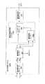
図2を参照すると、例である音声装置104がより詳細に示される。例である実施形態では、音声装置104は、プロセッサ202、第1マイクロホン106、第2マイクロホン108、音声処理システム204及び出力装置206を有する音声受信装置である。音声装置104は、音声装置104の動作に必要な更なる構成要素(示されていない)を有してもよい。音声処理システム204は、図3に関連してより詳細に議論される。 Referring to FIG. 2, an
例である実施形態では、第1及び第2マイクロホン106及び108は、それらの間のエネルギー・レベルの差を考慮に入れるために、間隔を離して配置される。マイクロホン106及び108により受信されると、音響信号は、電気信号(つまり、第1電気信号及び第2電気信号)へと変換されてもよい。幾つかの実施形態によると、これらの電気信号自体は、処理のため、アナログデジタル変換器(示されない)によりデジタル信号に変換されてもよい。音響信号を区別するために、第1マイクロホン106により受信された音響信号は、本願明細書では第1音響信号として参照され、第2マイクロホン108により受信された音響信号は、本願明細書では第2音響信号として参照される。 In an exemplary embodiment, the first and
出力装置206は、ユーザに音声出力を提供する如何なる装置であってよい。たとえば、出力装置206は、ヘッドセット又はハンドセットのイヤホン、又は会議装置のスピーカを有してもよい。 The
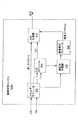
図3は、本発明のある実施形態による例である音声処理システム204aの詳細なブロック図である。例である実施形態では、音声処理システム204aは、メモリ装置内で実施される。図3の音声処理システム204aは、スプレッド・マイクロホン・アレイを有する実施形態で利用されてもよい。 FIG. 3 is a detailed block diagram of an exemplary
実際には、第1及び第2マイクロホン106及び108で受信された音響信号は、電気信号に変換され、周波数分析モジュール302を通じて処理される。ある実施形態では、周波数分析モジュール302は、音響信号を取得し、フィルタ・バンクによってシミュレートされた蝸牛(つまり、蝸牛領域)の周波数分析を模倣する。ある例では、周波数分析モジュール302は、音響信号を周波数サブバンドに分割する。サブバンドは、フィルタの帯域幅が周波数分析モジュール302により受信された信号の帯域幅よりも狭いときの入力信号に対するフィルタリング動作の結果である。或いは、短時間フーリエ変換(STFT)、サブバンド・フィルタ・バンク、変調複素重複変換、蝸牛モデル、ウェーブレット等のような他のフィルタも周波数分析及び合成に用いられうる。ほとんどの音(例えば、音響信号)は、複雑であり、1つ以上の周波数を有しているので、音響信号のサブバンド分析は、あるフレーム(例えば所定の時間期間)内の複雑な音響信号の中に、どんな個々の周波数が存在しているかを決定する。ある実施形態によると、そのフレームは、8msの長さである。別の実施形態は、他のフレーム長を利用してもよい。また、フレームを全く用いなくてもよい。その結果は、高速蝸牛変換(FCT)領域内にサブバンド信号を有してもよい。 In practice, the acoustic signals received by the first and
サブバンド信号が決定されると、該サブバンド信号は、雑音除去エンジン304へ転送される。例である雑音除去エンジン304は、各サブバンドの第1音響信号から雑音成分を適応して除去するように構成される。このように、雑音除去エンジン304の出力は、雑音が除去されたサブバンド信号を有する雑音が除去された信号である。雑音除去エンジン304は、図7A及び図7Bに関してより詳細に議論される。留意すべき点は、雑音が除去されたサブバンド信号は、会話音声又は非会話音声(例えば、音楽)である所望の音声を有してもよいことである。雑音除去エンジン304の結果は、ユーザへの出力であってよく、又は更なる雑音抑制システム(例えば、雑音抑制エンジン306)を通じて処理されてもよい。説明を目的として、本発明の実施形態は、雑音除去エンジン304の出力が、更なる雑音抑制システムを通じて処理される実施形態を議論する。 Once the subband signal is determined, the subband signal is forwarded to the
第2音響信号のサブバンド信号と共に雑音が除去されたサブバンド信号は、次に雑音抑制エンジン306aへと供給される。例である実施形態によると、雑音抑制エンジン306aは、雑音が除去された会話音声信号に残っている雑音成分を更に低減させるために、雑音が除去されたサブバンド信号に適用されるべきゲインマスクを生成する。雑音抑制エンジン306aは、以下の図4に関してより詳細に議論される。 The subband signal from which noise is removed together with the subband signal of the second acoustic signal is then supplied to the
雑音抑制エンジン306aによって決定されたゲインマスクは、次にマスキング・モジュール308において雑音が除去された信号に適用されてもよい。従って、各ゲインマスクは、マスクされた周波数サブバンドを生成するために、関連する雑音が除去された周波数サブバンドに適用されうる。図3に示されたように、乗法性雑音抑制システム312aは、雑音抑制エンジン306a及びマスキング・モジュール308を有する。 The gain mask determined by the
次に、マスクされた周波数サブバンドは、蝸牛領域から時間領域へと変換して戻される。この変換は、周波数合成モジュール310において、マスクされた周波数サブバンドを取得すること及び蝸牛チャネルの位相シフトされた信号と足し合わせることを有してもよい。或いは、この変換は、周波数合成モジュール310において、マスクされた周波数サブバンドを取得すること及び蝸牛チャネルの逆周波数とマスクされた周波数サブバンドを掛け合わせることを有してもよい。変換が完了すると、合成された音響信号がユーザへと出力されてもよい。 The masked frequency subband is then transformed back from the cochlea domain to the time domain. This transformation may include obtaining a masked frequency subband and summing with the phase-shifted signal of the cochlea channel at the
図4を参照すると、図3の雑音抑制エンジン306aが示される。例である雑音抑制エンジン306aは、エネルギー・モジュール402、マイクロホン間レベル差(ILD)モジュール404、適応型分類器406、雑音推定モジュール408及び適応型高機能抑制(AIS)生成器410を有する。留意すべき点は、雑音抑制エンジン306aは例であり、引用されることによりに援用される米国特許出願番号11/343524に示され記載されているようなモジュールの他の組み合わせを有してもよいことである。 Referring to FIG. 4, the
本発明の例である実施形態によると、雑音が除去された信号内の雑音を抑制し、会話音声を強めるために、AIS生成器410は、時間的及び周波数的に変動するゲイン、又はマスキング・モジュール308で用いられるゲインマスクを得る。しかしながら、ゲインマスクを得るために、AIS生成器410には特定の入力が必要となる。これらの入力は、雑音のパワー・スペクトル密度(つまり、雑音スペクトル)、雑音が除去された信号のパワー・スペクトル密度(本願明細書では第1スペクトルとして参照される)及びマイクロホン間レベル差(ILD)を有する。 According to an exemplary embodiment of the present invention, to suppress noise in the denoised signal and enhance speech speech, the
例である実施形態によると、雑音除去エンジン304の結果生じる雑音が除去された信号(c’(k))及び第2音響信号(f’(k))は、音響信号の各周波数帯に対するある時間間隔中のエネルギー/パワー推定値(つまり、パワー推定値)を計算するエネルギー・モジュール402へ転送される。図7Bに示すように、f’(k)は、状況に応じてf(k)と等しくてもよい。その結果、全周波数帯域に渡る第1スペクトル(つまり、雑音が除去された信号のパワー・スペクトル密度)は、エネルギー・モジュール402によって決定されてもよい。この第1スペクトルは、AIS生成器410及びILDモジュール404に供給されてもよい(本願明細書で更に議論される)。同様に、エネルギー・モジュール402は、全周波数帯域に渡る第2スペクトル(つまり、第2音響信号のパワー・スペクトル密度)も決定する。第2スペクトルも、ILDモジュール404に供給される。パワー推定値及びパワー・スペクトルの計算に関しての更なる詳細は、継続中の米国特許出願番号11/343524及び継続中の米国特許出願番号11/699732から分かる。これらの米国特許出願は参照されることにより本願明細書に援用される。 According to an example embodiment, the noise-removed signal (c ′ (k)) and the second acoustic signal (f ′ (k)) resulting from the
2つのマイクロホンの実施形態では、パワー・スペクトルは、第1及び第2マイクロホン106及び108間のエネルギー比を決定するために、マイクロホン間レベル差(ILD)モジュール404によって用いられる。例である実施形態では、ILDは、時間的及び周波数的に変動するILDであってもよい。第1及び第2マイクロホン106及び108は特定の方向に指向性があってもよいため、会話音声が活発なときはあるレベル差が生じ、雑音が活発なときは別のレベル差が生じうる。ILDは、次に、適応型分類器406及びAIS生成器410に転送される。ILDを計算するための実施形態に関しての更なる詳細は、継続中の米国特許出願番号11/343524及び継続中の米国特許出願番号11/699732から分かる。別の実施形態では、第1及び第2マイクロホン106及び108間の別の形式のILD又はエネルギー差が利用されてもよい。例えば、第1及び第2マイクロホン106及び108のエネルギー比が用いられてもよい。留意すべき点は、代替の実施形態が適応型分類及び雑音抑制(つまり、ゲインマスク計算)にILD以外のものを用いてもよいことである。例えば、雑音下限閾値が使われてもよい。また、ILDの利用への参照は、別のものにも適用可能であると考えられうる。例である適応型分類器406は、各フレームにおける各周波数帯の音響信号において、雑音及び混乱させるもの(例えば、負のILDを有する音源)を会話音声と区別するよう構成される。特徴(例えば、会話音声、雑音及び混乱させるもの)は、変化し、環境内の音響条件に依存するので、適応型分類器406は適応できると考えられる。例えば、ある状況で会話音声を示すILDは、別の状況では雑音を示しうる。従って、適応型分類器406は、ILDに基づいて分類境界を調整してもよい。 In the two microphone embodiment, the power spectrum is used by the inter-microphone level difference (ILD)
例である実施形態によると、適応型分類器406は、雑音及び混乱させるものを会話音声と区別し、雑音推定値を導き出す雑音推定モジュール408へ、結果を供給する。最初に、適応型分類器406は、各周波数におけるチャネル間の最大エネルギーを決定してもよい。各周波数のローカルILDもまた決定される。グローバルILDは、エネルギーをローカルILDに適用することによって計算されてもよい。新たに計算されたグローバルILDに基づいて、移動平均グローバルILD及び/又はILD観測のための移動平均及び分散(つまり、グローバル・クラスタ)が更新されてもよい。次に、フレーム・タイプが、グローバル・クラスタに対するグローバルILDの位置に基づき分類されてもよい。フレーム・タイプは、音源、背景騒音及び混乱させるものを有してもよい。 According to an example embodiment,
フレーム・タイプが決められると、適応型分類器406は、音源、背景騒音及び混乱させるものに対するグローバル平均の移動平均及び分散(つまり、クラスタ)を更新してもよい。ある例では、フレームが音源、背景騒音又は混乱させるものとして分類された場合、対応するグローバル・クラスタは活動的であると考えられ、グローバルILDの方へ動かされる。フレーム・タイプが一致しないグローバルな音源、背景騒音又は混乱させるもののグローバル・クラスタは、非活動的であると考えられる。所定の期間の間、非活動的なままの音源及び混乱させるもののグローバル・クラスタは、背景騒音のグローバル・クラスタの方へ移動しうる。背景騒音のグローバル・クラスタが所定の期間の間、非活動的なままの場合、背景騒音のグローバル・クラスタは、グローバル平均へと移動する。 Once the frame type is determined, the
フレーム・タイプが決められると、適応型分類器406は、音源、背景騒音及び混乱させるものに対するローカル平均の移動平均及び分散(つまり、クラスタ)も更新してもよい。ローカルの活動的及び非活動的クラスタを更新する処理は、グローバルの活動的及び非活動的クラスタを更新する処理と同様である。 Once the frame type is determined, the
音源及び背景騒音のクラスタの位置に基づき、エネルギー・スペクトル内の点は、音源又は雑音として分類される。この結果は、雑音推定モジュール408へと渡される。 Based on the location of the source and background noise clusters, the points in the energy spectrum are classified as source or noise. This result is passed to the
別の実施形態では、適応型分類器406の例は、最小統計量推定器を用いて、各周波数帯の最小ILDを追跡するものを有する。分類の閾は、各帯域の最小ILDより固定値(例えば、3dB)だけ上に置かれてもよい。或いは、閾値は、各帯域において観測されたILD値の直近の観測範囲に基づき、各帯域の最小ILDから可変の距離だけ上に置かれてもよい。例えば、観測されたILDの範囲が6dBを超えていた場合、ある特定の期間(例えば、2秒)に各帯域で観測される最小ILDと最大ILDの中ほどになるように、閾値が置かれうる。適応型分類器は、更に2007年7月6日出願の米国非仮出願番号11/825563、発明の名称「System and Method for Adaptive Intelligent Noise Supression」で議論されている。該出願は参照されることにより本願明細書に援用される。 In another embodiment, an example of
例である実施形態では、雑音推定は、第1マイクロホン106からの音響信号及び適用型分類器406からの結果に基づく。例である雑音推定モジュール408は、雑音推定値を生成する。本発明のある実施形態により、雑音推定値は、以下の式で数学的に近似されうる要素である。 In an exemplary embodiment, the noise estimate is based on the acoustic signal from the

上述の式中のλ1(t,ω)は、ILDモジュール404によって近似されたILDから以下のように導き出されうる。Λ1 (t, ω) in the above equation can be derived from the ILD approximated by the
AIS生成器410は、エネルギー・モジュール402から第1スペクトルの会話音声エネルギーを受け取る。この第1スペクトルは、雑音除去エンジン304による処理の後でも、幾つかの残余雑音も有しうる。AIS生成器410は、雑音推定モジュール408から雑音スペクトルも受け取ってよい。これらの入力とILDモジュール404からの任意のILDに基づき、会話音声スペクトルが推測されてもよい。ある実施形態では、会話音声スペクトルは、第1スペクトルのパワー推定値から雑音スペクトルの雑音推定値を減算することによって推測される。次に、AIS生成器410は、第1音響信号に適用するゲインマスクを決定してもよい。適応型分類器は、更に2007年7月6日出願の米国特許出願番号11/825563、発明の名称「System and Method for Adaptive Intelligent Noise Supression」から分かる。該出願は参照されることにより本願明細書に援用される。例である実施形態では、AIS生成器410からの時間及び周波数に依存するゲインマスク出力は、音声損失歪みを抑制する一方で、雑音抑制を最大化する。 The
留意すべき点は、この雑音抑制エンジン306aのシステム・アーキテクチャは例であるということである。別の実施形態は、更なる構成要素、少ない構成要素又は同じ数の構成要素を有してもよい。また、本発明の実施形態の範囲に包含される。雑音抑制エンジン306aの種々のモジュールは、1つのモジュールに結合されてもよい。例えば、ILDモジュール404の機能は、エネルギー・モジュール304の機能に結合されてもよい。 It should be noted that the system architecture of this
図5を参照すると、代替の音声処理システム204bの詳細なブロック図が示される。図3の音声処理システム204aとは対照的に、図5の音声処理システム204bは、クローズ・マイクロホン・アレイを有する実施形態に利用されてもよい。周波数分析モジュール302、マスキング・モジュール308及び周波数合成モジュール310の機能は、図3の音声処理システム204aに関して説明されたものと同一である。よって、詳細には議論しない。 Referring to FIG. 5, a detailed block diagram of an alternative
周波数分析モジュール302によって決定されたサブバンド信号は、雑音除去エンジン304及びアレイ処理エンジン502へと転送されてもよい。例である雑音除去エンジン304は、各サブバンドの第1音響信号から雑音成分を適応して除去するように構成される。このように、雑音除去エンジン304の出力は、雑音が除去されたサブバンド信号を有する雑音が除去された信号である。本実施形態では、雑音除去エンジン304は、雑音抑制エンジン306aに対しヌル処理(NP)ゲインも供給する。NPゲインは、雑音が除去された信号からどれだけ多くの第1信号が除去されたかを示すエネルギー比を有する。第1信号が雑音で占められている場合、NPゲインは大きくなる。反対に、第1信号が会話音声で占められている場合、NPゲインはゼロに近くなる。雑音除去エンジン304は、以下の図7A及び図7Bに関してより詳細に議論される。 The subband signal determined by
例である実施形態では、アレイ処理エンジン502は、クローズ・マイクロホン・アレイ(例えば、第1及び第2マイクロホン106及び108)のために指向性パターン(つまり、合成された指向性マイクロホン応答)第1信号及び第2信号のサブバンド信号を適応して処理するように構成される。指向性パターンは、第1音響(サブバンド)信号に基づく前方を向いたカージオイド・パターン及び第2(サブバンド)音響信号に基づく後方を向いたカージオイド・パターンを有する。ある実施形態では、サブバンド信号は、後方を向いたカージオイド・パターンが音源102の方を向くように適応されてもよい。アレイ処理エンジン502の実装及び機能に関しての更なる詳細は、米国特許出願番号12/080115、発明の名称「System and Method for Providing Close−Microphone Array Noise Reduction」から分かる(適応型アレイ処理エンジンとして参照される。)。該出願は参照されることにより本願明細書に援用される。カージオイド信号(つまり、前方を向いたカージオイド・パターンを実装する信号及び後方を向いたカージオイド・パターンを実装する信号)は、次に、アレイ処理エンジン502によって、雑音抑制エンジン306bに供給される。 In an exemplary embodiment, the
雑音抑制エンジン306bは、カージオイド信号と共にNPゲインを受け取る。例である実施形態によると、雑音抑制エンジン306bは、雑音が除去された会話音声信号に残りうる雑音成分を更に低減するために、雑音除去エンジン304からの雑音が除去されたサブバンド信号に適用するためのゲインマスクを生成する。雑音抑制エンジン306bは、以下の図6に関してより詳細に議論される。
雑音抑制エンジン306bによって決定されたゲインマスクは、次にマスキング・モジュール308において雑音が除去された信号に適用されてもよい。従って、各ゲインマスクは、マスクされた周波数サブバンドを生成するために、関連する雑音が除去された周波数サブバンドに適用されうる。 The gain mask determined by the
次に、マスクされた周波数サブバンドは、周波数合成モジュール310により、蝸牛領域から時間領域へと変換して戻される。変換が完了すると、合成された音響信号がユーザへと出力されてもよい。図5に示されたように、乗法性雑音抑制システム312bは、アレイ処理エンジン502、雑音抑制エンジン306b及びマスキング・モジュール308を有する。 The masked frequency subband is then transformed back from the cochlear domain to the time domain by the
図6を参照すると、例である雑音抑制エンジン306bがより詳細に示されている。例である雑音抑制エンジン306bは、エネルギー・モジュール402、マイクロホン間レベル差(ILD)モジュール404、適応型分類器406、雑音推定モジュール408及び適応型高機能抑制(AIS)生成器410を有する。留意すべき点は、雑音抑制エンジン306bの種々のモジュールは、雑音抑制エンジン306aのモジュールと同様に機能することである。 Referring to FIG. 6, an example
例である実施形態によると、第1音響信号(c’’(k))及び第2音響信号(f’’(k))は、音響信号の各周波数帯に対するある時間間隔中のエネルギー/パワー推定値(つまり、パワー推定値)を計算するエネルギー・モジュール402によって受け取られる。その結果、全周波数帯域に渡る第1スペクトル(つまり、第1サブバンド信号のパワー・スペクトル密度)は、エネルギー・モジュール402によって決定されてもよい。この第1スペクトルは、AIS生成器410及びILDモジュール404に供給されてもよい。同様に、エネルギー・モジュール402は、全周波数帯域に渡る第2スペクトル(つまり、第2サブバンド信号のパワー・スペクトル密度)も決定する。第2スペクトルも、ILDモジュール404に供給される。パワー推定値及びパワー・スペクトルの計算に関しての更なる詳細は、継続中の米国特許出願番号11/343524及び継続中の米国特許出願番号11/699732から分かる。これらの米国特許出願は参照されることにより本願明細書に援用される。 According to an exemplary embodiment, the first acoustic signal (c ″ (k)) and the second acoustic signal (f ″ (k)) are energy / power during a time interval for each frequency band of the acoustic signal. Received by an
前に議論したように、パワー・スペクトルは、第1及び第2マイクロホン106及び108間のエネルギー差を決定するために、ILDモジュール404によって用いられてもよい。ILDは、次に、適応型分類器406及びAIS生成器410に転送されてもよい。代替の実施形態では、第1及び第2マイクロホン106及び108間の別の形式のILD又はエネルギー差が利用されてもよい。例えば、第1及び第2マイクロホン106及び108のエネルギー比が用いられてもよい。留意すべき点は、代替の実施形態が適応型分類及び雑音抑制(つまり、ゲインマスク計算)にILD以外のものを用いてもよいことである。例えば、雑音下限閾値が使われてもよい。また、ILDの利用への参照は、別のものにも適用可能であると考えられうる。 As previously discussed, the power spectrum may be used by the
例である適応型分類器406及び雑音推定モジュール408は、図4に基づき説明したのと同様な機能を実行する。つまり、適応型分類器は、雑音及び混乱させるものを会話音声と区別し、雑音推定値を引き出す雑音推定モジュール408へ、その結果を供給する。 The example
AIS生成器410は、エネルギー・モジュール402から第1スペクトルの会話音声エネルギーを受け取る。AIS生成器410は、雑音推定モジュール408から雑音スペクトルも受け取ってよい。これらの入力とILDモジュール404からの任意のILDに基づき、会話音声スペクトルが推測されてもよい。ある実施形態では、会話音声スペクトルは、第1スペクトルのパワー推定値から雑音スペクトルの雑音推定値を減算することによって推測される。また、AIS生成器410は、NPゲインを用いる。NPゲインは、第1音響信号に適用するゲインマスクを決定するために、信号が雑音抑制システム306b(つまり、乗法性マスク)に届いた時までにどれだけ多くの雑音がすでに除去されたかを示す。ある例では、NPゲインが増加するにつれて、入力の推定SNRが減少する。例である実施形態では、AIS生成器410からの時間及び周波数に依存するゲインマスク出力は、音声損失歪みを抑制する一方で、雑音抑制を最大化してもよい。 The
留意すべき点は、この雑音抑制エンジン306bのシステム・アーキテクチャは例であるということである。別の実施形態は、更なる構成要素、少ない構成要素又は同じ数の構成要素を有してもよい。また、本発明の実施形態の範囲に包含される。 It should be noted that the system architecture of this
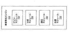
図7Aは例である雑音除去エンジン304のブロック図である。例である雑音除去エンジン304は、減算処理を用いて雑音を抑制するよう構成されている。雑音除去エンジン304は、第1の分岐で、まず、第1信号から所望の成分(例えば、所望の会話音声成分)を減算することによって、雑音が除去された信号を決定し、従って雑音成分を生じてもよい。次に、第2の分岐で、第1信号から雑音成分を除去するために、適応が実行されてもよい。例である実施形態では、雑音除去エンジン304は、ゲイン・モジュール702、分析モジュール704、適応モジュール706及び信号減算を実行するよう構成された少なくとも1つの加算モジュール708を有する。種々のモジュール702−708の機能は、図7Aに関して議論される。また、図7Bに関して動作中のところが更に示される。 FIG. 7A is a block diagram of an exemplary
図7Aを参照すると、例であるゲイン・モジュール702は、雑音除去エンジン304によって用いられる種々のゲインを決定するよう構成される。本実施形態の目的のために、これらのゲインは、エネルギー比を表す。第1の分岐で、どれだけの量の所望の成分が第1信号から除去されているかを示す基準エネルギー比(g1)が決められてもよい。第2の分岐で、雑音除去エンジン304の出力の際、どれだけの量のエネルギーが第1の分岐の結果から低減されたかを示す予測エネルギー比(g2)が決められてもよい。更に、エネルギー比(つまり、NPゲイン)は、雑音除去エンジン304によって第1信号からどれだけの量の雑音が除去されたかを示すエネルギー比を表すように決められてもよい。前に議論したように、NPゲインは、ゲインマスクを調整するために、クローズ・マイクロホンの実施形態において、AIS生成器410によって用いられてもよい。With reference to FIG. 7A, an
例である分析モジュール704は、雑音除去エンジン304の第1の分岐において分析を実行するよう構成される。一方、例である適用モジュール306は、雑音除去エンジン304の第2の分岐において適応を実行するよう構成されている。 The
図7bを参照すると、雑音除去エンジン304の動作を図示した概略図が示される。第1マイクロホン信号のサブバンド信号c(k)及び第2マイクロホン信号のサブバンド信号f(k)は、雑音除去エンジン304によって受け取られる。ここで、kは、離散時間又はサンプル・インデックスを表す。c(k)は、会話音声信号s(k)及び雑音信号n(k)の重ね合わせを表す。f(k)は、複素数の係数σによりスケーリングされた会話音声信号s(k)及び複素数の係数νによりスケーリングされた雑音信号n(k)の重ね合わせとしてモデル化されている。νは、どれだけの量の第1信号中の雑音が、第2信号の中にあるかを表す。例である実施形態では、雑音の音源は動的でありうるので、νは未知数である。 Referring to FIG. 7b, a schematic diagram illustrating the operation of the
例である実施形態では、σは、会話音声の場所(例えば、音声源の場所)を表す固定係数である。例である実施形態に従って、σは較正を通じて決定されてよい。1カ所以上に基づきキャリブレートすることによって、許容値は、較正に含まれうる。クローズ・マイクロホンでは、σの大きさは1に近い。スプレッド・マイクロホンでは、σの大きさは、話者の口に対して音声装置102がどこに置かれるかに依存する。σの大きさ及び位相は、それぞれのサブバンド(例えば、蝸牛タップ)によって表される周波数での話者の口の位置に対するチャネル間クロス・スペクトルを表す。雑音除去エンジン304は、σが何であるかを知っているので、分析モジュール704は、会話音声成分σs(k)(つまり、所望の成分)を第2信号から除去するために、σを第1信号(つまり、σ(s(k)+ν(k)))に適用し、第2信号(つまり、σs(k)+ν(k))からその結果を減算する。その結果、加算モジュール708から雑音成分が出る。会話音声がない実施形態では、αは、およそ1/(ν−σ)であり、適用モジュール706は自由に適応してもよい。 In the exemplary embodiment, σ is a fixed factor that represents the location of the conversational voice (eg, the location of the audio source). According to an exemplary embodiment, σ may be determined through calibration. By calibrating based on one or more locations, tolerances can be included in the calibration. In the closed microphone, the magnitude of σ is close to 1. In a spread microphone, the magnitude of σ depends on where the audio device 102 is placed relative to the speaker's mouth. The magnitude and phase of σ represent the inter-channel cross spectrum for the position of the speaker's mouth at the frequency represented by the respective subband (eg, cochlear tap). Since the
話者の口の位置がσによって適切に表されているならば、f(k)−σc(k)=(ν―σ)n(k)である。この方程式は、適用モジュール706(適用モジュール706は、順々に、適用係数α(k)を適用する)に与えられる加算モジュール708の出力信号が、σ(例えば、所望の会話音声信号)によって表される位置から生じる信号を欠いているということを示している。例である実施形態では、分析モジュール704は、σを第2信号f(k)に適用し、c(k)からその結果を減算する。加算モジュール708からの残りの信号(本願明細書では「雑音成分信号」として参照されている)は、第2の分岐において除去されてもよい。 If the position of the speaker's mouth is appropriately represented by σ, then f (k) −σc (k) = (ν−σ) n (k). This equation is expressed in terms of the output signal of the summing
第1信号が会話場所(σで表される)でない音源102によって占められているとき、適応モジュール706は、適応してもよい。第1信号がσで表される会話場所から生ずる信号によって占められているとき、適応は、機能停止されてもよい。例である実施形態では、信号c(k)から雑音成分n(k)を除去するために、適用モジュール706は、一般的な最小二乗法の1つを用いて適応してもよい。ある実施形態によると、係数は、あるフレーム・レートにおいて更新されてもよい。 The
n(k)が白色雑音であり、s(k)とn(k)の相互相関が、あるフレーム内でゼロである実施形態では、適応は、完全に除去されている雑音n(k)及び完全に影響を受けていない会話音声s(k)を有する全てのフレームで生じてもよい。しかしながら、特にフレーム・サイズが短い場合は、実際にはこれらの条件が満たされることは生じ難い。このように、望ましくは、適応において制約が適用される。例である実施形態では、適用係数α(k)は、基準エネルギー比g1及び予測エネルギー比g2が以下の条件を満たすとき、タップ毎/フレーム毎に基づき更新されてもよい。In embodiments where n (k) is white noise and the cross-correlation between s (k) and n (k) is zero within a frame, the adaptation is the noise n (k) that has been completely removed and It may occur in every frame that has a conversation voice s (k) that is not completely affected. However, in particular, it is unlikely that these conditions will be met, especially when the frame size is short. Thus, preferably constraints are applied in adaptation. In the example embodiment, the application factor α (k) may be updated on a tap-by-tap / frame-by-frame basis when the reference energy ratio g1 and the predicted energy ratio g2 satisfy the following conditions.
例えば、
For example,
前の3つの方程式から、以下の式が得られる。 From the previous three equations, the following equation is obtained:
係数γは、αの適応と非適応の境界を定義するために選ばれてもよい。マイクロホン106及び108の間の直線に対して90度の角度で遠距離場にある実施形態では、この実施形態では、信号は、マイクロホン106及び108の間で同じパワーとゼロの位相シフトを有してもよい(例えば、ν=1)。SNR=1ならば、γ2|ν−σ|4=2であり、これは次式と等価である。The coefficient γ may be chosen to define the boundary between α adaptation and non-adaptation. In an embodiment that is in the far field at a 90 degree angle to the straight line between the
図8は、音声装置の雑音抑制の例である方法のフローチャート800である。段階802で、音声信号は音声装置102により受信される。例である実施形態では、複数のマイクロホン(例えば、第1及び第2マイクロホン106及び108)が、音声信号を受信する。この複数のマイクロホンは、クローズ・マイクロホン・アレイ又はスプレッド・マイクロホン・アレイを有する。 FIG. 8 is a
段階804で、第1及び第2音響信号の周波数分析が実行されてもよい。ある実施形態では、周波数分析モジュール302は、第1及び第2音響信号の周波数サブバンドを決定するために、フィルタ・バンクを利用する。 In
段階806で、雑音除去処理が実行される。段階806は、図9に関して、更に詳細に議論される。 In
次に段階808で、雑音抑制処理が実行されてもよい。ある実施形態では、雑音抑制処理は、最初に、第1信号又は雑音が除去された信号、並びに第2信号のエネルギー・スペクトルを計算する。次に、2つの信号間のエネルギー差が決定されてもよい。続いて、会話音声及び雑音成分が、ある実施形態に従って適応して分類されてもよい。次に、雑音スペクトルが決定されてもよい。ある実施形態では、雑音推定値は、雑音成分に基づいてもよい。雑音推定値に基づき、ゲインマスクが、適応して決定されてもよい。 Next, in
次に段階810で、ゲインマスクが適用されてもよい。ある実施形態では、ゲインマスクは、サブバンド信号毎にマスキング・モジュール308によって適用されてもよい。幾つかの実施形態では、ゲインマスクは、雑音が除去された信号に適用されてもよい。次に段階812で、サブバンド信号は、出力を生成するために合成されてもよい。ある実施形態では、サブバンド信号は、周波数領域から時間領域へ変換して戻されてもよい。変換されると、段階814で、音声信号はユーザへと出力されてもよい。出力は、スピーカ、イヤホン又は他の類似の装置を介してもよい。 Next, at
図9を参照すると、雑音除去処理(段階806)を実行する例である方法のフローチャートが示される。段階902で、周波数が分析された信号(例えば、周波数サブバンド信号又は第1信号)が雑音除去エンジン304によって受け取られる。第1音響信号は、c(k)=s(k)+n(k)として表されてもよい。ここで、s(k)は、所望の信号(例えば、会話音声信号)を表し、n(k)は、雑音信号を表す。第2の周波数を分析された信号(例えば、第2信号)は、f(k)=σs(k)+νn(k)で表される。 Referring to FIG. 9, a flowchart of an exemplary method for performing a denoising process (stage 806) is shown. In
段階904で、σは、分析モジュール704によって第1信号に適用されてもよい。次に段階906で、第1信号へのσの適用結果は、加算モジュール708によって第2信号から減算されてもよい。この結果は、雑音成分信号を有する。 In
段階908で、ゲイン・モジュール702によって、ゲインが計算されてもよい。これらのゲインは、種々の信号のエネルギー比を表す。第1の分岐で、どれだけの量の所望の成分が第1信号から除去されているかを示す基準エネルギー比(g1)が決められてもよい。第2の分岐で、雑音除去エンジン304の出力の際、どれだけの量のエネルギーが第1の分岐の結果から低減されたかを示す予測エネルギー比(g2)が決められてもよい。In
段階910で、αが適用されるべきかどうかの決定がなされる。ある実施形態に基づき、γ2|ν−σ|4>SNR2+SNR4が真ならば、段階912で、αの適応が実行されてもよい。しかしながら、この方程式が真でなければ、αは適応されず、段階914で機能停止される。At
段階916で、適応されるか否かに拘わらず、雑音成分信号は加算モジュール708によって第1信号から除去される。その結果は、雑音が除去された信号である。幾つかの実施形態では、雑音が除去された信号は、乗法性雑音抑制処理による更なる雑音抑制処理のために、雑音抑制エンジン306に供給される。別の実施形態では、雑音が除去された信号は、更なる雑音抑制処理なしに、ユーザへ出力されてもよい。留意すべき点は、1つより多い加算モジュール708が提供されてもよいことである(例えば、雑音除去エンジン304の各分岐に対して1つ)。 At
段階918で、NPゲインが計算されてもよい。NPゲインは、雑音が除去された信号からどれだけ多くの第1信号が除去されたかを示すエネルギー比を有する。留意すべき点は、段階918は、任意(例えば、クローズ・マイクロホン・システムの場合)であることである。 At
上述のモジュールは、機械可読媒体(例えば、コンピュータ可読媒体)のような記憶媒体に格納された命令を有してもよい。それらの命令は、プロセッサ202によって読み出され、実行されてもよい。命令の幾つかの例は、ソフトウェア、プログラム・コード及びファームウェアを含む。記憶媒体の幾つかの例は、メモリ装置及び集積回路を有する。命令は、プロセッサ202によって実行されるとき、プロセッサ202に本発明の実施形態に従って動作するよう指示するように動作可能である。当業者は、命令、プロセッサ及び記憶媒体に精通している。 The modules described above may have instructions stored on a storage medium such as a machine readable medium (eg, a computer readable medium). Those instructions may be read and executed by the processor 202. Some examples of instructions include software, program code, and firmware. Some examples of storage media include memory devices and integrated circuits. The instructions are operable to instruct the processor 202 to operate in accordance with embodiments of the present invention when executed by the processor 202. Those skilled in the art are familiar with instructions, processors, and storage media.
本発明は、例である実施形態を参照し上述された。本発明の広範な範囲から逸脱することなく、種々の変形がなされうること及び別の実施形態が使われうることは、当業者には明らかである。例えば、本願明細書で議論されたマイクロホン・アレイは、第1及び第2マイクロホン106及び108を有する。しかし、別の実施形態は、マイクロホン・アレイの中に更に多くのマイクロホンを利用することを意図してもよい。従って、例である実施形態についてのこれら及び他の変更は、本発明に含まれていると意図される。 The present invention has been described above with reference to exemplary embodiments. It will be apparent to those skilled in the art that various modifications and other embodiments can be used without departing from the broad scope of the invention. For example, the microphone array discussed herein has first and
[関連出願の相互参照]
本出願は、2007年7月6日出願の米国特許出願番号11/825563、発明の名称「System and Method for Adaptive Intelligent Noise Suppression」、2008年3月31日出願の米国特許出願番号12/080115、発明の名称「System and Method for Providing Close−Microphone Array Noise Reduction」に関連する。両出願は参照されることにより本願明細書に援用される。[Cross-reference of related applications]
This application is a U.S. Patent Application No. 11/825563 filed on Jul. 6, 2007, entitled "System and Method for Adaptive Intelligent Noise Suppression", U.S. Patent Application No. 12/080115, filed March 31, 2008, Relevant to the title of the invention “System and Method for Providing Close-Microphone Array Noise Reduction”. Both applications are hereby incorporated by reference.
本出願は、2006年1月30日出願の米国特許出願番号11/343524、発明の名称「System and Method for Utilizing Inter−Microphone Level Differences for Speech Enhancement」、2007年1月29日出願の米国特許出願番号11/699732、発明の名称「System and Method for Utilizing Omni−Directional Microphones for Speech Enhancement」に関連する。両出願は参照されることにより本願明細書に援用される。 This application is filed on US Patent Application No. 11/343524, filed January 30, 2006, entitled "System and Method for Customizing Inter-Microphone Level Differences for Speech Enhancement", US Patent Application on January 29, 2007. No. 11/69972, relating to the title of the invention “System and Method for Customizing Omni-Directional Microphones for Speech Enhancement”. Both applications are hereby incorporated by reference.
Claims (18)
Translated fromJapanese少なくとも第1及び第2音響信号を受信する段階、
周波数分析を用いて前記第1及び第2の音響信号を周波数サブバンドに分ける段階、
所望の信号成分を生成するために、音源の場所を表す係数を前記第1音響信号に適用する段階、
雑音成分信号を得るために、前記第2音響信号から前記所望の信号成分を減算する段階、
前記所望の信号成分及び前記雑音成分信号に関連する少なくとも1つのエネルギー比の第1の決定を行う段階、
前記少なくとも1つのエネルギー比に基づき、前記雑音成分信号を調整するか否かの第2の決定を行う段階、
前記第2の決定に基づき、前記雑音成分信号を調整する段階、
雑音の除去された信号を生成するために、前記第1音響信号から前記雑音成分信号を減算する段階、
前記雑音の除去された信号を出力する段階、
を有する方法。A method of suppressing noise,
Receiving at least first and second acoustic signals;
Separating the first and second acoustic signals into frequency subbands using frequency analysis;
Applying a coefficient representing the location of a sound source to the first acoustic signal to generate a desired signal component;
Subtracting the desired signal component from the second acoustic signal to obtain a noise component signal;
Making a first determination of at least one energy ratio associated with the desired signal component and the noise component signal;
Making a second determination of whether to adjust the noise component signal based on the at least one energy ratio;
Adjusting the noise component signal based on the second determination;
Subtracting the noise component signal from the first acoustic signal to generate a noise-free signal;
Outputting the denoised signal;
Having a method.
ことを特徴とする請求項1に記載の方法。The at least one energy ratio has a reference energy ratio and a predicted energy ratio;
The method according to claim 1.
を更に有する請求項2に記載の方法。Adapting an adaptation coefficient applied to the noise component signal when the predicted energy ratio is greater than the reference energy ratio;
The method of claim 2 further comprising:
を更に有する請求項2に記載の方法。Fixing an adaptation coefficient applied to the noise component signal when the predicted energy ratio is smaller than the reference energy ratio;
The method of claim 2 further comprising:
を更に有する請求項1に記載の方法。Determining an NP gain based on at least one energy ratio indicating how much of the first acoustic signal has been removed from the denoised signal;
The method of claim 1 further comprising:
を更に有する請求項5に記載の方法。Providing the NP gain to a multiplicative noise suppression system;
The method of claim 5 further comprising:
ことを特徴とする請求項1に記載の方法。Outputting the denoised signal comprises outputting the denoised signal to a multiplicative noise suppression system;
The method according to claim 1.
ことを特徴とする請求項7に記載の方法。The multiplicationmethod noise suppression system generates the gain mask based on at least filtered signal of said noise,
The method according to claim 7.
を更に有する請求項8に記載の方法。Applying the gain mask to the denoised signal to generate an audio output signal;
9. The method of claim 8, further comprising:
少なくとも第1及び第2音響信号を受信するよう構成されたマイクロホン・アレイ、
前記第1及び第2の音響信号を周波数サブバンドに分け、音源の場所を表す係数を前記第1音響信号に適用し、所望の信号成分を生成する周波数分析モジュールであって、前記所望の信号成分は、雑音成分信号を得るために前記第2の音響信号から減算さる、周波数分析モジュール、
前記所望の信号成分及び前記雑音成分信号に関連する少なくとも1つのエネルギー比の第1の決定を行うよう構成されたゲイン・モジュール、
前記少なくとも1つのエネルギー比に基づき、前記雑音成分信号を調整するか否かの第2の決定を行うよう構成され、前記第2の決定に基づき前記雑音成分信号を調整するよう更に構成された適応モジュール、
雑音の除去された信号を生成するために、前記第2音響信号から前記所望の信号成分を減算し、前記第1音響信号から前記雑音成分信号を減算するよう構成された少なくとも1つの加算モジュール、
を有するシステム。A system for suppressing noise,
A microphone array configured to receive at least first and second acoustic signals;
A frequency analysis module that divides the first and second acoustic signals into frequency subbands and applies a coefficient representing the location of a sound source to the first acoustic signal to generate a desired signal component, the desired signal A frequency analysis module, wherein a component is subtracted from the second acoustic signal to obtain a noise component signal;
A gain module configured to make a first determination of at least one energy ratio associated with the desired signal component and the noise component signal;
An adaptation configured to make a second determination whether to adjust the noise component signal based on the at least one energy ratio, and further configured to adjust the noise component signal based on the second determination module,
At least one addition module configured to subtract the desired signal component from the second acoustic signal and subtract the noise component signal from the first acoustic signal to generate a noise-free signal;
Having a system.
ことを特徴とする請求項10に記載のシステム。The at least one energy ratio has a reference energy ratio and a predicted energy ratio;
The system according to claim 10.
ことを特徴とする請求項11に記載のシステム。The adaptation module is configured to adapt an adaptation factor applied to the noise component signal when the predicted energy ratio is greater than the reference energy ratio;
The system according to claim 11.
ことを特徴とする請求項11に記載のシステム。The adaptation module is configured to fix an adaptation factor applied to the noise component signal when the predicted energy ratio is less than the reference energy ratio;
The system according to claim 11.
を更に有する請求項10に記載のシステム。A gain module configured to determine an NP gain based on at least one energy ratio indicating how much of the first acoustic signal has been removed from the denoised signal;
The system of claim 10 further comprising:
前記プログラムは命令を格納し、前記命令はコンピュータにより実行されると前記コンピュータに雑音除去処理を用いて雑音を抑制する方法のための命令を実行させ、
前記方法は、
少なくとも第1及び第2音響信号を受信する段階、
前記第1及び第2の音響信号を周波数サブバンドに分ける段階、
所望の信号成分を生成するために、音源の場所を表す係数を前記第1音響信号に適用する段階、
雑音成分信号を得るために、前記所望の信号成分を前記第2音響信号から減算する段階、
前記所望の信号成分及び前記雑音成分信号に関連する少なくとも1つのエネルギー比の第1の決定を行う段階、
前記少なくとも1つのエネルギー比に基づき、前記雑音成分信号を調整するか否かの第2の決定を行う段階、
前記第2の決定に基づき、前記雑音成分信号を調整する段階、
雑音の除去された信号を生成するために、前記雑音成分信号を前記第1音響信号から減算する段階、
前記雑音の除去された信号を出力する段階、
を有する、
ことを特徴とする機械可読記憶媒体。A machine-readablestorage medium having a program,
The programstoring instructions, the instructions instructionand theexecution for the method of suppressing the noise by using a noise removal processon the computer and executed by a computer,
The method
Receiving at least first and second acoustic signals;
Dividing the first and second acoustic signals into frequency subbands;
Applying a coefficient representing the location of a sound source to the first acoustic signal to generate a desired signal component;
Subtracting the desired signal component from the second acoustic signal to obtain a noise component signal;
Making a first determination of at least one energy ratio associated with the desired signal component and the noise component signal;
Making a second determination of whether to adjust the noise component signal based on the at least one energy ratio;
Adjusting the noise component signal based on the second determination;
Subtracting the noise component signal from the first acoustic signal to produce a noise-free signal;
Outputting the denoised signal;
Having
A machine-readablestorage medium.
ことを特徴とする請求項15に記載の機械可読記憶媒体。The at least one energy ratio has a reference energy ratio and a predicted energy ratio;
The machine-readablestorage medium according to claim 15.
前記予測エネルギー比が前記基準エネルギー比より大きいとき、前記雑音成分信号に適用される適応係数を適応する段階、
を更に有する、
ことを特徴とする請求項16に記載の機械可読記憶媒体。The method
Adapting an adaptation coefficient applied to the noise component signal when the predicted energy ratio is greater than the reference energy ratio;
Further having
The machine-readablestorage medium according to claim 16.
前記予測エネルギー比が前記基準エネルギー比より小さいとき、前記雑音成分信号に適用される適応係数を固定する段階、
を更に有する、
ことを特徴とする請求項16に記載の機械可読記憶媒体。The method
Fixing an adaptation coefficient applied to the noise component signal when the predicted energy ratio is smaller than the reference energy ratio;
Further having
The machine-readablestorage medium according to claim 16.
Applications Claiming Priority (3)
| Application Number | Priority Date | Filing Date | Title |
|---|---|---|---|
| US12/215,980US9185487B2 (en) | 2006-01-30 | 2008-06-30 | System and method for providing noise suppression utilizing null processing noise subtraction |
| US12/215,980 | 2008-06-30 | ||
| PCT/US2009/003813WO2010005493A1 (en) | 2008-06-30 | 2009-06-26 | System and method for providing noise suppression utilizing null processing noise subtraction |
Publications (2)
| Publication Number | Publication Date |
|---|---|
| JP2011527025A JP2011527025A (en) | 2011-10-20 |
| JP5762956B2true JP5762956B2 (en) | 2015-08-12 |
Family
ID=41447473
Family Applications (1)
| Application Number | Title | Priority Date | Filing Date |
|---|---|---|---|
| JP2011516313AExpired - Fee RelatedJP5762956B2 (en) | 2008-06-30 | 2009-06-26 | System and method for providing noise suppression utilizing nulling denoising |
Country Status (6)
| Country | Link |
|---|---|
| US (2) | US9185487B2 (en) |
| JP (1) | JP5762956B2 (en) |
| KR (1) | KR101610656B1 (en) |
| FI (1) | FI20100431A7 (en) |
| TW (1) | TWI488179B (en) |
| WO (1) | WO2010005493A1 (en) |
Cited By (6)
| Publication number | Priority date | Publication date | Assignee | Title |
|---|---|---|---|---|
| US9536540B2 (en) | 2013-07-19 | 2017-01-03 | Knowles Electronics, Llc | Speech signal separation and synthesis based on auditory scene analysis and speech modeling |
| US9558755B1 (en) | 2010-05-20 | 2017-01-31 | Knowles Electronics, Llc | Noise suppression assisted automatic speech recognition |
| US9640194B1 (en) | 2012-10-04 | 2017-05-02 | Knowles Electronics, Llc | Noise suppression for speech processing based on machine-learning mask estimation |
| US9799330B2 (en) | 2014-08-28 | 2017-10-24 | Knowles Electronics, Llc | Multi-sourced noise suppression |
| US9830899B1 (en) | 2006-05-25 | 2017-11-28 | Knowles Electronics, Llc | Adaptive noise cancellation |
| US10257611B2 (en) | 2016-05-02 | 2019-04-09 | Knowles Electronics, Llc | Stereo separation and directional suppression with omni-directional microphones |
Families Citing this family (82)
| Publication number | Priority date | Publication date | Assignee | Title |
|---|---|---|---|---|
| WO2007106399A2 (en) | 2006-03-10 | 2007-09-20 | Mh Acoustics, Llc | Noise-reducing directional microphone array |
| US8098844B2 (en)* | 2002-02-05 | 2012-01-17 | Mh Acoustics, Llc | Dual-microphone spatial noise suppression |
| US8345890B2 (en) | 2006-01-05 | 2013-01-01 | Audience, Inc. | System and method for utilizing inter-microphone level differences for speech enhancement |
| US8744844B2 (en) | 2007-07-06 | 2014-06-03 | Audience, Inc. | System and method for adaptive intelligent noise suppression |
| US8204252B1 (en) | 2006-10-10 | 2012-06-19 | Audience, Inc. | System and method for providing close microphone adaptive array processing |
| US8194880B2 (en) | 2006-01-30 | 2012-06-05 | Audience, Inc. | System and method for utilizing omni-directional microphones for speech enhancement |
| US9185487B2 (en) | 2006-01-30 | 2015-11-10 | Audience, Inc. | System and method for providing noise suppression utilizing null processing noise subtraction |
| US8849231B1 (en) | 2007-08-08 | 2014-09-30 | Audience, Inc. | System and method for adaptive power control |
| US8934641B2 (en) | 2006-05-25 | 2015-01-13 | Audience, Inc. | Systems and methods for reconstructing decomposed audio signals |
| US8150065B2 (en) | 2006-05-25 | 2012-04-03 | Audience, Inc. | System and method for processing an audio signal |
| US8204253B1 (en) | 2008-06-30 | 2012-06-19 | Audience, Inc. | Self calibration of audio device |
| US8259926B1 (en) | 2007-02-23 | 2012-09-04 | Audience, Inc. | System and method for 2-channel and 3-channel acoustic echo cancellation |
| US8189766B1 (en) | 2007-07-26 | 2012-05-29 | Audience, Inc. | System and method for blind subband acoustic echo cancellation postfiltering |
| US8180064B1 (en) | 2007-12-21 | 2012-05-15 | Audience, Inc. | System and method for providing voice equalization |
| US8143620B1 (en) | 2007-12-21 | 2012-03-27 | Audience, Inc. | System and method for adaptive classification of audio sources |
| US8194882B2 (en) | 2008-02-29 | 2012-06-05 | Audience, Inc. | System and method for providing single microphone noise suppression fallback |
| US8355511B2 (en) | 2008-03-18 | 2013-01-15 | Audience, Inc. | System and method for envelope-based acoustic echo cancellation |
| US8774423B1 (en) | 2008-06-30 | 2014-07-08 | Audience, Inc. | System and method for controlling adaptivity of signal modification using a phantom coefficient |
| US8521530B1 (en) | 2008-06-30 | 2013-08-27 | Audience, Inc. | System and method for enhancing a monaural audio signal |
| EP2368243B1 (en)* | 2008-12-19 | 2015-04-01 | Telefonaktiebolaget L M Ericsson (publ) | Methods and devices for improving the intelligibility of speech in a noisy environment |
| US9202456B2 (en)* | 2009-04-23 | 2015-12-01 | Qualcomm Incorporated | Systems, methods, apparatus, and computer-readable media for automatic control of active noise cancellation |
| US20100278354A1 (en)* | 2009-05-01 | 2010-11-04 | Fortemedia, Inc. | Voice recording method, digital processor and microphone array system |
| US20110096942A1 (en)* | 2009-10-23 | 2011-04-28 | Broadcom Corporation | Noise suppression system and method |
| US9210503B2 (en)* | 2009-12-02 | 2015-12-08 | Audience, Inc. | Audio zoom |
| US9838784B2 (en) | 2009-12-02 | 2017-12-05 | Knowles Electronics, Llc | Directional audio capture |
| US20110178800A1 (en)* | 2010-01-19 | 2011-07-21 | Lloyd Watts | Distortion Measurement for Noise Suppression System |
| US8718290B2 (en)* | 2010-01-26 | 2014-05-06 | Audience, Inc. | Adaptive noise reduction using level cues |
| US9008329B1 (en)* | 2010-01-26 | 2015-04-14 | Audience, Inc. | Noise reduction using multi-feature cluster tracker |
| US8473287B2 (en) | 2010-04-19 | 2013-06-25 | Audience, Inc. | Method for jointly optimizing noise reduction and voice quality in a mono or multi-microphone system |
| US8538035B2 (en) | 2010-04-29 | 2013-09-17 | Audience, Inc. | Multi-microphone robust noise suppression |
| US8798290B1 (en)* | 2010-04-21 | 2014-08-05 | Audience, Inc. | Systems and methods for adaptive signal equalization |
| US8781137B1 (en) | 2010-04-27 | 2014-07-15 | Audience, Inc. | Wind noise detection and suppression |
| US9378754B1 (en)* | 2010-04-28 | 2016-06-28 | Knowles Electronics, Llc | Adaptive spatial classifier for multi-microphone systems |
| US9245538B1 (en)* | 2010-05-20 | 2016-01-26 | Audience, Inc. | Bandwidth enhancement of speech signals assisted by noise reduction |
| US9053697B2 (en) | 2010-06-01 | 2015-06-09 | Qualcomm Incorporated | Systems, methods, devices, apparatus, and computer program products for audio equalization |
| US8447596B2 (en) | 2010-07-12 | 2013-05-21 | Audience, Inc. | Monaural noise suppression based on computational auditory scene analysis |
| US9772815B1 (en) | 2013-11-14 | 2017-09-26 | Knowles Electronics, Llc | Personalized operation of a mobile device using acoustic and non-acoustic information |
| US10353495B2 (en) | 2010-08-20 | 2019-07-16 | Knowles Electronics, Llc | Personalized operation of a mobile device using sensor signatures |
| US8682006B1 (en) | 2010-10-20 | 2014-03-25 | Audience, Inc. | Noise suppression based on null coherence |
| US8831937B2 (en)* | 2010-11-12 | 2014-09-09 | Audience, Inc. | Post-noise suppression processing to improve voice quality |
| CN103238182B (en) | 2010-12-15 | 2015-07-22 | 皇家飞利浦电子股份有限公司 | Noise reduction system with remote noise detector |
| RU2633107C2 (en) | 2012-12-21 | 2017-10-11 | Фраунхофер-Гезелльшафт Цур Фердерунг Дер Ангевандтен Форшунг Е.Ф. | Adding comfort noise for modeling background noise at low data transmission rates |
| US9117457B2 (en)* | 2013-02-28 | 2015-08-25 | Signal Processing, Inc. | Compact plug-in noise cancellation device |
| US10049685B2 (en) | 2013-03-12 | 2018-08-14 | Aaware, Inc. | Integrated sensor-array processor |
| US10204638B2 (en) | 2013-03-12 | 2019-02-12 | Aaware, Inc. | Integrated sensor-array processor |
| US9443529B2 (en) | 2013-03-12 | 2016-09-13 | Aawtend, Inc. | Integrated sensor-array processor |
| US20140278393A1 (en) | 2013-03-12 | 2014-09-18 | Motorola Mobility Llc | Apparatus and Method for Power Efficient Signal Conditioning for a Voice Recognition System |
| US20140270249A1 (en)* | 2013-03-12 | 2014-09-18 | Motorola Mobility Llc | Method and Apparatus for Estimating Variability of Background Noise for Noise Suppression |
| US9570087B2 (en) | 2013-03-15 | 2017-02-14 | Broadcom Corporation | Single channel suppression of interfering sources |
| US20180317019A1 (en) | 2013-05-23 | 2018-11-01 | Knowles Electronics, Llc | Acoustic activity detecting microphone |
| US9508345B1 (en) | 2013-09-24 | 2016-11-29 | Knowles Electronics, Llc | Continuous voice sensing |
| US10536773B2 (en)* | 2013-10-30 | 2020-01-14 | Cerence Operating Company | Methods and apparatus for selective microphone signal combining |
| US9781106B1 (en) | 2013-11-20 | 2017-10-03 | Knowles Electronics, Llc | Method for modeling user possession of mobile device for user authentication framework |
| US9953634B1 (en) | 2013-12-17 | 2018-04-24 | Knowles Electronics, Llc | Passive training for automatic speech recognition |
| US9437188B1 (en) | 2014-03-28 | 2016-09-06 | Knowles Electronics, Llc | Buffered reprocessing for multi-microphone automatic speech recognition assist |
| US9500739B2 (en) | 2014-03-28 | 2016-11-22 | Knowles Electronics, Llc | Estimating and tracking multiple attributes of multiple objects from multi-sensor data |
| US9807725B1 (en) | 2014-04-10 | 2017-10-31 | Knowles Electronics, Llc | Determining a spatial relationship between different user contexts |
| US10149047B2 (en)* | 2014-06-18 | 2018-12-04 | Cirrus Logic Inc. | Multi-aural MMSE analysis techniques for clarifying audio signals |
| CN107112025A (en) | 2014-09-12 | 2017-08-29 | 美商楼氏电子有限公司 | System and method for recovering speech components |
| US9712915B2 (en) | 2014-11-25 | 2017-07-18 | Knowles Electronics, Llc | Reference microphone for non-linear and time variant echo cancellation |
| DE112016000287T5 (en) | 2015-01-07 | 2017-10-05 | Knowles Electronics, Llc | Use of digital microphones for low power keyword detection and noise reduction |
| WO2016123560A1 (en) | 2015-01-30 | 2016-08-04 | Knowles Electronics, Llc | Contextual switching of microphones |
| WO2016135741A1 (en)* | 2015-02-26 | 2016-09-01 | Indian Institute Of Technology Bombay | A method and system for suppressing noise in speech signals in hearing aids and speech communication devices |
| US9401158B1 (en) | 2015-09-14 | 2016-07-26 | Knowles Electronics, Llc | Microphone signal fusion |
| US10403259B2 (en) | 2015-12-04 | 2019-09-03 | Knowles Electronics, Llc | Multi-microphone feedforward active noise cancellation |
| US9830930B2 (en) | 2015-12-30 | 2017-11-28 | Knowles Electronics, Llc | Voice-enhanced awareness mode |
| US9779716B2 (en) | 2015-12-30 | 2017-10-03 | Knowles Electronics, Llc | Occlusion reduction and active noise reduction based on seal quality |
| WO2017123814A1 (en) | 2016-01-14 | 2017-07-20 | Knowles Electronics, Llc | Systems and methods for assisting automatic speech recognition |
| WO2017127646A1 (en) | 2016-01-22 | 2017-07-27 | Knowles Electronics, Llc | Shared secret voice authentication |
| US9812149B2 (en) | 2016-01-28 | 2017-11-07 | Knowles Electronics, Llc | Methods and systems for providing consistency in noise reduction during speech and non-speech periods |
| US10378997B2 (en) | 2016-05-06 | 2019-08-13 | International Business Machines Corporation | Change detection using directional statistics |
| WO2018037643A1 (en)* | 2016-08-23 | 2018-03-01 | ソニー株式会社 | Information processing device, information processing method, and program |
| CN107026934B (en)* | 2016-10-27 | 2019-09-27 | 华为技术有限公司 | Sound source localization method and device |
| WO2018148095A1 (en) | 2017-02-13 | 2018-08-16 | Knowles Electronics, Llc | Soft-talk audio capture for mobile devices |
| US10468020B2 (en)* | 2017-06-06 | 2019-11-05 | Cypress Semiconductor Corporation | Systems and methods for removing interference for audio pattern recognition |
| DE102018117558A1 (en)* | 2017-07-31 | 2019-01-31 | Harman Becker Automotive Systems Gmbh | ADAPTIVE AFTER-FILTERING |
| US11445307B2 (en)* | 2018-08-31 | 2022-09-13 | Indian Institute Of Technology Bombay | Personal communication device as a hearing aid with real-time interactive user interface |
| US10839821B1 (en)* | 2019-07-23 | 2020-11-17 | Bose Corporation | Systems and methods for estimating noise |
| US11053017B1 (en)* | 2020-08-20 | 2021-07-06 | Kitty Hawk Corporation | Rotor noise reduction using signal processing |
| CN112700786B (en)* | 2020-12-29 | 2024-03-12 | 西安讯飞超脑信息科技有限公司 | Speech enhancement method, device, electronic equipment and storage medium |
| GB2620965A (en) | 2022-07-28 | 2024-01-31 | Nokia Technologies Oy | Estimating noise levels |
| CN116019275B (en)* | 2023-01-11 | 2025-06-27 | 东北农业大学 | Real-time bone-qi fusion voice communication mask in extreme environment and bone-qi fusion method |
Family Cites Families (265)
| Publication number | Priority date | Publication date | Assignee | Title |
|---|---|---|---|---|
| US3976863A (en)* | 1974-07-01 | 1976-08-24 | Alfred Engel | Optimal decoder for non-stationary signals |
| US3978287A (en)* | 1974-12-11 | 1976-08-31 | Nasa | Real time analysis of voiced sounds |
| US4137510A (en)* | 1976-01-22 | 1979-01-30 | Victor Company Of Japan, Ltd. | Frequency band dividing filter |
| GB2102254B (en)* | 1981-05-11 | 1985-08-07 | Kokusai Denshin Denwa Co Ltd | A speech analysis-synthesis system |
| US4433604A (en)* | 1981-09-22 | 1984-02-28 | Texas Instruments Incorporated | Frequency domain digital encoding technique for musical signals |
| JPS5876899A (en)* | 1981-10-31 | 1983-05-10 | 株式会社東芝 | Voice section detection device |
| US4536844A (en)* | 1983-04-26 | 1985-08-20 | Fairchild Camera And Instrument Corporation | Method and apparatus for simulating aural response information |
| US5054085A (en)* | 1983-05-18 | 1991-10-01 | Speech Systems, Inc. | Preprocessing system for speech recognition |
| US4674125A (en)* | 1983-06-27 | 1987-06-16 | Rca Corporation | Real-time hierarchal pyramid signal processing apparatus |
| US4581758A (en)* | 1983-11-04 | 1986-04-08 | At&T Bell Laboratories | Acoustic direction identification system |
| GB2158980B (en)* | 1984-03-23 | 1989-01-05 | Ricoh Kk | Extraction of phonemic information |
| US4649505A (en)* | 1984-07-02 | 1987-03-10 | General Electric Company | Two-input crosstalk-resistant adaptive noise canceller |
| GB8429879D0 (en)* | 1984-11-27 | 1985-01-03 | Rca Corp | Signal processing apparatus |
| US4628529A (en)* | 1985-07-01 | 1986-12-09 | Motorola, Inc. | Noise suppression system |
| US4630304A (en)* | 1985-07-01 | 1986-12-16 | Motorola, Inc. | Automatic background noise estimator for a noise suppression system |
| US4658426A (en)* | 1985-10-10 | 1987-04-14 | Harold Antin | Adaptive noise suppressor |
| JPH0211482Y2 (en) | 1985-12-25 | 1990-03-23 | ||
| GB8612453D0 (en)* | 1986-05-22 | 1986-07-02 | Inmos Ltd | Multistage digital signal multiplication & addition |
| US4812996A (en)* | 1986-11-26 | 1989-03-14 | Tektronix, Inc. | Signal viewing instrumentation control system |
| US4811404A (en)* | 1987-10-01 | 1989-03-07 | Motorola, Inc. | Noise suppression system |
| IL84902A (en)* | 1987-12-21 | 1991-12-15 | D S P Group Israel Ltd | Digital autocorrelation system for detecting speech in noisy audio signal |
| US5027410A (en)* | 1988-11-10 | 1991-06-25 | Wisconsin Alumni Research Foundation | Adaptive, programmable signal processing and filtering for hearing aids |
| US5099738A (en)* | 1989-01-03 | 1992-03-31 | Hotz Instruments Technology, Inc. | MIDI musical translator |
| DE69011709T2 (en)* | 1989-03-10 | 1994-12-15 | Nippon Telegraph & Telephone | Device for detecting an acoustic signal. |
| US5187776A (en)* | 1989-06-16 | 1993-02-16 | International Business Machines Corp. | Image editor zoom function |
| DE69024919T2 (en)* | 1989-10-06 | 1996-10-17 | Matsushita Electric Ind Co Ltd | Setup and method for changing speech speed |
| US5142961A (en)* | 1989-11-07 | 1992-09-01 | Fred Paroutaud | Method and apparatus for stimulation of acoustic musical instruments |
| GB2239971B (en)* | 1989-12-06 | 1993-09-29 | Ca Nat Research Council | System for separating speech from background noise |
| US5058419A (en)* | 1990-04-10 | 1991-10-22 | Earl H. Ruble | Method and apparatus for determining the location of a sound source |
| JPH0454100A (en)* | 1990-06-22 | 1992-02-21 | Clarion Co Ltd | Audio signal compensation circuit |
| JPH04152719A (en) | 1990-10-16 | 1992-05-26 | Fujitsu Ltd | voice detection circuit |
| US5119711A (en)* | 1990-11-01 | 1992-06-09 | International Business Machines Corporation | Midi file translation |
| JP2962572B2 (en) | 1990-11-19 | 1999-10-12 | 日本電信電話株式会社 | Noise removal device |
| US5224170A (en) | 1991-04-15 | 1993-06-29 | Hewlett-Packard Company | Time domain compensation for transducer mismatch |
| US5210366A (en)* | 1991-06-10 | 1993-05-11 | Sykes Jr Richard O | Method and device for detecting and separating voices in a complex musical composition |
| US5175769A (en)* | 1991-07-23 | 1992-12-29 | Rolm Systems | Method for time-scale modification of signals |
| DE69228211T2 (en)* | 1991-08-09 | 1999-07-08 | Koninklijke Philips Electronics N.V., Eindhoven | Method and apparatus for handling the level and duration of a physical audio signal |
| EP0559348A3 (en) | 1992-03-02 | 1993-11-03 | AT&T Corp. | Rate control loop processor for perceptual encoder/decoder |
| JP3176474B2 (en)* | 1992-06-03 | 2001-06-18 | 沖電気工業株式会社 | Adaptive noise canceller device |
| US5381512A (en)* | 1992-06-24 | 1995-01-10 | Moscom Corporation | Method and apparatus for speech feature recognition based on models of auditory signal processing |
| US5402496A (en)* | 1992-07-13 | 1995-03-28 | Minnesota Mining And Manufacturing Company | Auditory prosthesis, noise suppression apparatus and feedback suppression apparatus having focused adaptive filtering |
| US5732143A (en)* | 1992-10-29 | 1998-03-24 | Andrea Electronics Corp. | Noise cancellation apparatus |
| US5381473A (en)* | 1992-10-29 | 1995-01-10 | Andrea Electronics Corporation | Noise cancellation apparatus |
| US5402493A (en)* | 1992-11-02 | 1995-03-28 | Central Institute For The Deaf | Electronic simulator of non-linear and active cochlear spectrum analysis |
| JP2508574B2 (en)* | 1992-11-10 | 1996-06-19 | 日本電気株式会社 | Multi-channel eco-removal device |
| US5355329A (en)* | 1992-12-14 | 1994-10-11 | Apple Computer, Inc. | Digital filter having independent damping and frequency parameters |
| US5400409A (en)* | 1992-12-23 | 1995-03-21 | Daimler-Benz Ag | Noise-reduction method for noise-affected voice channels |
| US5473759A (en)* | 1993-02-22 | 1995-12-05 | Apple Computer, Inc. | Sound analysis and resynthesis using correlograms |
| JP3154151B2 (en) | 1993-03-10 | 2001-04-09 | ソニー株式会社 | Microphone device |
| US5590241A (en)* | 1993-04-30 | 1996-12-31 | Motorola Inc. | Speech processing system and method for enhancing a speech signal in a noisy environment |
| DE4316297C1 (en)* | 1993-05-14 | 1994-04-07 | Fraunhofer Ges Forschung | Audio signal frequency analysis method - using window functions to provide sample signal blocks subjected to Fourier analysis to obtain respective coefficients. |
| DE4330243A1 (en)* | 1993-09-07 | 1995-03-09 | Philips Patentverwaltung | Speech processing facility |
| US5675778A (en)* | 1993-10-04 | 1997-10-07 | Fostex Corporation Of America | Method and apparatus for audio editing incorporating visual comparison |
| JP3353994B2 (en) | 1994-03-08 | 2002-12-09 | 三菱電機株式会社 | Noise-suppressed speech analyzer, noise-suppressed speech synthesizer, and speech transmission system |
| US5574824A (en)* | 1994-04-11 | 1996-11-12 | The United States Of America As Represented By The Secretary Of The Air Force | Analysis/synthesis-based microphone array speech enhancer with variable signal distortion |
| US5471195A (en)* | 1994-05-16 | 1995-11-28 | C & K Systems, Inc. | Direction-sensing acoustic glass break detecting system |
| US5544250A (en)* | 1994-07-18 | 1996-08-06 | Motorola | Noise suppression system and method therefor |
| JPH0896514A (en)* | 1994-07-28 | 1996-04-12 | Sony Corp | Audio signal processor |
| US5729612A (en)* | 1994-08-05 | 1998-03-17 | Aureal Semiconductor Inc. | Method and apparatus for measuring head-related transfer functions |
| US5774846A (en)* | 1994-12-19 | 1998-06-30 | Matsushita Electric Industrial Co., Ltd. | Speech coding apparatus, linear prediction coefficient analyzing apparatus and noise reducing apparatus |
| SE505156C2 (en)* | 1995-01-30 | 1997-07-07 | Ericsson Telefon Ab L M | Procedure for noise suppression by spectral subtraction |
| US5682463A (en)* | 1995-02-06 | 1997-10-28 | Lucent Technologies Inc. | Perceptual audio compression based on loudness uncertainty |
| US5920840A (en)* | 1995-02-28 | 1999-07-06 | Motorola, Inc. | Communication system and method using a speaker dependent time-scaling technique |
| US5587998A (en)* | 1995-03-03 | 1996-12-24 | At&T | Method and apparatus for reducing residual far-end echo in voice communication networks |
| US5706395A (en)* | 1995-04-19 | 1998-01-06 | Texas Instruments Incorporated | Adaptive weiner filtering using a dynamic suppression factor |
| US6263307B1 (en)* | 1995-04-19 | 2001-07-17 | Texas Instruments Incorporated | Adaptive weiner filtering using line spectral frequencies |
| JP3580917B2 (en)* | 1995-08-30 | 2004-10-27 | 本田技研工業株式会社 | Fuel cell |
| US5774837A (en) | 1995-09-13 | 1998-06-30 | Voxware, Inc. | Speech coding system and method using voicing probability determination |
| US5809463A (en)* | 1995-09-15 | 1998-09-15 | Hughes Electronics | Method of detecting double talk in an echo canceller |
| US5694474A (en)* | 1995-09-18 | 1997-12-02 | Interval Research Corporation | Adaptive filter for signal processing and method therefor |
| US6002776A (en)* | 1995-09-18 | 1999-12-14 | Interval Research Corporation | Directional acoustic signal processor and method therefor |
| US5792971A (en)* | 1995-09-29 | 1998-08-11 | Opcode Systems, Inc. | Method and system for editing digital audio information with music-like parameters |
| US5819215A (en) | 1995-10-13 | 1998-10-06 | Dobson; Kurt | Method and apparatus for wavelet based data compression having adaptive bit rate control for compression of digital audio or other sensory data |
| IT1281001B1 (en)* | 1995-10-27 | 1998-02-11 | Cselt Centro Studi Lab Telecom | PROCEDURE AND EQUIPMENT FOR CODING, HANDLING AND DECODING AUDIO SIGNALS. |
| US5956674A (en)* | 1995-12-01 | 1999-09-21 | Digital Theater Systems, Inc. | Multi-channel predictive subband audio coder using psychoacoustic adaptive bit allocation in frequency, time and over the multiple channels |
| FI100840B (en)* | 1995-12-12 | 1998-02-27 | Nokia Mobile Phones Ltd | Noise cancellation and background noise canceling method in a noise and a mobile telephone |
| US5732189A (en)* | 1995-12-22 | 1998-03-24 | Lucent Technologies Inc. | Audio signal coding with a signal adaptive filterbank |
| JPH09212196A (en)* | 1996-01-31 | 1997-08-15 | Nippon Telegr & Teleph Corp <Ntt> | Noise suppression device |
| US5749064A (en)* | 1996-03-01 | 1998-05-05 | Texas Instruments Incorporated | Method and system for time scale modification utilizing feature vectors about zero crossing points |
| US5825320A (en)* | 1996-03-19 | 1998-10-20 | Sony Corporation | Gain control method for audio encoding device |
| US6222927B1 (en)* | 1996-06-19 | 2001-04-24 | The University Of Illinois | Binaural signal processing system and method |
| US6978159B2 (en)* | 1996-06-19 | 2005-12-20 | Board Of Trustees Of The University Of Illinois | Binaural signal processing using multiple acoustic sensors and digital filtering |
| US6072881A (en)* | 1996-07-08 | 2000-06-06 | Chiefs Voice Incorporated | Microphone noise rejection system |
| US5796819A (en)* | 1996-07-24 | 1998-08-18 | Ericsson Inc. | Echo canceller for non-linear circuits |
| US5806025A (en)* | 1996-08-07 | 1998-09-08 | U S West, Inc. | Method and system for adaptive filtering of speech signals using signal-to-noise ratio to choose subband filter bank |
| JPH1054855A (en)* | 1996-08-09 | 1998-02-24 | Advantest Corp | Spectrum analyzer |
| WO1998009385A2 (en) | 1996-08-29 | 1998-03-05 | Cisco Technology, Inc. | Spatio-temporal processing for communication |
| JP3355598B2 (en) | 1996-09-18 | 2002-12-09 | 日本電信電話株式会社 | Sound source separation method, apparatus and recording medium |
| US6097820A (en)* | 1996-12-23 | 2000-08-01 | Lucent Technologies Inc. | System and method for suppressing noise in digitally represented voice signals |
| JP2930101B2 (en)* | 1997-01-29 | 1999-08-03 | 日本電気株式会社 | Noise canceller |
| US5933495A (en)* | 1997-02-07 | 1999-08-03 | Texas Instruments Incorporated | Subband acoustic noise suppression |
| DK1326479T4 (en) | 1997-04-16 | 2018-09-03 | Semiconductor Components Ind Llc | Method and apparatus for noise reduction, especially in hearing aids. |
| AU750976B2 (en)* | 1997-05-01 | 2002-08-01 | Med-El Elektromedizinische Gerate Ges.M.B.H. | Apparatus and method for a low power digital filter bank |
| US6151397A (en) | 1997-05-16 | 2000-11-21 | Motorola, Inc. | Method and system for reducing undesired signals in a communication environment |
| JP3541339B2 (en) | 1997-06-26 | 2004-07-07 | 富士通株式会社 | Microphone array device |
| DE59710269D1 (en)* | 1997-07-02 | 2003-07-17 | Micronas Semiconductor Holding | Filter combination for sample rate conversion |
| US6430295B1 (en) | 1997-07-11 | 2002-08-06 | Telefonaktiebolaget Lm Ericsson (Publ) | Methods and apparatus for measuring signal level and delay at multiple sensors |
| JP3216704B2 (en)* | 1997-08-01 | 2001-10-09 | 日本電気株式会社 | Adaptive array device |
| US6216103B1 (en)* | 1997-10-20 | 2001-04-10 | Sony Corporation | Method for implementing a speech recognition system to determine speech endpoints during conditions with background noise |
| US6134524A (en)* | 1997-10-24 | 2000-10-17 | Nortel Networks Corporation | Method and apparatus to detect and delimit foreground speech |
| US20020002455A1 (en) | 1998-01-09 | 2002-01-03 | At&T Corporation | Core estimator and adaptive gains from signal to noise ratio in a hybrid speech enhancement system |
| JP3435686B2 (en) | 1998-03-02 | 2003-08-11 | 日本電信電話株式会社 | Sound pickup device |
| US6549586B2 (en)* | 1999-04-12 | 2003-04-15 | Telefonaktiebolaget L M Ericsson | System and method for dual microphone signal noise reduction using spectral subtraction |
| US6717991B1 (en) | 1998-05-27 | 2004-04-06 | Telefonaktiebolaget Lm Ericsson (Publ) | System and method for dual microphone signal noise reduction using spectral subtraction |
| US5990405A (en)* | 1998-07-08 | 1999-11-23 | Gibson Guitar Corp. | System and method for generating and controlling a simulated musical concert experience |
| US7209567B1 (en) | 1998-07-09 | 2007-04-24 | Purdue Research Foundation | Communication system with adaptive noise suppression |
| JP4163294B2 (en)* | 1998-07-31 | 2008-10-08 | 株式会社東芝 | Noise suppression processing apparatus and noise suppression processing method |
| US6173255B1 (en)* | 1998-08-18 | 2001-01-09 | Lockheed Martin Corporation | Synchronized overlap add voice processing using windows and one bit correlators |
| US6223090B1 (en)* | 1998-08-24 | 2001-04-24 | The United States Of America As Represented By The Secretary Of The Air Force | Manikin positioning for acoustic measuring |
| US6122610A (en)* | 1998-09-23 | 2000-09-19 | Verance Corporation | Noise suppression for low bitrate speech coder |
| US7003120B1 (en) | 1998-10-29 | 2006-02-21 | Paul Reed Smith Guitars, Inc. | Method of modifying harmonic content of a complex waveform |
| US6469732B1 (en) | 1998-11-06 | 2002-10-22 | Vtel Corporation | Acoustic source location using a microphone array |
| US6266633B1 (en)* | 1998-12-22 | 2001-07-24 | Itt Manufacturing Enterprises | Noise suppression and channel equalization preprocessor for speech and speaker recognizers: method and apparatus |
| US6381570B2 (en) | 1999-02-12 | 2002-04-30 | Telogy Networks, Inc. | Adaptive two-threshold method for discriminating noise from speech in a communication signal |
| US6363345B1 (en) | 1999-02-18 | 2002-03-26 | Andrea Electronics Corporation | System, method and apparatus for cancelling noise |
| US6496795B1 (en) | 1999-05-05 | 2002-12-17 | Microsoft Corporation | Modulated complex lapped transform for integrated signal enhancement and coding |
| CA2367579A1 (en) | 1999-03-19 | 2000-09-28 | Siemens Aktiengesellschaft | Method and device for recording and processing audio signals in an environment filled with acoustic noise |
| GB2348350B (en) | 1999-03-26 | 2004-02-18 | Mitel Corp | Echo cancelling/suppression for handsets |
| US6487257B1 (en) | 1999-04-12 | 2002-11-26 | Telefonaktiebolaget L M Ericsson | Signal noise reduction by time-domain spectral subtraction using fixed filters |
| US7146013B1 (en)* | 1999-04-28 | 2006-12-05 | Alpine Electronics, Inc. | Microphone system |
| GB9911737D0 (en) | 1999-05-21 | 1999-07-21 | Philips Electronics Nv | Audio signal time scale modification |
| US6226616B1 (en)* | 1999-06-21 | 2001-05-01 | Digital Theater Systems, Inc. | Sound quality of established low bit-rate audio coding systems without loss of decoder compatibility |
| US20060072768A1 (en) | 1999-06-24 | 2006-04-06 | Schwartz Stephen R | Complementary-pair equalizer |
| US6355869B1 (en) | 1999-08-19 | 2002-03-12 | Duane Mitton | Method and system for creating musical scores from musical recordings |
| GB9922654D0 (en) | 1999-09-27 | 1999-11-24 | Jaber Marwan | Noise suppression system |
| FI116643B (en) | 1999-11-15 | 2006-01-13 | Nokia Corp | noise Attenuation |
| US6513004B1 (en) | 1999-11-24 | 2003-01-28 | Matsushita Electric Industrial Co., Ltd. | Optimized local feature extraction for automatic speech recognition |
| US7058572B1 (en) | 2000-01-28 | 2006-06-06 | Nortel Networks Limited | Reducing acoustic noise in wireless and landline based telephony |
| US6549630B1 (en) | 2000-02-04 | 2003-04-15 | Plantronics, Inc. | Signal expander with discrimination between close and distant acoustic source |
| WO2001069968A2 (en) | 2000-03-14 | 2001-09-20 | Audia Technology, Inc. | Adaptive microphone matching in multi-microphone directional system |
| US7076315B1 (en) | 2000-03-24 | 2006-07-11 | Audience, Inc. | Efficient computation of log-frequency-scale digital filter cascade |
| US6434417B1 (en) | 2000-03-28 | 2002-08-13 | Cardiac Pacemakers, Inc. | Method and system for detecting cardiac depolarization |
| CN1436436A (en) | 2000-03-31 | 2003-08-13 | 克拉里提有限公司 | Method and apparatus for voice signal extraction |
| JP2001296343A (en) | 2000-04-11 | 2001-10-26 | Nec Corp | Device for setting sound source azimuth and, imager and transmission system with the same |
| US7225001B1 (en) | 2000-04-24 | 2007-05-29 | Telefonaktiebolaget Lm Ericsson (Publ) | System and method for distributed noise suppression |
| AU2001261344A1 (en) | 2000-05-10 | 2001-11-20 | The Board Of Trustees Of The University Of Illinois | Interference suppression techniques |
| JP2003534570A (en) | 2000-05-26 | 2003-11-18 | コーニンクレッカ フィリップス エレクトロニクス エヌ ヴィ | How to suppress noise in adaptive beamformers |
| US6622030B1 (en) | 2000-06-29 | 2003-09-16 | Ericsson Inc. | Echo suppression using adaptive gain based on residual echo energy |
| US7246058B2 (en) | 2001-05-30 | 2007-07-17 | Aliph, Inc. | Detecting voiced and unvoiced speech using both acoustic and nonacoustic sensors |
| US8019091B2 (en) | 2000-07-19 | 2011-09-13 | Aliphcom, Inc. | Voice activity detector (VAD) -based multiple-microphone acoustic noise suppression |
| US6718309B1 (en) | 2000-07-26 | 2004-04-06 | Ssi Corporation | Continuously variable time scale modification of digital audio signals |
| JP4815661B2 (en) | 2000-08-24 | 2011-11-16 | ソニー株式会社 | Signal processing apparatus and signal processing method |
| DE10045197C1 (en) | 2000-09-13 | 2002-03-07 | Siemens Audiologische Technik | Operating method for hearing aid device or hearing aid system has signal processor used for reducing effect of wind noise determined by analysis of microphone signals |
| US7020605B2 (en) | 2000-09-15 | 2006-03-28 | Mindspeed Technologies, Inc. | Speech coding system with time-domain noise attenuation |
| WO2002029780A2 (en) | 2000-10-04 | 2002-04-11 | Clarity, Llc | Speech detection with source separation |
| US7092882B2 (en) | 2000-12-06 | 2006-08-15 | Ncr Corporation | Noise suppression in beam-steered microphone array |
| US20020133334A1 (en) | 2001-02-02 | 2002-09-19 | Geert Coorman | Time scale modification of digitally sampled waveforms in the time domain |
| US7206418B2 (en) | 2001-02-12 | 2007-04-17 | Fortemedia, Inc. | Noise suppression for a wireless communication device |
| US7617099B2 (en) | 2001-02-12 | 2009-11-10 | FortMedia Inc. | Noise suppression by two-channel tandem spectrum modification for speech signal in an automobile |
| US6915264B2 (en) | 2001-02-22 | 2005-07-05 | Lucent Technologies Inc. | Cochlear filter bank structure for determining masked thresholds for use in perceptual audio coding |
| EP2242049B1 (en) | 2001-03-28 | 2019-08-07 | Mitsubishi Denki Kabushiki Kaisha | Noise suppression device |
| SE0101175D0 (en) | 2001-04-02 | 2001-04-02 | Coding Technologies Sweden Ab | Aliasing reduction using complex-exponential-modulated filter banks |
| JP2004519738A (en) | 2001-04-05 | 2004-07-02 | コーニンクレッカ フィリップス エレクトロニクス エヌ ヴィ | Time scale correction of signals applying techniques specific to the determined signal type |
| DE10119277A1 (en) | 2001-04-20 | 2002-10-24 | Alcatel Sa | Masking noise modulation and interference noise in non-speech intervals in telecommunication system that uses echo cancellation, by inserting noise to match estimated level |
| DE60104091T2 (en) | 2001-04-27 | 2005-08-25 | CSEM Centre Suisse d`Electronique et de Microtechnique S.A. - Recherche et Développement | Method and device for improving speech in a noisy environment |
| GB2375688B (en) | 2001-05-14 | 2004-09-29 | Motorola Ltd | Telephone apparatus and a communication method using such apparatus |
| JP3457293B2 (en) | 2001-06-06 | 2003-10-14 | 三菱電機株式会社 | Noise suppression device and noise suppression method |
| US6493668B1 (en) | 2001-06-15 | 2002-12-10 | Yigal Brandman | Speech feature extraction system |
| AUPR612001A0 (en) | 2001-07-04 | 2001-07-26 | Soundscience@Wm Pty Ltd | System and method for directional noise monitoring |
| US7142677B2 (en) | 2001-07-17 | 2006-11-28 | Clarity Technologies, Inc. | Directional sound acquisition |
| US6584203B2 (en) | 2001-07-18 | 2003-06-24 | Agere Systems Inc. | Second-order adaptive differential microphone array |
| KR20040019362A (en) | 2001-07-20 | 2004-03-05 | 코닌클리케 필립스 일렉트로닉스 엔.브이. | Sound reinforcement system having an multi microphone echo suppressor as post processor |
| CA2354858A1 (en)* | 2001-08-08 | 2003-02-08 | Dspfactory Ltd. | Subband directional audio signal processing using an oversampled filterbank |
| WO2003028006A2 (en) | 2001-09-24 | 2003-04-03 | Clarity, Llc | Selective sound enhancement |
| TW526468B (en) | 2001-10-19 | 2003-04-01 | Chunghwa Telecom Co Ltd | System and method for eliminating background noise of voice signal |
| US6937978B2 (en)* | 2001-10-30 | 2005-08-30 | Chungwa Telecom Co., Ltd. | Suppression system of background noise of speech signals and the method thereof |
| US6792118B2 (en) | 2001-11-14 | 2004-09-14 | Applied Neurosystems Corporation | Computation of multi-sensor time delays |
| US6785381B2 (en) | 2001-11-27 | 2004-08-31 | Siemens Information And Communication Networks, Inc. | Telephone having improved hands free operation audio quality and method of operation thereof |
| US20030103632A1 (en) | 2001-12-03 | 2003-06-05 | Rafik Goubran | Adaptive sound masking system and method |
| US7315623B2 (en) | 2001-12-04 | 2008-01-01 | Harman Becker Automotive Systems Gmbh | Method for supressing surrounding noise in a hands-free device and hands-free device |
| US7065485B1 (en) | 2002-01-09 | 2006-06-20 | At&T Corp | Enhancing speech intelligibility using variable-rate time-scale modification |
| US8098844B2 (en) | 2002-02-05 | 2012-01-17 | Mh Acoustics, Llc | Dual-microphone spatial noise suppression |
| US7171008B2 (en) | 2002-02-05 | 2007-01-30 | Mh Acoustics, Llc | Reducing noise in audio systems |
| US20050228518A1 (en) | 2002-02-13 | 2005-10-13 | Applied Neurosystems Corporation | Filter set for frequency analysis |
| EP1351544A3 (en)* | 2002-03-08 | 2008-03-19 | Gennum Corporation | Low-noise directional microphone system |
| JP2003271191A (en)* | 2002-03-15 | 2003-09-25 | Toshiba Corp | Noise suppression device and method for speech recognition, speech recognition device and method, and program |
| AU2003233425A1 (en) | 2002-03-22 | 2003-10-13 | Georgia Tech Research Corporation | Analog audio enhancement system using a noise suppression algorithm |
| WO2003083828A1 (en) | 2002-03-27 | 2003-10-09 | Aliphcom | Nicrophone and voice activity detection (vad) configurations for use with communication systems |
| US7065486B1 (en) | 2002-04-11 | 2006-06-20 | Mindspeed Technologies, Inc. | Linear prediction based noise suppression |
| JP2004023481A (en) | 2002-06-17 | 2004-01-22 | Alpine Electronics Inc | Acoustic signal processing apparatus and method therefor, and audio system |
| US7242762B2 (en) | 2002-06-24 | 2007-07-10 | Freescale Semiconductor, Inc. | Monitoring and control of an adaptive filter in a communication system |
| JP4227772B2 (en) | 2002-07-19 | 2009-02-18 | 日本電気株式会社 | Audio decoding apparatus, decoding method, and program |
| US7555434B2 (en) | 2002-07-19 | 2009-06-30 | Nec Corporation | Audio decoding device, decoding method, and program |
| US20040078199A1 (en) | 2002-08-20 | 2004-04-22 | Hanoh Kremer | Method for auditory based noise reduction and an apparatus for auditory based noise reduction |
| US7574352B2 (en) | 2002-09-06 | 2009-08-11 | Massachusetts Institute Of Technology | 2-D processing of speech |
| US6917688B2 (en) | 2002-09-11 | 2005-07-12 | Nanyang Technological University | Adaptive noise cancelling microphone system |
| US7062040B2 (en) | 2002-09-20 | 2006-06-13 | Agere Systems Inc. | Suppression of echo signals and the like |
| WO2004034734A1 (en) | 2002-10-08 | 2004-04-22 | Nec Corporation | Array device and portable terminal |
| US7146316B2 (en) | 2002-10-17 | 2006-12-05 | Clarity Technologies, Inc. | Noise reduction in subbanded speech signals |
| US7092529B2 (en) | 2002-11-01 | 2006-08-15 | Nanyang Technological University | Adaptive control system for noise cancellation |
| US7174022B1 (en) | 2002-11-15 | 2007-02-06 | Fortemedia, Inc. | Small array microphone for beam-forming and noise suppression |
| US8271279B2 (en) | 2003-02-21 | 2012-09-18 | Qnx Software Systems Limited | Signature noise removal |
| US7949522B2 (en) | 2003-02-21 | 2011-05-24 | Qnx Software Systems Co. | System for suppressing rain noise |
| US7885420B2 (en) | 2003-02-21 | 2011-02-08 | Qnx Software Systems Co. | Wind noise suppression system |
| FR2851879A1 (en) | 2003-02-27 | 2004-09-03 | France Telecom | PROCESS FOR PROCESSING COMPRESSED SOUND DATA FOR SPATIALIZATION. |
| GB2398913B (en) | 2003-02-27 | 2005-08-17 | Motorola Inc | Noise estimation in speech recognition |
| US7233832B2 (en) | 2003-04-04 | 2007-06-19 | Apple Inc. | Method and apparatus for expanding audio data |
| US7428000B2 (en) | 2003-06-26 | 2008-09-23 | Microsoft Corp. | System and method for distributed meetings |
| TWI221561B (en) | 2003-07-23 | 2004-10-01 | Ali Corp | Nonlinear overlap method for time scaling |
| EP1513137A1 (en) | 2003-08-22 | 2005-03-09 | MicronasNIT LCC, Novi Sad Institute of Information Technologies | Speech processing system and method with multi-pulse excitation |
| US7516067B2 (en) | 2003-08-25 | 2009-04-07 | Microsoft Corporation | Method and apparatus using harmonic-model-based front end for robust speech recognition |
| DE10339973A1 (en) | 2003-08-29 | 2005-03-17 | Daimlerchrysler Ag | Intelligent acoustic microphone frontend with voice recognition feedback |
| US7099821B2 (en) | 2003-09-12 | 2006-08-29 | Softmax, Inc. | Separation of target acoustic signals in a multi-transducer arrangement |
| WO2005027094A1 (en) | 2003-09-17 | 2005-03-24 | Beijing E-World Technology Co.,Ltd. | Method and device of multi-resolution vector quantilization for audio encoding and decoding |
| JP2005110127A (en) | 2003-10-01 | 2005-04-21 | Canon Inc | Wind noise detecting device and video camera with wind noise detecting device |
| JP4396233B2 (en) | 2003-11-13 | 2010-01-13 | パナソニック株式会社 | Complex exponential modulation filter bank signal analysis method, signal synthesis method, program thereof, and recording medium thereof |
| US6982377B2 (en) | 2003-12-18 | 2006-01-03 | Texas Instruments Incorporated | Time-scale modification of music signals based on polyphase filterbanks and constrained time-domain processing |
| CA2454296A1 (en) | 2003-12-29 | 2005-06-29 | Nokia Corporation | Method and device for speech enhancement in the presence of background noise |
| JP4162604B2 (en)* | 2004-01-08 | 2008-10-08 | 株式会社東芝 | Noise suppression device and noise suppression method |
| US7499686B2 (en) | 2004-02-24 | 2009-03-03 | Microsoft Corporation | Method and apparatus for multi-sensory speech enhancement on a mobile device |
| EP1581026B1 (en) | 2004-03-17 | 2015-11-11 | Nuance Communications, Inc. | Method for detecting and reducing noise from a microphone array |
| GB0408856D0 (en) | 2004-04-21 | 2004-05-26 | Nokia Corp | Signal encoding |
| US7649988B2 (en) | 2004-06-15 | 2010-01-19 | Acoustic Technologies, Inc. | Comfort noise generator using modified Doblinger noise estimate |
| US20050288923A1 (en) | 2004-06-25 | 2005-12-29 | The Hong Kong University Of Science And Technology | Speech enhancement by noise masking |
| US7254535B2 (en) | 2004-06-30 | 2007-08-07 | Motorola, Inc. | Method and apparatus for equalizing a speech signal generated within a pressurized air delivery system |
| US8340309B2 (en) | 2004-08-06 | 2012-12-25 | Aliphcom, Inc. | Noise suppressing multi-microphone headset |
| KR20070050058A (en) | 2004-09-07 | 2007-05-14 | 코닌클리케 필립스 일렉트로닉스 엔.브이. | Telephony Devices with Improved Noise Suppression |
| EP1640971B1 (en)* | 2004-09-23 | 2008-08-20 | Harman Becker Automotive Systems GmbH | Multi-channel adaptive speech signal processing with noise reduction |
| US7383179B2 (en) | 2004-09-28 | 2008-06-03 | Clarity Technologies, Inc. | Method of cascading noise reduction algorithms to avoid speech distortion |
| US8170879B2 (en) | 2004-10-26 | 2012-05-01 | Qnx Software Systems Limited | Periodic signal enhancement system |
| US20070116300A1 (en) | 2004-12-22 | 2007-05-24 | Broadcom Corporation | Channel decoding for wireless telephones with multiple microphones and multiple description transmission |
| US20060133621A1 (en) | 2004-12-22 | 2006-06-22 | Broadcom Corporation | Wireless telephone having multiple microphones |
| US20060149535A1 (en) | 2004-12-30 | 2006-07-06 | Lg Electronics Inc. | Method for controlling speed of audio signals |
| US20060184363A1 (en) | 2005-02-17 | 2006-08-17 | Mccree Alan | Noise suppression |
| US8311819B2 (en) | 2005-06-15 | 2012-11-13 | Qnx Software Systems Limited | System for detecting speech with background voice estimates and noise estimates |
| US20090253418A1 (en) | 2005-06-30 | 2009-10-08 | Jorma Makinen | System for conference call and corresponding devices, method and program products |
| US7464029B2 (en) | 2005-07-22 | 2008-12-09 | Qualcomm Incorporated | Robust separation of speech signals in a noisy environment |
| JP4765461B2 (en) | 2005-07-27 | 2011-09-07 | 日本電気株式会社 | Noise suppression system, method and program |
| US7917561B2 (en) | 2005-09-16 | 2011-03-29 | Coding Technologies Ab | Partially complex modulated filter bank |
| US7957960B2 (en) | 2005-10-20 | 2011-06-07 | Broadcom Corporation | Audio time scale modification using decimation-based synchronized overlap-add algorithm |
| WO2007049644A1 (en)* | 2005-10-26 | 2007-05-03 | Nec Corporation | Echo suppressing method and device |
| US7565288B2 (en) | 2005-12-22 | 2009-07-21 | Microsoft Corporation | Spatial noise suppression for a microphone array |
| US8345890B2 (en)* | 2006-01-05 | 2013-01-01 | Audience, Inc. | System and method for utilizing inter-microphone level differences for speech enhancement |
| CN1809105B (en) | 2006-01-13 | 2010-05-12 | 北京中星微电子有限公司 | Dual-microphone speech enhancement method and system applicable to mini-type mobile communication devices |
| US8744844B2 (en) | 2007-07-06 | 2014-06-03 | Audience, Inc. | System and method for adaptive intelligent noise suppression |
| US8194880B2 (en)* | 2006-01-30 | 2012-06-05 | Audience, Inc. | System and method for utilizing omni-directional microphones for speech enhancement |
| US9185487B2 (en) | 2006-01-30 | 2015-11-10 | Audience, Inc. | System and method for providing noise suppression utilizing null processing noise subtraction |
| US20070195968A1 (en) | 2006-02-07 | 2007-08-23 | Jaber Associates, L.L.C. | Noise suppression method and system with single microphone |
| US8934641B2 (en) | 2006-05-25 | 2015-01-13 | Audience, Inc. | Systems and methods for reconstructing decomposed audio signals |
| US8150065B2 (en) | 2006-05-25 | 2012-04-03 | Audience, Inc. | System and method for processing an audio signal |
| JP5053587B2 (en) | 2006-07-31 | 2012-10-17 | 東亞合成株式会社 | High-purity production method of alkali metal hydroxide |
| KR100883652B1 (en) | 2006-08-03 | 2009-02-18 | 삼성전자주식회사 | Speech section detection method and apparatus, and speech recognition system using same |
| JP2007006525A (en) | 2006-08-24 | 2007-01-11 | Nec Corp | Method and apparatus for removing noise |
| JP2008135933A (en)* | 2006-11-28 | 2008-06-12 | Tohoku Univ | Speech enhancement processing system |
| TWI312500B (en) | 2006-12-08 | 2009-07-21 | Micro Star Int Co Ltd | Method of varying speech speed |
| US8213597B2 (en) | 2007-02-15 | 2012-07-03 | Infineon Technologies Ag | Audio communication device and methods for reducing echoes by inserting a training sequence under a spectral mask |
| US7925502B2 (en) | 2007-03-01 | 2011-04-12 | Microsoft Corporation | Pitch model for noise estimation |
| CN101266797B (en) | 2007-03-16 | 2011-06-01 | 展讯通信(上海)有限公司 | Post processing and filtering method for voice signals |
| US8488803B2 (en) | 2007-05-25 | 2013-07-16 | Aliphcom | Wind suppression/replacement component for use with electronic systems |
| US20090012786A1 (en) | 2007-07-06 | 2009-01-08 | Texas Instruments Incorporated | Adaptive Noise Cancellation |
| US8175871B2 (en) | 2007-09-28 | 2012-05-08 | Qualcomm Incorporated | Apparatus and method of noise and echo reduction in multiple microphone audio systems |
| KR101444100B1 (en) | 2007-11-15 | 2014-09-26 | 삼성전자주식회사 | Noise cancelling method and apparatus from the mixed sound |
| US8175291B2 (en) | 2007-12-19 | 2012-05-08 | Qualcomm Incorporated | Systems, methods, and apparatus for multi-microphone based speech enhancement |
| US8194882B2 (en) | 2008-02-29 | 2012-06-05 | Audience, Inc. | System and method for providing single microphone noise suppression fallback |
| US8355511B2 (en) | 2008-03-18 | 2013-01-15 | Audience, Inc. | System and method for envelope-based acoustic echo cancellation |
| US8131541B2 (en) | 2008-04-25 | 2012-03-06 | Cambridge Silicon Radio Limited | Two microphone noise reduction system |
| US8774423B1 (en) | 2008-06-30 | 2014-07-08 | Audience, Inc. | System and method for controlling adaptivity of signal modification using a phantom coefficient |
| EP2151821B1 (en) | 2008-08-07 | 2011-12-14 | Nuance Communications, Inc. | Noise-reduction processing of speech signals |
| US20100094622A1 (en) | 2008-10-10 | 2010-04-15 | Nexidia Inc. | Feature normalization for speech and audio processing |
| US8660281B2 (en) | 2009-02-03 | 2014-02-25 | University Of Ottawa | Method and system for a multi-microphone noise reduction |
| EP2237271B1 (en) | 2009-03-31 | 2021-01-20 | Cerence Operating Company | Method for determining a signal component for reducing noise in an input signal |
| JP5535198B2 (en) | 2009-04-02 | 2014-07-02 | 三菱電機株式会社 | Noise suppressor |
| US20110178800A1 (en) | 2010-01-19 | 2011-07-21 | Lloyd Watts | Distortion Measurement for Noise Suppression System |
| US8718290B2 (en) | 2010-01-26 | 2014-05-06 | Audience, Inc. | Adaptive noise reduction using level cues |
| US9082391B2 (en) | 2010-04-12 | 2015-07-14 | Telefonaktiebolaget L M Ericsson (Publ) | Method and arrangement for noise cancellation in a speech encoder |
- 2008
- 2008-06-30USUS12/215,980patent/US9185487B2/ennot_activeExpired - Fee Related
- 2009
- 2009-06-26KRKR1020117000440Apatent/KR101610656B1/ennot_activeExpired - Fee Related
- 2009-06-26WOPCT/US2009/003813patent/WO2010005493A1/enactiveApplication Filing
- 2009-06-26JPJP2011516313Apatent/JP5762956B2/ennot_activeExpired - Fee Related
- 2009-06-26FIFI20100431Apatent/FI20100431A7/ennot_activeApplication Discontinuation
- 2009-06-29TWTW098121933Apatent/TWI488179B/ennot_activeIP Right Cessation
- 2015
- 2015-10-02USUS14/874,329patent/US20160027451A1/ennot_activeAbandoned
Cited By (6)
| Publication number | Priority date | Publication date | Assignee | Title |
|---|---|---|---|---|
| US9830899B1 (en) | 2006-05-25 | 2017-11-28 | Knowles Electronics, Llc | Adaptive noise cancellation |
| US9558755B1 (en) | 2010-05-20 | 2017-01-31 | Knowles Electronics, Llc | Noise suppression assisted automatic speech recognition |
| US9640194B1 (en) | 2012-10-04 | 2017-05-02 | Knowles Electronics, Llc | Noise suppression for speech processing based on machine-learning mask estimation |
| US9536540B2 (en) | 2013-07-19 | 2017-01-03 | Knowles Electronics, Llc | Speech signal separation and synthesis based on auditory scene analysis and speech modeling |
| US9799330B2 (en) | 2014-08-28 | 2017-10-24 | Knowles Electronics, Llc | Multi-sourced noise suppression |
| US10257611B2 (en) | 2016-05-02 | 2019-04-09 | Knowles Electronics, Llc | Stereo separation and directional suppression with omni-directional microphones |
Also Published As
| Publication number | Publication date |
|---|---|
| WO2010005493A1 (en) | 2010-01-14 |
| US9185487B2 (en) | 2015-11-10 |
| TWI488179B (en) | 2015-06-11 |
| JP2011527025A (en) | 2011-10-20 |
| FI20100431A7 (en) | 2011-05-09 |
| KR101610656B1 (en) | 2016-04-08 |
| TW201009817A (en) | 2010-03-01 |
| FI20100431L (en) | 2010-12-30 |
| KR20110038024A (en) | 2011-04-13 |
| US20160027451A1 (en) | 2016-01-28 |
| US20090323982A1 (en) | 2009-12-31 |
Similar Documents
| Publication | Publication Date | Title |
|---|---|---|
| JP5762956B2 (en) | System and method for providing noise suppression utilizing nulling denoising | |
| US8958572B1 (en) | Adaptive noise cancellation for multi-microphone systems | |
| US10979100B2 (en) | Audio signal processing with acoustic echo cancellation | |
| US9502048B2 (en) | Adaptively reducing noise to limit speech distortion | |
| US9438992B2 (en) | Multi-microphone robust noise suppression | |
| JP5675848B2 (en) | Adaptive noise suppression by level cue | |
| US8606571B1 (en) | Spatial selectivity noise reduction tradeoff for multi-microphone systems | |
| US8712069B1 (en) | Selection of system parameters based on non-acoustic sensor information | |
| US20160066087A1 (en) | Joint noise suppression and acoustic echo cancellation | |
| TWI463817B (en) | Adaptive intelligent noise suppression system and method | |
| US8204253B1 (en) | Self calibration of audio device | |
| US8774423B1 (en) | System and method for controlling adaptivity of signal modification using a phantom coefficient | |
| US8682006B1 (en) | Noise suppression based on null coherence | |
| US9699554B1 (en) | Adaptive signal equalization | |
| JP2007523514A (en) | Adaptive beamformer, sidelobe canceller, method, apparatus, and computer program | |
| Zhang et al. | A frequency domain approach for speech enhancement with directionality using compact microphone array. |
Legal Events
| Date | Code | Title | Description |
|---|---|---|---|
| A621 | Written request for application examination | Free format text:JAPANESE INTERMEDIATE CODE: A621 Effective date:20120214 | |
| A977 | Report on retrieval | Free format text:JAPANESE INTERMEDIATE CODE: A971007 Effective date:20121129 | |
| A131 | Notification of reasons for refusal | Free format text:JAPANESE INTERMEDIATE CODE: A131 Effective date:20121218 | |
| A521 | Request for written amendment filed | Free format text:JAPANESE INTERMEDIATE CODE: A523 Effective date:20130315 | |
| A131 | Notification of reasons for refusal | Free format text:JAPANESE INTERMEDIATE CODE: A131 Effective date:20131029 | |
| A601 | Written request for extension of time | Free format text:JAPANESE INTERMEDIATE CODE: A601 Effective date:20131227 | |
| A602 | Written permission of extension of time | Free format text:JAPANESE INTERMEDIATE CODE: A602 Effective date:20140110 | |
| A521 | Request for written amendment filed | Free format text:JAPANESE INTERMEDIATE CODE: A523 Effective date:20140417 | |
| A131 | Notification of reasons for refusal | Free format text:JAPANESE INTERMEDIATE CODE: A131 Effective date:20141028 | |
| A601 | Written request for extension of time | Free format text:JAPANESE INTERMEDIATE CODE: A601 Effective date:20150121 | |
| A521 | Request for written amendment filed | Free format text:JAPANESE INTERMEDIATE CODE: A523 Effective date:20150227 | |
| A131 | Notification of reasons for refusal | Free format text:JAPANESE INTERMEDIATE CODE: A131 Effective date:20150324 | |
| A521 | Request for written amendment filed | Free format text:JAPANESE INTERMEDIATE CODE: A523 Effective date:20150423 | |
| TRDD | Decision of grant or rejection written | ||
| A01 | Written decision to grant a patent or to grant a registration (utility model) | Free format text:JAPANESE INTERMEDIATE CODE: A01 Effective date:20150602 | |
| A61 | First payment of annual fees (during grant procedure) | Free format text:JAPANESE INTERMEDIATE CODE: A61 Effective date:20150610 | |
| R150 | Certificate of patent or registration of utility model | Ref document number:5762956 Country of ref document:JP Free format text:JAPANESE INTERMEDIATE CODE: R150 | |
| S111 | Request for change of ownership or part of ownership | Free format text:JAPANESE INTERMEDIATE CODE: R313111 | |
| S531 | Written request for registration of change of domicile | Free format text:JAPANESE INTERMEDIATE CODE: R313531 | |
| R350 | Written notification of registration of transfer | Free format text:JAPANESE INTERMEDIATE CODE: R350 | |
| R250 | Receipt of annual fees | Free format text:JAPANESE INTERMEDIATE CODE: R250 | |
| R250 | Receipt of annual fees | Free format text:JAPANESE INTERMEDIATE CODE: R250 | |
| LAPS | Cancellation because of no payment of annual fees |