JP5762711B2 - Electric wire holder - Google Patents
Electric wire holderDownload PDFInfo
- Publication number
- JP5762711B2 JP5762711B2JP2010222564AJP2010222564AJP5762711B2JP 5762711 B2JP5762711 B2JP 5762711B2JP 2010222564 AJP2010222564 AJP 2010222564AJP 2010222564 AJP2010222564 AJP 2010222564AJP 5762711 B2JP5762711 B2JP 5762711B2
- Authority
- JP
- Japan
- Prior art keywords
- movable arm
- holder
- electric wire
- wire holder
- holding
- Prior art date
- Legal status (The legal status is an assumption and is not a legal conclusion. Google has not performed a legal analysis and makes no representation as to the accuracy of the status listed.)
- Expired - Fee Related
Links
- 210000000078clawAnatomy0.000claimsdescription30
- 239000000463materialSubstances0.000claimsdescription21
- 238000005452bendingMethods0.000claimsdescription2
- 239000002184metalSubstances0.000description16
- 230000005540biological transmissionEffects0.000description13
- 230000000694effectsEffects0.000description7
- 230000000149penetrating effectEffects0.000description3
- 230000002093peripheral effectEffects0.000description3
- 229920001707polybutylene terephthalatePolymers0.000description3
- 230000000903blocking effectEffects0.000description1
- 238000007796conventional methodMethods0.000description1
- 239000012212insulatorSubstances0.000description1
- 238000000034methodMethods0.000description1
- -1polybutylene terephthalatePolymers0.000description1
- 229920005989resinPolymers0.000description1
- 239000011347resinSubstances0.000description1
- 239000011435rockSubstances0.000description1
- 239000000126substanceSubstances0.000description1
- 229920005992thermoplastic resinPolymers0.000description1
- 125000000391vinyl groupChemical group[H]C([*])=C([H])[H]0.000description1
- 229920002554vinyl polymerPolymers0.000description1
Images


Classifications
- F—MECHANICAL ENGINEERING; LIGHTING; HEATING; WEAPONS; BLASTING
- F16—ENGINEERING ELEMENTS AND UNITS; GENERAL MEASURES FOR PRODUCING AND MAINTAINING EFFECTIVE FUNCTIONING OF MACHINES OR INSTALLATIONS; THERMAL INSULATION IN GENERAL
- F16L—PIPES; JOINTS OR FITTINGS FOR PIPES; SUPPORTS FOR PIPES, CABLES OR PROTECTIVE TUBING; MEANS FOR THERMAL INSULATION IN GENERAL
- F16L3/00—Supports for pipes, cables or protective tubing, e.g. hangers, holders, clamps, cleats, clips, brackets
- F16L3/02—Supports for pipes, cables or protective tubing, e.g. hangers, holders, clamps, cleats, clips, brackets partly surrounding the pipes, cables or protective tubing
- H—ELECTRICITY
- H02—GENERATION; CONVERSION OR DISTRIBUTION OF ELECTRIC POWER
- H02G—INSTALLATION OF ELECTRIC CABLES OR LINES, OR OF COMBINED OPTICAL AND ELECTRIC CABLES OR LINES
- H02G3/00—Installations of electric cables or lines or protective tubing therefor in or on buildings, equivalent structures or vehicles
- H02G3/30—Installations of cables or lines on walls, floors or ceilings
- H02G3/32—Installations of cables or lines on walls, floors or ceilings using mounting clamps
- H—ELECTRICITY
- H02—GENERATION; CONVERSION OR DISTRIBUTION OF ELECTRIC POWER
- H02S—GENERATION OF ELECTRIC POWER BY CONVERSION OF INFRARED RADIATION, VISIBLE LIGHT OR ULTRAVIOLET LIGHT, e.g. USING PHOTOVOLTAIC [PV] MODULES
- H02S40/00—Components or accessories in combination with PV modules, not provided for in groups H02S10/00 - H02S30/00
- H02S40/30—Electrical components
- H02S40/36—Electrical components characterised by special electrical interconnection means between two or more PV modules, e.g. electrical module-to-module connection
- H—ELECTRICITY
- H10—SEMICONDUCTOR DEVICES; ELECTRIC SOLID-STATE DEVICES NOT OTHERWISE PROVIDED FOR
- H10F—INORGANIC SEMICONDUCTOR DEVICES SENSITIVE TO INFRARED RADIATION, LIGHT, ELECTROMAGNETIC RADIATION OF SHORTER WAVELENGTH OR CORPUSCULAR RADIATION
- H10F19/00—Integrated devices, or assemblies of multiple devices, comprising at least one photovoltaic cell covered by group H10F10/00, e.g. photovoltaic modules
- H10F19/90—Structures for connecting between photovoltaic cells, e.g. interconnections or insulating spacers
- F—MECHANICAL ENGINEERING; LIGHTING; HEATING; WEAPONS; BLASTING
- F16—ENGINEERING ELEMENTS AND UNITS; GENERAL MEASURES FOR PRODUCING AND MAINTAINING EFFECTIVE FUNCTIONING OF MACHINES OR INSTALLATIONS; THERMAL INSULATION IN GENERAL
- F16B—DEVICES FOR FASTENING OR SECURING CONSTRUCTIONAL ELEMENTS OR MACHINE PARTS TOGETHER, e.g. NAILS, BOLTS, CIRCLIPS, CLAMPS, CLIPS OR WEDGES; JOINTS OR JOINTING
- F16B2/00—Friction-grip releasable fastenings
- F16B2/02—Clamps, i.e. with gripping action effected by positive means other than the inherent resistance to deformation of the material of the fastening
- F16B2/06—Clamps, i.e. with gripping action effected by positive means other than the inherent resistance to deformation of the material of the fastening external, i.e. with contracting action
- F16B2/10—Clamps, i.e. with gripping action effected by positive means other than the inherent resistance to deformation of the material of the fastening external, i.e. with contracting action using pivoting jaws
- F—MECHANICAL ENGINEERING; LIGHTING; HEATING; WEAPONS; BLASTING
- F16—ENGINEERING ELEMENTS AND UNITS; GENERAL MEASURES FOR PRODUCING AND MAINTAINING EFFECTIVE FUNCTIONING OF MACHINES OR INSTALLATIONS; THERMAL INSULATION IN GENERAL
- F16B—DEVICES FOR FASTENING OR SECURING CONSTRUCTIONAL ELEMENTS OR MACHINE PARTS TOGETHER, e.g. NAILS, BOLTS, CIRCLIPS, CLAMPS, CLIPS OR WEDGES; JOINTS OR JOINTING
- F16B21/00—Means for preventing relative axial movement of a pin, spigot, shaft or the like and a member surrounding it; Stud-and-socket releasable fastenings
- F16B21/06—Releasable fastening devices with snap-action
- F16B21/08—Releasable fastening devices with snap-action in which the stud, pin, or spigot has a resilient part
- F16B21/088—Releasable fastening devices with snap-action in which the stud, pin, or spigot has a resilient part the stud, pin or spigot being integrally formed with the component to be fastened, e.g. forming part of the sheet, plate or strip
- Y—GENERAL TAGGING OF NEW TECHNOLOGICAL DEVELOPMENTS; GENERAL TAGGING OF CROSS-SECTIONAL TECHNOLOGIES SPANNING OVER SEVERAL SECTIONS OF THE IPC; TECHNICAL SUBJECTS COVERED BY FORMER USPC CROSS-REFERENCE ART COLLECTIONS [XRACs] AND DIGESTS
- Y02—TECHNOLOGIES OR APPLICATIONS FOR MITIGATION OR ADAPTATION AGAINST CLIMATE CHANGE
- Y02E—REDUCTION OF GREENHOUSE GAS [GHG] EMISSIONS, RELATED TO ENERGY GENERATION, TRANSMISSION OR DISTRIBUTION
- Y02E10/00—Energy generation through renewable energy sources
- Y02E10/50—Photovoltaic [PV] energy
Landscapes
- Engineering & Computer Science (AREA)
- General Engineering & Computer Science (AREA)
- Architecture (AREA)
- Civil Engineering (AREA)
- Structural Engineering (AREA)
- Mechanical Engineering (AREA)
- Clamps And Clips (AREA)
- Installation Of Indoor Wiring (AREA)
- Supports For Pipes And Cables (AREA)
- Insertion Pins And Rivets (AREA)
- Life Sciences & Earth Sciences (AREA)
- Sustainable Development (AREA)
Description
Translated fromJapaneseこの発明は、電線保持具に関し、例えば屋根に設置されたソーラーパネルの送電用ケーブル等の電線類を、保持具本体の抱持部に仮置きしながら配線でき、配線後、非抱持状態に静止している可動アームを抱持部に向かって可動させることで、当該抱持部に電線類を抱持した抱持状態にロックすることができるようにしたものである。 The present invention relates to an electric wire holder, for example, electric wires such as a solar panel power transmission cable installed on a roof can be wired while being temporarily placed on the holding portion of the holder main body, and after wiring, in a non-holding state. By moving the stationary movable arm toward the holding portion, the holding portion can be locked in the holding state in which the electric wires are held.
従来、上面が開口したU字形のクランプ開口部を有する本体に、ラチェットアームを軸止めし、当該ラチェットアームをクランプ開口部に向かって回転し、クランプ開口部の内周に設けた歯に噛み合わせることで、クランプ開口部内に導管を保持するようにしたクランプが知られている(特許文献1の9頁16行〜10頁4行、11頁29行〜12頁12行、図1及び図7a〜図7d参照)。 Conventionally, a ratchet arm is axially fixed to a main body having a U-shaped clamp opening with an upper surface opened, and the ratchet arm is rotated toward the clamp opening to mesh with teeth provided on the inner periphery of the clamp opening. Thus, a clamp is known in which a conduit is held in a clamp opening (see page 9, line 16,
しかし、上記した従来のクランプは、クランプ開口部が上面が開口したU字形に形成されているので、当該クランプ開口部を下向きに取り付けると、導管が落下してしまい、導管が落下しないように手で押さえながら、ラチェットアームを閉じる必要があるという問題点があった。
すなわち、上記した従来のクランプでは、クランプ開口部を下向きに取り付けた際に、導管を仮保持できないため、作業能率に劣るという欠点があった。However, the above-described conventional clamp is formed in a U shape with the upper opening of the clamp opening. Therefore, if the clamp opening is mounted downward, the conduit falls, and the conduit does not fall. It was necessary to close the ratchet arm while holding it down.
That is, the above-described conventional clamp has a drawback that the work efficiency is inferior because the conduit cannot be temporarily held when the clamp opening is attached downward.
そこで、各請求項にそれぞれ記載された各発明は、上記した従来の技術の有する問題点に鑑みてなされたものであり、その目的とするところは、次の点にある。
(請求項1)
請求項1に記載の発明は、次の点を目的とする。
すなわち、請求項1に記載の発明は、保持具本体の抱持部に電線類を仮置きしながら配線でき、配線後、非抱持状態に静止している可動アームを抱持部に向かって可動させることで、当該抱持部に電線類を抱持した抱持状態にロックすることができるようにしたものである。
(請求項2)
請求項2に記載の発明は、上記した請求項1に記載の発明の目的に加え、次の点を目的とする。Accordingly, each invention described in each claim has been made in view of the problems of the conventional techniques described above, and the object thereof is as follows.
(Claim 1)
The object of the present invention is as follows.
That is, according to the first aspect of the present invention, the wires can be wired while temporarily placing them on the holding portion of the holder body, and after the wiring, the movable arm that is stationary in the non-holding state is directed toward the holding portion. By making it move, it can be locked in the holding state in which the electric wires are held in the holding portion.
(Claim 2)
The second aspect of the invention has the following object in addition to the object of the first aspect of the invention.
すなわち、請求項2に記載の発明は、固定手段にアタッチメントを取り付けることで、異なる形状の種々の取付穴に固定することができるようにしたものである。
(請求項3)
請求項3に記載の発明は、上記した請求項1又は請求項2に記載の発明の目的に加え、次の点を目的とする。That is, the invention according to claim 2 is configured such that the attachment can be attached to the fixing means so that the attachment can be made in various attachment holes having different shapes.
(Claim 3)
The invention described in claim 3 has the following object in addition to the object of the invention described in claim 1 or claim 2.
すなわち、請求項3に記載の発明は、電線類の抱持状態において、保持具本体と可動アームとの間の軸部と軸穴とを密着させることで、保持具本体と可動アームとの間のがた付きを防止することができるようにしたものである。
(請求項4)
請求項4に記載の発明は、次の点を目的とする。That is, in the invention according to claim 3, in the holding state of the electric wires, the shaft portion and the shaft hole between the holder body and the movable arm are brought into close contact with each other, so that the gap between the holder body and the movable arm is increased. It is designed to prevent rattling.
(Claim 4)
The invention according to claim 4 has the following object.
すなわち、請求項4に記載の発明は、構造物と、その上に間隔を保って取り付けられた固定物との間に、電線類を仮置きしながら配線でき、配線後、構造物と固定物との間隔内で可動アームを回動させることで、構造物と固定物との間隔内に電線保持具を介して電線類を固定することができるようにしたものである。That is, the invention according to claim 4 is capable of wiring while temporarily placing electric wires between the structure and a fixed object attached on the structure with a space therebetween, and after the wiring, the structure and the fixed object By rotating the movable arm within the interval, the electric wires can be fixed via the electric wire holder within the interval between the structure and the fixed object.
これに加え、請求項4に記載の発明は、屋根材に固定するソーラーパネルの配線に好適な電線保持具を提供することができるようにしたものである。In addition, the invention described in claim 4 can provide an electric wire holder suitable for wiring of a solar panel fixed toa roofing material.
各請求項にそれぞれ記載された各発明は、上記した各目的を達成するためになされたものであり、各発明の特徴点を図面に示した発明の実施の形態を用いて、以下に説明する。
なお、カッコ内の符号は、発明の実施の形態において用いた符号を示し、本発明の技術的範囲を限定するものではない。
また、図面番号も、発明の実施の形態において用いた図番を示し、本発明の技術的範囲を限定するものではない。
(請求項1)
請求項1に記載の発明は、次の点を特徴とする。Each invention described in each claim has been made to achieve each of the above-mentioned objects, and features of each invention will be described below using embodiments of the invention shown in the drawings. .
In addition, the code | symbol in parenthesis shows the code | symbol used in embodiment of invention, and does not limit the technical scope of this invention.
Also, the drawing numbers indicate the drawing numbers used in the embodiments of the invention and do not limit the technical scope of the present invention.
(Claim 1)
The invention described in claim 1 is characterized by the following points.
第1に、例えば図2及び図18に示すように、電線類(例えば送電用ケーブル30)を被取付物(例えば金属ステー50)に固定する電線保持具(10)である。
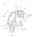
第2に、電線保持具(10)は、例えば図1及び図3〜8に示すように、次の構成からなる。
(1)保持具本体(60)
保持具本体(60)は、例えば図1に示すように、被取付物(例えば金属ステー50)に固定する固定手段(例えばアンカー部100)、及び固定手段(例えばアンカー部100)の下側に位置し、電線類(例えば送電用ケーブル30)を仮置き可能な抱持部(80)を備えるものである。First, as shown in FIGS. 2 and 18, for example, an electric wire holder (10) for fixing electric wires (for example, a power transmission cable 30) to an attached object (for example, a metal stay 50).
Secondly, the electric wire holder (10) has the following configuration as shown in FIGS. 1 and 3 to 8, for example.
(1) Holder body (60)
As shown in FIG. 1, for example, the holder main body (60) is fixed to an attachment object (for example, a metal stay 50), and is fixed to a lower part of the fixing means (for example, the anchor part 100). It is provided with a holding portion (80) that is positioned and can temporarily place electric wires (for example, the power transmission cable 30).
(2)可動アーム(70)
可動アーム(70)は、例えば図1及び図18に示すように、保持具本体(60)に可動可能に支持され、抱持部(80)に仮置きされた電線類(例えば送電用ケーブル30)を抱持部(80)との間で抱持するものである。
第3に、可動アーム(70)と抱持部(80)との間には、例えば図18及び図20に示すように、電線類(例えば送電用ケーブル30)を抱持部(80)に抱持させた抱持状態に可動アーム(70)をロックするためのロック手段(例えばラチェット81とロック爪124とのかみ合い)を備える。(2) Movable arm (70)
As shown in FIGS. 1 and 18, for example, the movable arm (70) is movably supported by the holder body (60) and temporarily placed on the holding portion (80) (for example, a
Third, between the movable arm (70) and the holding portion (80), as shown in FIGS. 18 and 20, for example, wires (for example, a power transmission cable 30) are connected to the holding portion (80). Locking means (for example, engagement between the
第4に、保持具本体(60)と可動アーム(70)との間には、例えば図1に示すように、非抱持状態を維持する静止手段(例えば支持アーム91とくびれ部112との摩擦抵抗)を備える。
第5に、保持具本体(60)と可動アーム(70)との間には、例えば図1、図3及び図4に示すように、可動アームを回転可能に支持する軸部(111)と軸穴(92)とのいずれか一方をそれぞれに設けている。
第6に、抱持部(80)は、例えば図1、図3及び図4に示すように、保持具本体(60)の一端部から下向きに、C字形の円弧状に屈曲して延び、自由端部が、電線類(例えばケーブル30)を差し込み可能な隙間を保って、前記保持具本体(60)の他端部から下方に離れて位置する。
(請求項2)
請求項2に記載の発明は、上記した請求項1に記載の発明の特徴点に加え、次の点を特徴とする。Fourth, between the holder main body (60) and the movable arm (70), as shown in FIG. 1, for example, stationary means (for example, a
Fifthly, between the holder main body (60) and the movable arm (70), as shown in FIGS. 1, 3 and 4, for example, there is a shaft portion (111) for rotatably supporting the movable arm. Either one of the shaft holes (92) is provided.
Sixth, the holding part (80) extends downwardly from one end part of the holder body (60), for example, as shown in FIGS. The free end portion is positioned away from the other end portion of the holder body (60) while maintaining a gap into which electric wires (for example, the cable 30) can be inserted.
(Claim 2)
The invention described in claim 2 is characterized by the following points in addition to the characteristics of the invention described in claim 1 described above.
第1に、被取付物(例えば金属ステー50)には、例えば図1に示すように、固定手段(例えばアンカー部100)を固定するための取付穴(54)を設ける。
第2に、固定手段(例えばアンカー部100)は、例えば図22に示すように、取付穴(54)の形状変化に対応するアタッチメント(200,210)を取り付けることができるようにしている。
(請求項3)
請求項3に記載の発明は、上記した請求項1又は請求項2に記載の発明の特徴点に加え、次の点を特徴とする。First, the attachment object (for example, the metal stay 50) is provided with an attachment hole (54) for fixing the fixing means (for example, the anchor portion 100) as shown in FIG.
Second, the fixing means (for example, the anchor portion 100) can attach attachments (200, 210) corresponding to changes in the shape of the mounting hole (54) as shown in FIG. 22, for example.
(Claim 3)
The invention described in claim 3 is characterized by the following points in addition to the features of the invention described in claim 1 or claim 2 described above.
第1に、保持具本体(60)と可動アーム(70)との間には、例えば図1、図3、図4及び図18に示すように、可動アーム(70)を回転可能に支持する軸部(111)と軸穴(102)とのいずれか一方をそれぞれに設けている。
第2に、軸部(111)と軸穴(102)とは、例えば図18に示すように、抱持状態において互いに密着するようにしている。
(請求項4)
請求項4に記載の発明は、次の点を特徴とする。First, the movable arm (70) is rotatably supported between the holder body (60) and the movable arm (70), as shown in FIGS. 1, 3, 4, and 18, for example. Either the shaft portion (111) or the shaft hole (102) is provided in each.
Second, the shaft portion (111) and the shaft hole (102) are in close contact with each other in the holding state, as shown in FIG. 18, for example.
(Claim 4)
The invention described in claim 4 is characterized by the following points.
第1に、例えば図2及び図18に示すように、構造物(例えば屋根材40)の上に間隔を保って取り付けられる固定物(例えばソーラーパネル20)との間に配線される電線類(例えば送電用ケーブル30)を、被取付物(例えば金属ステー50)に固定する電線保持具(10)である。
第2に、電線保持具(10)は、例えば図1及び図3〜8に示すように、次の構成を備える。First, for example, as shown in FIGS. 2 and 18, electric wires that are wired between a fixed object (for example, a solar panel 20) that is mounted on a structure (for example, a roofing material 40) at an interval. For example, it is an electric wire holder (10) for fixing the power transmission cable 30) to an attachment object (for example, a metal stay 50).
Secondly, the electric wire holder (10) has the following configuration as shown in FIG. 1 and FIGS.
(1)保持具本体(60)
保持具本体(60)は、例えば図1に示すように、固定物(例えばソーラーパネル20)に固定する固定手段(例えばアンカー部100)、及び固定手段(例えばアンカー部100)の下側に位置し、電線類(例えば送電用ケーブル30)を仮置き可能な抱持部(80)を備えるものである。(1) Holder body (60)
As shown in FIG. 1, for example, the holder main body (60) is fixed to a fixed object (for example, the solar panel 20), and is positioned below the fixing means (for example, the anchor part 100). In addition, a holding portion (80) capable of temporarily placing electric wires (for example, the power transmission cable 30) is provided.
(2)可動アーム(70)
可動アーム(70)は、例えば図1及び図18に示すように、保持具本体(60)に回動可能に支持され、抱持部(80)に仮置きされた電線類(例えば送電用ケーブル30)を抱持部(80)との間で抱持するものである。
第3に、可動アーム(70)と抱持部(80)との間には、例えば図18及び図20に示すように、電線類(例えば送電用ケーブル30)を抱持部(80)に抱持させた抱持状態に可動アーム(70)をロックするためのロック手段(例えばラチェット81とロック爪124とのかみ合い)を備える。(2) Movable arm (70)
As shown in FIGS. 1 and 18, for example, the movable arm (70) is rotatably supported by the holder body (60) and temporarily placed on the holding portion (80) (for example, a power transmission cable). 30) is held between the holding unit (80).
Third, between the movable arm (70) and the holding portion (80), as shown in FIGS. 18 and 20, for example, wires (for example, a power transmission cable 30) are connected to the holding portion (80). Locking means (for example, engagement between the
第4に、可動アーム(70)は、例えば図18に示すように、構造物(例えば屋根材40)に最接近した状態において、当該構造物(例えば屋根材40)との間に隙間を保って回動するようにしている。Fourth, as shown in FIG. 18, for example, the movable arm (70) maintains a gap between the movable arm (70) and the structure (for example, the roofing material 40) in the state closest to the structure (for example, the roofing material 40). To rotate.
第5に、構造物は、例えば図2に示すように、屋根材(40)である。、
第6に、固定物は、例えば図2に示すように、ソーラーパネル(20)や当該ソーラーパネル(20)を取り付ける架台(例えば金属ステー50)である。
第7に、ロック手段は、次の構成から構成されている。
(3)ラチェット(81)
ラチェット(81)は、抱持部(80)の下側に位置する外周に沿って形成されたものである。
(4)ロック爪(124)
ロック爪(124)は、例えば図15に示すように、解除アーム(122)の端部からラチェット(81)に向かって屈曲し、ラチェット(81)の一つの歯にはまり込むものである。Fifth, the structure is a roofing material (40) as shown in FIG. 2, for example. ,
Sixth, the fixed object is, for example, as shown in FIG. 2, a solar panel (20) or a mount (for example, a metal stay 50) to which the solar panel (20) is attached.
Seventh, thelocking means is configured as follows.
(3) Ratchet (81)
The ratchet (81) is formed along the outer periphery located below the holding part (80).
(4) Lock claw (124)
For example, as shown in FIG. 15, the lock claw (124) is bent from the end of the release arm (122) toward the ratchet (81) and fits into one tooth of the ratchet (81).
本発明は、以上のように構成されているので、以下に記載されるような効果を奏する。(請求項1)
請求項1に記載の発明によれば、次のような効果を奏する。
すなわち、請求項1に記載の発明によれば、保持具本体の抱持部に電線類を仮置きしながら配線でき、配線後、非抱持状態に静止している可動アームを抱持部に向かって可動させることで、当該抱持部に電線類を抱持した抱持状態にロックすることができる。
(請求項2)
請求項2に記載の発明によれば、上記した請求項1に記載の発明の効果に加え、次のような効果を奏する。Since this invention is comprised as mentioned above, there exists an effect as described below. (Claim 1)
According to invention of Claim 1, there exist the following effects.
That is, according to the first aspect of the present invention, it is possible to wire while temporarily placing electric wires on the holding portion of the holder body, and after the wiring, the movable arm that is stationary in a non-holding state is used as the holding portion. By making it move toward, it can be locked in the holding state in which the electric wires are held in the holding portion.
(Claim 2)
According to the invention described in claim 2, in addition to the effect of the invention described in claim 1, the following effect is obtained.
すなわち、請求項2に記載の発明によれば、固定手段にアタッチメントを取り付けることで、異なる形状の種々の取付穴に固定することができる。
(請求項3)
請求項3に記載の発明によれば、上記した請求項1又は請求項2に記載の発明の効果に加え、次のような効果を奏する。That is, according to the invention described in claim 2, by attaching the attachment to the fixing means, it can be fixed to various mounting holes of different shapes.
(Claim 3)
According to the invention described in claim 3, in addition to the effect of the invention described in claim 1 or 2, the following effect is obtained.
すなわち、請求項3に記載の発明によれば、電線類の抱持状態において、保持具本体と可動アームとの間の軸部と軸穴とを密着させることで、保持具本体と可動アームとの間のがた付きを防止することができる。
(請求項4)
請求項4に記載の発明によれば、次のような効果を奏する。That is, according to the invention described in claim 3, in the state of holding the electric wires, the shaft body and the shaft hole between the holder body and the movable arm are brought into close contact with each other. It is possible to prevent rattling between the two.
(Claim 4)
According to invention of Claim 4, there exist the following effects.
すなわち、請求項4に記載の発明によれば、構造物と、その上に間隔を保って取り付けられた固定物との間に、電線類を仮置きしながら配線でき、配線後、構造物と固定物との間隔内で可動アームを回動させることで、構造物と固定物との間隔内に電線保持具を介して電線類を固定することができる。That is, according to the invention described in claim 4, wiring can be wired while temporarily placing electric wires between the structure and a fixed object attached on the structure, and after the wiring, By rotating the movable arm within the distance from the fixed object, the electric wirescan be fixed via the electric wire holder within the distance between the structure and the fixed object.
これに加え、請求項4に記載の発明によれば、屋根材に固定するソーラーパネルの配線に好適な電線保持具を提供することができる。In addition, according to the invention described in claim 4, it is possible to provide an electric wire holder suitable for wiring of a solar panel fixedto a roof material.
(電線保持具10)
図1中、10は、電線保持具10に関し、図2に示すように、例えばソーラーパネル20(固定物の一例)の送電用ケーブル30(電線類、以下「ケーブル30」ともいう。)の配線に使用される。
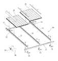
ソーラーパネル20は、図2に示すように、瓦等の屋根材40(構造物)に金属ステー50(被取付物)を介して固定される。(Wire holder 10)
In FIG. 1,
As shown in FIG. 2, the solar panel 20 is fixed to a roof material 40 (structure) such as a tile via a metal stay 50 (attachment).
金属ステー50は、図2に示すように、屋根材40に支持金具53を介して複数本の縦桟51を渡らせ、更に縦桟51に横桟52を渡らせて固定する。
横桟52には、図2に示すように、ソーラーパネル20を固定する。送電用ケーブル30は、図示しないが、横桟52に沿って配線され、図18に示すように、電線保持具10を介して横桟52に対して固定される。As shown in FIG. 2, the
As shown in FIG. 2, the solar panel 20 is fixed to the
横桟52は、図2に示すように、縦桟51を介して屋根材40に固定され、屋根材40の上に間隔を持って取り付けられる。横桟52には、図1に示すように、電線保持具10を取り付けるための取付穴54を設けている。取付穴54は、横桟52を上下に貫通し、例えば円形に形成されている。
なお、取付穴54を、円形に形成したが、これに限定されず、方形等の非円形に形成しても良い。As shown in FIG. 2, the
The mounting
また、固定物として、ソーラーパネル20を例示したが、これに限定されず、当該ソーラーパネル20を取り付ける架台、例えば金属ステー50でも良い。さらに、電線類として送電用ケーブル30を例示し、構造物として屋根材40を例示し、被取付物として金属ステー50を例示したが、これらに限定されない。また、さらに、ソーラーパネル20を取り付ける架台として、金属ステー50を例示したが、これに限定されないし、又、金属ステー50として、縦桟51、横桟52、支持金具53を例示したが、これらにも限定されない。
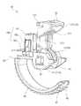
電線保持具10は、図3及び図4に示すように、大別すると、次の各部を備える。Further, although the solar panel 20 is illustrated as a fixed object, the present invention is not limited to this, and a mount for mounting the solar panel 20, for example, a
As shown in FIGS. 3 and 4, the
なお、次の(1)及び(2)については、後述する。
(1)保持具本体60
(2)可動アーム70
なお、電線保持具10の各部は、上記した(1)及び(2)に限定されない。
(保持具本体60)
保持具本体60は、図1に示すように、金属ステー50(被取付物)の横桟52に固定されるとともに、ケーブル30(電線類)を仮置き可能なものである。The following (1) and (2) will be described later.
(1)
(2)
In addition, each part of the
(Holder body 60)
As shown in FIG. 1, the holder
保持具本体60は、後述する可動アーム70と一体的に適度な弾性と剛性とを有する、「PBT」(ポリブチレンテレフタレート)等の熱可塑性樹脂で一体的に成型されている。なお、「PBT」は、耐熱性,耐薬品性,電気特性,寸法安定性,成形性に優れ,難燃性も持たせやすいという特徴がある。また、保持具本体60を、可動アーム70と一体的に成形したが、これに限定されず、両者を別々に成形し、組み立てても良い。 The holder
保持具本体60は、大別すると、図2〜15に示すように、次の各部を備える。
なお、次の(1)〜(3)については、後述する。
(1)抱持部80
(2)アーム支持部90
(3)アンカー部100(固定手段)
なお、保持具本体60の各部は、上記した(1)〜(3)に限定されない。
(可動アーム70)
可動アーム70は、図1、図3〜6及び図18に示すように、保持具本体60に可動可能に支持され、後述する抱持部80に仮置きされたケーブル30(電線類)を抱持部80との間で抱持するものである。The
The following (1) to (3) will be described later.
(1) Holding
(2)
(3) Anchor part 100 (fixing means)
In addition, each part of the holder
(Movable arm 70)
As shown in FIGS. 1, 3 to 6, and 18, the
また、可動アーム70は、屋根材40(構造物)に最接近した状態において、当該屋根材40との間に隙間を保って回動するようにしている。
可動アーム70は、大別すると、図3及び図4に示すように、次の各部を備える。
なお、次の(1)及び(2)については、後述する。
(1)可動部110
(2)ロック部120
なお、可動アーム70の各部は、上記した(1)及び(2)に限定されない。
(抱持部80)
抱持部80は、図1及び図3〜4に示すように、後述するアンカー部100(固定手段)の下側に位置し、ケーブル30(電線類)を仮置き可能なものである。In addition, the
The
The following (1) and (2) will be described later.
(1)
(2)
In addition, each part of the
(Holding part 80)
As shown in FIGS. 1 and 3 to 4, the holding
抱持部80は、保持具本体60の一端部から下向きに、C字形の円弧状に屈曲して延び、自由端部が、ケーブル30(電線類)を差し込み可能な隙間を保って、保持具本体60の他端部から下方に離れて位置する。
なお、抱持部80を、C字形の円弧状にに屈曲させたが、これに限定されず、J字形に屈曲させたり、或いは円弧でなく、矩形や角形に屈曲させても良い。The holding
In addition, although the holding
抱持部80は、図1及び図3〜6、図8、図9及び図13に示すように、次の各部を備える。
なお、抱持部80の各部は、次の(1)及び(2)に限定されない。
(1)ラチェット81
ラチェット81は、図1及び図3〜6、図8、図9及び図13に示すように、抱持部80の下側に位置する外周に沿って形成され、傾斜部を自由端部側に向け、傾斜部と背向する直立部を基端部側に向けて位置させている。As shown in FIGS. 1 and 3 to 6, 8, 9, and 13, the holding
In addition, each part of the holding
(1)
The
(2)ガイドリブ82
ガイドリブ82は、図1及び図3〜6、図8、図9、図13、図20及び図21に示すように、外周に沿って突出し、抱持部80の幅方向の中央に位置し、ラチェット81を幅方向に二分する。ガイドリブ82は、先端部に向かって細くなった断面台形形に形成され、両側面がテーパー面となっている。(2)
The
ガイドリブ82の両側面のテーパー面には、図20及び図21に示すように、後述するロック部120の解除アーム122が当接する。
(アーム支持部90)
アーム支持部90は、図3及び図4に示すように、抱持部80を有する保持具本体60の一端部と、後述するアンカー部100をはさんで反対側に位置する他端部に位置し、可動アーム70の後述する可動部110を可動可能に支持するためのものである。As shown in FIGS. 20 and 21, release
(Arm support 90)
As shown in FIGS. 3 and 4, the
アーム支持部90は、図3及び図4に示すように、大別すると、次の各部を備える。
なお、アーム支持部90の各部は、次の(1)及び(2)に限定されない。
(1)支持アーム91
支持アーム91は、図3及び図4に示すように、保持具本体60の他端部から延び、保持具本体60の幅方向に離れて一対形成されている。支持アーム91の間隔内には、可動アーム70の後述する可動部110がはまり込む。As shown in FIG. 3 and FIG. 4, the
In addition, each part of the
(1)
As shown in FIGS. 3 and 4, the
(2)軸穴92
軸穴92は、図3及び図4に示すように、一対の支持アーム91の自由端部にそれぞれ形成され、又、一対の軸穴92は相対向して形成されている。軸穴92は、支持アーム91の厚み方向に貫通し、正方形方に形成されている。一対の軸穴92には、後述する可動部110の一対の軸部111がそれぞれはまり込む。(2)
As shown in FIGS. 3 and 4, the shaft holes 92 are respectively formed at the free ends of the pair of
なお、軸穴92を、正方形に形成したが、これに限定されず、正方形以外の正多角形のほか、円形に形成しても良い。また、支持アーム91に、軸穴92を形成し、可動アーム70に軸部111を形成したが、これに限定されず、逆に支持アーム91に軸部を形成し、可動アーム70に軸穴を形成しても良い。
(アンカー部100(固定手段))
アンカー部100は、図3、図4及び図10〜12に示すように、金属ステー50(被取付物)に固定するためのものであり、固定手段として機能する。The
(Anchor part 100 (fixing means))
As shown in FIGS. 3, 4, and 10 to 12, the
なお、固定手段として、ボックスアンカー形のアンカー部100を例示したが、これに限定されず、いわゆるカヌー形としても良い。
アンカー部100は、図3、図4及び図10〜12に示すように、大別すると、次の各部を備える。
なお、アンカー部100の各部は、次の(1)〜(3)に限定されない。In addition, although the box anchor
As shown in FIGS. 3, 4, and 10 to 12, the
In addition, each part of the
(1)ボックス部101
ボックス部101は、図3、図4及び図10〜12に示すように、保持具本体60の長さ中央の上面から上方に向かって延び、円筒形に形成されている。ボックス部101の外径は、横桟52の円形の取付穴54の内径以下に設定されている。
なお、ボックス部101を、円筒形に形成したが、これに限定されず、角筒形に形成しても良い。(1)
As shown in FIGS. 3, 4, and 10 to 12, the
In addition, although the
(2)アンカー爪102
アンカー爪102は、図3、図4及び図10〜12に示すように、ボックス部101の外周から弾性的に複数個突出する。アンカー爪102は、ボックス部101の直径方向に一対設けられ、斜面を上方に向け、斜面に隣接し、ボックス部101と平行で、横桟52に当接する当接面を下側に向けた略直角三角形形に形成されている。(2)
As shown in FIGS. 3, 4, and 10 to 12, a plurality of
アンカー爪102の当接面からボックス部101の上面での距離は、横桟52の板厚に略等しく設定されている。
なお、アンカー爪102を、ボックス部101の直径方向に一対設けたが、これに限定されず、放射状に3個以上設けても良い。
(3)解除レバー103
解除レバー103は、図3、図4及び図10〜12に示すように、アンカー爪102のロック状態を解除するためのものである。アンカー爪102の下端部から断面L字形に屈曲して延びる。
(可動部110)
可動部110は、図3及び図4に示すように、アーム支持部90の一端部、例えば上端部に位置し、アーム支持部90に可動可能に支持されている。The distance from the contact surface of the
Although a pair of
(3)
The
(Moving part 110)
As shown in FIGS. 3 and 4, the
可動部110は、図3及び図4に示すように、次の各部を備える。
なお、可動部110の各部は、次の(1)及び(2)に限定されない。
(1)軸部111
軸部111は、図3及び図4に示すように、可動部110の幅方向の両端部から一対突出し、支持アーム91の軸穴92に回動可能にはまり込むものである。As shown in FIGS. 3 and 4, the
In addition, each part of the
(1)
As shown in FIGS. 3 and 4, a pair of
軸部111は、角柱形に形成され、その外形を方形の軸穴92の内形より一回り小さく設定している。
(2)くびれ部112
くびれ部112は、図3、図4及び図16に示すように、軸部111に隣接して形成され、可動アーム70の幅を減少させることでくびれさせている。くびれ部112の幅は、支持アーム91の対向間隔以上に設定され、本実施の形態では支持アーム91の対向間隔に等しく設定されている。The
(2)
As shown in FIGS. 3, 4, and 16, the
支持アーム91を上方に回動させた状態において、図1及び図17に示すように、保持具本体60の下面と抱持部80の自由端部との間に、ケーブル30(電線類)を挿入可能な隙間が形成される。このとき、くびれ部112は、支持アーム91の対向間隔内にはまり込み、両者の摩擦抵抗により、支持アーム91を上方に回動した位置に静止し、両者は静止手段として機能する。 In the state where the
静止手段は、非抱持状態を維持するものである。なお、静止手段として、支持アーム91とくびれ部112を例示したが、これに限定されず、保持具本体60と可動アーム70との間に互いにはまり合う凹凸部の一方をそれぞれ設けても良い。
(ロック部120)
ロック部120は、図3、図4、図20及び図21に示すように、アーム支持部90の他端部、例えば下端部に位置し、ケーブル30(電線類)を抱持部80に抱持させた抱持状態に可動アーム70をロックするためのものである。A stationary means maintains a non-holding state. Although the
(Lock part 120)
As shown in FIGS. 3, 4, 20, and 21, the
ロック部120は、図3、図4、図20及び図21に示すように、大別すると、次の各部を備える。
なお、ロック部120の各部は、次の(1)〜(5)に限定されない。
(1)ガイド溝121
ガイド溝121は、図3、図4、図20及び図21に示すように、端面が開口した凹状に凹み、溝内に抱持部80がはまり込み、可動アーム70が軸部111を中心に回動することで、抱持部80の内周面に沿って移動する。As shown in FIGS. 3, 4, 20, and 21, the
In addition, each part of the lock |
(1)
As shown in FIGS. 3, 4, 20 and 21, the
(2)解除アーム122
解除アーム122は、図3、図4、図20及び図21に示すように、ガイド溝121の開放側端面から、抱持部80の外周面に形成されたラチェット81に臨む。解除アーム122は、全体が略L字形に屈曲し、可動アーム70の幅方向に一対形成されている。解除アーム122は、ガイドリブ82の両側面のテーパー面に当接し、手で操作した際に、互いに接近しながらラチェット81から離れる方向に上昇し、このとき、後述するロック爪124をラチェット81から係脱させる。(2)
As shown in FIGS. 3, 4, 20, and 21, the
(3)連結部123
連結部123は、図3、図4、図20及び図21に示すように、アーム支持部90の他端部と解除アーム122とを弾性的に連結するものである。解除アーム122は、連結部123の弾性復元力により、ラチェット81に接近する方向に付勢される。
(4)ロック爪124
ロック爪124は、図3、図4、図20及び図21に示すように、解除アーム122の端部からラチェット81に向かって略L字形に屈曲し、ラチェット81の一つの歯にはまり込むものである。(3) Connecting
As shown in FIGS. 3, 4, 20, and 21, the connecting
(4)
As shown in FIGS. 3, 4, 20, and 21, the
(5)当接部125
当接部125は、図3、図4、図18及び図19に示すように、抱持部80に仮置きされたケーブル30(電線類)に当接するものであり、ケーブル30と対向する内側面がケーブル30の外周に沿って略V字形或いは略L字形に屈曲している。
(電線保持具10の使用方法)
つぎに、上記した構成を有する電線保持具10の使用方法について説明する。(5)
As shown in FIGS. 3, 4, 18, and 19, the abutting
(How to use the wire holder 10)
Next, a method for using the
まず、電線保持具10を、図17に示すように、屋根材40(構造物)と横桟52との間隔内に位置させ、横桟52の取付穴54に合わせて、アンカー部100を下側から挿入して固定する。こうして、横桟52に対して固定することで、電線保持具10は、屋根材40(構造物)と横桟52との間隔内に配置される。
このとき、電線保持具10の抱持部80の外周が、図17に示すように、屋根材40(構造物)の上面から上方に離れて位置する。First, as shown in FIG. 17, the
At this time, as shown in FIG. 17, the outer periphery of the holding
つぎに、電線保持具10の抱持部80に、図1に示すように、ケーブル30(電線類)を仮置きして配線する。
配線後、可動アーム70を、図18に示すように、軸部111を中心に旋回させる。
可動アーム70を下方に旋回させると、図20に示すように、ガイド溝121に抱持部80がはまり、ロック爪124がラチェット81の歯にはまり込む。Next, as shown in FIG. 1, a cable 30 (electric wires) is temporarily placed on the holding
After wiring, the
When the
この状態で、抱持部80の自由端部と、保持具本体60の下面との間の開放面が、図18に示すように、可動アーム70により塞がれる。
つぎに、可動アーム70を更に旋回させると、図18に示すように、その当接部125によりケーブル30を抱持部80の奥に向かって押し付ける。
このとき、ロック爪124が、ラチェット81の歯の正面により押し上げられ、歯を乗り越えるようにして抱持部80の奥に向かって進む。In this state, the open surface between the free end portion of the holding
Next, when the
At this time, the
また、可動アーム70は、屋根材40に最接近した状態において、当該屋根材40との間に隙間を保って回動するようにしている。
ケーブル30に押されて可動アーム70の旋回が不能となった位置で手を離すと、図20に示すように、ロック爪124とラチェット81の歯とのかみ合いにより、可動アーム70の戻り方向の旋回が阻止され、図18に示すように、抱持部80の内周面、可動アーム70の当接部125、並びに保持具本体60の下面の間で、ケーブル30が抱持される。In addition, the
When the hand is released at a position where the
また、このとき、ケーブル30の反力が、可動アーム70に作用し、角柱形の軸部111の角部が、図18に示すように、方形の軸穴92の辺に弾性的に当接し、両者のがた付きが防止される。
すなわち、図示しないが、ケーブル30の電線の外周に被覆されている絶縁ビニル等の絶縁体の弾性復元力により反力が作用する。Further, at this time, the reaction force of the
That is, although not shown, a reaction force acts by the elastic restoring force of an insulator such as insulating vinyl coated on the outer periphery of the
一方、ケーブル30の配線を変更する場合には、図21に示すように、手で一対の解除アーム122を互いに接近する方向に押し付ける。
解除アーム122を押すと、図21に示すように、ガイドリブ82の両側面のテーパー面に当接する。
解除アーム122を更に押すと、図21に示すように、互いに接近しながらラチェット81から離れる方向に浮上し、このとき、ロック爪124がラチェット81から係脱する。On the other hand, when changing the wiring of the
When the
When the
このため、解除アーム122を押しながら、可動アーム70を上方に旋回させることで、抱持部80の自由端部から可動アーム70を抜き取ることができる。
可動アーム70を抜くことで、図1に示すように、抱持部80の自由端部と、保持具本体60の下面との間の開放面が開放され、当該開放面からケーブル30を抜き取ったり、新たなケーブル30を差し込んみ、抱持部80に仮置きすることができる。Therefore, the
By pulling out the
上方に旋回した可動アーム70は、そのくびれ部112が、支持アーム91の対向間隔内にはまり込み、両者の摩擦抵抗により、支持アーム91を上方に回動した位置に静止する。
このため、配線の途中で、可動アーム70が下方に旋回し、抱持部80の自由端部と、保持具本体60の下面との間の開放面が塞がれるのを防止できる。
(第2の実施の形態)
つぎに、図22を用いて、本発明の第2の実施の形態について説明する。The
For this reason, it is possible to prevent the
(Second Embodiment)
Next, a second embodiment of the present invention will be described with reference to FIG.
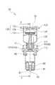
本実施の特徴は、アンカー部100(固定手段)に、図22に示すように、アタッチメント200を取り付けた点である。
アタッチメント200は、図22に示すように、内径がアンカー部100のボックス部101の外径にほぼ等しい、円筒形に形成されている。
アタッチメント200の外径は、ボックス部101の外径より一回り大きく形成されている。The feature of this embodiment is that an
As shown in FIG. 22, the
The outer diameter of the
アタッチメント200には、ボックス部101のアンカー爪102がそれぞれはまり込む、内外周に貫通する一対の開口部201を設けている。また、アタッチメント200には、開口部201と90度位相を異ならせ、アンカー爪202を設けている。
なお、本実施の形態の説明においては、先に図1〜21を用いて説明した第1の実施の形態と同一の構成部分については、同一符号を用いて説明を省略する。The
In the description of the present embodiment, the same components as those in the first embodiment described above with reference to FIGS.
本実施の形態によれば、アンカー部100にアタッチメント200を装着することで、図1に示す取付穴54より一回り大きい取付穴(図示せず)に、アンカー部100を取り付けることができる。
このため、外径の異なるアタッチメント200を用意することで、種々の穴径の取付穴(図示せず)に対応することができる。According to the present embodiment, by attaching
For this reason, by preparing the
また、アンカー爪202の当接面は、ボックス部101の上面から、横桟52の板厚に略等しい距離離れて位置する。
このため、高さの異なるアンカー爪202を形成したアタッチメント200を用意することで、横桟(図示せず)の板厚の変化にも柔軟に対応することができる。
さらに、アタッチメント200の材質を、電線保持具10と異なる材質、例えば軟質樹脂製とすることも可能である。
(第3の実施の形態)
つぎに、図23を用いて、本発明の第3の実施の形態について説明する。Further, the contact surface of the
For this reason, by preparing the
Furthermore, the
(Third embodiment)
Next, a third embodiment of the present invention will be described with reference to FIG.
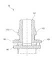
本実施の特徴は、アタッチメント210の外形を、図23に示すように、全体として箱形に形成した点である。
アタッチメント210は、図23に示すように、つば部211と、つば部211の上面から上方に突出する2個のブロック部212とから構成されている。
2個のブロック部212は、角筒形に形成され、アンカー部100のボックス部101がはまり込む隙間213を保って離れて位置する。つば部211には、図示しないが、アンカー部100の隙間213内に貫通する貫通孔を有し、当該貫通孔を通してボックス部101が2個のブロック部212の隙間213内に挿入されている。ボックス部101の対向する内側面には、図示しないが、ボックス部101のアンカー爪102がそれぞれはまり込む、内外に貫通する一対の開口部を設けている。The feature of this embodiment is that the outer shape of the
As shown in FIG. 23, the
The two
また、2個のブロック部212の外側面には、開口部と90度位相を異ならせ、アンカー爪214を設けている。
なお、本実施の形態の説明においては、先に図1〜21を用いて説明した第1の実施の形態と同一の構成部分については、同一符号を用いて説明を省略する。
本実施の形態によれば、アンカー部100にアタッチメント210を装着することで、図1に示す円形の取付穴54でなく、方形の取付穴(図示せず)に、アンカー部100を取り付けることができる。なお、箱形のアタッチメント210は、電線保持具10に付属され、図示しないが、主としてソーラーパネル20を取り付ける架台、例えば金属ステー50に固定する際に使用される。Also, anchor
In the description of the present embodiment, the same components as those in the first embodiment described above with reference to FIGS.
According to the present embodiment, by attaching the
(第1の実施の形態)
10 電線保持具 20 ソーラーパネル(固定物)
30 送電用ケーブル(電線類) 40 屋根材(構造物)
50 金属ステー(被取付物)
51 縦桟 52 横桟
53 支持金具 54 取付穴
60 保持具本体 70 可動アーム
80 抱持部
81 ラチェット(ロック手段の一部) 82 ガイドリブ
90 アーム支持部
91 支持アーム(静止手段の一部) 92 軸穴
100 アンカー部(固定手段)
101 ボックス部 102 アンカー爪
103 解除レバー
110 可動部
111 軸部 112 くびれ部(静止手段の一部)
120 ロック部
121 ガイド溝 122 解除アーム
123 連結部 124 ロック爪
125 当接部
(第2の実施の形態)
200 アタッチメント
201 開口部 202 アンカー爪(ロック手段の一部)
(第3の実施の形態)
210 アタッチメント
211 つば部 212 ブロック部
213 隙間 214 アンカー爪
(First embodiment)
10 Electric wire holder 20 Solar panel (fixed)
30 Transmission cables (electric wires) 40 Roofing materials (structures)
50 Metal stay (attachment)
51
53
60
80 Holding part
81 Ratchet (part of locking means) 82 Guide rib
90 Arm support
91 Support arm (part of stationary means) 92 Shaft hole
100 Anchor (fixing means)
101
103 Release lever
110 Moving parts
111
120 Lock part
121
123
125 Abutting part (second embodiment)
200 attachments
201
(Third embodiment)
210 Attachment
211
213
Claims (4)
Translated fromJapanese前記電線保持具は、
前記被取付物に固定する固定手段、及び
前記固定手段の下側に位置し、前記電線類を仮置き可能な抱持部を備える保持具本体と、
前記保持具本体に可動可能に支持され、前記抱持部に仮置きされた前記電線類を前記抱持部との間で抱持する可動アームとからなり、
前記可動アームと抱持部との間には、
前記電線類を前記抱持部に抱持させた抱持状態に前記可動アームをロックするためのロック手段を備え、
前記保持具本体と前記可動アームとの間には、
非抱持状態を維持する静止手段を備え、
前記保持具本体と前記可動アームとの間には、
前記可動アームを回転可能に支持する軸部と軸穴とのいずれか一方をそれぞれに設け、
前記抱持部は、
前記保持具本体の一端部から下向きに、C字形の円弧状に屈曲して延び、自由端部が、電線類を差し込み可能な隙間を保って、前記保持具本体の他端部から下方に離れて位置する、
ことを特徴とする電線保持具。An electric wire holder for fixing electric wires to an attachment,
The wire holder is
A fixing means for fixing to the attached object, and a holder body provided on the lower side of the fixing means, and having a holding part capable of temporarily placing the wires.
A movable arm that is movably supported by the holder body and holds the electric wires temporarily placed on the holding portion between the holding portion,
Between the movable arm and the holding part,
A lock means for locking the movable arm in a holding state in which the electric wires are held in the holding portion;
Between the holder body and the movable arm,
Comprising stationary means for maintaining an unembraced state,
Between the holder body and the movable arm,
Provide either one of a shaft portion and a shaft hole for rotatably supporting the movable arm,
The holding part is
Bending downward and extending from one end of the holder main body into a C-shaped arc shape, the free end is spaced downward from the other end of the holder main body while maintaining a gap into which wires can be inserted. Located
An electric wire holder characterized by that.
前記固定手段を固定するための取付穴を設け、
前記固定手段は、
前記取付穴の形状変化に対応するアタッチメントを取り付けることができるようにしていることを特徴とする請求項1に記載の電線保持具。In the attached object,
Provide a mounting hole for fixing the fixing means,
The fixing means includes
The electric wire holder according to claim 1, wherein an attachment corresponding to a change in shape of the attachment hole can be attached.
前記可動アームを回転可能に支持する軸部と軸穴とのいずれか一方をそれぞれに設け、
前記軸部と前記軸穴とは、
前記抱持状態において互いに密着するようにしていることを特徴とする請求項1又は請求項2に記載の電線保持具。Between the holder body and the movable arm,
Provide either one of a shaft portion and a shaft hole for rotatably supporting the movable arm,
The shaft portion and the shaft hole are:
The electric wire holder according to claim 1, wherein the electric wire holder is in close contact with each other in the holding state.
前記電線保持具は、
前記固定物に固定する固定手段、及び
前記固定手段の下側に位置し、前記電線類を仮置き可能な抱持部を備えた保持具本体と、
前記保持具本体に回動可能に支持され、前記抱持部に仮置きされた前記電線類を前記抱持部との間で抱持する可動アームとからなり、
前記可動アームと抱持部との間には、
前記電線類を前記抱持部に抱持させた抱持状態に前記可動アームをロックするためのロック手段を備え、
前記可動アームは、
前記構造物に最接近した状態において、当該構造物との間に隙間を保って回動するようにし、
前記構造物は、屋根材であり、
前記固定物は、ソーラーパネルや当該ソーラーパネルを取り付ける架台であり、
前記ロック手段は、
前記抱持部の下側に位置する外周に沿って形成されたラチェットと、
前記解除アームの端部から前記ラチェットに向かって屈曲し、前記ラチェットの一つの歯にはまり込むロック爪と、
から構成されている、
ことを特徴とする電線保持具。An electric wire holder for fixing electric wires wired between a fixed object and a fixed object attached to the structure on the attached object,
The wire holder is
A fixing means for fixing to the fixed object; and a holder main body provided with a holding portion which is located below the fixing means and capable of temporarily placing the electric wires;
A movable arm that is rotatably supported by the holder body and holds the electric wires temporarily placed on the holding portion with the holding portion,
Between the movable arm and the holding part,
A lock means for locking the movable arm in a holding state in which the electric wires are held in the holding portion;
The movable arm is
In a state closest to the structure, the structure isrotated with a gap between the structure and the structure.
The structure is a roofing material,
The fixed object is a mount for mounting the solar panel or the solar panel,
The locking means is
A ratchet formed along the outer periphery located below the holding portion;
A locking claw that bends from the end of the release arm toward the ratchet and fits into one tooth of the ratchet;
Composed of,
An electric wire holder characterized by that.
Priority Applications (5)
| Application Number | Priority Date | Filing Date | Title |
|---|---|---|---|
| JP2010222564AJP5762711B2 (en) | 2010-09-30 | 2010-09-30 | Electric wire holder |
| EP11828863.8AEP2623830A4 (en) | 2010-09-30 | 2011-09-20 | ELECTRIC WIRE BRACKET |
| US13/876,987US9267622B2 (en) | 2010-09-30 | 2011-09-20 | Electrical cable holder |
| CN201180047268.5ACN103140707B (en) | 2010-09-30 | 2011-09-20 | Electric wire holder |
| PCT/JP2011/071386WO2012043306A1 (en) | 2010-09-30 | 2011-09-20 | Electric wire holder |
Applications Claiming Priority (1)
| Application Number | Priority Date | Filing Date | Title |
|---|---|---|---|
| JP2010222564AJP5762711B2 (en) | 2010-09-30 | 2010-09-30 | Electric wire holder |
Publications (2)
| Publication Number | Publication Date |
|---|---|
| JP2012077824A JP2012077824A (en) | 2012-04-19 |
| JP5762711B2true JP5762711B2 (en) | 2015-08-12 |
Family
ID=45892768
Family Applications (1)
| Application Number | Title | Priority Date | Filing Date |
|---|---|---|---|
| JP2010222564AExpired - Fee RelatedJP5762711B2 (en) | 2010-09-30 | 2010-09-30 | Electric wire holder |
Country Status (5)
| Country | Link |
|---|---|
| US (1) | US9267622B2 (en) |
| EP (1) | EP2623830A4 (en) |
| JP (1) | JP5762711B2 (en) |
| CN (1) | CN103140707B (en) |
| WO (1) | WO2012043306A1 (en) |
Families Citing this family (18)
| Publication number | Priority date | Publication date | Assignee | Title |
|---|---|---|---|---|
| US9911880B2 (en)* | 2009-10-06 | 2018-03-06 | Solarcity Corporation | Method and apparatus for forming and mounting a photovoltaic array |
| JP5623869B2 (en)* | 2010-11-02 | 2014-11-12 | 株式会社ニフコ | Release operation piece for parts holder |
| US8770532B2 (en)* | 2011-05-13 | 2014-07-08 | Commscope, Inc. Of North Carolina | Cable retaining ring having slide closure and cable support tray including the cable retaining ring |
| KR101794861B1 (en)* | 2015-04-07 | 2017-11-07 | 안병준 | Device for fixing a part of cable system in a solar generating system |
| CN104832718B (en)* | 2015-04-14 | 2018-11-06 | 国网山东省电力公司菏泽供电公司 | A kind of cable tie |
| US20180093806A1 (en)* | 2016-10-05 | 2018-04-05 | Avery Dennison Corporation | Buddy clip |
| JP6800699B2 (en)* | 2016-10-25 | 2020-12-16 | 愛三工業株式会社 | Wiring holding structure |
| JP6702265B2 (en)* | 2017-05-30 | 2020-05-27 | 横河電機株式会社 | Wiring tie |
| EP3670938A1 (en)* | 2018-12-21 | 2020-06-24 | A. Raymond et Cie | Toolless slot fastener |
| CN111799741B (en)* | 2020-08-08 | 2025-03-28 | 河北黑牛电力金具有限公司 | A cable fixing hardware used in power construction |
| US11322867B1 (en) | 2020-12-07 | 2022-05-03 | Rockwell Automation Technologies, Inc. | Systems and methods for a cable connector |
| US12230931B2 (en) | 2020-12-07 | 2025-02-18 | Rockwell Automation Technologies, Inc. | Systems and methods for a cable connector |
| US11251550B1 (en) | 2020-12-07 | 2022-02-15 | Rockwell Automation Technologies, Inc. | Systems and methods for a cable connector |
| US11862889B2 (en) | 2021-02-09 | 2024-01-02 | Rockwell Automation Technologies, Inc. | Systems and methods for a cable connector |
| US11545801B2 (en) | 2021-02-15 | 2023-01-03 | Rockwell Automation Technologies, Inc. | Systems and methods for flat cable installation |
| JP7692328B2 (en)* | 2021-10-01 | 2025-06-13 | 未来工業株式会社 | Wiring/piping material holder |
| USD1067757S1 (en) | 2022-03-15 | 2025-03-25 | Panelclaw, Inc. | Wire clip and cover assembly |
| CN115313165A (en)* | 2022-08-22 | 2022-11-08 | 吉安市正和电力发展有限公司 | Low-voltage power distribution cabinet |
Family Cites Families (26)
| Publication number | Priority date | Publication date | Assignee | Title |
|---|---|---|---|---|
| US3523669A (en)* | 1968-11-08 | 1970-08-11 | Universal Oil Prod Co | Holding device for attachment to slotted track means |
| JPH0515672Y2 (en)* | 1988-05-06 | 1993-04-23 | ||
| DE3933304A1 (en) | 1989-10-05 | 1991-04-18 | United Carr Gmbh Trw | TAPE ELEMENT FOR WRAPPING AND HOLDING ITEMS |
| US5305978A (en)* | 1991-12-12 | 1994-04-26 | International Visual Corporation | Arcuate compression clamp |
| NO176370C (en) | 1992-08-25 | 1995-03-22 | Christensen As Ing Finn | Fixing device for attaching pipes to the substrate |
| JP2590484Y2 (en)* | 1993-01-29 | 1999-02-17 | 株式会社椿本チエイン | Locking structure between cable drag chain link plate and connecting rod |
| US5367750A (en)* | 1993-11-26 | 1994-11-29 | Ward; Mark C. | Wiring harness clip |
| JPH11153113A (en)* | 1997-11-21 | 1999-06-08 | Nifco Inc | Clip |
| US6206331B1 (en)* | 1998-07-30 | 2001-03-27 | Ewd, L.L.C. | D-shaped wire harness clip with ratchet lock |
| JP2001235065A (en)* | 1999-12-17 | 2001-08-31 | Kunimori Kagaku Co Ltd | Piping support |
| US6561471B1 (en)* | 2001-08-15 | 2003-05-13 | Hawie Robert L | Rod holder and bracket therefor |
| US7600349B2 (en)* | 2003-02-26 | 2009-10-13 | Unirac, Inc. | Low profile mounting system |
| JP2006067758A (en)* | 2004-08-30 | 2006-03-09 | Kawamura Electric Inc | Electric wire retainer |
| JP4336297B2 (en)* | 2004-12-06 | 2009-09-30 | 矢崎総業株式会社 | Clip, wire structure, and wire assembly method |
| US8015759B1 (en)* | 2005-08-16 | 2011-09-13 | Roofscreen Mfg. | Structural mounting for equipment on a rooftop |
| US8196360B2 (en)* | 2006-01-12 | 2012-06-12 | Msr Innovations Inc. | Photovoltaic solar roof tile assembly system |
| JP4996111B2 (en)* | 2006-02-28 | 2012-08-08 | 未来工業株式会社 | Wiring and piping material support |
| US7857269B2 (en)* | 2006-11-29 | 2010-12-28 | Pvt Solar, Inc. | Mounting assembly for arrays and other surface-mounted equipment |
| US7805814B2 (en)* | 2007-02-22 | 2010-10-05 | Marmon Utility Llc | Ratchet-head conductor locking medium voltage polymer insulator cable support hanger mount |
| JP4906553B2 (en)* | 2007-03-26 | 2012-03-28 | 因幡電機産業株式会社 | Long body support |
| US8132764B2 (en)* | 2009-02-09 | 2012-03-13 | Ray Kuipers | Quick-release adjustable mounting bracket |
| JP5394911B2 (en) | 2009-02-27 | 2014-01-22 | 住友化学株式会社 | Prepolymerization catalyst for olefin polymerization and process for producing olefin polymer |
| US8317526B2 (en)* | 2009-04-14 | 2012-11-27 | Halex Co. | Ground clamp |
| USD661177S1 (en)* | 2010-09-30 | 2012-06-05 | Yanegijutsukenkyujo Co., Ltd | Wire holder |
| US8408507B2 (en)* | 2010-10-06 | 2013-04-02 | Chi-Perng Liu | Locking device |
| US9109617B2 (en)* | 2012-12-12 | 2015-08-18 | Newfrey Llc | Self-closing positive engagement clip |
- 2010
- 2010-09-30JPJP2010222564Apatent/JP5762711B2/ennot_activeExpired - Fee Related
- 2011
- 2011-09-20WOPCT/JP2011/071386patent/WO2012043306A1/enactiveApplication Filing
- 2011-09-20CNCN201180047268.5Apatent/CN103140707B/ennot_activeExpired - Fee Related
- 2011-09-20EPEP11828863.8Apatent/EP2623830A4/ennot_activeWithdrawn
- 2011-09-20USUS13/876,987patent/US9267622B2/ennot_activeExpired - Fee Related
Also Published As
| Publication number | Publication date |
|---|---|
| US20130206929A1 (en) | 2013-08-15 |
| CN103140707A (en) | 2013-06-05 |
| CN103140707B (en) | 2015-11-25 |
| JP2012077824A (en) | 2012-04-19 |
| EP2623830A4 (en) | 2014-04-16 |
| US9267622B2 (en) | 2016-02-23 |
| EP2623830A1 (en) | 2013-08-07 |
| WO2012043306A1 (en) | 2012-04-05 |
Similar Documents
| Publication | Publication Date | Title |
|---|---|---|
| JP5762711B2 (en) | Electric wire holder | |
| EP2861386A1 (en) | Holding device with a stem part including a fin | |
| JP2008536748A (en) | Roof rack for vehicle and fixing method thereof | |
| JP5696278B2 (en) | Resin wiring clamp with metal clip | |
| JP2021057251A (en) | Wiring duct support component and wiring duct system | |
| KR20090068517A (en) | Slide assembly structure of cable tray | |
| JP3218772U (en) | Repellent line installation tool and repellent line installation tool set | |
| JP2017063573A (en) | Flat cable fixing structure | |
| JP4174796B2 (en) | Wiring / piping material receiving device and roller member for wiring / piping material receiving device | |
| JP2012057642A (en) | Wiring-piping material extraction device and wiring-piping material extractor | |
| JP2007173186A (en) | Breaker mounting structure | |
| JP5890632B2 (en) | Wiring duct and wiring duct installation method | |
| KR200428886Y1 (en) | Fixed clip structure for wire | |
| JP5185166B2 (en) | Pipe fitting | |
| JP2017153215A (en) | Fitting frame for wiring fixture | |
| JP2009027885A (en) | Wire harness protector and method of attaching the protector to the wire harness | |
| KR102484839B1 (en) | Double locking band cable | |
| JP3188054U (en) | Cable support | |
| JP7414309B2 (en) | Cable retainers and cable retention structures | |
| JP5024714B2 (en) | Nylon band for bundling and bundling method thereof | |
| KR101303132B1 (en) | Lighting apparatus | |
| JP2011249221A (en) | Attachment structure of connector | |
| JP6273579B2 (en) | Circuit breaker | |
| JP6258028B2 (en) | Wiring tool for ceiling penetration and its mounting structure | |
| KR101159732B1 (en) | End jig assembly of moving type |
Legal Events
| Date | Code | Title | Description |
|---|---|---|---|
| A621 | Written request for application examination | Free format text:JAPANESE INTERMEDIATE CODE: A621 Effective date:20130925 | |
| A131 | Notification of reasons for refusal | Free format text:JAPANESE INTERMEDIATE CODE: A131 Effective date:20140930 | |
| A521 | Request for written amendment filed | Free format text:JAPANESE INTERMEDIATE CODE: A523 Effective date:20141127 | |
| TRDD | Decision of grant or rejection written | ||
| A01 | Written decision to grant a patent or to grant a registration (utility model) | Free format text:JAPANESE INTERMEDIATE CODE: A01 Effective date:20150519 | |
| A61 | First payment of annual fees (during grant procedure) | Free format text:JAPANESE INTERMEDIATE CODE: A61 Effective date:20150610 | |
| R150 | Certificate of patent or registration of utility model | Ref document number:5762711 Country of ref document:JP Free format text:JAPANESE INTERMEDIATE CODE: R150 | |
| R250 | Receipt of annual fees | Free format text:JAPANESE INTERMEDIATE CODE: R250 | |
| R250 | Receipt of annual fees | Free format text:JAPANESE INTERMEDIATE CODE: R250 | |
| LAPS | Cancellation because of no payment of annual fees |