JP5759384B2 - Method and apparatus for feeding substances into a process reactor - Google Patents
Method and apparatus for feeding substances into a process reactorDownload PDFInfo
- Publication number
- JP5759384B2 JP5759384B2JP2011544788AJP2011544788AJP5759384B2JP 5759384 B2JP5759384 B2JP 5759384B2JP 2011544788 AJP2011544788 AJP 2011544788AJP 2011544788 AJP2011544788 AJP 2011544788AJP 5759384 B2JP5759384 B2JP 5759384B2
- Authority
- JP
- Japan
- Prior art keywords
- reactor
- biomass material
- pressure inside
- liquid
- container
- Prior art date
- Legal status (The legal status is an assumption and is not a legal conclusion. Google has not performed a legal analysis and makes no representation as to the accuracy of the status listed.)
- Expired - Fee Related
Links
- 238000000034methodMethods0.000titleclaimsdescription53
- 239000000126substanceSubstances0.000titleclaimsdescription10
- 230000008569processEffects0.000titledescription34
- 239000000463materialSubstances0.000claimsdescription139
- 239000007788liquidSubstances0.000claimsdescription63
- 239000002028BiomassSubstances0.000claimsdescription57
- 230000032258transportEffects0.000claimsdescription43
- XLYOFNOQVPJJNP-UHFFFAOYSA-NwaterSubstancesOXLYOFNOQVPJJNP-UHFFFAOYSA-N0.000claimsdescription41
- 238000004519manufacturing processMethods0.000claimsdescription14
- 238000001914filtrationMethods0.000claimsdescription9
- 230000006835compressionEffects0.000claimsdescription7
- 238000007906compressionMethods0.000claimsdescription7
- 238000012544monitoring processMethods0.000claimsdescription7
- 230000000750progressive effectEffects0.000claimsdescription7
- 238000006073displacement reactionMethods0.000claimsdescription6
- 239000002904solventSubstances0.000claimsdescription5
- 230000009056active transportEffects0.000claimsdescription3
- 239000013043chemical agentSubstances0.000claimsdescription3
- 238000007599dischargingMethods0.000claimsdescription3
- 238000012545processingMethods0.000claimsdescription3
- 238000010298pulverizing processMethods0.000claimsdescription3
- 238000004537pulpingMethods0.000claims1
- 230000018044dehydrationEffects0.000description15
- 238000006297dehydration reactionMethods0.000description15
- 238000007654immersionMethods0.000description14
- 238000005406washingMethods0.000description12
- LFQSCWFLJHTTHZ-UHFFFAOYSA-NEthanolChemical compoundCCOLFQSCWFLJHTTHZ-UHFFFAOYSA-N0.000description10
- 230000008901benefitEffects0.000description9
- 238000003825pressingMethods0.000description8
- 239000000835fiberSubstances0.000description7
- 238000011144upstream manufacturingMethods0.000description7
- 238000000227grindingMethods0.000description6
- 238000010586diagramMethods0.000description5
- 239000002023woodSubstances0.000description5
- QGZKDVFQNNGYKY-UHFFFAOYSA-NAmmoniaChemical compoundNQGZKDVFQNNGYKY-UHFFFAOYSA-N0.000description4
- 239000012620biological materialSubstances0.000description4
- 238000004140cleaningMethods0.000description4
- 239000007789gasSubstances0.000description4
- 230000005484gravityEffects0.000description4
- 239000000203mixtureSubstances0.000description4
- 239000002002slurrySubstances0.000description4
- 241000196324EmbryophytaSpecies0.000description3
- 238000009835boilingMethods0.000description3
- 230000006837decompressionEffects0.000description3
- 238000000855fermentationMethods0.000description3
- 230000004151fermentationEffects0.000description3
- 239000013505freshwaterSubstances0.000description3
- 150000004676glycansChemical class0.000description3
- 239000002029lignocellulosic biomassSubstances0.000description3
- 230000000670limiting effectEffects0.000description3
- 239000012528membraneSubstances0.000description3
- 239000002245particleSubstances0.000description3
- 229920001282polysaccharidePolymers0.000description3
- 239000005017polysaccharideSubstances0.000description3
- 239000002994raw materialSubstances0.000description3
- 239000007787solidSubstances0.000description3
- 238000011282treatmentMethods0.000description3
- MHAJPDPJQMAIIY-UHFFFAOYSA-NHydrogen peroxideChemical compoundOOMHAJPDPJQMAIIY-UHFFFAOYSA-N0.000description2
- 240000008042Zea maysSpecies0.000description2
- 235000005824Zea mays ssp. parviglumisNutrition0.000description2
- 235000002017Zea mays subsp maysNutrition0.000description2
- 229910021529ammoniaInorganic materials0.000description2
- 229920002678cellulosePolymers0.000description2
- 239000001913celluloseSubstances0.000description2
- 235000005822cornNutrition0.000description2
- 238000004821distillationMethods0.000description2
- 239000012530fluidSubstances0.000description2
- 238000011010flushing procedureMethods0.000description2
- 239000012634fragmentSubstances0.000description2
- 238000002309gasificationMethods0.000description2
- 230000007062hydrolysisEffects0.000description2
- 238000006460hydrolysis reactionMethods0.000description2
- 239000011344liquid materialSubstances0.000description2
- 230000009057passive transportEffects0.000description2
- 239000000047productSubstances0.000description2
- 230000004044responseEffects0.000description2
- 238000001223reverse osmosisMethods0.000description2
- 150000003839saltsChemical class0.000description2
- 238000007789sealingMethods0.000description2
- 238000002791soakingMethods0.000description2
- 239000011343solid materialSubstances0.000description2
- 239000010902strawSubstances0.000description2
- 235000000346sugarNutrition0.000description2
- 239000002699waste materialSubstances0.000description2
- NWUYHJFMYQTDRP-UHFFFAOYSA-N1,2-bis(ethenyl)benzene;1-ethenyl-2-ethylbenzene;styreneChemical compoundC=CC1=CC=CC=C1.CCC1=CC=CC=C1C=C.C=CC1=CC=CC=C1C=CNWUYHJFMYQTDRP-UHFFFAOYSA-N0.000description1
- BYHQTRFJOGIQAO-GOSISDBHSA-N3-(4-bromophenyl)-8-[(2R)-2-hydroxypropyl]-1-[(3-methoxyphenyl)methyl]-1,3,8-triazaspiro[4.5]decan-2-oneChemical compoundC[C@H](CN1CCC2(CC1)CN(C(=O)N2CC3=CC(=CC=C3)OC)C4=CC=C(C=C4)Br)OBYHQTRFJOGIQAO-GOSISDBHSA-N0.000description1
- 102000004190EnzymesHuman genes0.000description1
- 108090000790EnzymesProteins0.000description1
- 229920002488HemicellulosePolymers0.000description1
- BPQQTUXANYXVAA-UHFFFAOYSA-NOrthosilicateChemical compound[O-][Si]([O-])([O-])[O-]BPQQTUXANYXVAA-UHFFFAOYSA-N0.000description1
- 240000000111Saccharum officinarumSpecies0.000description1
- 235000007201Saccharum officinarumNutrition0.000description1
- 229920002472StarchPolymers0.000description1
- 229920002522Wood fibrePolymers0.000description1
- 238000013459approachMethods0.000description1
- 230000004888barrier functionEffects0.000description1
- 239000002551biofuelSubstances0.000description1
- 230000015572biosynthetic processEffects0.000description1
- 239000006227byproductSubstances0.000description1
- 235000013339cerealsNutrition0.000description1
- 230000008859changeEffects0.000description1
- 238000002485combustion reactionMethods0.000description1
- 230000000295complement effectEffects0.000description1
- 230000001276controlling effectEffects0.000description1
- 238000005260corrosionMethods0.000description1
- 230000007797corrosionEffects0.000description1
- 230000000593degrading effectEffects0.000description1
- 238000007865dilutingMethods0.000description1
- 238000009826distributionMethods0.000description1
- 238000011143downstream manufacturingMethods0.000description1
- 238000005553drillingMethods0.000description1
- 230000000694effectsEffects0.000description1
- 229920001971elastomerPolymers0.000description1
- 239000000806elastomerSubstances0.000description1
- 230000007071enzymatic hydrolysisEffects0.000description1
- 238000006047enzymatic hydrolysis reactionMethods0.000description1
- 239000002657fibrous materialSubstances0.000description1
- -1for exampleSubstances0.000description1
- 239000000446fuelSubstances0.000description1
- 239000008246gaseous mixtureSubstances0.000description1
- 238000003898horticultureMethods0.000description1
- 229910052500inorganic mineralInorganic materials0.000description1
- 239000003456ion exchange resinSubstances0.000description1
- 229920003303ion-exchange polymerPolymers0.000description1
- 238000012423maintenanceMethods0.000description1
- 229910021645metal ionInorganic materials0.000description1
- 239000007769metal materialSubstances0.000description1
- 239000011707mineralSubstances0.000description1
- 238000002156mixingMethods0.000description1
- 150000002772monosaccharidesChemical class0.000description1
- 230000036961partial effectEffects0.000description1
- 239000003208petroleumSubstances0.000description1
- 239000002861polymer materialSubstances0.000description1
- 238000007781pre-processingMethods0.000description1
- 238000005086pumpingMethods0.000description1
- 238000000746purificationMethods0.000description1
- 230000002829reductive effectEffects0.000description1
- 230000001105regulatory effectEffects0.000description1
- 230000000630rising effectEffects0.000description1
- 238000000926separation methodMethods0.000description1
- 239000004071sootSubstances0.000description1
- 235000019698starchNutrition0.000description1
- 239000008107starchSubstances0.000description1
- 230000003068static effectEffects0.000description1
- 150000008163sugarsChemical class0.000description1
- 239000000725suspensionSubstances0.000description1
- 230000001360synchronised effectEffects0.000description1
- 238000009997thermal pre-treatmentMethods0.000description1
- 238000012546transferMethods0.000description1
- 230000001960triggered effectEffects0.000description1
- 239000002025wood fiberSubstances0.000description1
Images


Classifications
- D—TEXTILES; PAPER
- D21—PAPER-MAKING; PRODUCTION OF CELLULOSE
- D21B—FIBROUS RAW MATERIALS OR THEIR MECHANICAL TREATMENT
- D21B1/00—Fibrous raw materials or their mechanical treatment
- D21B1/04—Fibrous raw materials or their mechanical treatment by dividing raw materials into small particles, e.g. fibres
- D21B1/12—Fibrous raw materials or their mechanical treatment by dividing raw materials into small particles, e.g. fibres by wet methods, by the use of steam
- C—CHEMISTRY; METALLURGY
- C08—ORGANIC MACROMOLECULAR COMPOUNDS; THEIR PREPARATION OR CHEMICAL WORKING-UP; COMPOSITIONS BASED THEREON
- C08H—DERIVATIVES OF NATURAL MACROMOLECULAR COMPOUNDS
- C08H8/00—Macromolecular compounds derived from lignocellulosic materials
- D—TEXTILES; PAPER
- D21—PAPER-MAKING; PRODUCTION OF CELLULOSE
- D21B—FIBROUS RAW MATERIALS OR THEIR MECHANICAL TREATMENT
- D21B1/00—Fibrous raw materials or their mechanical treatment
- D21B1/04—Fibrous raw materials or their mechanical treatment by dividing raw materials into small particles, e.g. fibres
- D21B1/12—Fibrous raw materials or their mechanical treatment by dividing raw materials into small particles, e.g. fibres by wet methods, by the use of steam
- D21B1/30—Defibrating by other means
- D21B1/34—Kneading or mixing; Pulpers
- D21B1/342—Mixing apparatus
- D—TEXTILES; PAPER
- D21—PAPER-MAKING; PRODUCTION OF CELLULOSE
- D21C—PRODUCTION OF CELLULOSE BY REMOVING NON-CELLULOSE SUBSTANCES FROM CELLULOSE-CONTAINING MATERIALS; REGENERATION OF PULPING LIQUORS; APPARATUS THEREFOR
- D21C7/00—Digesters
- D21C7/06—Feeding devices
- D—TEXTILES; PAPER
- D21—PAPER-MAKING; PRODUCTION OF CELLULOSE
- D21C—PRODUCTION OF CELLULOSE BY REMOVING NON-CELLULOSE SUBSTANCES FROM CELLULOSE-CONTAINING MATERIALS; REGENERATION OF PULPING LIQUORS; APPARATUS THEREFOR
- D21C11/00—Regeneration of pulp liquors or effluent waste waters
- D21C11/0007—Recovery of by-products, i.e. compounds other than those necessary for pulping, for multiple uses or not otherwise provided for
- D—TEXTILES; PAPER
- D21—PAPER-MAKING; PRODUCTION OF CELLULOSE
- D21C—PRODUCTION OF CELLULOSE BY REMOVING NON-CELLULOSE SUBSTANCES FROM CELLULOSE-CONTAINING MATERIALS; REGENERATION OF PULPING LIQUORS; APPARATUS THEREFOR
- D21C5/00—Other processes for obtaining cellulose, e.g. cooking cotton linters ; Processes characterised by the choice of cellulose-containing starting materials
- Y—GENERAL TAGGING OF NEW TECHNOLOGICAL DEVELOPMENTS; GENERAL TAGGING OF CROSS-SECTIONAL TECHNOLOGIES SPANNING OVER SEVERAL SECTIONS OF THE IPC; TECHNICAL SUBJECTS COVERED BY FORMER USPC CROSS-REFERENCE ART COLLECTIONS [XRACs] AND DIGESTS
- Y02—TECHNOLOGIES OR APPLICATIONS FOR MITIGATION OR ADAPTATION AGAINST CLIMATE CHANGE
- Y02E—REDUCTION OF GREENHOUSE GAS [GHG] EMISSIONS, RELATED TO ENERGY GENERATION, TRANSMISSION OR DISTRIBUTION
- Y02E50/00—Technologies for the production of fuel of non-fossil origin
- Y02E50/10—Biofuels, e.g. bio-diesel
Landscapes
- Engineering & Computer Science (AREA)
- Life Sciences & Earth Sciences (AREA)
- Chemical & Material Sciences (AREA)
- Wood Science & Technology (AREA)
- Mechanical Engineering (AREA)
- Chemical Kinetics & Catalysis (AREA)
- Materials Engineering (AREA)
- Health & Medical Sciences (AREA)
- Biochemistry (AREA)
- Medicinal Chemistry (AREA)
- Polymers & Plastics (AREA)
- Organic Chemistry (AREA)
- Processing Of Solid Wastes (AREA)
- Preparation Of Compounds By Using Micro-Organisms (AREA)
- Apparatus Associated With Microorganisms And Enzymes (AREA)
- Disintegrating Or Milling (AREA)
- Treatment Of Sludge (AREA)
Description
Translated fromJapanese本発明は、特に、脱水されたバイオマスが熱処理されその後発酵するためにプロセス反応器に導入される前に、バイオマスの含水量を制御するようにバイオマスを送り込み(in-feeding)かつ脱水するプロセスおよび装置に関する。本発明の説明はバイオマスに焦点を当てるが、本発明は、概して、液体物質と固体物質との混合物を含むスラリーまたはパルプの形態の材料に対し送込みおよび脱水プロセスを適用することにより、含水量を制御するように適用可能であることが考えられ、前記材料は、典型的には、液体において懸濁状態であり、浸漬液を有している。 The present invention particularly relates to a process for in-feeding and dehydrating biomass to control the moisture content of the biomass before the dehydrated biomass is heat treated and then introduced into the process reactor for fermentation. Relates to the device. While the description of the present invention focuses on biomass, the present invention generally relates to moisture content by applying a feed and dewatering process to a material in the form of a slurry or pulp containing a mixture of liquid and solid materials. The material is typically suspended in a liquid and has an immersion liquid.
プラントバイオマスから取り出される燃料の中で、エタノールは、石油由来製品に対する可能性がある代用品または補完するものとして特別の注目を集めてきた。バイオマスからのエタノールの製造は、通常、第1世代バイオエタノールとも呼ばれる穀物、サトウキビまたはトウモロコシ等、糖および澱粉が豊富な生物由来原料の発酵プロセスを通して得られる。 Among fuels extracted from plant biomass, ethanol has received particular attention as a possible substitute or complement to petroleum-derived products. Production of ethanol from biomass is usually obtained through a fermentation process of bio-derived raw materials rich in sugar and starch, such as cereals, sugarcane or corn, also called first generation bioethanol.
製造コストを最小限にするとともにバイオマスから製造されるバイオエタノールの可能性を増大させるために、園芸、農業、林業、材木業等からの低コストの副生成物、したがって、たとえば、藁、トウモロコシ茎、林業廃棄物、おが屑および木屑等の材料の形態でのリグノセルロース系バイオマスを使用することは極めて重要である。この種のバイオマスから製造されるエタノールは、第2世代バイオエタノールとも呼ばれる。 Low cost by-products from horticulture, agriculture, forestry, timber, etc., and thus, for example, straw, corn stalk, to minimize production costs and increase the potential of bioethanol produced from biomass It is very important to use lignocellulosic biomass in the form of materials such as forestry waste, sawdust and wood chips. Ethanol produced from this type of biomass is also called second generation bioethanol.
リグノセルロース系バイオマスは、ヘミセルロースおよびセルロースの形態の多糖類を含む。それらの糖をエタノールに発酵させる前に、多糖類を、その単糖類にまで分解しなければならない。多糖類を分解する一般的な方法は、酵素加水分解を用いるものである。酵素に対するバイオマスの可用性を増大させるために、リグノセルロース系バイオマスには、熱的/化学的前処理が行われることが多い。 Lignocellulosic biomass contains polysaccharides in the form of hemicellulose and cellulose. Before fermenting those sugars to ethanol, the polysaccharide must be broken down into its monosaccharides. A common method for degrading polysaccharides is to use enzymatic hydrolysis. In order to increase the availability of biomass for enzymes, lignocellulosic biomass is often subjected to thermal / chemical pretreatment.
熱化学的手法に続き、こうしたプロセスでは、多くの場合、生物学的物質の温度を、それが含まれている液体の沸点を上回る温度まで上昇させることが必要である。したがって、当業者は、流体を液体状態で維持しながら、温度を液体の沸点を上回る温度まで上昇させることができるように、生物学的物質を含むスラリーまたはパルプを加圧するという問題に直面することが多い。 Following thermochemical techniques, such processes often require raising the temperature of the biological material to a temperature above the boiling point of the liquid in which it is contained. Thus, those skilled in the art face the problem of pressurizing a slurry or pulp containing biological material so that the temperature can be raised to a temperature above the boiling point of the liquid while maintaining the fluid in a liquid state. There are many.
こうしたプロセスは、反応器チャンバ等の容器で行われることが多く、そこでは、多くの実際的な場合において、生物由来原料が大気条件で貯蔵器に保管されかつそこから取り出される間に、圧力および温度は大気条件に比較して上昇している。これは、安全性リスクおよびそれに関連する他の問題をあいまいにする(trick)傾向があり、それは、反応器内の上昇した圧力が、装置内で材料を上流に押し上げる傾向があり、場合によっては、非常に高温の蒸気、アンモニアまたは概して化学物質および他のガス状混合物のいわゆるバックフラッシュ(back flash)が、反応器から出てバイオエタノール製造システム内の上流に発生する可能性があることによる。こうしたバックフラッシュにより、たとえばシステムが故障し破壊することになる可能性があり、場合によっては、システムを操作している人間に対して危険をもたらす可能性がある。したがって、反応器内への生物由来材料の送込みを可能にする一方で、バックフラッシュの発生を防止することに関する問題がある。 Such processes are often performed in vessels such as reactor chambers, where, in many practical cases, pressure and pressure are maintained while biological materials are stored in and removed from the reservoir at atmospheric conditions. The temperature is rising compared to atmospheric conditions. This tends to trick the safety risk and other problems associated with it, as the increased pressure in the reactor tends to push the material upstream in the equipment, and in some cases This is due to the fact that so-called back flash of very hot steam, ammonia or generally chemicals and other gaseous mixtures can occur out of the reactor and upstream in the bioethanol production system. Such backflushing can, for example, cause the system to fail and be destroyed, and in some cases can pose a danger to the person operating the system. Thus, there is a problem with preventing the occurrence of backflush while allowing the delivery of biological material into the reactor.
さらなる態様では、効率的な製造システムでは、反応器内でのプロセスが連続的に行われることが必要である場合があり、こうした態様では、送込みが連続的でなければならないことに関するさらなる問題がある。 In a further aspect, an efficient manufacturing system may require the process in the reactor to be performed continuously, and in such an aspect, there is an additional problem with the feed must be continuous. is there.
この問題を解決することに関する提案がなされてきた。たとえば、特許文献1は、プラグスクリューフィーダを用いてパルプを反応器に向けて輸送することを提案している。スクリュー送りは、反応器のシールをもたらすように意図される「バイオプラグ(bio plug)」を製造する目的で、パルプが反応器の入口に向かう輸送中に脱水されかつ圧縮されるように構成される。この手法では、問題が是正されないことが判明しており、バイオマスの含水量、タイプ、粉砕、量、粒径および分布とプラグを得るための送込み速度との組合せにおいて必要に迫られて貪欲な(needy greedy)制御が必要となる。当然ながら、原料の構成は広い範囲で変化し、最終結果は、製造されたプラグが常に高度なシールをもたらすとは限らないため、安全問題は解決されず、プロセスはそれほど有効ではない、ということになる。 Proposals have been made to solve this problem. For example, Patent Document 1 proposes transporting pulp toward a reactor using a plug screw feeder. Screw feed is configured so that the pulp is dewatered and compressed during transport towards the reactor inlet for the purpose of producing a `` bio plug '' intended to provide a reactor seal. The This approach has been found to not correct the problem and is greedy as needed in the combination of biomass moisture content, type, grinding, amount, particle size and distribution with feed rate to obtain plugs. (needy greedy) control is required. Of course, the composition of the raw materials varies widely, and the end result is that the manufactured plug does not always provide a high degree of sealing, so the safety problem is not solved and the process is not very effective. become.
バイオプラグ法の可用性を向上させるために、異なる液圧方法が適用されている。たとえば、特許文献2では、こうした液圧方法は、バイオプラグのさらなる圧縮を提供するスクリューフィーダの往復運動を含むか、またはスクリューフィーダの端部に反応器への入口を閉鎖することができる弁を含む。 Different hydraulic methods have been applied to improve the availability of the bioplug method. For example, in U.S. Patent No. 6,057,033, such a hydraulic method includes a reciprocating motion of a screw feeder that provides further compression of the bioplug, or a valve that can close the inlet to the reactor at the end of the screw feeder. Including.
特許文献3は、タンピングスクリュー(tamping screw)を通るように木屑を送ることにより、木屑から木材繊維を作成する装置であって、スクリューから出る木屑のプラグの導電性を測定することと、その結果を、木屑および/または繊維の下流処理を制御する制御パラメータとして使用することと、を含む装置を開示している。
特許文献4は、蒸気の雰囲気下において、リグノセルロース含有材料の断片から断片材料の離解により機械的繊維材料を製造する方法を開示している。この方法は、材料がスクリューコンベアにより、前方に摺動する蒸気を通さないプラグ(forward-sliding steam-tight plug)に圧縮される、いくつかのステップを含む。
特許文献5は、原料を含む繊維リグノセルロースから繊維パルプを製造する方法および装置を開示しており、それにより、材料は、予熱器において蒸気により予熱され、その後、研削装置において互いに対して回転する研削ディスクの間で蒸気またはガスの上昇した圧力で、繊維パルプとなるように研削され、繊維パルプは、蒸気またはガスによって装置ハウジングから分離装置に推進される。材料は、予熱器に搬送されるだけでなく、予熱器から、材料の蒸気密封プラグを形成するスクリューコンベアを介して研削装置にも搬送される。
特許文献6は、セルロース材料の耐圧力プラグを作成し研削する方法および装置を開示している。こうしたプラグは、スクリューコンベアによって作成される。
U.S. Patent No. 6,057,056 discloses a method and apparatus for producing fiber pulp from fiber lignocellulose containing raw materials, whereby the materials are preheated by steam in a preheater and then rotated relative to each other in a grinding apparatus With increased pressure of steam or gas between the grinding disks, it is ground into fiber pulp, which is propelled from the device housing to the separator by steam or gas. In addition to being transported to the preheater, the material is also transported from the preheater to a grinding machine via a screw conveyor that forms a vapor-sealed plug of material.
Patent Document 6 discloses a method and an apparatus for making and grinding a pressure-resistant plug made of a cellulose material. Such plugs are made by a screw conveyor.
このように、これまで、反応器からシステム内へのバックフラッシュ問題は、未だ有効に克服されておらず、本発明は、それに関する問題のいくつかを少なくとも軽減しようとするものである。 Thus, so far, the backflush problem from the reactor into the system has not yet been effectively overcome, and the present invention seeks to at least mitigate some of the problems associated therewith.
したがって、連続的な送込みが達成される一方で、処理された材料の上流でのバックフラッシュが安全に回避される、改良された送込み装置が有利である。 Thus, an improved delivery device is advantageous in which continuous delivery is achieved while backflushing upstream of the processed material is safely avoided.
したがって、本発明は、好ましくは、上述した問題のうちの1つまたは複数を個々にもしくは任意の組合せで軽減し、緩和し、または除去しようとするものである。特に、脱水されたバイオマスがプロセス反応器内に導入される前に、バイオマスを送り込みかつ脱水する機能を有する装置を提供することを、本発明の目的として理解することができる。本装置では、これらの処理、すなわち送込みおよび脱水は、反応器内の圧力よりも高い圧力または反応器内の圧力に等しい圧力で行われる。 Accordingly, the present invention preferably seeks to mitigate, alleviate or eliminate one or more of the above-mentioned problems individually or in any combination. In particular, it can be understood as an object of the present invention to provide an apparatus having the function of feeding and dewatering biomass before it is introduced into the process reactor. In the present apparatus, these treatments, that is, feeding and dehydration, are performed at a pressure higher than or equal to the pressure in the reactor.
本発明のさらなる目的は、送込みが連続モードで行われる送込み装置を提供することにより、従来技術に対して有利な代替物を提供することである。 A further object of the present invention is to provide an advantageous alternative to the prior art by providing a feeding device in which the feeding is performed in a continuous mode.
本発明は、バイオエタノールの製造用のプラントにおいて前処理システムの一部とすることができる装置に関する。本装置は、脱水されたバイオマスがプロセス反応器、たとえばガス化反応器に導入される前に、バイオマスの含水量を制御するようにバイオマスを送り込みかつ脱水する機能を有している。送込みプロセスおよび脱水プロセスは、反応器内部の圧力よりも高い圧力または反応器内部の圧力に等しい圧力で行われ、したがって、バックフラッシュ問題が解決され、従来技術で言及した「バイオプラグ」に対する代替物が提供される。 The present invention relates to an apparatus that can be part of a pretreatment system in a plant for the production of bioethanol. This apparatus has a function of feeding and dehydrating biomass so as to control the moisture content of the biomass before the dehydrated biomass is introduced into a process reactor, for example, a gasification reactor. The infeed and dehydration processes are performed at a pressure higher than or equal to the pressure inside the reactor, thus solving the backflush problem and an alternative to the “bioplug” mentioned in the prior art Things are provided.
送込み装置内部の圧力を反応器内部の圧力よりも高い圧力または反応器内部の圧力に等しい圧力に維持するというのは、圧力差によって引き起こされる反応器の液密封止をもたらし、それにより、バイオエタノール製造システム内への上流のいかなるバックフラッシュおよび材料の流れも回避されるという利点がある。従来技術で言及されている「バイオプラグ」システムとの主な相違は、本発明が、スチーム(steam)のバックフラッシュを物理的に防止する容易な安全システムを提供するということである。 Maintaining the pressure inside the infeed device at a pressure higher than or equal to the pressure inside the reactor results in a liquid tight seal of the reactor caused by the pressure difference, which An advantage is that any backflush and material flow upstream into the ethanol production system is avoided. The main difference from the "bioplug" system mentioned in the prior art is that the present invention provides an easy safety system that physically prevents steam backflushing.
送込み装置の加圧のさらなる利点は、これにより、たとえばゲートシステムを不要にすることによって連続的な送り込みが容易になるということである。 A further advantage of pressurization of the feeding device is that it facilitates continuous feeding, for example by eliminating the need for a gate system.
本装置のさらなる利点は、送込み時のバイオマスが、反応器に対する熱バリア、たとえばバイオガスプラントの熱的前処理を提供することができるということである。 A further advantage of the device is that the biomass at the time of delivery can provide a thermal barrier to the reactor, for example a thermal pretreatment of the biogas plant.
本装置は、バイオマスを粉砕し、浸漬する、すなわちパルプを製造する手段を含む前処理システムにより、あらかじめパルプまたはスラリーにされたバイオマスを受け取ることができる。本明細書では、粉砕を、小片または粒子にするプロセスを示すために用いる。本明細書では、パルプを、材料繊維と流体、通常は水との混合物を示すために用いる。本明細書では、スラリーを、通常は水中不溶性粒子の懸濁液を示すために用いる。 The apparatus can receive biomass that has been previously pulped or slurried by a pretreatment system that includes means for pulverizing and soaking the biomass, ie, producing pulp. Herein, grinding is used to indicate the process of turning into small pieces or particles. In this specification, pulp is used to denote a mixture of material fibers and fluid, usually water. As used herein, a slurry is used to indicate a suspension of normally insoluble particles in water.
本発明の説明はバイオマスに焦点を当てるが、本発明は、概して、液体物質と固体物質との混合物を含むスラリーまたはパルプの形態の材料に対して送込みおよび脱水プロセスを適用することにより、含水量を制御するように適用可能であり、前記材料は、通常、液体において懸濁状態であり、浸漬液を有している、ということが考えられる。 While the description of the present invention focuses on biomass, the present invention generally includes the application of a feed and dewatering process to materials in the form of a slurry or pulp containing a mixture of liquid and solid materials. It can be applied to control the amount of water and it is conceivable that the material is usually suspended in a liquid and has an immersion liquid.
本発明の上記目的および他のいくつかの目的は、第1の態様において、液体に含まれる材料を反応器に送り込む送込み装置を提供することによって達成され、前記送込み装置は、i)前記材料を内部に導入する材料入口と、前記材料を反応器に送り込む材料出口とを備えた容器と、ii)前記材料が容器内部にある時に加圧されるように、前記材料を加圧する加圧手段と、iii)材料を材料入口から材料出口まで輸送して前記材料を反応器に送り込む輸送手段と、iv)容器外部に液体を排出する少なくとも1つの液体出口と、を備え、加圧手段は、容器内部に、反応器内部の圧力よりも高い圧力または少なくとも反応器内部の圧力に等しい圧力を提供するように構成されている。 The above object and some other objects of the present invention are achieved in the first aspect by providing a feeding device for feeding a material contained in a liquid into a reactor, the feeding device comprising: i) the above A container having a material inlet for introducing the material into the interior and a material outlet for feeding the material into the reactor; and ii) pressurizing the material so that it is pressurized when the material is inside the container. Means, iii) transporting means for transporting material from the material inlet to the material outlet and feeding said material into the reactor, and iv) at least one liquid outlet for discharging liquid out of the vessel, the pressurizing means comprising: , Configured to provide a pressure inside the vessel that is higher than the pressure inside the reactor or at least equal to the pressure inside the reactor.
本明細書では、送込みを、材料をさらに処理されるように機械に供給し、主に材料の輸送を含むが、材料の部分的処理、たとえばその液体量を低減することも含む、動作またはプロセスとして定義する。材料の輸送を、能動輸送手段または受動輸送手段によって行うことができる。 As used herein, an infeed feeds a machine so that the material is further processed and includes primarily the transport of the material, but also includes partial processing of the material, e.g., reducing its liquid volume, Define as a process. The material can be transported by active transport means or passive transport means.
いくつかの実施形態では、材料の輸送を、輸送が容器の下向きの傾斜(negative inclination)によって提供されるような受動輸送手段によって行うことができる。この場合、本発明による装置は、材料入口と材料出口との間における材料の流れの方向に対して、ある程度の下向きの傾斜があるように配置される。下向きの傾斜により、重力による材料の材料入口から材料出口に向かう流れが促進される。 In some embodiments, the material can be transported by passive transport means such that transport is provided by a negative inclination of the container. In this case, the device according to the invention is arranged such that there is a certain downward inclination with respect to the direction of material flow between the material inlet and the material outlet. The downward slope facilitates the flow of material from the material inlet to the material outlet due to gravity.
別の実施形態では、材料の輸送を、搬送スクリュー等の能動輸送手段によって行うことができる。 In another embodiment, the material can be transported by active transport means such as a transport screw.
搬送スクリューに対し、可変速度モータによって動力を供給することができ、搬送スクリューは、その軸に沿った回転運動により、材料を強制的に材料出口に向けて輸送する。 Power can be supplied to the conveying screw by a variable speed motor, and the conveying screw forcibly transports the material toward the material outlet by rotational movement along its axis.
いくつかの実施形態では、本発明の実施形態のうちのいくつかによる送込み装置の輸送手段は、前記材料を一定速度で輸送するように構成される。 In some embodiments, the transport means of the infeed device according to some of the embodiments of the present invention is configured to transport the material at a constant rate.
別の実施形態では、本発明による送込み装置の輸送手段は、プログレッシブキャビティポンプ(progressive cavity pump)である、またはプログレッシブキャビティポンプを含む。プログレッシブキャビティポンプの使用により、送られた材料の予熱を、送込み装置において、浸漬水を材料から押し出した後に行うことができるため、本装置に対して利益をもたらすことができる。送込み装置は、大気圧を上回る圧力下とすることができるため、この予熱は、過熱水、すなわちその沸点より高い温度、たとえば140℃まで加熱された水を用いて実現することができる。過熱水は、本来廃棄される熱を用いることにより、たとえば、バイオエタノール製造プラントにおける下流の発熱加水分解プロセスによって生成される熱を利用することによって製造することができる。 In another embodiment, the transport means of the delivery device according to the invention is a progressive cavity pump or comprises a progressive cavity pump. The use of a progressive cavity pump can provide benefits to the apparatus because the heated material can be preheated after the immersion water is pushed out of the material in the infeed apparatus. Since the feeding device can be under pressure above atmospheric pressure, this preheating can be achieved with superheated water, ie water heated to a temperature above its boiling point, for example 140 ° C. Superheated water can be produced by using heat that is originally discarded, for example, by utilizing heat generated by a downstream exothermic hydrolysis process in a bioethanol production plant.
本発明によるいくつかの好ましい実施形態では、輸送手段は、スクリュープレス等の脱水手段である、または脱水手段を含む。 In some preferred embodiments according to the present invention, the transport means is or includes a dewatering means such as a screw press.
この場合、材料の輸送および脱水は、たとえばスクリュープレスによって同時に行われる。スクリュープレスの移動により、材料の液体量が低減し、同時に材料が材料出口に向けて輸送される。 In this case, the material is transported and dehydrated simultaneously by, for example, a screw press. The movement of the screw press reduces the amount of material liquid and at the same time the material is transported towards the material outlet.
別の実施形態では、輸送および脱水は分離され、2つの異なる装置、たとえば、材料入口の後に(after the material inlet)材料から液体を圧搾し絞り出すスクリュープレスと、脱水された材料を材料出口に向けて輸送する搬送スクリューとによって、それぞれ行われる。 In another embodiment, transport and dewatering are separated and direct two different devices, such as a screw press to squeeze and squeeze liquid from the material after the material inlet, and direct the dewatered material to the material outlet. And a transport screw for transporting each.
他の実施形態では、本発明の第1の態様による送込み装置は、前記容器内部に、前記反応器に送られる材料を脱水する手段をさらに備える。 In another embodiment, the feeding device according to the first aspect of the present invention further comprises means for dewatering the material sent to the reactor inside the vessel.
挿入された材料の脱水を、上述したようにその輸送と組み合わせて、または別個に行うことができる。脱水手段は、たとえば回転ウォームコンベアであるまたは該回転ウォームコンベアを含む。回転ウォームコンベアは、圧搾された液体が、排出される容器の領域内に脱水されるように材料を圧縮する。 Dehydration of the inserted material can be performed in combination with or separately from its transport as described above. The dewatering means is, for example, a rotary worm conveyor or includes the rotary worm conveyor. The rotating worm conveyor compresses the material so that the squeezed liquid is dehydrated into the area of the container to be discharged.
別の実施形態では、脱水手段は、往復動(reciprocal)ピストンである、または往復動ピストンを含む。この実施形態では、ピストンの動きは、材料入口からの材料の導入と同期する。導入後、ピストンの往復移動は、さらなる材料を導入するための空間を残す前に、材料を圧縮して水を押し出す。 In another embodiment, the dewatering means is a reciprocal piston or includes a reciprocating piston. In this embodiment, the movement of the piston is synchronized with the introduction of material from the material inlet. After introduction, the reciprocating movement of the piston compresses the material and pushes out the water before leaving room for the introduction of further material.
さらなる実施形態では、脱水手段は、脈動圧縮スクリューであるまたは脈動圧縮スクリューを含む。スクリューによって生じる圧縮中の脈動運動の組合せにより、材料の脱水がより効率的になり、それが、強度の高い圧縮がより強度の低い圧縮に続く場合に達成される効果を利用することになる。 In a further embodiment, the dehydrating means is or includes a pulsating compression screw. The combination of the pulsating motion during compression produced by the screw makes the material dewatering more efficient, which takes advantage of the effect achieved when high strength compression follows lower strength compression.
さらなる実施形態では、脱水を、フィルタベルトコンベアで行うことができ、そこで、ベルトの2つの対向面間の圧力の差により、ベルト上に残っている材料の固形分と、フィルタの他方側において収集される、材料に含まれる液体とを分離することができる。 In a further embodiment, dewatering can be performed on a filter belt conveyor, where the difference in pressure between the two opposing faces of the belt causes the solids of material remaining on the belt to be collected on the other side of the filter. The liquid contained in the material can be separated.
脱水のさらなる実施例は、回転分離器、たとえば遠心分離器であってもよい。 A further example of dehydration may be a rotary separator, such as a centrifuge.
概して、脱水手段は、前記材料の含水量等の溶剤含有量(solvent content)を60%、より好ましくは40%、さらにより好ましくは10%のwt%まで低減する。 Generally, the dewatering means reduces the solvent content, such as the water content of the material, to 60%, more preferably 40%, and even more preferably 10% wt%.
本明細書で用いる含水量を、材料の重量に対する水の重量、すなわちwt/wt%として、重量パーセント、すなわち単にwt%として定義する。たとえば、60%含水量は、材料の60%が水であり、残りの40%が乾燥物質であることを意味する。 The moisture content used herein is defined as the weight of water relative to the weight of the material, ie wt / wt%, as a weight percent, ie simply wt%. For example, 60% moisture content means that 60% of the material is water and the remaining 40% is dry matter.
他の実施形態では、脱水手段は、材料の含水量等の溶剤含有量を90%、より好ましくは85%、さらにより好ましくは80%のwt%まで低減する。特定の用途に対して、たとえばガス化反応器の送りの場合、より含水量が高い方が有利である可能性がある。
実施形態では、前記脱水手段の動作により、前記材料の含水量等の溶剤含有量が75%まで低減する。In other embodiments, the dewatering means reduces the solvent content, such as the moisture content of the material, to 90%, more preferably 85%, and even more preferably 80% wt%. For certain applications, for example in the case of gasification reactor feeds, higher water content may be advantageous.
In an embodiment, the operation of the dehydrating means reduces the solvent content such as the water content of the material to 75%.
本装置はまた、乾燥固形分が0〜100%である材料で動作することも可能である。 The apparatus can also operate with materials that have a dry solids content of 0-100%.
乾燥物質は溶解していてもよく、または溶解しておらず、すなわち、溶剤中懸濁状態であり、たとえば油中で懸濁する繊維であってもよい。 The dry substance may be dissolved or undissolved, i.e. it may be suspended in a solvent, e.g. a fiber suspended in oil.
さらなる実施形態では、本発明による送込み装置は、好ましくは、前記容器の内壁に沿った複数の穿孔と、前記液体出口に前記穿孔を連結する通路手段と、を備えることができる。これら穿孔は、形状およびサイズが異なっていてもよく、容器内部に材料を保持しながら水を外側へ拡散することができる、材料を通さない格子の形態であってもよい。 In a further embodiment, the delivery device according to the invention may preferably comprise a plurality of perforations along the inner wall of the container and a passage means connecting the perforations to the liquid outlet. These perforations may be different in shape and size, and may be in the form of a grid that is impermeable to material that allows the water to diffuse outward while retaining the material inside the container.
いくつかの実施形態では、本発明による送込み装置は、好ましくは再循環ループを備えることができ、それにより、前記液体出口を通って排出される液体が、材料の送込み前処理(pre-in-feed treatment)において再利用される。 In some embodiments, the delivery device according to the present invention can preferably comprise a recirculation loop, whereby the liquid discharged through the liquid outlet is pre-feeding material (pre- In-feed treatment).
バイオ燃料の製造で生成される流れすべての再循環および再利用は、バイオエタノールの量を最大限にし、プロセス水の廃棄を最小限にするために極めて重要である。再循環ループがあることにより、水等の排出された液体は、送込み装置に入る前に材料の第1の処理において浸漬水として使用することができるため、プロセスに再び入ることができる。 Recirculation and reuse of all streams produced in biofuel production is critical to maximize the amount of bioethanol and minimize waste of process water. The presence of the recirculation loop allows the drained liquid, such as water, to enter the process again because it can be used as immersion water in the first treatment of the material before entering the infeed device.
他の実施形態では、本発明による送込み装置は、排出される液体の圧力を大気圧より高く維持する手段をさらに備える。 In another embodiment, the delivery device according to the invention further comprises means for maintaining the pressure of the discharged liquid above atmospheric pressure.
液体を高圧で排出する利点を、製造プロセスへの再挿入の前に液体の浄化に用いることができる。たとえば、膜、たとえば、一方の側に溶質を保持し、純液体が他方の側を通過するのを可能にして、製造プロセスで再利用されるのに十分に浄化されるようにする、限外濾過または逆浸透膜を用いることにより、高圧を、溶液から溶質を分離する駆動力として使用することができる。 The advantage of evacuating liquid at high pressure can be used for liquid purification before reinsertion into the manufacturing process. For example, a membrane, for example, holding a solute on one side, allowing pure liquid to pass through the other side and ensuring that it is sufficiently purified to be reused in the manufacturing process By using filtration or reverse osmosis membranes, high pressure can be used as the driving force to separate the solute from the solution.
さらなる実施形態では、本発明による送込み装置は、たとえば再循環ループに入る前に、排出される液体中の望ましくない成分を低減する濾過手段をさらに備える。 In a further embodiment, the delivery device according to the invention further comprises filtering means for reducing unwanted components in the discharged liquid, for example before entering the recirculation loop.
本明細書では、濾過手段を、圧力駆動の効率的な濾過手段、たとえば逆浸透膜として、重力駆動の効率的な濾過手段、たとえばメッシュサイズの異なるふるいとして、または化学的に誘導される効率的な濾過手段、たとえばイオン交換樹脂として定義する。 As used herein, the filtration means is a pressure-driven efficient filtration means, such as a reverse osmosis membrane, a gravity-driven efficient filtration means, such as a sieve of different mesh sizes, or a chemically induced efficient Filter means, such as an ion exchange resin.
本明細書では、望ましくない成分を、材料のさらなる処理、たとえば加水分解および発酵を妨げる可能性がある、物質または元素、たとえばNa+またはK+のような金属イオンとして定義する。As used herein, undesired components are defined as substances or elements, such as metal ions such as Na+ or K+ , that can interfere with further processing of the material, such as hydrolysis and fermentation.
したがって、再循環ループに入る前に、排出された液体中の望ましくない成分を低減することは、プロセスの効率を向上させることによりバイオエタノール製造を最大限にするという利点を有する。 Therefore, reducing undesirable components in the drained liquid before entering the recirculation loop has the advantage of maximizing bioethanol production by improving process efficiency.
さらなる実施形態では、第1の態様による送込み装置は、容器内に液体を導入する少なくとも1つの液体入口をさらに備えている。こうした液体入口があることにより、装置内に導入される材料の液体含有量の微調整が可能になる。たとえば、導入された材料の特定の性質により過度な脱水が発生する場合に、真水等の液体の調節された導入を想定することができる。この特徴により、材料から望ましくない成分を洗い出すため、または保守作業中にシステムを洗い流すためにフラッシング/洗浄液を導入することが可能になる。たとえば、望ましくない成分は、バイオマス中に存在する可能性のある塩、ケイ酸塩または他の鉱物とすることができる。この成分により、システム内の反応器の腐食がもたらされる可能性があるとともに、この成分が、システムに沿ってフィルタまたは蒸留塔に沈殿してフィルタまたは蒸留塔を塞ぐ可能性がある。フラッシング/洗浄液を導入する利点は、システムから浸漬水の大部分を除去した後に、材料、たとえばバイオマスのすすぎ/洗浄作業が可能になり、したがってバイオマスから望ましくない成分のすべてが除去される、ということである。洗浄作業があることは、たとえば燃焼発電所内に送り込まれる藁を洗浄する装置の特定の用途において有利であり得る。 In a further embodiment, the delivery device according to the first aspect further comprises at least one liquid inlet for introducing liquid into the container. The presence of such a liquid inlet allows fine adjustment of the liquid content of the material introduced into the device. For example, a controlled introduction of a liquid such as fresh water can be envisaged if excessive dehydration occurs due to the specific nature of the introduced material. This feature allows flushing / washing liquids to be introduced to wash out unwanted components from the material or to flush the system during maintenance operations. For example, the undesirable component can be a salt, silicate, or other mineral that may be present in the biomass. This component can lead to corrosion of the reactor in the system, and this component can settle on the filter or distillation column along the system and plug the filter or distillation column. The advantage of introducing a flushing / washing solution is that after removing most of the immersion water from the system, a rinsing / washing operation of the material, e.g. biomass, is possible, thus removing all undesirable components from the biomass. It is. The presence of a cleaning operation can be advantageous in certain applications of a device that cleans, for example, soot that is fed into a combustion power plant.
一実施形態では、本発明による送込み装置は、反応器に送り込まれる材料の湿度(moisture)を監視する監視手段をさらに備える。 In one embodiment, the feeding device according to the invention further comprises monitoring means for monitoring the moisture of the material fed into the reactor.
監視手段は、たとえば、容器内部に位置し、材料と接触すると、その材料に含まれる水の量に関する情報を提供する電子湿度センサである。 The monitoring means is, for example, an electronic humidity sensor that is located inside the container and provides information regarding the amount of water contained in the material when in contact with the material.
別の実施形態では、本発明による送込み装置は、前記液体入口を通って導入される液体の量と、前記液体出口を通って排出される液体の量とを制御する、前記監視手段の出力に応答する自動化手段をさらに備える。 In another embodiment, the delivery device according to the invention outputs the monitoring means for controlling the amount of liquid introduced through the liquid inlet and the amount of liquid discharged through the liquid outlet. Further comprising automated means for responding to
たとえば、容器内部の湿度センサによって検出された低湿度状態は、容器を通してデータを送信することにより、応答を引き起こし、それにより、液体入口を通る液体の導入が可能となる。所望の湿度状態が達成され液体がセンサによって検出されると、対応する応答が引き起こされ、液体の導入が停止する。 For example, a low humidity condition detected by a humidity sensor inside the container causes a response by transmitting data through the container, thereby allowing the introduction of liquid through the liquid inlet. When the desired humidity state is achieved and liquid is detected by the sensor, a corresponding response is triggered and liquid introduction stops.
本発明による別の実施形態では、加圧手段は、少なくとも1つのポンプであるまたは少なくとも1つのポンプを含む。 In another embodiment according to the invention, the pressurizing means is at least one pump or includes at least one pump.
容器内部の圧力を、1つまたは複数のポンプによって提供することができる。たとえば、圧力を、材料を材料入口に向かわせ容器内に押し込む、容積形ポンプまたは遠心ポンプ等のポンプによって提供することができ、このポンプを、本明細書では材料入口ポンプと呼ぶ。 The pressure inside the container can be provided by one or more pumps. For example, the pressure can be provided by a pump, such as a positive displacement pump or a centrifugal pump, that directs material toward the material inlet and into the container, and this pump is referred to herein as a material inlet pump.
容器内部の圧力を、別個のガス圧手段により、たとえば大気圧に対して空気圧縮機によって提供してもよい。 The pressure inside the vessel may be provided by a separate gas pressure means, for example by an air compressor for atmospheric pressure.
容器に、反応器内部の圧力よりも高い圧力を供給することにより、反応器の下流のより効率的な熱分離を提供するという利点もまた得られる。 The advantage of providing a more efficient thermal separation downstream of the reactor is also obtained by supplying the vessel with a pressure higher than the pressure inside the reactor.
他の実施形態では、本発明による送込み装置は、前記送込み装置の外部ハウジングを備える。 In another embodiment, a feeding device according to the present invention comprises an outer housing of the feeding device.
外部ハウジングは、バイオエタノール製造システム内への上流のいかなるバックフラッシュおよび材料の流れも回避する追加の安全性を提供することができる。 The outer housing can provide additional safety that avoids any backflush and material flow upstream into the bioethanol production system.
他の実施形態では、加圧手段は、反応器内部の圧力よりも高いまたは少なくとも反応器内部の圧力に等しい、前記外部ハウジング内部の圧力を提供する、少なくとも1つのポンプであるまたは少なくとも1つのポンプを含む。 In other embodiments, the pressurizing means is at least one pump or at least one pump that provides a pressure inside the outer housing that is higher than or at least equal to the pressure inside the reactor. including.
反応器と送込み装置との圧力差を、送込み装置の外部ハウジングの圧力を反応器内部の圧力よりも高いかまたは少なくとも反応器内部の圧力に等しいように維持する空気圧縮機等のポンプによって維持することも可能であり、それにより反応器の液密封止が提供される。 The pressure difference between the reactor and the infeed device is reduced by a pump, such as an air compressor, that maintains the pressure in the outer housing of the infeed device higher than the pressure inside the reactor or at least equal to the pressure inside the reactor. It can also be maintained, thereby providing a liquid tight seal of the reactor.
いくつかの実施形態では、加圧手段は、反応器内部の圧力よりも高いかまたは少なくとも反応器内部の圧力に等しい、前記容器内部の圧力を提供する、少なくとも1つのポンプであるかまたは少なくとも1つのポンプを含む。 In some embodiments, the pressurizing means is at least one pump or at least one that provides a pressure inside the vessel that is higher than or at least equal to the pressure inside the reactor. Including two pumps.
容器内部の圧力を、材料入口ポンプおよび/または1つまたは複数の二次ポンプによって提供することができる。 The pressure inside the container can be provided by a material inlet pump and / or one or more secondary pumps.
さらなる実施形態では、加圧手段は、前記容器内部に反応器内部の圧力よりも高いかまたは少なくとも反応器内部の圧力に等しい圧力を提供する、少なくとも1つのポンプと、前記外部ハウジング内部に反応器内部の圧力よりも高いかまたは少なくとも反応器内部の圧力に等しい圧力を提供する、少なくとも1つのポンプとを備える。 In a further embodiment, the pressurizing means comprises at least one pump for providing a pressure inside the vessel that is higher than the pressure inside the reactor or at least equal to the pressure inside the reactor, and a reactor inside the outer housing. And at least one pump that provides a pressure that is higher than the internal pressure or at least equal to the internal pressure of the reactor.
送込み装置と反応器との主な圧力差を、容器内部の圧力を提供する加圧手段によって提供することができ、一方で、外部ハウジングを、反応器内部の圧力よりも高いかまたは反応器内部の圧力に等しい圧力で維持することにより、いかなるバックフラッシュも回避する補助的な安全性を提供することができる。 The main pressure difference between the feeding device and the reactor can be provided by a pressurizing means that provides the pressure inside the vessel, while the outer housing is either higher than the pressure inside the reactor or the reactor Maintaining a pressure equal to the internal pressure can provide auxiliary safety to avoid any backflushing.
さらなる実施形態では、送込み装置の材料入口は逆止弁等の弁を備える。 In a further embodiment, the material inlet of the delivery device comprises a valve, such as a check valve.
弁があることにより、装置内部の圧力の制御が可能になる。装置内部のバイオマスの加圧を、たとえばバイオプラグの形成を通じて脱水手段により部分的に提供することも可能である。したがって、脱水プロセスは、反応器内に送り込まれるバイオマスの加圧に寄与することができる。 The presence of the valve makes it possible to control the pressure inside the device. It is also possible to provide the pressurization of the biomass inside the device in part by dehydrating means, for example through the formation of a bioplug. Thus, the dehydration process can contribute to the pressurization of biomass fed into the reactor.
いくつかの実施形態では、本発明による送込み装置は、脱水された材料に化学剤を追加する手段を備える。 In some embodiments, the delivery device according to the present invention comprises means for adding a chemical agent to the dehydrated material.
他の実施形態では、本発明による送込み装置は、材料の酸性度を変化させるように化学剤を追加する手段をさらに備える。 In another embodiment, the delivery device according to the invention further comprises means for adding a chemical agent to change the acidity of the material.
本発明の上記目的および他のいくつかの目的は、第2の態様において、バイオマスからバイオ製品を製造するシステムによって達成され、本システムは、i)材料を収集し、輸送し、パルプにし、粉砕し、送込み装置に送り出す前処理サブシステムと、ii)先行する請求項のいずれかによる前記送込み装置と、iii)前記材料の化学的構造および/または物理的構造を変化させる反応器と、を備えている。 The above object and some other objects of the present invention are achieved in a second aspect by a system for producing a bio product from biomass, which system i) collects, transports, pulps and grinds materials. And ii) the feed device according to any of the preceding claims, and iii) a reactor that changes the chemical and / or physical structure of the material; It has.
本発明の第2の態様による一実施形態は、バイオエタノールを製造するシステムである。 One embodiment according to the second aspect of the invention is a system for producing bioethanol.
第3の態様では、本発明の上記目的および他のいくつかの目的は、反応器内に送り込まれる材料の含水量を低減する方法によって達成され、前記方法は、先行する請求項のいずれかによる送込み装置を利用する。 In a third aspect, the above object and some other objects of the present invention are achieved by a method for reducing the water content of a material fed into a reactor, said method being according to any of the preceding claims Use a delivery device.
第4の態様では、本発明の上記目的および他のいくつかの目的は、反応器内に材料を連続的に送り込む方法によって達成され、前記方法は、先行する請求項のいずれかによる送込み装置を利用する。 In a fourth aspect, the above object and some other objects of the present invention are achieved by a method of continuously feeding material into a reactor, said method being a feeding device according to any of the preceding claims Is used.
本発明の第1、第2、第3および第4の態様の各々を、他の態様のうちの任意のものと組み合わせることができる。本発明のこれらの態様および他の態様は、以下に述べる実施形態から明らかとなり、上記態様を、それらの実施態様に関連して説明する。 Each of the first, second, third and fourth aspects of the present invention can be combined with any of the other aspects. These and other aspects of the invention will be apparent from the embodiments described hereinafter and the above aspects will be described in connection with those embodiments.
本文脈において、複数の用語を、当業者に一般的な方法で用いる。しかしながら、用語のうちのいくつかに含まれる特徴を特定するために、用語のうちのいくつかに関する一般的な定義については後述する。 In this context, a number of terms are used in a manner common to those of ordinary skill in the art. However, general definitions for some of the terms are given below to identify features included in some of the terms.
ここで、本発明による物質のプロセス反応器への送込み方法および装置について、添付図面を参照してより詳細に説明する。図面は、本発明を実施する一方法を示し、添付の特許請求の範囲の組の範囲にある他のあり得る実施形態に対して限定するものと解釈されるべきではない。 A method and apparatus for feeding a substance into a process reactor according to the present invention will now be described in more detail with reference to the accompanying drawings. The drawings illustrate one method of practicing the invention and should not be construed as limiting to other possible embodiments that fall within the scope of the appended claims.
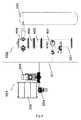
図1は、2つの主なサブシステム、すなわち前処理サブシステム101と、プロセス反応器への送込みサブシステム102とを有するバイオマス前処理システム100のブロック図を示す。前処理サブシステム101は、乾燥バイオマスを受け取る手段と、前記バイオマスの浸漬および粉砕手段、すなわちパルプを製造する手段と、前記パルプを送り出す圧送手段とを有している。本発明による送込み装置102は、圧力を大気圧より高く維持する加圧手段と、前記パルプの含水量を低減する脱水手段と、プロセス反応器に前記パルプを送り込む輸送手段とを有している。 FIG. 1 shows a block diagram of a
図2では、本発明によるプロセス反応器に物質を送り込む装置を含むバイオマス前処理システムの概略図を、さまざまな要素に関してさらに詳細に開示する。前処理サブシステム101では、バイオマスが、収集され、たとえばコンベア201により輸送され、浸漬タンク202内に導入される。浸漬タンク内では、水と藁等のバイオマスとが、手段、たとえば渦流203によって混合され、パルプになる。カッタ204、たとえば回転ディスクがパルプを粉砕し、ポンプ205、たとえば容積形ポンプがパルプを送込み装置102内に追い込む。送込み装置102は、パルプ用の入口および脱水ゾーン1と、パルプを液体で希釈/追加/洗浄する洗浄ゾーン2と、押圧ゾーン3と、減圧および輸送ゾーン4と、脱水されかつ洗浄されたパルプをプロセス反応器に送り込む送込みゾーン5とを備えている。 In FIG. 2, a schematic diagram of a biomass pretreatment system including an apparatus for feeding material into a process reactor according to the present invention is disclosed in more detail with respect to various elements. In the
送込み装置102において、導管206からのパルプ導入に続き、脱水ゾーン1において、押圧スクリュー等、脱水手段207により脱水が行われる。パルプから押し出された浸漬水は、導管208を通して収集され、水再循環ループの一部となり、かつ弁209および導管210を通して浸漬水として再利用され得る。脱水手段207は、パルプを脱水して洗浄ゾーン2に輸送し、そこでは、洗浄液、たとえば水が、導管211を通して導入され、かつ弁212によって調節される。押圧ゾーン3でパルプからさらに押し出された洗浄液は、導管213を通して収集される。前記液体が水である場合、これは、再利用のために浸漬水とともに収集される。浸漬水および洗浄水は、高圧で排出され、再利用の前にその固形分または塩分を低減するために濾過手段によってさらに処理され得る。圧力ゾーン3から、パルプは、輸送手段214、たとえば輸送スクリューによって減圧および輸送ゾーン4を通って、プロセス反応器215の前に送込みゾーン5に押しやられる。 In the
図に示す実施形態では、送込み装置102のプロセス圧力は、加圧手段216、たとえば送込み装置102の外部ハウジング(図示せず)に圧力を加える空気圧縮機によって確立される。しかしながら、加圧手段216を省略してもよく、加圧を、送込み装置102にパルプを押し入れるポンプ205によって行ってもよい。 In the illustrated embodiment, the process pressure of the
反応器の上流に、加圧手段216またはポンプ205によって誘導される高圧が存在することにより、反応器からのかつシステム内において上流の非常に高温の蒸気、アンモニアまたは概して化学物質および他の気体のバックフラッシュが妨げられる。送込み装置における圧力を調節することにより、送込み装置と反応器との圧力差、すなわち前記バックフラッシュを概して引き起こす差を回避することができる。 The presence of the high pressure induced by the pressurizing means 216 or pump 205 upstream of the reactor allows for very hot vapor, ammonia or generally chemicals and other gases from the reactor and upstream in the system. Backflush is prevented. By adjusting the pressure in the infeed device, the pressure difference between the infeed device and the reactor, that is, the difference that generally causes the backflush, can be avoided.
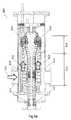
図3は、本発明の一実施形態による送込み装置102の詳細な断面図を示す。送込み装置は、パルプ用の入口および脱水ゾーン1と、パルプを液体により希釈/追加/洗浄する洗浄ゾーン2と、押圧ゾーン3と、輸送ゾーン4と、洗浄されかつ圧縮されたパルプをプロセス反応器に送り込む送込みゾーン5とを有する、管状ケーシング等の容器301を備えている。 FIG. 3 shows a detailed cross-sectional view of the
パルプは、導管302を通して脱水ゾーン1に導入され、かつ可変速モータ304によって動力が供給されるスクリュー型脱水装置303によって脱水される。スクリュー型脱水装置303は、一般的に、材料の塊を導管302から離れる略軸方向にかつ洗浄ゾーン2に向けて前進させるように配置されている。パルプから押し出される浸漬水は、導管305を通して排出され、たとえば濾過後にプロセスの第1のステップにおける浸漬水として再利用することができる水源を、高圧で提供する。スクリュー303によって搬送される脱水されたパルプを、洗浄ゾーン2において、洗浄液、たとえば真水で洗浄することができる。パルプの含水量を、導管306を通して制御された真水の追加によって調節することができる。スクリュー型脱水装置303は、パルプと洗浄水との有効な混合を提供する。追加の水は、押圧ゾーン3でさらに押し出され、再利用のために収集されるように穿孔307を通して排出される。概して、乾燥物質の含有量が6%である、導管302に入るパルプは、押圧ゾーン3においてその乾燥物質の含有量が25〜60%まで上昇する。押圧ゾーン3に続き、乾燥押圧されたパルプは、減圧および輸送ゾーン4において減圧され搬送スクリュー308によって小さいパルプ繊維になるように膨らまされる(fluffed up)。搬送スクリュー308は、可変速モータ309によって動力が供給され、膨らんだパルプを送りゾーン5内に輸送し、そこでパルプはプロセス反応器(図示せず)に送られる。 The pulp is dehydrated by a screw-
図3を参照すると、過酸化水素等の液体または気体化学物質を、任意に、導管310を介して減圧および輸送ゾーン内に、または導管311を通して送込みゾーンに導入することができる。 Referring to FIG. 3, a liquid or gaseous chemical such as hydrogen peroxide can optionally be introduced into the vacuum and transport zone via
送込み装置102の加圧を、パルプを導管302から送込み装置内に押し込むポンプ(図示せず)によって行うことができる。加圧を、1つまたは複数の二次ポンプ(図示せず)により導管312を通して提供してもよい。送込み装置102全体を、送込み装置102の外部ハウジング(図示せず)内部のこうした圧力を維持する加圧手段により、反応器内部の圧力よりも高い圧力または反応器内部の圧力に等しい圧力で加圧してもよい。 Pressurization of the
図4は、浸漬タンク202と、カッタ204と、容積形ポンプ205と、容積形ポンプ205と送込み装置102の接続部217と、プロセス反応器215とを含む、本発明の一実施形態によるさまざまな要素の断面図を示す。この実施形態では、送込み装置の容器301は、4つの部分に分割されるように示されており、それらを、脱水および洗浄ゾーン401、押圧ゾーン402、減圧および輸送ゾーン403および送込みゾーン404に対応する部分として特定することができる。任意の実施形態として図4を参照すると、送込み装置は、図4に示されるように別個の連結された容器の代りに、単一容器内部に上述したゾーンのすべてを含む。 FIG. 4 illustrates various embodiments according to the present invention, including a
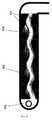
図5は、本発明による好ましい実施形態の断面図を示し、そこでは、材料の輸送がプログレッシブキャビティポンプによって行われる。図5に示す実施形態では、圧送要素は、単一らせん状のロータ502および二重らせん状のステータ501を備えている。単一らせん状のロータ502を金属材料から作製することができ、ステータ501を、エラストマー等の弾性ポリマー材料から作製することができる。ロータ502およびステータ501の特別な形状により、ロータの軸に沿って封止線が形成され、それが、静的状態または動的状態で維持される。ロータ502がステータ501内で回転すると、キャビティ504が材料入口503から材料出口に向かって前進し、材料を送込み装置を通ってプロセス反応器に向けて搬送する。 FIG. 5 shows a cross-sectional view of a preferred embodiment according to the present invention, in which material transport is performed by a progressive cavity pump. In the embodiment shown in FIG. 5, the pumping element comprises a single
図6は、本発明の別の実施形態による送込み装置600の断面図を示し、そこでは、材料の輸送は2つのスクリューシステムによって行われる。 FIG. 6 shows a cross-sectional view of a
この実施形態では、ケーシング609は、パルプ用の入口601と、脱水されたパルプ用の出口608と、パルプによって放出される水を排出する出口602とを備えている。パルプは、入口601を通って装置600内に導入され、輸送され、最初にスクリュー604を介して脱水される。この最初の脱水は、大部分、重力および圧力によって発生する。脱水中にパルプによって放出される水は、ネットシステム603を通り、出口602を通って排出される。排出された水を、先の実施形態に示したように、たとえば濾過後に再利用することができる。スクリュー604は、一般的に、材料の塊、たとえばパルプを、入口601から離れて略軸方向に脱水ゾーン605に向けて前進させるように配置され、脱水ゾーン605では、パルプはその輸送中に押圧される。輸送要素606を通るパルプは、その後、送込みスクリュー607と接触し、送込みスクリュー607は、材料の塊、たとえばパルプをスクリュー604の方向とは反対の略軸方向に前進させるように配置されている。 In this embodiment, the
送込みスクリュー607は、脱水されたパルプを、反応器入口(図示せず)の方向に出口608に向けて輸送する。スクリュー604および送込みスクリュー607は、たとえば歯車610上で回転することによりパルプを輸送する。 The
図6aは、送込み装置を通るパルプの流れを示す。パルプは、矢印611をたどって装置600に入り、矢印612をたどってスクリュー604を介して脱水/洗浄ゾーン613を通って輸送され脱水され、そこで、大部分重力および圧力により脱水される。パルプは、第2の脱水ゾーン614内に移動し、そこで、大部分圧力により脱水される。パルプは、矢印615をたどって、送込みスクリュー607を通って、矢印616に沿って装置の出口608に向けて送られる。パルプは、出口608から、矢印617をたどって反応器に送られる。 FIG. 6a shows the flow of pulp through the infeed device. The pulp follows the
本発明を、特定の実施形態に関連して説明したが、それを、提示した例に対していかなるようにも限定されるものとして解釈するべきではない。本発明の範囲を、添付の特許請求の範囲の組によって示す。特許請求の範囲の文脈では、「備えている、備える(comprising、comprises)」という用語は、あり得る他の要素またはステップを排除するものではない。また、「1つの(a、an)」等の指示を言及する場合、それは、複数を排除するものと解釈されるべきではない。図に示す要素に関連して請求項で参照符号を用いる場合、それもまた、本発明の範囲を限定するものと解釈されるべきではない。さらに、異なる請求項で述べられる個々の特徴を、有利に組み合わせることも可能であり、異なる請求項のこれらの特徴の言及は、特徴の組合せが可能でなくかつ有利でないことを意味しない。 Although the present invention has been described in connection with specific embodiments, it should not be construed as limiting in any way to the examples presented. The scope of the invention is indicated by the appended claims set. In the context of the claims, the term “comprising” does not exclude other possible elements or steps. Also, references to “one (a, an)” or the like should not be construed as excluding a plurality. Where reference signs are used in the claims in connection with elements shown in the figures, they should also not be construed as limiting the scope of the invention. Furthermore, individual features stated in different claims can also be advantageously combined, and references to these features in different claims do not imply that a combination of features is not possible and not advantageous.
1 脱水ゾーン
2 洗浄ゾーン
3 押圧ゾーン
4 減圧および輸送ゾーン
5 送込みゾーン
100 バイオマス前処理システム
101 前処理サブシステム
102 送込み装置
201 コンベア
202 浸漬タンク
203 渦流
204 カッタ
205 ポンプ
206 導管
207 脱水手段
208 導管
209 弁
210 導管
211 導管
212 弁
213 導管
214 輸送手段
215 プロセス反応器
216 加圧手段
217 接続部
301 容器
302 導管
303 スクリュー型脱水装置
304 可変速モータ
305 導管
306 導管
307 穿孔
308 搬送スクリュー
309 可変速モータ
310 導管
311 導管
312 導管
401 洗浄ゾーン
402 押圧ゾーン
403 減圧および搬送ゾーン
404 送込みゾーン
501 ステータ
502 ロータ
503 材料入口
504 キャビティ
600 送込み装置
601 入口
602 出口
603 ネットシステム
604 スクリュー
605 脱水ゾーン
606 輸送要素
607 スクリュー
608 出口
609 ケーシング
610 歯車
613 脱水/洗浄ゾーン
614 第2の脱水ゾーン1 Dehydration zone
2 Cleaning zone
3 Pressing zone
4 Depressurization and transport zone
5 Infeed zone
100 Biomass pretreatment system
101 Preprocessing subsystem
102 Infeed device
201 conveyor
202 immersion tank
203 Whirlpool
204 Cutter
205 pump
206 conduit
207 Dehydration means
208 conduit
209 valve
210 conduit
211 conduit
212 valves
213 conduit
214 means of transport
215 process reactor
216 Pressurizing means
217 connections
301 container
302 conduit
303 Screw type dehydrator
304 Variable speed motor
305 conduit
306 conduit
307 drilling
308 Conveying screw
309 Variable speed motor
310 conduit
311 conduit
312 conduit
401 Cleaning zone
402 Pressing zone
403 Depressurization and transfer zone
404 delivery zone
501 stator
502 rotor
503 Material inlet
504 cavity
600 feeding device
601 entrance
602 Exit
603 Net system
604 screw
605 Dehydration zone
606 Transportation elements
607 screw
608 Exit
609 casing
610 gear
613 Dehydration / washing zone
614 Second dewatering zone
Claims (29)
Translated fromJapanese前記送込み装置(102)が、
外部ハウジングと、
前記外部ハウジングの内部に収容されている容器(301)であって、前記バイオマス材料を前記容器(301)の内部に導入するための材料入口、及び前記バイオマス材料を前記反応器(215)の内部に送り込むための材料出口を備えている前記容器(301)と、
前記外部ハウジングの内部を加圧するための加圧手段であって、前記バイオマス材料が前記容器(301)内部にある時に加圧されるように、前記バイオマス材料を加圧するための加圧手段と、
前記バイオマス材料を前記材料入口から前記材料出口まで輸送して前記バイオマス材料を前記反応器(215)に送り込むための輸送手段(214)と、
前記容器(301)内部の、前記反応器(215)に送り込まれる前記バイオマス材料を脱水する手段と、
液体を前記容器(301)の外部に排出するための液体出口と、
を備えていることを特徴とする装置。An apparatus for producing a bio product from a biomass material, the apparatus comprising a feeding device (102) and a reactor (215), wherein the feeding device (102) is contained in a liquid Configured to feed the biomass material into the reactor (215);
The feeding device (102) is
An outer housing;
A container (301) housed inside the outer housing, the material inlet for introducing the biomass material into the container (301), and the biomass material inside the reactor (215) Said container (301) comprising a material outlet for feeding into
Pressurizing means for pressurizing the interior of the outer housing, the pressurizing means for pressurizing the biomass material so that it is pressurized when the biomass material is inside the container (301);
Transport means (214) for transporting the biomass material from the material inlet to the material outlet and feeding the biomass material into the reactor (215);
Means for dewatering the biomass material fed into the reactor (215) inside the vessel (301);
A liquid outlet for discharging liquid to the outside of the container (301);
A device characterized by comprising:
i)前処理サブシステム(101)において、前記バイオマス材料を収集し、輸送し、パルプにし、粉砕し、送込み装置(102)に送り出すステップと、
ii)液体に含まれる前記バイオマス材料を前記送込み装置(102)から、前記バイオマス材料の化学的構造および/または物理的構造が変化する反応器(215)に送り込むステップと、
を含み、
前記送込み装置(102)が、
外部ハウジングと、
前記外部ハウジングに収容されている容器(301)であって、前記バイオマス材料が内部に導入されるようにするための材料入口と、前記バイオマス材料が前記反応器(215)に送り込まれるようにするための材料出口とを備えた前記容器(301)と、
前記外部ハウジングを加圧するための加圧手段であって、前記バイオマス材料が前記容器(301)内部にある時に加圧されるように、前記バイオマス材料を加圧する加圧手段と、
前記バイオマス材料を前記材料入口から前記材料出口まで輸送するための輸送手段(214)であって、それにより、前記バイオマス材料が前記反応器(215)に送り込まれる、前記輸送手段(214)と、
前記容器(301)内部の、前記反応器(215)に送り込まれる前記バイオマス材料を脱水するための手段と、
液体を前記容器(301)の外部に排出するための液体出口と、
を備えている前記方法において、
前記加圧手段により、前記容器(301)内部に、前記反応器(215)内部の圧力よりも高い圧力または少なくとも前記反応器(215)内部の圧力に等しい圧力が提供され、前記外部ハウジングの内部に作用する圧力が、前記反応器(215)の内部の圧力より高いか、又は等しいことを特徴とする方法。A method for producing a bio product from a biomass material, the method comprising:
i) in the pretreatment subsystem (101), collecting, transporting, pulping, pulverizing and delivering the biomass material to a feeding device (102);
ii) feeding the biomass material contained in a liquid from the feeding device (102) to a reactor (215) in which the chemical structure and / or physical structure of the biomass material changes;
Including
The feeding device (102) is
An outer housing;
A container (301) housed in the outer housing, wherein a material inlet for allowing the biomass material to be introduced therein, and the biomass material being fed into the reactor (215); Said container (301) with a material outlet for
Pressurizing means for pressurizing the outer housing, pressurizing means for pressurizing the biomass material such that the biomass material is pressurized when it is inside the container (301);
Transport means (214) for transporting the biomass material from the material inlet to the material outlet, whereby the biomass material is fed into the reactor (215);
Means for dehydrating the biomass material fed into the reactor (215) inside the vessel (301);
A liquid outlet for discharging liquid to the outside of the container (301);
In the method comprising:
The pressurizing means provides the container (301) with a pressure higher than the pressure inside the reactor (215) or at least equal to the pressure inside the reactor (215). The pressure acting on the reactor is higher than or equal to the pressure inside the reactor (215).
Applications Claiming Priority (3)
| Application Number | Priority Date | Filing Date | Title |
|---|---|---|---|
| DKPA200900047 | 2009-01-13 | ||
| DKPA200900047 | 2009-01-13 | ||
| PCT/DK2010/050003WO2010081476A1 (en) | 2009-01-13 | 2010-01-12 | Method and apparatus for in-feeding of matter to a process reactor |
Publications (2)
| Publication Number | Publication Date |
|---|---|
| JP2012514972A JP2012514972A (en) | 2012-07-05 |
| JP5759384B2true JP5759384B2 (en) | 2015-08-05 |
Family
ID=41059713
Family Applications (1)
| Application Number | Title | Priority Date | Filing Date |
|---|---|---|---|
| JP2011544788AExpired - Fee RelatedJP5759384B2 (en) | 2009-01-13 | 2010-01-12 | Method and apparatus for feeding substances into a process reactor |
Country Status (14)
| Country | Link |
|---|---|
| US (1) | US8871061B2 (en) |
| EP (1) | EP2398958B1 (en) |
| JP (1) | JP5759384B2 (en) |
| CN (2) | CN102272378B (en) |
| AU (1) | AU2010205965B2 (en) |
| BR (1) | BRPI1006140A2 (en) |
| CA (1) | CA2749184C (en) |
| DK (1) | DK2398958T3 (en) |
| ES (1) | ES2406695T3 (en) |
| MX (1) | MX2011006888A (en) |
| MY (1) | MY159717A (en) |
| RU (1) | RU2540886C2 (en) |
| WO (1) | WO2010081476A1 (en) |
| ZA (1) | ZA201104719B (en) |
Families Citing this family (32)
| Publication number | Priority date | Publication date | Assignee | Title |
|---|---|---|---|---|
| US9499635B2 (en) | 2006-10-13 | 2016-11-22 | Sweetwater Energy, Inc. | Integrated wood processing and sugar production |
| US9410216B2 (en) | 2010-06-26 | 2016-08-09 | Virdia, Inc. | Sugar mixtures and methods for production and use thereof |
| IL206678A0 (en) | 2010-06-28 | 2010-12-30 | Hcl Cleantech Ltd | A method for the production of fermentable sugars |
| IL207329A0 (en) | 2010-08-01 | 2010-12-30 | Robert Jansen | A method for refining a recycle extractant and for processing a lignocellulosic material and for the production of a carbohydrate composition |
| IL207945A0 (en) | 2010-09-02 | 2010-12-30 | Robert Jansen | Method for the production of carbohydrates |
| PT106039A (en) | 2010-12-09 | 2012-10-26 | Hcl Cleantech Ltd | PROCESSES AND SYSTEMS FOR PROCESSING LENHOCELLULOSIC MATERIALS AND RELATED COMPOSITIONS |
| GB2524906B8 (en) | 2011-04-07 | 2016-12-07 | Virdia Ltd | Lignocellulose conversion processes and products |
| US9617608B2 (en) | 2011-10-10 | 2017-04-11 | Virdia, Inc. | Sugar compositions |
| US8765430B2 (en) | 2012-02-10 | 2014-07-01 | Sweetwater Energy, Inc. | Enhancing fermentation of starch- and sugar-based feedstocks |
| WO2013155496A1 (en) | 2012-04-13 | 2013-10-17 | Sweetwater Energy, Inc. | Methods and systems for saccharification of biomass |
| US8563277B1 (en) | 2012-04-13 | 2013-10-22 | Sweetwater Energy, Inc. | Methods and systems for saccharification of biomass |
| DE102012015908A1 (en)* | 2012-08-10 | 2014-05-15 | Jan Kuclo | Continuous biochemical conversion of biomass for producing biogas with large optimization of the conversion method into narrow boundaries provided by the surrounding, comprises e.g. preparing and heating the biomass into a charging lock |
| GB201215505D0 (en) | 2012-08-31 | 2012-10-17 | C5 Labs Aps | Process for the production of ethanol |
| US9333468B2 (en) | 2012-09-24 | 2016-05-10 | Abengoa Bioenergy New Technologies, Llc | Soak vessels and methods for impregnating biomass with liquid |
| US9115214B2 (en) | 2012-09-24 | 2015-08-25 | Abengoa Bioenergy New Technologies, Llc | Methods for controlling pretreatment of biomass |
| US9809867B2 (en) | 2013-03-15 | 2017-11-07 | Sweetwater Energy, Inc. | Carbon purification of concentrated sugar streams derived from pretreated biomass |
| RS59184B1 (en) | 2014-09-19 | 2019-10-31 | Versalis Spa | Continuous process for treating a lignocellulosic biomass |
| PT3194653T (en) | 2014-09-19 | 2019-06-11 | Versalis Spa | Continuous process for treating a lignocellulosic biomass |
| CN104328701A (en)* | 2014-10-30 | 2015-02-04 | 翟顺利 | Paper medium pulping equipment |
| CA2969840A1 (en) | 2014-12-09 | 2016-06-16 | Sweetwater Energy, Inc. | Rapid pretreatment |
| US11078548B2 (en) | 2015-01-07 | 2021-08-03 | Virdia, Llc | Method for producing xylitol by fermentation |
| EP3054051A1 (en)* | 2015-02-09 | 2016-08-10 | BETA RENEWABLES S.p.A. | Process to transfer a ligno-cellulosic feedstock |
| WO2017088061A1 (en) | 2015-11-25 | 2017-06-01 | Iogen Energy Corporation | System and method for cooling pretreated biomass |
| PL3192626T3 (en)* | 2016-01-12 | 2018-11-30 | SWISS KRONO Tec AG | Method for the treatment of wood dust and assembly for the same |
| CA3053773A1 (en) | 2017-02-16 | 2018-08-23 | Sweetwater Energy, Inc. | High pressure zone formation for pretreatment |
| SE541532C2 (en)* | 2018-03-12 | 2019-10-29 | Valmet Oy | Arrangement and method for transporting pulp from one process stage to a subsequent process stage |
| CN109971612B (en)* | 2019-04-03 | 2023-06-23 | 方旭华 | Pressing and pushing door linkage feeding power device |
| WO2021133733A1 (en) | 2019-12-22 | 2021-07-01 | Sweetwater Energy, Inc. | Methods of making specialized lignin and lignin products from biomass |
| US20230063353A1 (en)* | 2020-01-21 | 2023-03-02 | Technische Universität Dortmund | Rotating-screw drying reactor |
| SE545274C2 (en)* | 2020-06-08 | 2023-06-13 | Valmet Oy | A pre-hydrolysis pressure vessel system comprising a cleaning arrangement |
| GB202103185D0 (en)* | 2021-03-08 | 2021-04-21 | Trifilon Ab | Reaction chamber, processing system and processsing method |
| CN113445349B (en)* | 2021-07-14 | 2022-12-09 | 龙口玉龙纸业有限公司 | Efficient environment-friendly papermaking equipment and papermaking process thereof |
Family Cites Families (27)
| Publication number | Priority date | Publication date | Assignee | Title |
|---|---|---|---|---|
| DE1045221B (en) | 1954-03-30 | 1958-11-27 | Hercules Powder Co Ltd | Method and device for forming and comminuting a pressure-resistant lump of cellulose material |
| GB1590704A (en) | 1976-11-23 | 1981-06-10 | Defibrator Ab | Method end device for the continuous production of pulp from fibrous lignocellulosic materials |
| SE422340B (en) | 1978-10-18 | 1982-03-01 | Defibrator Ab | SET AND DEVICE FOR MANUFACTURING MECHANICAL MASS FROM CHEESE OF LIGNOCELLULOSIC MATERIAL |
| FI810523L (en)* | 1980-02-23 | 1981-08-24 | Franz Johann Reitter | REQUIREMENTS FOR CONTAINING CONTAINER HYDROLYS AV CELLULOSAHALTIG VAEXT-BIOSUBSTANS FOER UTVINNING AV SOCKER |
| SE429874B (en)* | 1982-02-16 | 1983-10-03 | Sunds Defibrator | SET AND DEVICE FOR MANUFACTURING FIBER MASS AND LIGNOCELLULOSALLY MATERIAL |
| SU1285091A1 (en)* | 1984-02-28 | 1987-01-23 | Архангельский лесотехнический институт им.В.В.Куйбышева | Installation for producing fibrous wood mass |
| NO159494C (en)* | 1986-10-23 | 1989-01-04 | Kvaerner Eureka As | PROCEDURE BY BLACKING CELLULOSMASS OR FRACTION THEREOF, PLANT FOR USE BY IMPLEMENTING THE PROCEDURE. |
| US4720976A (en) | 1986-12-30 | 1988-01-26 | Myung Kyoon Kim | Method of power generation and its apparatus utilizing gravitation force and buoyancy |
| RU2099456C1 (en)* | 1988-06-24 | 1997-12-20 | Фонген Сигурд | Method and installation for preparing fibrous pulp to manufacture paper, paperboard, fiberboards, and other produce containing wood and/or other vegetable fibers |
| SE461919B (en)* | 1988-08-30 | 1990-04-09 | Cellwood Machinery Ab | SET FOR TREATMENT OF TREASURY FIBER, SEPARATELY CONTAINING RECOVERY PAPER, AND DISPERSE BEFORE IMPLEMENTATION OF THE PROCEDURE |
| FR2670512A1 (en)* | 1990-12-17 | 1992-06-19 | Int Patents Corp | System for feeding annual plants or wood chips to a continuous cooking reactor under pressure, intended for the production of cellulose pulp |
| FI92250C (en)* | 1992-03-30 | 1994-10-10 | Kone Oy | Method and apparatus for feeding a substance to a pressurized space |
| US5589599A (en)* | 1994-06-07 | 1996-12-31 | Mcmullen; Frederick G. | Pyrolytic conversion of organic feedstock and waste |
| CN1089112C (en)* | 1997-03-18 | 2002-08-14 | 2B公开股份有限公司 | Method for using plant biomass and screw extruder for carrying out said method |
| US6105275A (en)* | 1998-03-19 | 2000-08-22 | Sepredyne Corporation | Continuous rotary vacuum retort apparatus and method of use |
| CA2339002C (en) | 1998-08-03 | 2009-04-07 | Stake Technology Ltd. | Method and apparatus for feeding a mass of particulate or fibrous material |
| US6733662B2 (en)* | 2001-02-23 | 2004-05-11 | V.A.I. Ltd. | Methods and apparatus for biological treatment of waste waters |
| BR0211834B1 (en)* | 2001-08-11 | 2012-09-04 | method and apparatus for transferring a particulate product between two zones with different pressures. | |
| CN1277984C (en)* | 2002-05-30 | 2006-10-04 | 徐守才 | Closed and combined FGSB wheat (rice) straw material preparing system |
| CN100585068C (en)* | 2004-07-01 | 2010-01-27 | 天津轻工业机械厂设计研究所 | Long bast fiber raw material semi-chemical mechanical pulp continuous cooking method and device |
| US7300540B2 (en)* | 2004-07-08 | 2007-11-27 | Andritz Inc. | Energy efficient TMP refining of destructured chips |
| BRPI0419060A (en)* | 2004-08-31 | 2007-12-26 | Biotech Progress A S | method and devices for continuous processing of renewable raw materials |
| DE102005048958B4 (en) | 2005-10-13 | 2007-08-09 | Glunz Ag | Method and device for obtaining wood fibers from wood chips |
| EP1984514A4 (en)* | 2006-01-27 | 2010-09-01 | Univ Massachusetts | SYSTEMS AND METHODS FOR OBTAINING BIOFUELS AND RELATED SUBSTANCES |
| JP2008182925A (en)* | 2007-01-29 | 2008-08-14 | Toshiba Corp | Bioethanol production method and apparatus |
| US20080277082A1 (en)* | 2007-05-07 | 2008-11-13 | Andritz Inc. | High pressure compressor and steam explosion pulping method |
| US8328947B2 (en)* | 2008-08-29 | 2012-12-11 | Iogen Energy Corporation | Method for low water hydrolysis or pretreatment of polysaccharides in a lignocellulosic feedstock |
- 2010
- 2010-01-12MXMX2011006888Apatent/MX2011006888A/enactiveIP Right Grant
- 2010-01-12AUAU2010205965Apatent/AU2010205965B2/ennot_activeCeased
- 2010-01-12ESES10700150Tpatent/ES2406695T3/enactiveActive
- 2010-01-12EPEP10700150Apatent/EP2398958B1/ennot_activeNot-in-force
- 2010-01-12MYMYPI2011003013Apatent/MY159717A/enunknown
- 2010-01-12JPJP2011544788Apatent/JP5759384B2/ennot_activeExpired - Fee Related
- 2010-01-12CACA2749184Apatent/CA2749184C/enactiveActive
- 2010-01-12BRBRPI1006140Apatent/BRPI1006140A2/ennot_activeApplication Discontinuation
- 2010-01-12CNCN201080004126.6Apatent/CN102272378B/ennot_activeExpired - Fee Related
- 2010-01-12RURU2011134063/12Apatent/RU2540886C2/enactive
- 2010-01-12USUS13/144,271patent/US8871061B2/enactiveActive
- 2010-01-12DKDK10700150.5Tpatent/DK2398958T3/enactive
- 2010-01-12CNCN201410315507.6Apatent/CN104047195A/enactivePending
- 2010-01-12WOPCT/DK2010/050003patent/WO2010081476A1/enactiveApplication Filing
- 2011
- 2011-06-24ZAZA2011/04719Apatent/ZA201104719B/enunknown
Also Published As
| Publication number | Publication date |
|---|---|
| BRPI1006140A2 (en) | 2016-02-23 |
| CN104047195A (en) | 2014-09-17 |
| ZA201104719B (en) | 2012-03-28 |
| MY159717A (en) | 2017-01-31 |
| CA2749184C (en) | 2017-07-04 |
| CN102272378B (en) | 2015-02-18 |
| US8871061B2 (en) | 2014-10-28 |
| RU2011134063A (en) | 2013-02-20 |
| JP2012514972A (en) | 2012-07-05 |
| WO2010081476A1 (en) | 2010-07-22 |
| CA2749184A1 (en) | 2010-07-22 |
| EP2398958A1 (en) | 2011-12-28 |
| AU2010205965A1 (en) | 2011-07-21 |
| US20110275860A1 (en) | 2011-11-10 |
| EP2398958B1 (en) | 2013-02-13 |
| MX2011006888A (en) | 2011-09-06 |
| AU2010205965B2 (en) | 2014-12-04 |
| DK2398958T3 (en) | 2013-05-21 |
| RU2540886C2 (en) | 2015-02-10 |
| ES2406695T3 (en) | 2013-06-07 |
| CN102272378A (en) | 2011-12-07 |
Similar Documents
| Publication | Publication Date | Title |
|---|---|---|
| JP5759384B2 (en) | Method and apparatus for feeding substances into a process reactor | |
| CN107858386B (en) | Method for processing lignocellulose-containing biomass | |
| RU2461678C2 (en) | System and method of preliminary extraction of hemicellulose by continuous prehydrolysis and process | |
| US20110281298A1 (en) | Method and apparatus to extracted and reduce dissolved hemi-cellulosic solids in biomass following pre-hydrolysis | |
| CA2732084C (en) | Method for low water hydrolysis or pretreatment of polysaccharides in a lignocellulosic feedstock | |
| US10047408B2 (en) | Arrangement and system for a treatment process | |
| JP7402816B2 (en) | How to process lignocellulosic biomass | |
| RU2667868C1 (en) | Method for preliminary processing of lignocellulose biomass raw material | |
| JP3496872B2 (en) | Method and system for supplying finely divided fibrous material | |
| AU2022304349B2 (en) | Solid fuel production system and solid fuel production method | |
| US20170175328A1 (en) | Method and apparatus for pumping sawdust feed in a sawdust pulping system | |
| SE538514C2 (en) | Method for producing a sludge mixture in a pulp mill |
Legal Events
| Date | Code | Title | Description |
|---|---|---|---|
| A621 | Written request for application examination | Free format text:JAPANESE INTERMEDIATE CODE: A621 Effective date:20121102 | |
| A711 | Notification of change in applicant | Free format text:JAPANESE INTERMEDIATE CODE: A711 Effective date:20130812 | |
| A521 | Request for written amendment filed | Free format text:JAPANESE INTERMEDIATE CODE: A821 Effective date:20130812 | |
| A977 | Report on retrieval | Free format text:JAPANESE INTERMEDIATE CODE: A971007 Effective date:20131217 | |
| A131 | Notification of reasons for refusal | Free format text:JAPANESE INTERMEDIATE CODE: A131 Effective date:20140107 | |
| A601 | Written request for extension of time | Free format text:JAPANESE INTERMEDIATE CODE: A601 Effective date:20140407 | |
| A602 | Written permission of extension of time | Free format text:JAPANESE INTERMEDIATE CODE: A602 Effective date:20140414 | |
| A521 | Request for written amendment filed | Free format text:JAPANESE INTERMEDIATE CODE: A523 Effective date:20140704 | |
| A131 | Notification of reasons for refusal | Free format text:JAPANESE INTERMEDIATE CODE: A131 Effective date:20150209 | |
| A521 | Request for written amendment filed | Free format text:JAPANESE INTERMEDIATE CODE: A523 Effective date:20150414 | |
| TRDD | Decision of grant or rejection written | ||
| A01 | Written decision to grant a patent or to grant a registration (utility model) | Free format text:JAPANESE INTERMEDIATE CODE: A01 Effective date:20150511 | |
| A61 | First payment of annual fees (during grant procedure) | Free format text:JAPANESE INTERMEDIATE CODE: A61 Effective date:20150605 | |
| R150 | Certificate of patent or registration of utility model | Ref document number:5759384 Country of ref document:JP Free format text:JAPANESE INTERMEDIATE CODE: R150 | |
| LAPS | Cancellation because of no payment of annual fees |