JP5759205B2 - Roof mount support - Google Patents
Roof mount supportDownload PDFInfo
- Publication number
- JP5759205B2 JP5759205B2JP2011043692AJP2011043692AJP5759205B2JP 5759205 B2JP5759205 B2JP 5759205B2JP 2011043692 AJP2011043692 AJP 2011043692AJP 2011043692 AJP2011043692 AJP 2011043692AJP 5759205 B2JP5759205 B2JP 5759205B2
- Authority
- JP
- Japan
- Prior art keywords
- roof
- tile
- locking
- support
- water
- Prior art date
- Legal status (The legal status is an assumption and is not a legal conclusion. Google has not performed a legal analysis and makes no representation as to the accuracy of the status listed.)
- Active
Links
Images


Classifications
- Y—GENERAL TAGGING OF NEW TECHNOLOGICAL DEVELOPMENTS; GENERAL TAGGING OF CROSS-SECTIONAL TECHNOLOGIES SPANNING OVER SEVERAL SECTIONS OF THE IPC; TECHNICAL SUBJECTS COVERED BY FORMER USPC CROSS-REFERENCE ART COLLECTIONS [XRACs] AND DIGESTS
- Y02—TECHNOLOGIES OR APPLICATIONS FOR MITIGATION OR ADAPTATION AGAINST CLIMATE CHANGE
- Y02B—CLIMATE CHANGE MITIGATION TECHNOLOGIES RELATED TO BUILDINGS, e.g. HOUSING, HOUSE APPLIANCES OR RELATED END-USER APPLICATIONS
- Y02B10/00—Integration of renewable energy sources in buildings
- Y02B10/10—Photovoltaic [PV]
- Y—GENERAL TAGGING OF NEW TECHNOLOGICAL DEVELOPMENTS; GENERAL TAGGING OF CROSS-SECTIONAL TECHNOLOGIES SPANNING OVER SEVERAL SECTIONS OF THE IPC; TECHNICAL SUBJECTS COVERED BY FORMER USPC CROSS-REFERENCE ART COLLECTIONS [XRACs] AND DIGESTS
- Y02—TECHNOLOGIES OR APPLICATIONS FOR MITIGATION OR ADAPTATION AGAINST CLIMATE CHANGE
- Y02E—REDUCTION OF GREENHOUSE GAS [GHG] EMISSIONS, RELATED TO ENERGY GENERATION, TRANSMISSION OR DISTRIBUTION
- Y02E10/00—Energy generation through renewable energy sources
- Y02E10/50—Photovoltaic [PV] energy
Landscapes
- Roof Covering Using Slabs Or Stiff Sheets (AREA)
Description
Translated fromJapanese本発明は、屋根上に太陽光発電パネル等を取り付けるための架台を支持する屋根上架台の支持具に関する。 The present invention relates to a support for a roof mount that supports a mount for attaching a photovoltaic power generation panel or the like on the roof.
太陽光発電パネルは、屋根上架台を用いて住宅等の瓦屋根の上部に設置される。
この屋根上架台は、バー材等を組み合せて架台を構成し、この架台を支持具を介して屋根上に固定し、架台の上部に太陽光発電パネルを取り付ける。A photovoltaic power generation panel is installed on the upper part of a tile roof such as a house using a roof mount.
This on-roof gantry comprises a gantry by combining bars and the like, this gantry is fixed on the roof via a support, and a photovoltaic power generation panel is attached to the upper part of the gantry.
例えば特許文献1には、図12に示すように、瓦屋根板100に固定するスタンド102(支持具)を使用したソーラー屋根板104の取付構造の開示がある。
上記スタンド102は、瓦屋根板100の水下側端縁106にスタンド102の水下側部材107の水下係止部108を係止し、瓦屋根板100の水上側端縁110に水上側部材111の水上係止部112を係止しながら、接合部114と水上側接合部116とを固着具118により固着するものである。上記スタンド102には、横材120を介してガッター材122を取り付け、ガッター材122間にソーラー屋根板104を固定する。For example,
In the
また、特許文献2には屋根上取り付け金具の記載があり、この金具は台座と可動体とからなり、台座には屋根面載置部と屋根面載置部の左右が立ち上げられた立ち上げ部とが形成され、可動体には、上面部と側壁部と屋根材に押圧される押圧部とが形成され、可動体が固定具を介して回動可能に組み合わされたものである。 Further,
さて、上記特許文献1のスタンド102は、瓦屋根板100の水下側端縁106と水上側端縁110とにそれぞれ係止して用いる形態であるため、全体に長く、また取付けの際には、瓦屋根板100を上方に持ち上げ、瓦屋根間にスタンド102の水上側部材111を水上係止部112側より挿入し、瓦屋根板の水上側端縁110に係止するものであるため、瓦屋根板100の持ち上げによる瓦屋根板の破損、或いは葺いた瓦屋根板のずれ等の支障を生じることが懸念され、また施工性も悪いという問題がある。 Now, since the
また、特許文献2の取り付け金具は、可動体を回動させ、屋根材の軒側ハゼ部を挟んでナットで押圧保持する構造であるため、金具が大型となり機構も複雑で加工性、生産性に欠け、施工にも手間取るという問題がある。 In addition, the mounting bracket of
本発明は上記問題点を解決するためになされたものであり、屋根瓦に容易かつ迅速に取り付けられて施工性に優れ、また加工が容易で生産性にも優れた屋根上架台の支持具を提供することを目的とする。 The present invention has been made in order to solve the above-described problems, and is a support for a roof mount that is easily and quickly attached to a roof tile, has excellent workability, is easy to process, and has excellent productivity. The purpose is to provide.
以上の技術的課題を解決するため、本発明に係る屋根上架台の支持具は、図1,2等に示すように、屋根斜面に葺かれた前段の瓦4に載置されるとともに、この前段の瓦4とその水上側に連ねて葺かれる後段の瓦6との間に一部が差し込まれる台座部材10と、この台座部材10の上部に固定される固定部42、及びこの固定部42の水上側に形成され上記後段の瓦6の上面部を押える押え部38からなる押え部材12と、上記押え部材12の固定部42の上部に取り付けられる取付部46、及びこの取付部46の上側に形成され屋根上架台を支持する受け部50からなる受部材14とを有し、止着具16,17を用いて上記台座部材10、上記押え部材12及び上記受部材14を一体に締結するとともに、上記後段の瓦6を上記台座部材10と上記押え部材12とで挟持して屋根斜面上に固定する構成である。 In order to solve the above technical problems, the roof mount support according to the present invention is placed on the
本発明に係る屋根上架台の支持具は、上記台座部材10の水上側に係止片部32を形成し、この係止片部32を上記後段の瓦6の水下側縁部25の裏面に設けられた係止凸部68に係止させる構成である。 The support for the roof mount according to the present invention forms a
本発明に係る屋根上架台の支持具は、上記押え部材12の固定部42に水上水下向きに長い長孔部44を設け、この長孔部44に上記止着具16,17を挿通させて、上記台座部材10に対する上記押え部材12の位置を調節可能とした構成である。 The support device for the roof mount according to the present invention is provided with a
本発明に係る屋根上架台の支持具は、長尺状の基体部56の水上側に横向きに形成される係止部58、及び上記基体部56の水下側に形成される連結部60からなる一対の係止部材18,19を用い、上記前段の瓦4と上記後段の瓦6との間に、上記両係止部材の係止部58,58をそれぞれ横向きに倒して差し込み、さらに上記基体部56を回して上記係止部58を下方に向けるとともに上記前段の瓦4の水上側縁部24にそれぞれ係止させる一方、上記両係止部材の連結部60,60同士を上記台座部材10の水下側で締結するとともに、上記両係止部材18,19をそれぞれ上記台座部材10或いは上記押え部材12の両側部に保持させた構成である。 The roof mount support according to the present invention includes a
本発明に係る屋根上架台の支持具によれば、前段の瓦に載置される台座部材、後段の瓦を押える押え部材、及び屋根上架台を支持する受部材を有し、これらを一体に締結するとともに後段の瓦を台座部材と押え部材とで挟持して屋根斜面上に固定する構成を採用したから、屋根斜面に葺かれた瓦に容易かつ迅速に取り付けられて施工性に優れ、また瓦同士の隙間に差し込んで後段の瓦に挟持し保持させる形態であるため、瓦の破損或いは葺いた瓦のずれ等が防止でき、さらには加工が容易で生産性にも優れるという効果を奏する。 According to the support for the roof mount according to the present invention, it has a pedestal member placed on the front tile, a holding member for pressing the back tile, and a receiving member for supporting the roof mount, and these are integrated. Since it is fastened and the rear tile is sandwiched between the base member and the holding member and fixed on the roof slope, it can be easily and quickly attached to the roof sloped roof tile, and it has excellent workability. Since it is inserted into the gap between the roof tiles and held between the roof tiles, the roof tiles can be prevented from being damaged or crushed tiles can be prevented from shifting, and further, the processing is easy and the productivity is excellent.
本発明に係る屋根上架台の支持具によれば、台座部材に形成した係止片部を後段の瓦の係止凸部に係止させる構成としたから、後段の瓦に保持される支持具が、さらに係止によってより強固に保持されるという効果がある。 According to the support for the roof mount according to the present invention, since the locking piece formed on the base member is locked to the locking projection of the back tile, the support held by the back tile. However, there is an effect that it is held more firmly by the locking.
本発明に係る屋根上架台の支持具によれば、押え部材に長孔部を設け、台座部材に対する押え部材の位置を調節可能とした構成としたから、後段の瓦に対する押え部材の保持位置の調整が簡単に行えるという効果がある。 According to the support for the roof mount according to the present invention, the holding member is provided with the long hole portion and the position of the holding member with respect to the base member can be adjusted. There is an effect that adjustment can be performed easily.
本発明に係る屋根上架台の支持具によれば、一対の係止部材の係止部を前段の瓦に係止させ、連結部同士を台座部材の水下側で締結して保持させた構成を採用したから、支持具が前段の瓦にも係止されるため、さらに移動(水下側への)が阻止され、支持具の保持固定がより確実に行え、また係止部材は瓦同士の間の隙間に差し込んで係止させる構成であるため、瓦の破損或いは葺いた瓦のずれ等が防止できるという効果がある。 According to the support for the roof mount according to the present invention, the structure in which the locking portions of the pair of locking members are locked to the roof tile in the previous stage and the connecting portions are fastened and held on the underwater side of the base member. Since the support is also locked to the roof tile in the previous stage, further movement (to the underwater side) is prevented, and the support tool can be held and fixed more reliably. Therefore, it is possible to prevent the roof tile from being damaged or the roof tile from shifting.
以下、本発明に係る屋根上架台の支持具の実施の形態を図面に基づいて説明する。
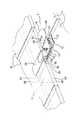
図1は、上記屋根上架台の支持具2を屋根上の瓦に取り付けた状態を示す。
この支持具2は、屋根斜面の水下側に葺かれた前段の瓦4と、この前段の瓦4の水上側に重ねて葺かれた後段の瓦6とにわたって取り付けられる。上記後段の瓦6は、上記前段の瓦4の水上側部位の上部にこの後段の瓦6の水下側部位の一部を重ねて葺いたものである。DESCRIPTION OF EMBODIMENTS Hereinafter, embodiments of a support for a roof mount according to the present invention will be described with reference to the drawings.
FIG. 1 shows a state in which the
The
上記支持具2は、前段の瓦4の上面部に載置される台座部材10、後段の瓦6の水下側部位の上面部22を押える押え部材12、及び下記屋根上架台1を支持する受部材14を有している。これら台座部材10、押え部材12及び受部材14は、止着具としてのボルト16、ナット17により締結され一体化されている。上記台座部材10、押え部材12及び受部材14は、何れも鋼板加工により製造したものである。 The
さらに上記支持具2は、台座部材10の両側に配置され、上記前段の瓦4の水上側縁部24にそれぞれ係止させる形状の一対の係止部材18,19を有している。
これら係止部材18,19は、支持具2を屋根上へ保持固定する機能を強化するものである。Further, the
These locking
したがって上記支持具2は、図2に示す支持具2の本体3となる基本形態と、これに上記係止部材18,19を加えて支持具2の屋根上への固定構造を強化した形態とがある。
上記支持具2は、上記基本形態及び補強形態の何れの形態であっても、屋根上架台の支持具としての機能を果すことができる。
以下、屋根上架台の支持具2については、便宜上上記強化した形態を中心に説明する。Therefore, the
The
Hereinafter, the
図3は上記支持具2の分解斜視図である。
同図に示すように、上記台座部材10は、基部26の水下側には台支持部28がまた水上側には台支持部30が、それぞれ下方に向けて段状に形成されている。またこの台支持部30の先端部には、上方に屈曲形成された係止片部32が設けられている。
上記基部26及び台支持部28には、何れも中央部に凸条(水上水下向き)のボス部34が形成されている。また、基部26の中央には孔部36が設けられている。FIG. 3 is an exploded perspective view of the
As shown in the figure, the
The
上記押え部材12は、中間部に一段上がった立上段部40が形成された長尺板状材であり、上記立上段部40の上段の水上側には平坦な押え部38が形成され、また下段の水下側には固定部42が形成されている。 The
上記固定部42には、水下側寄りの位置に一段下がった段部を経て延長部39が形成され、また固定部42の左右部には下方に屈曲したフランジ部43,43が形成されている。上記フランジ部43,43は、上記台座部材10の基部26の左右部位を内部に保持し、台座部材10と押え部材12との一体化が図られる。
また、固定部42から押え部38の一部にかけて中央部に凸条(水上水下向き)のボス部41が形成されている。さらに、固定部42の中央部には水上水下向きに長い長孔部44が形成され、上記台座部材10に対する押え部材12の位置決めが行えるようにしている。The fixed
Further, a
上記受部材14は板材を断面Z状に屈曲形成した形状であり、下部の取付部46、この取付部46の端部から上方に直角に立設形成された立上部48、及びこの立上部48の上端部から横向きに形成された平坦な受け部50からなる。上記取付部46には、中央部に孔部54が形成されている。
また、上記立上部48の中央部から受け部50にかけて溝状に切り欠かれた第一の溝部52が形成され、また受け部50にはこの第一の溝部52から連続して第二の溝部53が形成されている。上記第一の溝部52は、第二の溝部53よりも溝幅が大きく(略2倍)形成されている。The receiving
A
上記係止部材18,19は、2つを一組(一対)として使用するものであり、係止部材19は係止部材18とは左右対称な形状である。
図4にも示すように上記係止部材18は、細長い(断面円形)金属を屈曲等の加工をしたものであり、長尺棒状の基体部56、この基体部56の水上側に横向きに形成される係止部58、及び上記基体部56の水下側に形成される連結部60からなる。The locking
As shown in FIG. 4, the locking
上記係止部58は、基体部56から直角に屈曲形成され、さらに先部近傍には係止片66が内向きに屈曲形成されている。また、上記連結部60は、基体部56から直角に連結基部61が屈曲形成され、さらに締結部62がL状(90°)に屈曲形成された形状である。この締結部62は、偏平な形状であり中央部には孔部64が設けられている。
上記係止部58と上記連結部60の連結基部61とがなす角度は、上記基体部56の軸中心を基準にした場合90°より大きく(10°程度)形成されている(ここでは101°)。
係止部材19は、係止部材18とは左右対称な点を除き、各部の基本的な形状は同様である。係止部材18,19は、材料にステンレス鋼(SUS)を使用している。The locking
The angle formed by the locking
The locking
上記前段の瓦4及び後段の瓦6等の屋根瓦は何れも形状は同じであり、偏平な矩形状の屋根瓦である。また、これら瓦4,6等には、水下側縁部25の裏面に下方に突出した係止凸部68が形成され、また瓦4,6の裏面中央部には水上水下向きに溝状に窪んだ裏溝部70が形成されている。 The roof tiles such as the
ここで、上記屋根上架台の支持具2の使用形態について説明する。
先ず、葺いた屋根瓦に支持具2を取り付ける手順について説明する。
上記支持具2は、予め台座部材10、押え部材12及び受部材14の順に重ね、下からボルト16を台座部材10の孔部36、押え部材12の長孔部44及び受部材14の孔部54に挿通させ、上からナット17を緩く締めて簡単に組立てておく。Here, the usage form of the
First, the procedure for attaching the
The
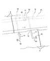
支持具2の取り付けに際しては、先に係止部材18,19を前段の瓦4と後段の瓦6との間に差し込んでおく。
図5(a)に示すように、係止部材18は係止部58を横向きにねかせて差し込む。この係止部58は、横にねかせて差し込めるため、水上側の後段の瓦6を僅かに浮かせて少し隙間を確保する程度で差し込みには十分である。上記係止部材18の係止部58は、前段の瓦4の水上側縁部24を越えた位置まで差し込む。他の係止部材19についても、同様にして係止部58を前段の瓦4と後段の瓦6との間に差し込む。When attaching the
As shown in FIG. 5A, the locking
次に図5(b)に示すように、支持具2の本体3を、上記係止部材18と係止部材19との間に取り付ける。支持具2の本体3は、その台座部材10を屋根斜面に葺かれた前段の瓦4の上面部に載置するとともに、台座部材10を前段の瓦4と後段の瓦6との間に差し込む。これと同時に、押え部材12の押え部38を後段の瓦6の水下側縁部25近傍の上面部に配置する。 Next, as shown in FIG. 5B, the
上記台座部材10を差し込む際には、後段の瓦6の裏溝部70を利用し、この裏溝部70によって形成された隙間に台座部材10を差し込む。なお、上記裏溝部70の無い形状の瓦を後段の瓦に用いる場合には、この瓦と前段の瓦との間の適宜な位置(中央部近傍)に台座部材10を差し込む。この場合、後段の瓦を少し浮かせて隙間を確保する。
上記支持具2の台座部材10及び係止部材18,19は、瓦同士の僅かな隙間に差し込んで配設することが可能であるため、曲面板状、平板状のどのような形状の瓦(葺いた後)にも取り付けることが可能である。When inserting the
Since the
また図5(c)に示すように、上記台座部材10を前段の瓦4と後段の瓦6間に差し込んだ際には、この台座部材10の係止片部32を、後段の瓦6の裏面に形成された係止凸部68に係止させる。なお、上記係止片部32による係止構造により、後段の瓦6に取り付けた支持具2の保持固定が強固になる。
そして、上記台座部材10に対して、その上部に設けられた押え部材12を長孔部44を利用して水上側(或いは水下側)へ移動させ、押え部材12の立上段部40を後段の瓦6の水下側縁部25に当接させる。Further, as shown in FIG. 5C, when the
And the holding
この状態で、支持具2のボルト16に取り付けられたナット17を締付ける。このボルト16締めにより、押え部材12の押え部38が後段の瓦6の上面部を押圧して台座部材10との間で後段の瓦6を挟持し、支持具2自体を後段の瓦6に保持固定する。
これにより支持具2(本体3)は、挟持及び係止の両手段によって後段の瓦6に保持固定される。In this state, the
As a result, the support 2 (main body 3) is held and fixed to the
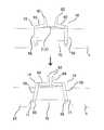
次に図6に示すように、上記前段の瓦4と後段の瓦6間に差し込んだ係止部材18を回して(基体部56を軸にして)係止部58を下向きにし、これを前段の瓦4の水上側縁部24に係止させる。この状態で、係止部材18の締結部62は上向きとなる。
他の係止部材19についても、同様にして基体部56を回して(係止部材18とは逆向き)係止部58を前段の瓦4の水上側縁部24に係止させ、締結部62を上に向ける。Next, as shown in FIG. 6, the locking
Similarly, for the
そして図7に示すように、上記係止部材18,19の各締結部62を、支持具2の本体3の水下側で向い合わせる。このとき、両締結部62は上方に向き且つ左右に開いた状態となる。さらに、ボルト72を上記両締結部62,62の孔部64に挿通し反対側からナット73を締付け、両締結部62,62同士を締結し連結する(図5(c))。 Then, as shown in FIG. 7, the
これにより、係止部材18,19は内向きに少し回って各締結部62は平行に向き合う状態となる。このとき、各係止部58,58はハの字状に開いて各係止部58,58がそれぞれ前段の瓦4の水上側縁部24に係止する。同時に、係止部58,58の係止片66,66が、それぞれ前段の瓦4の水上側縁部24の裏溝部70の両端の角部71,71に係合し、係止部材18,19が固く前段の瓦4に固定される。
なお、上記裏溝部70のない瓦を用いた場合には、係止部58,58の各係止片66,66は、瓦の水上側縁部の裏面部に係合する。Thereby, the locking
When the roof tile without the
また、上記ボルト72、ナット73による両締結部62,62同士の締結(連結)により、係止部材18,19の各基体部56,56は支持具2(本体3)の台座部材10或いは押え部材12の左右の側部を挟持する。この係止部材18,19による挟持により、係止部材18,19が台座部材10(或いは押え部材12)と一体化した状態で支持具2の本体3に固定される。 Further, by fastening (connecting) the
よって上記支持具2は、押え部材12と台座部材10による挟持等により後段の瓦6に固定され、さらに上記係止部材18,19により前段の瓦4にも係止した状態となって移動(水下側への)が阻止される。これにより支持具2は、後段の瓦6と前段の瓦4の両瓦4,6に保持固定されることになり、支持具2の固定が強固になる。
なお、後段の瓦6のみで支持具2の保持固定が十分な場合には、上記係止部材18,19を用いなくても、支持具2の本体3のみを屋根上架台1を支持する支持具として用いることは可能である。Therefore, the
If the
上記支持具2は、屋根上架台1を配置する屋根上に所定の間隔をおいて取り付ける。ここでは、屋根上架台1を形成するレール材74は、屋根上の水上水下方向(縦方向)に配置されることから、支持具2についても上記レール材74に沿った位置に所定の間隔をおいて複数取り付ける。 The
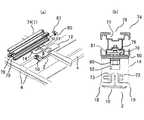
ここで図8(a)(b)に基づき、支持具2に屋根上架台1を取り付ける方法について説明する。
上記屋根上架台1は、複数本のレール材74から構成される。図8(b)に示すように、上記レール材74は断面略矩形状であり、軽合金の押し出し成形により製造されたものである。このレール材74の上部には、上側に開口部76を有する断面C字状の係合溝部77が形成され、また下部には下側に開口部78を有する断面C字状の係合溝部79が形成されている。
そして、上記レール材74を屋根上に複数(縦方向)に配置された支持具2の上部に配置する。Here, based on FIG. 8 (a) (b), the method to attach the
The
And the said
上記レール材74を支持具2に取り付ける際には、ボルト80及び内部ナット81を用いる。この内部ナット81は、螺孔を有する平行四辺形状の板材であり、上記レール材74の係合溝部77内に嵌入可能であり、且つその角部により溝部内での回転は阻止される形状である。
そして、上記ボルト80(及び内部ナット81)を用いてレール材74を支持具2の受部材14に固定する。ここで、受部材14の第一の溝部52は上記ボルト80の頭部が通過可能な大きさに形成され、また第二の溝部53はボルト80の軸部が通過可能(ボルト80の頭部は通過不可)な大きさに形成されている。When the
And the
さて図8(a)に示すように、上記内部ナット81は予めボルト80に螺着しておき、この内部ナット81を上記支持具2の上部に配置したレール材74の係合溝部79に嵌め込む。そして、ボルト80を内部ナット81(係合溝部79内を摺動)とともに移動させ、このボルト80の頭部を受部材14の第一の溝部52を通過させ、さらにボルト80の軸部を第二の溝部53の端部位置まで移動させる。これで、ボルト80の頭部が受部材14の受け部50の下部に位置する。 Now, as shown in FIG. 8A, the
ここで、工具を用いてボルト80を締め付け、支持具2の受部材14にレール材74を固定する。他の支持具2についても、同様にボルト80及び内部ナット81を用いてレール材74を固定する。
また他のレール材74についても、同様にして支持具2に固定する。各レール材74は、水下側端部をそろえて設置する。このように、ボルト80及び内部ナット81を用いることで、支持具2へのレール材74の取り付けが容易に行える。Here, the
The
なお、ここでは屋根上架台1は2本或いは3本以上の縦向きのレール材74からなる形態としているが、他に屋根上架台1として、さらに横向きにもレール材74を配置し、矩形形状にレール材74を配置した屋根上架台の形態を採用することも可能である。この場合には、上記支持具2を縦方向及び横方向の列に沿って配置する。これら支持具2についても、上記ボルト80及び内部ナット81を用いることで容易にレール材74を取り付けることができる。 Here, the
図9に示すように、上記屋根上架台1の上部には、固定金具84を用いて太陽光発電パネル8を取り付ける。太陽光発電パネル8は、偏平な矩形状の形態である。
上記固定金具84は、平坦な固定部86の両側から側壁部88,88が立設形成され、これらの上部からそれぞれ外向きに翼部90,90が形成された断面ハット状の形状である。上記固定部86には、中央部に孔部87が設けられている。また、各翼部90の先部には、内側に折曲した係合部92が形成されている。As shown in FIG. 9, the photovoltaic
The fixing
上記固定金具84は、上記ボルト80及び内部ナット81を用いてレール材74の水下側端部の上部に固定する。まず、固定金具84の固定部86の孔部87にワッシャ93を介してボルト80を挿通し、このボルト80の先に緩く内部ナット81を螺着する。そして、固定金具84をレール材74の端部近傍に配置するとともに、上記内部ナット81をレール材74の係合溝部77に嵌入し、工具を用いてボルト80を締付ける。これにより、レール材74の端部に固定金具84が固定される。他のレール材74についても、同様にして固定金具84を取り付ける。 The fixing
そして図10(a)(b)に示すように、屋根上架台1のレール材74間に太陽光発電パネル8を少し傾斜させて配置し、その水下側の縁部9を上記取り付けた固定金具84の翼部90の係合部92に係合させた状態のまま倒してレール材74の上部に載置する。これにより、太陽光発電パネル8の縁部9が固定金具84によって保持固定される。 And as shown to Fig.10 (a) (b), it arrange | positions the photovoltaic
図11は、支持具2に屋根上架台1および太陽光発電パネル8などを取り付けた状態を示す図である。
このように太陽光発電パネル8の水上側の縁部についても、上記固定金具84を用いてレール材74の上部に固定する。この場合、固定金具84の係合部92を太陽光発電パネル8の水上側縁部に係合させ、この状態でボルト80を締める。FIG. 11 is a diagram illustrating a state where the
In this manner, the water-side edge of the photovoltaic
なお、上記固定金具84は両側に翼部90,90及び係合部92,92が形成されているため、上記太陽光発電パネル8の水上側には、固定金具84の水上側の翼部90及び係合部92を利用して、連続的に他の太陽光発電パネル8の水下側の縁部9を保持固定することができる。
最後に、軒下カバー94、軒下木口フタ95、目地カバー96、目地木口フタ97、レール材の木口フタ98等を取り付ける。Since the fixing
Finally, the eaves
従って、上記実施の形態によれば、屋根瓦に容易かつ迅速に取り付けられて施工性に優れ、また瓦同士の間の隙間に差し込んで保持させ、或いは係止させる形態であり、せいぜい瓦を少し浮かせる程度で済むため、瓦を持ち上げる必要がないため瓦の破損或いは葺いた瓦のずれ等が防止でき、さらには加工が容易で生産性にも優れるという効果がある。 Therefore, according to the above-described embodiment, it is easily and quickly attached to the roof tile, has excellent workability, and is inserted into the gap between the tiles to be held or locked. Since it only needs to be lifted, there is no need to lift the roof tile, so that it is possible to prevent damage to the roof tile or the displacement of the cracked roof tile. Further, the processing is easy and the productivity is excellent.
2 支持具
4 前段の瓦
6 後段の瓦
10 台座部材
12 押え部材
14 受部材
16,17 止着具(ボルト、ナット)
18,19 係止部材
24 水上側縁部
25 水下側縁部
32 係止片部
38 押え部
42 固定部
44 長孔部
46 取付部
50 受け部
56 基体部
58 係止部
60 連結部
68 係止凸部2
18, 19 Locking
Claims (4)
Translated fromJapaneseこの台座部材の上部に固定される固定部、及びこの固定部の水上側に形成され上記後段の瓦の上面部を押える押え部からなる押え部材と、
上記押え部材の固定部の上部に取り付けられる取付部、及びこの取付部の上側に形成され屋根上架台を支持する受け部からなる受部材とを有し、
止着具を用いて上記台座部材、上記押え部材及び上記受部材を一体に締結するとともに、上記後段の瓦を上記台座部材と上記押え部材とで挟持して屋根斜面上に固定し、
上記押え部材の固定部に水上水下向きに長い長孔部を設け、この長孔部に上記止着具を挿通させて、上記台座部材に対する上記押え部材の位置を調節可能としたことを特徴とする屋根上架台の支持具。A pedestal member that is placed on the front tile tiled on the roof slope and partially inserted between the previous tile tile and the rear tile tiled on the water side;
A holding member comprising a fixing part fixed to the upper part of the pedestal member, and a pressing part that is formed on the water side of the fixing part and presses the upper surface part of the rear tile;
A mounting part attached to the upper part of the fixing part of the pressing member, and a receiving member formed on the upper side of the mounting part and comprising a receiving part that supports the roof mount;
The fastening member is used to fasten the pedestal member, the holding member and the receiving member together, and the rear tile is sandwiched between the pedestal member and the holding member and fixed on the roof slope.
The fixing part of the presser member is provided with a long long hole part facing downward in the water, and the fastening member is inserted into the long hole part so that the position of the presser member with respect to the pedestal member can be adjusted. Support for the roof mount.
この台座部材の上部に固定される固定部、及びこの固定部の水上側に形成され上記後段の瓦の上面部を押える押え部からなる押え部材と、
上記押え部材の固定部の上部に取り付けられる取付部、及びこの取付部の上側に形成され屋根上架台を支持する受け部からなる受部材とを有し、
止着具を用いて上記台座部材、上記押え部材及び上記受部材を一体に締結するとともに、上記後段の瓦を上記台座部材と上記押え部材とで挟持して屋根斜面上に固定し、
長尺状の基体部の水上側に横向きに形成される係止部、及び上記基体部の水下側に形成される連結部からなる一対の係止部材を用い、
上記前段の瓦と上記後段の瓦との間に、上記両係止部材の係止部をそれぞれ横向きに倒して差し込み、さらに上記基体部を回して上記係止部を下方に向けるとともに上記前段の瓦の水上側縁部にそれぞれ係止させる一方、上記両係止部材の連結部同士を上記台座部材の水下側で締結するとともに、上記両係止部材をそれぞれ上記台座部材或いは上記押え部材の両側部に保持させたことを特徴とする屋根上架台の支持具。A pedestal member that is placed on the front tile tiled on the roof slope and partially inserted between the previous tile tile and the rear tile tiled on the water side;
A holding member comprising a fixing part fixed to the upper part of the pedestal member, and a pressing part that is formed on the water side of the fixing part and presses the upper surface part of the rear tile;
A mounting part attached to the upper part of the fixing part of the pressing member, and a receiving member formed on the upper side of the mounting part and comprising a receiving part that supports the roof mount;
The fastening member is used to fasten the pedestal member, the holding member and the receiving member together, and the rear tile is sandwiched between the pedestal member and the holding member and fixed on the roof slope.
Using a pair of locking members consisting of a locking part formed laterally on the water side of the elongated base part and a connecting part formed on the water side of the base part,
Between the front roof tile and the rear roof tile, the locking portions of the both locking members are respectively tilted sideways and inserted, and further the base portion is turned to turn the locking portion downward and the front roof tiles. While locking to the water upper edge of the roof tile, the connecting portions of the both locking members are fastened on the underwater side of the pedestal member, and the both locking members are respectively connected to the pedestal member or the holding member. A support for a roof mount, whichis held on both sides .
Priority Applications (1)
| Application Number | Priority Date | Filing Date | Title |
|---|---|---|---|
| JP2011043692AJP5759205B2 (en) | 2011-03-01 | 2011-03-01 | Roof mount support |
Applications Claiming Priority (1)
| Application Number | Priority Date | Filing Date | Title |
|---|---|---|---|
| JP2011043692AJP5759205B2 (en) | 2011-03-01 | 2011-03-01 | Roof mount support |
Publications (2)
| Publication Number | Publication Date |
|---|---|
| JP2012180662A JP2012180662A (en) | 2012-09-20 |
| JP5759205B2true JP5759205B2 (en) | 2015-08-05 |
Family
ID=47012078
Family Applications (1)
| Application Number | Title | Priority Date | Filing Date |
|---|---|---|---|
| JP2011043692AActiveJP5759205B2 (en) | 2011-03-01 | 2011-03-01 | Roof mount support |
Country Status (1)
| Country | Link |
|---|---|
| JP (1) | JP5759205B2 (en) |
Families Citing this family (6)
| Publication number | Priority date | Publication date | Assignee | Title |
|---|---|---|---|---|
| JP6088175B2 (en)* | 2012-08-13 | 2017-03-01 | 日新製鋼株式会社 | Cover member of solar power generation module, installation structure of solar power generation module using the same, and installation method of solar power generation module in building |
| US8806815B1 (en) | 2013-10-15 | 2014-08-19 | Sunmodo Corporation | Adjustable solar panel tile roof mounting device |
| US8839575B1 (en) | 2013-10-15 | 2014-09-23 | Sunmodo Corporation | Adjustable solar panel tile roof mounting device |
| JP6334944B2 (en)* | 2014-02-15 | 2018-05-30 | 奥地建産株式会社 | Support fixing bracket for articles installed on tile roof |
| JP2015158101A (en)* | 2014-02-25 | 2015-09-03 | 株式会社ダイドーハント | On-roof apparatus mounting support device |
| CN106357205B (en)* | 2016-11-01 | 2019-09-13 | 天合光能股份有限公司 | Sloping roof waterproof photovoltaic module installation device |
Family Cites Families (1)
| Publication number | Priority date | Publication date | Assignee | Title |
|---|---|---|---|---|
| JP3322591B2 (en)* | 1997-02-20 | 2002-09-09 | 大同鋼板株式会社 | Mounting brackets for attached structures on horizontal roofs and mounting structures for attached structures on horizontal roofs |
- 2011
- 2011-03-01JPJP2011043692Apatent/JP5759205B2/enactiveActive
Also Published As
| Publication number | Publication date |
|---|---|
| JP2012180662A (en) | 2012-09-20 |
Similar Documents
| Publication | Publication Date | Title |
|---|---|---|
| JP5202430B2 (en) | Solar cell module fixing structure | |
| JP5759205B2 (en) | Roof mount support | |
| US11841038B2 (en) | Panel clamping and mounting mechanism | |
| US9175880B2 (en) | Panel clamping and mounting mechanism | |
| US9175704B2 (en) | Panel clamping and mounting mechanism | |
| US20140130847A1 (en) | PV Array Mounting for Trapezoidal Metal and Low-Slope Roofs | |
| US20120167364A1 (en) | Apparatus for fastening a mounting rail to a threaded shaft | |
| JP5588227B2 (en) | Mounting device for installation on the roof | |
| JP2011236611A (en) | Method and structure for installing solar cell module | |
| JP2011054690A (en) | Solar power generator | |
| WO2024092995A1 (en) | Photovoltaic bracket hook | |
| JP3173601U (en) | Support bracket for solar cell panel support structure and solar cell panel support structure using the support bracket | |
| JP5469442B2 (en) | Solar panel installation equipment on the roof, and installation method for installing the solar panel on the roof | |
| JP3869292B2 (en) | Support bracket for solar panel mounting | |
| JP2012017569A (en) | Fixing component of outdoor structure | |
| JP2011256636A (en) | Foundation device for solar panel installation | |
| JP3160551U (en) | Roof mount system | |
| JP2015055042A (en) | Installation member for equipment and equipment installation roof | |
| JP5488586B2 (en) | Solar panel peripheral structure | |
| JP5588741B2 (en) | Mounting device for installation on the roof | |
| JP5660550B2 (en) | External member mounting structure and mounting method | |
| JP5675913B1 (en) | Solar panel mounting bracket for metal roof | |
| JP2012021340A (en) | Solar panel-mounting unit | |
| JP7624714B2 (en) | Mounting member for external components, installation method of external components using the same, adjustment method of the installation direction of external components, and installation structure | |
| JP4878402B1 (en) | Piping fixing base |
Legal Events
| Date | Code | Title | Description |
|---|---|---|---|
| A621 | Written request for application examination | Free format text:JAPANESE INTERMEDIATE CODE: A621 Effective date:20140117 | |
| A977 | Report on retrieval | Free format text:JAPANESE INTERMEDIATE CODE: A971007 Effective date:20141028 | |
| A131 | Notification of reasons for refusal | Free format text:JAPANESE INTERMEDIATE CODE: A131 Effective date:20141111 | |
| A521 | Request for written amendment filed | Free format text:JAPANESE INTERMEDIATE CODE: A523 Effective date:20141216 | |
| TRDD | Decision of grant or rejection written | ||
| A01 | Written decision to grant a patent or to grant a registration (utility model) | Free format text:JAPANESE INTERMEDIATE CODE: A01 Effective date:20150602 | |
| A61 | First payment of annual fees (during grant procedure) | Free format text:JAPANESE INTERMEDIATE CODE: A61 Effective date:20150605 | |
| R150 | Certificate of patent or registration of utility model | Ref document number:5759205 Country of ref document:JP Free format text:JAPANESE INTERMEDIATE CODE: R150 | |
| R250 | Receipt of annual fees | Free format text:JAPANESE INTERMEDIATE CODE: R250 | |
| R250 | Receipt of annual fees | Free format text:JAPANESE INTERMEDIATE CODE: R250 | |
| R250 | Receipt of annual fees | Free format text:JAPANESE INTERMEDIATE CODE: R250 | |
| R250 | Receipt of annual fees | Free format text:JAPANESE INTERMEDIATE CODE: R250 | |
| R250 | Receipt of annual fees | Free format text:JAPANESE INTERMEDIATE CODE: R250 | |
| R250 | Receipt of annual fees | Free format text:JAPANESE INTERMEDIATE CODE: R250 | |
| R250 | Receipt of annual fees | Free format text:JAPANESE INTERMEDIATE CODE: R250 | |
| R250 | Receipt of annual fees | Free format text:JAPANESE INTERMEDIATE CODE: R250 |