JP5759183B2 - Optical connector and assembly method thereof - Google Patents
Optical connector and assembly method thereofDownload PDFInfo
- Publication number
- JP5759183B2 JP5759183B2JP2011005999AJP2011005999AJP5759183B2JP 5759183 B2JP5759183 B2JP 5759183B2JP 2011005999 AJP2011005999 AJP 2011005999AJP 2011005999 AJP2011005999 AJP 2011005999AJP 5759183 B2JP5759183 B2JP 5759183B2
- Authority
- JP
- Japan
- Prior art keywords
- housing
- optical fiber
- optical
- fusion
- optical connector
- Prior art date
- Legal status (The legal status is an assumption and is not a legal conclusion. Google has not performed a legal analysis and makes no representation as to the accuracy of the status listed.)
- Active
Links
Images


Classifications
- G—PHYSICS
- G02—OPTICS
- G02B—OPTICAL ELEMENTS, SYSTEMS OR APPARATUS
- G02B6/00—Light guides; Structural details of arrangements comprising light guides and other optical elements, e.g. couplings
- G02B6/24—Coupling light guides
- G02B6/36—Mechanical coupling means
- G02B6/38—Mechanical coupling means having fibre to fibre mating means
- G02B6/3807—Dismountable connectors, i.e. comprising plugs
- G02B6/3833—Details of mounting fibres in ferrules; Assembly methods; Manufacture
- G02B6/3846—Details of mounting fibres in ferrules; Assembly methods; Manufacture with fibre stubs
- G—PHYSICS
- G02—OPTICS
- G02B—OPTICAL ELEMENTS, SYSTEMS OR APPARATUS
- G02B6/00—Light guides; Structural details of arrangements comprising light guides and other optical elements, e.g. couplings
- G02B6/24—Coupling light guides
- G02B6/255—Splicing of light guides, e.g. by fusion or bonding
- G—PHYSICS
- G02—OPTICS
- G02B—OPTICAL ELEMENTS, SYSTEMS OR APPARATUS
- G02B6/00—Light guides; Structural details of arrangements comprising light guides and other optical elements, e.g. couplings
- G02B6/24—Coupling light guides
- G02B6/36—Mechanical coupling means
- G02B6/38—Mechanical coupling means having fibre to fibre mating means
- G02B6/3807—Dismountable connectors, i.e. comprising plugs
- G02B6/3887—Anchoring optical cables to connector housings, e.g. strain relief features
- G—PHYSICS
- G02—OPTICS
- G02B—OPTICAL ELEMENTS, SYSTEMS OR APPARATUS
- G02B6/00—Light guides; Structural details of arrangements comprising light guides and other optical elements, e.g. couplings
- G02B6/24—Coupling light guides
- G02B6/255—Splicing of light guides, e.g. by fusion or bonding
- G02B6/2558—Reinforcement of splice joint
- G—PHYSICS
- G02—OPTICS
- G02B—OPTICAL ELEMENTS, SYSTEMS OR APPARATUS
- G02B6/00—Light guides; Structural details of arrangements comprising light guides and other optical elements, e.g. couplings
- G02B6/24—Coupling light guides
- G02B6/36—Mechanical coupling means
- G02B6/38—Mechanical coupling means having fibre to fibre mating means
- G02B6/3807—Dismountable connectors, i.e. comprising plugs
- G02B6/3873—Connectors using guide surfaces for aligning ferrule ends, e.g. tubes, sleeves, V-grooves, rods, pins, balls
- G02B6/3885—Multicore or multichannel optical connectors, i.e. one single ferrule containing more than one fibre, e.g. ribbon type
- G—PHYSICS
- G02—OPTICS
- G02B—OPTICAL ELEMENTS, SYSTEMS OR APPARATUS
- G02B6/00—Light guides; Structural details of arrangements comprising light guides and other optical elements, e.g. couplings
- G02B6/24—Coupling light guides
- G02B6/36—Mechanical coupling means
- G02B6/38—Mechanical coupling means having fibre to fibre mating means
- G02B6/3807—Dismountable connectors, i.e. comprising plugs
- G02B6/3887—Anchoring optical cables to connector housings, e.g. strain relief features
- G02B6/38875—Protection from bending or twisting
- Y—GENERAL TAGGING OF NEW TECHNOLOGICAL DEVELOPMENTS; GENERAL TAGGING OF CROSS-SECTIONAL TECHNOLOGIES SPANNING OVER SEVERAL SECTIONS OF THE IPC; TECHNICAL SUBJECTS COVERED BY FORMER USPC CROSS-REFERENCE ART COLLECTIONS [XRACs] AND DIGESTS
- Y10—TECHNICAL SUBJECTS COVERED BY FORMER USPC
- Y10T—TECHNICAL SUBJECTS COVERED BY FORMER US CLASSIFICATION
- Y10T29/00—Metal working
- Y10T29/49—Method of mechanical manufacture
- Y10T29/49826—Assembling or joining
Landscapes
- Physics & Mathematics (AREA)
- General Physics & Mathematics (AREA)
- Optics & Photonics (AREA)
- Engineering & Computer Science (AREA)
- Plasma & Fusion (AREA)
- Mechanical Coupling Of Light Guides (AREA)
Description
Translated fromJapanese本発明は、光ファイバテープ心線が内蔵された光ファイバコードが組み付けられる光コネクタ及びその組立方法に関するものである。 The present invention relates to an optical connector to which an optical fiber cord incorporating an optical fiber ribbon is assembled and an assembling method thereof.
従来の光コネクタとしては、例えば特許文献1に記載されているものが知られている。特許文献1に記載の光コネクタは、フェルールに内挿固定された内蔵光ファイバと光ファイバコード端末に露出した光ファイバテープ心線との融着接続部を補強スリーブで補強してなる接続補強部を、フェルールと共にハウジング内に設けた構造を有している。 As a conventional optical connector, for example, one described in Patent Document 1 is known. The optical connector described in Patent Document 1 is a connection reinforcing portion formed by reinforcing a fusion connecting portion between a built-in optical fiber inserted and fixed in a ferrule and an optical fiber tape core wire exposed at an optical fiber cord end with a reinforcing sleeve. Is provided in the housing together with the ferrule.
しかしながら、上記従来技術においては、以下の問題点が存在する。即ち、上記従来技術では、光ファイバコードの外被を光コネクタに固定していないため、光ファイバコードを強く引っ張ると、光ファイバコードが光コネクタから外れてしまうことがある。仮に光ファイバコードの外被を固定するための構造を設けると、その分だけ光コネクタの寸法が増大するため、複数の光ファイバコード付き光コネクタを高密度に配置することが困難になる。 However, the following problems exist in the prior art. That is, in the above prior art, since the jacket of the optical fiber cord is not fixed to the optical connector, if the optical fiber cord is pulled strongly, the optical fiber cord may come off from the optical connector. If a structure for fixing the jacket of the optical fiber cord is provided, the size of the optical connector increases correspondingly, and it becomes difficult to arrange a plurality of optical connectors with optical fiber cords at high density.
また、上記従来技術では、補強スリーブに棒状の補強心材が埋め込まれているが、1本の棒状の補強心材だけでは、補強スリーブを加熱収縮したときに補強スリーブが曲がってしまう可能性がある。このとき、複数本の棒状の補強心材を補強スリーブに埋め込むと、補強スリーブの寸法が増大してしまう。 Further, in the above-described prior art, a rod-shaped reinforcing core material is embedded in the reinforcing sleeve. However, with only one rod-shaped reinforcing core material, the reinforcing sleeve may be bent when the reinforcing sleeve is heated and contracted. At this time, if a plurality of rod-shaped reinforcing cores are embedded in the reinforcing sleeve, the size of the reinforcing sleeve increases.
さらに、上記従来技術において、ガイドピンを有する雄型の光コネクタでは、フェルール本体の後部にガイドピンの抜け止め用のピンクランプが設けられており、ピンクランプのガイドピンをフェルール本体のガイドピン穴に貫通させるようにしている。一方、ガイドピンを有しない雌型の光コネクタについては、本来ならばピンクランプは不要であるが、雄型の光コネクタの動作特性と合わせるために、ピンクランプに相当するスペーサを設けている場合がある。しかし、そのようなスペーサは微小部品であるため、フェルール本体とスペーサとの位置合わせが困難であり、光コネクタの組み立ての作業性が低下する。 Further, in the above-described prior art, in the male optical connector having a guide pin, a pin clamp for preventing the guide pin from coming off is provided at the rear part of the ferrule body, and the guide pin hole of the ferrule body is connected to the pin pin of the pin clamp. To penetrate. On the other hand, for female optical connectors that do not have guide pins, pin clamps are not necessary, but spacers corresponding to pin clamps are provided to match the operating characteristics of male optical connectors. There is. However, since such a spacer is a minute part, it is difficult to align the ferrule body and the spacer, and the workability of assembling the optical connector is reduced.
本発明の目的は、コネクタ寸法を大きくすること無く、光ファイバコードの外被を固定することができる光コネクタ及びその組立方法を提供することである。 An object of the present invention is to provide an optical connector capable of fixing an outer jacket of an optical fiber cord and an assembling method thereof without increasing the connector size.
本発明は、複数本の光ファイバを有する光ファイバテープ心線が内蔵された光ファイバコードが組み付けられる光コネクタにおいて、各光ファイバと融着接続される複数本の内蔵ファイバを保持したフェルール部材と、各光ファイバと各内蔵ファイバとの融着接続部を保護するための融着保護スリーブをフェルール部材と共に収容するハウジングと、ハウジングの後側部分に装着され、光ファイバコードの外被をハウジングに挟み込んで固定する固定部材とを備え、ハウジングの後端部には、引き裂かれた状態の外被を載せるための凹みが設けられており、ハウジングの後端部は、断面略長円形状を有し、凹みは、ハウジングの後端部におけるハウジングの長径方向に沿った部位にハウジングの短径方向に対向するように設けられていることを特徴とするものである。The present invention relates to an optical connector for assembling an optical fiber cord in which an optical fiber ribbon having a plurality of optical fibers is incorporated, and a ferrule member holding a plurality of built-in fibers that are fusion-bonded to the respective optical fibers; A housing for housing a fusion protection sleeve for protecting the fusion spliced portion between each optical fiber and each built-in fiber together with a ferrule member; and a housing attached to a rear portion of the housing, and covering the optical fiber cord with the housing And a recess for placing a torn outer cover onthe rear end of the housing. The rear end of the housing has a substantially oval cross section. and, indentations, that areprovided so as to face the short diameter direction of the housing portion along the major axis direction of the housing at the rear end portion of the housing It is an feature.
このような本発明の光コネクタに光ファイバコードを組み付ける場合は、光ファイバコードの外被を引き裂いて光ファイバテープ心線を露出させると共に、融着保護スリーブを光ファイバコードに取り付けておく。そして、光ファイバテープ心線の各光ファイバとフェルール部材に保持された各内蔵ファイバとを融着接続し、各光ファイバと各内蔵ファイバとの融着接続部を融着保護スリーブで保護する。そして、融着保護スリーブ及びフェルール部材をハウジング内に収容し、引き裂かれた状態の外被をハウジングの凹みに載せ、その状態で固定部材をハウジングの後側部分に装着することで、固定部材により外被をハウジングに挟み込んで固定する。このようにハウジングの後端部に凹みを設け、引き裂かれた状態の外被を凹みに入れることにより、固定部材の外径を大きくしなくて済む。これにより、光コネクタの寸法を大きくすること無く、光ファイバコードの外被を容易に且つ確実に光コネクタに固定することができる。 When the optical fiber cord is assembled to such an optical connector of the present invention, the outer sheath of the optical fiber cord is torn to expose the optical fiber tape core wire, and the fusion protection sleeve is attached to the optical fiber cord. Then, each optical fiber of the optical fiber ribbon and each built-in fiber held by the ferrule member are fusion-bonded, and a fusion-bonded portion between each optical fiber and each built-in fiber is protected by a fusion protection sleeve. Then, the fusion protection sleeve and the ferrule member are accommodated in the housing, the torn outer cover is placed on the recess of the housing, and the fixing member is attached to the rear side portion of the housing in that state, so that the fixing member The outer cover is sandwiched between the housings and fixed. Thus, by providing a recess at the rear end of the housing and putting the torn outer cover into the recess, the outer diameter of the fixing member does not have to be increased. As a result, the jacket of the optical fiber cord can be easily and reliably fixed to the optical connector without increasing the size of the optical connector.
好ましくは、融着保護スリーブには、融着保護スリーブの長手方向に延びる補強用の金属板が設けられている。 Preferably, the fusion protection sleeve is provided with a reinforcing metal plate extending in the longitudinal direction of the fusion protection sleeve.
このように融着保護スリーブに補強用の金属板を設けることにより、融着保護スリーブを加熱収縮した際に発生する融着保護スリーブの曲がりを十分に抑制することができる。また、例えばガラス系セラミックを融着保護スリーブの補強材として用いる場合には、補強材の強度を確保するために補強材を十分厚くする必要があるが、金属板を補強材として使用することにより、補強材を必要以上に厚くしなくても、補強材の強度が確保される。これにより、融着保護スリーブの寸法を大きくしなくて済む。 By providing a reinforcing metal plate on the fusion protection sleeve in this way, it is possible to sufficiently suppress the bending of the fusion protection sleeve that occurs when the fusion protection sleeve is heated and shrunk. For example, when glass-based ceramic is used as a reinforcing material for a fusion protection sleeve, it is necessary to make the reinforcing material sufficiently thick in order to ensure the strength of the reinforcing material, but by using a metal plate as a reinforcing material. Even if the reinforcing material is not thickened more than necessary, the strength of the reinforcing material is ensured. This eliminates the need for increasing the size of the fusion protection sleeve.
また、好ましくは、フェルール部材は、ガイドピンが挿入される1対のガイド孔を有するフェルール本体と、フェルール本体の後側に配置され、各ガイド孔に挿入される1対の突起を有するスペーサとを有する。 Preferably, the ferrule member includes a ferrule body having a pair of guide holes into which guide pins are inserted, and a spacer having a pair of protrusions disposed on the rear side of the ferrule body and inserted into each guide hole. Have
このようにスペーサに1対の突起を設けることにより、フェルール本体の各ガイド孔に1対の突起を挿入するだけで、フェルール本体とスペーサとの位置合わせを容易に行うことができる。その結果、光コネクタの組み立ての作業性を向上させることができる。 By providing a pair of protrusions on the spacer in this way, the ferrule body and the spacer can be easily aligned by simply inserting a pair of protrusions into each guide hole of the ferrule body. As a result, the workability of assembling the optical connector can be improved.
本発明の光コネクタの組立方法は、上記の光コネクタを用意する工程と、光ファイバコードの外被を引き裂いて光ファイバテープ心線を露出させると共に、融着保護スリーブを光ファイバコードに取り付ける工程と、光ファイバテープ心線の各光ファイバとフェルール部材に保持された各内蔵ファイバとを融着接続し、各光ファイバと各内蔵ファイバとの融着接続部を融着保護スリーブで保護する工程と、フェルール部材及び融着保護スリーブをハウジング内に収容し、引き裂かれた状態の外被をハウジングの凹みに載せ、その状態で固定部材をハウジングの後側部分に装着することで、固定部材により外被をハウジングに挟み込んで固定する工程とを含むことを特徴とするものである。 The optical connector assembling method of the present invention includes the steps of preparing the above optical connector, tearing the jacket of the optical fiber cord to expose the optical fiber ribbon, and attaching the fusion protection sleeve to the optical fiber cord. And fusion-connecting each optical fiber of the optical fiber ribbon and each built-in fiber held by the ferrule member, and protecting the fusion-bonded portion between each optical fiber and each built-in fiber with a fusion protection sleeve The ferrule member and the fusion protection sleeve are accommodated in the housing, the torn outer cover is placed on the recess of the housing, and the fixing member is attached to the rear portion of the housing in this state, And a step of sandwiching and fixing the outer cover in the housing.
このように本発明の光コネクタの組立方法においては、上述したように、光コネクタの寸法を大きくすること無く、光ファイバコードの外被を容易に且つ確実に光コネクタに固定することができる。 Thus, in the optical connector assembling method of the present invention, as described above, the jacket of the optical fiber cord can be easily and reliably fixed to the optical connector without increasing the size of the optical connector.
本発明によれば、光コネクタの寸法を大きくすること無く、光ファイバコードの外被を光コネクタに固定することができる。これにより、複数の光ファイバコード付き光コネクタを高密度に配置することが可能となる。 According to the present invention, the jacket of the optical fiber cord can be fixed to the optical connector without increasing the size of the optical connector. Thereby, a plurality of optical connectors with optical fiber cords can be arranged with high density.
以下、本発明に係わる光コネクタ及びその組立方法の好適な実施形態について、図面を参照して詳細に説明する。 Preferred embodiments of an optical connector and its assembling method according to the present invention will be described below in detail with reference to the drawings.
図1は、本発明に係わる光コネクタの一実施形態に光ファイバコードが組み付けられた状態(光ファイバコード付き光コネクタ)の外観を示す斜視図である。図1(a)に示す光コネクタ1Aは、雄型のMPOコネクタであり、図1(b)に示す光コネクタ1Bは、雌型のMPOコネクタである。光コネクタ1A,1B同士は、光アダプタ(図示せず)を介してコネクタ接続される。 FIG. 1 is a perspective view showing an appearance of an optical fiber cord assembled to an embodiment of an optical connector according to the present invention (an optical connector with an optical fiber cord). An
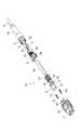
図2は、図1(a)に示した光ファイバコード付き光コネクタの分解斜視図であり、図3は、図1(a)に示した光ファイバコード付き光コネクタの断面図である。なお、図3(b)は、図3(a)のB−B線断面図である。 2 is an exploded perspective view of the optical connector with the optical fiber cord shown in FIG. 1A, and FIG. 3 is a cross-sectional view of the optical connector with the optical fiber cord shown in FIG. FIG. 3B is a cross-sectional view taken along the line BB in FIG.
各図において、光コネクタ1Aに組み付けられる光ファイバコード2は、複数本の光ファイバ3aが配列されてなる光ファイバテープ心線3と、この光ファイバテープ心線3を被覆する外被4と、光ファイバテープ心線3と外被4との間に介在された複数本の抗張力繊維(アラミド繊維)5とを有している。 In each figure, an
光コネクタ1Aは、フェルール部材6と、フロントハウジング7と、リアハウジング8と、固定部材9と、ブーツ10とを備えている。 The optical connector 1 </ b> A includes a
フェルール部材6は、MT型のフェルール本体11と、このフェルール本体11の後側に配置されるピンキーパー12とからなっている。フェルール本体11は、1対のガイド孔13(図1(b)等参照)と、各ガイド孔13間に配置された複数のファイバ孔とを有している。各ファイバ孔には、光ファイバテープ心線3の各光ファイバ3aと融着接続される複数本の短尺状の内蔵ファイバ14が挿入されている。ピンキーパー12は、各ガイド孔13を貫通する1対のガイドピン15を有している。 The
フロントハウジング7は、フェルール部材6と融着保護スリーブ16の一部とを収容する部材である。融着保護スリーブ16は、フェルール本体6に保持された各内蔵ファイバ14と光ファイバテープ心線3の各光ファイバ3aとの融着接続部Sを補強するものである。融着保護スリーブ16の長さは、例えば27mm程度である。 The
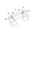
融着保護スリーブ16は、図4に示すように、断面楕円状の熱収縮チューブ17と、この熱収縮チューブ17内に配置された断面楕円状の熱溶融性樹脂チューブ18とを有している。熱収縮チューブ17と熱溶融性樹脂チューブ18との間には、融着保護スリーブ16の長手方向に延びる補強用の金属板19が介在されている。金属板19は、例えばSUS304等で形成された薄型平板である。金属板19の寸法は、例えば厚み0.2〜0.3mm×幅3.7mm×長さ26mm程度である。 As shown in FIG. 4, the
フロントハウジング7には、光アダプタ(図示せず)から光コネクタ1Aを引き抜くためのカップリング20がフロントハウジング7の前後方向に移動可能に取り付けられている。フロントハウジング7の両側面には、図5に示すように、バネ収容溝21が形成されている。バネ収容溝21には、カップリング20をフロントハウジング7に対して前側に付勢するためのイジェクタバネ22が配置されている。また、フロントハウジング7の後部には、2つの係止窓23が上下に形成されている。 A
フロントハウジング7には、リアハウジング8が連結される。リアハウジング8は、フロントハウジング7と協働して融着保護スリーブ16を収容する部材である。リアハウジング8の上面及び下面の前部には、図6に示すように、フロントハウジング7の各係止窓23と係合する係止突起24がそれぞれ設けられている。 A
また、リアハウジング8の後端側部分は、断面略長円形状をなしている。リアハウジング8の後端部における各係止突起24の配置部位(上面及び下面)に対応する部位には、光ファイバコード2の外被4における引き裂かれた部分(図2参照)を載せるための凹み25がそれぞれ形成されている。このとき、外被4は、二股に引き裂かれた状態で各凹み25に載せられる。凹み25は、リアハウジング8における凹み25の部分の肉厚が全体的に均一になるように切削加工されているのが望ましい。また、リアハウジング8における係止突起24と凹み25との間の領域の外周面には、雄ネジ部26が形成されている。 In addition, the rear end portion of the
フェルール部材6とリアハウジング8との間には、フェルール部材6をフロントハウジング7に対して前側に付勢するためのフェルールバネ27が配置されている。 A
リアハウジング8には、固定部材9がネジ止めされる。固定部材9は、光ファイバコード2の外被4及び抗張力繊維5をリアハウジング8に挟み込んで固定する円筒状の部材である。固定部材9の前側部分の内周面には、リアハウジング8の雄ネジ部26と螺合する雌ネジ部28が形成されている。 A fixing
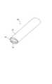
固定部材9の後側部分には、ブーツ10が装着されている。ブーツ10は、光ファイバコード2に急激な曲げが作用しないように光ファイバコード2を保護するものである。ブーツ10には、補強チューブ29が予め取り付けられている。 A
固定部材9により光ファイバコード2の外被4及び抗張力繊維5をリアハウジング8に固定するときは、図7(a)に示すように、まず光ファイバコード2の先端部分の外被4を二股となるように引き裂く。そして、図7(b)に示すように、二股状態の外被4をリアハウジング8の各凹み25に載せる。 When the
続いて、光ファイバコード2の抗張力繊維5(不図示)を二股状態の外被4の隙間から引き出し、リアハウジング8の雄ネジ部26上に載せた状態で、図7(c)に示すように、リアハウジング8に固定部材9をねじ込む。これにより、外被4及び抗張力繊維5がリアハウジング8と固定部材9とに挟み込まれて固定されることとなる。 Subsequently, the tensile strength fiber 5 (not shown) of the
次に、以上のように構成した光コネクタ1に光ファイバコード2を組み付ける光コネクタ組立方法について説明する。まず光ファイバコード2の先端部分の外被4を除去して、光ファイバテープ心線3及び抗張力繊維5を露出させる。続いて、外被4の先端部分を引き裂いて二股状態とする。 Next, an optical connector assembling method for assembling the
続いて、融着保護スリーブ16に光ファイバコード2を通すことで、融着保護スリーブ16を予め光ファイバコード2に取り付けておく。続いて、光ファイバテープ心線3の被覆を除去して各光ファイバ3aを露出させ、その各光ファイバ3aの先端部をカットする。 Subsequently, the
続いて、フェルール部材6に保持された各内蔵ファイバ14と光ファイバテープ心線3の各光ファイバ3aとを融着接続機(図示せず)によって融着接続する。このとき、フェルール本体11に紐付きダストキャップ(図示せず)を被せた状態で、内蔵ファイバ14と光ファイバ3aとの融着接続を行うのが望ましい。 Subsequently, each built-in
続いて、内蔵ファイバ14と光ファイバ3aとの融着接続部Sの位置が融着保護スリーブ16の長手方向の中央部になるように融着保護スリーブ16を移動させ、その状態で融着保護スリーブ16を加熱収縮する。このとき、融着保護スリーブ16内には金属板19が入っているので、融着接続部Sが融着保護スリーブ16により十分に保護されることとなる。 Subsequently, the
続いて、光ファイバコード2が接続された状態のフェルール部材6をフロントハウジング7に組み込む。続いて、リアハウジング8とブーツ10が付いた固定部材9とに融着保護スリーブ16を通した状態で、フロントハウジング7にリアハウジング8を取り付ける。そして、図7に示すように、固定部材9をリアハウジング8に装着することで、光ファイバコード2の外被4及び抗張力繊維5をリアハウジング8及び固定部材9により固定する。以上により、図1(a)に示すような光ファイバコード2付きの光コネクタ1Aが完成する。 Subsequently, the
なお、上記のように光ファイバコード2の外被4及び抗張力繊維5をリアハウジング8及び固定部材9により固定することで、外被4を必ずしも強固に固定できない場合でも、フェルール部材6に対して外被4(光ファイバコード2)が長手方向に沿った軸回りに回転してしまうことを防止できる。 Even if the
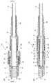
図8は、図1(b)に示した光ファイバコード付き光コネクタの分解斜視図であり、図9は、図1(b)に示した光ファイバコード付き光コネクタの断面図である。なお、図9(b)は、図9(a)のB−B線断面図である。 8 is an exploded perspective view of the optical connector with the optical fiber cord shown in FIG. 1B, and FIG. 9 is a cross-sectional view of the optical connector with the optical fiber cord shown in FIG. FIG. 9B is a cross-sectional view taken along line BB in FIG.
各図において、光コネクタ1Bは、フェルール部材30と、フロントハウジング7と、リアハウジング8と、固定部材9と、ブーツ10とを備えている。フェルール部材30は、上記のフェルール本体11と、このフェルール本体11の後側に配置されるスペーサ31とからなっている。 In each figure, the
スペーサ31は、図10に示すように、フェルール本体11の各ガイド孔13に挿入される1対のピン状突起32を有している。ピン状突起32は、外側に僅かに突出した4つの突出部32aが等間隔で設けられた断面略円形状をなしている。また、ピン状突起32は、根元側部分が先端側部分よりも太くなるように形成されている。具体的には、ピン状突起32は、根元から先端側に向かって0.5度程度の傾斜がつけられている。 As shown in FIG. 10, the
光コネクタ1Bのその他の構成、光コネクタ1Bに光ファイバコード2を組み付ける手順については、上述した光コネクタ1Aと同様である。 Other configurations of the
以上のように本実施形態にあっては、リアハウジング8の後端部に、光ファイバコード2における二股に引き裂さかれた状態の外被4を載せるための2つの凹み25を形成し、これらの凹み25に二股状態の外被4を位置決め収容した状態で、リアハウジング8に固定部材9をねじ込んで装着するようにしたので、固定部材9の外径寸法を増大させること無しに、現地において外被4を容易に且つ確実に固定することができる。これにより、例えば複数の光ファイバコード2付きの光コネクタ1A,1Bを所定のスペースに並べて配置する場合に、これらの光コネクタ1A,1Bを上下方向に高密度に配置することが可能となる。 As described above, in the present embodiment, two
なお、外被4を載せるためにリアハウジング8に設けられた凹み25は、特に2つでなくても良いが、断面略長円形状を有するリアハウジング8の後端部における少なくとも長径方向の部位(図6の上面及び下面に対応する部位)にあることが好ましい。 Note that the number of the
また、融着保護スリーブ16に金属板19を設けたので、融着保護スリーブ16が加熱収縮された後は、融着接続部Sが融着保護スリーブ16により保護される。ここで、金属板19の代わりにガラス系セラミック板を使用することが考えられるが、強度確保のためにはガラス系セラミック板を厚くせざるを得ず、融着保護スリーブ16の寸法の増大につながり、その結果ハウジングサイズも増大する。 In addition, since the
本実施形態では、ガラス系セラミック板ではなく金属板19を使用することにより、金属板19を多少薄くしても強度が確保されるため、融着保護スリーブ16、ひいては光コネクタ1A,1B全体の寸法の増大を抑えることができる。なお、このような融着保護スリーブ16は、コード型だけでなく、リボン(テープ)ファイバのみを用いるもの等、他の多心コネクタにも適用可能である。 In the present embodiment, since the
ところで、雌型の光コネクタ1Bにはガイドピンが無いため、上記のピンキーパー12は不要である。しかし、上記のフェルールバネ27は、フェルール部材とリアハウジング8との間で位置合わせされる。このため、ピンキーパー12の有無によってフェルール部材とリアハウジング8との間隔が変わるため、フェルールバネ27によりフェルール本体11に加わる押圧力が雄型の光コネクタ1Aと雌型の光コネクタ1Bとで異なってしまう。 By the way, since the female
従って、雌型の光コネクタ1Bには、フェルールバネ27による押圧力調整用の部品としてのスペーサ31が具備されている。このとき、スペーサ31には1対のピン状突起32が設けられているので、フェルール本体11のガイド孔13にピン状突起32を差し込むことで、フェルール本体11に対するスペーサ31の位置合わせを容易に行うことができる。その結果、現地における光コネクタ1A,1Bの組立作業性を向上させることが可能となる。なお、このようなスペーサ31の構造は、リボン(テープ)ファイバのみを用いるもの等、他の多心コネクタにも適用可能である。 Accordingly, the female
なお、本発明は、上記実施形態に限定されるものではない。例えば、上記実施形態では、リアハウジング8の外周面に雄ネジ部26が形成され、固定部材9の内周面に雌ネジ部28が形成されているが、リアハウジング8と固定部材9とで雄雌のネジ部が逆に付いていても良い。また、リアハウジング8への固定部材9の装着手段としては、特にネジ止めでなくても良い。 The present invention is not limited to the above embodiment. For example, in the above embodiment, the
また、上記実施形態の光コネクタ1A,1Bは、現地付け型のMPOコネクタであるが、本発明は、工場付け型のMPOコネクタや他の多心コネクタや単心コネクタ等にも適用可能である。 The
1A,1B…光コネクタ、2…光ファイバコード、3…光ファイバテープ心線、3a…光ファイバ、4…外被、6…フェルール部材、7…フロントハウジング、8…リアハウジング、9…固定部材、11…フェルール本体、13…ガイド孔、14…内蔵ファイバ、15…ガイドピン、16…融着保護スリーブ、19…金属板、25…凹み、30…フェルール部材、31…スペーサ、32…ピン状突起、S…融着接続部。 DESCRIPTION OF
Claims (4)
Translated fromJapanese前記各光ファイバと融着接続される複数本の内蔵ファイバを保持したフェルール部材と、
前記各光ファイバと前記各内蔵ファイバとの融着接続部を保護するための融着保護スリーブを前記フェルール部材と共に収容するハウジングと、
前記ハウジングの後側部分に装着され、前記光ファイバコードの外被を前記ハウジングに挟み込んで固定する固定部材とを備え、
前記ハウジングの後端部には、引き裂かれた状態の前記外被を載せるための凹みが設けられており、
前記ハウジングの後端部は、断面略長円形状を有し、
前記凹みは、前記ハウジングの後端部における前記ハウジングの長径方向に沿った部位に前記ハウジングの短径方向に対向するように設けられていることを特徴とする光コネクタ。In an optical connector in which an optical fiber cord with a built-in optical fiber ribbon having a plurality of optical fibers is assembled,
A ferrule member holding a plurality of built-in fibers that are fusion-spliced with the optical fibers;
A housing for housing a fusion protection sleeve for protecting the fusion spliced portion between each optical fiber and each built-in fiber together with the ferrule member;
A fixing member mounted on a rear portion of the housing, and sandwiching and fixing the outer sheath of the optical fiber cord between the housing,
The rear end of the housing is provided with a recess for placing the outer jacket in a torn state,
The rear end of the housing has a substantially oval cross section,
The optical connectoraccording to claim 1, wherein the recess is provided at a rear end portion of the housing along a major axis direction of the housing so as to face the minor axis direction of the housing .
前記光ファイバコードの前記外被を引き裂いて前記光ファイバテープ心線を露出させると共に、前記融着保護スリーブを前記光ファイバコードに取り付ける工程と、
前記光ファイバテープ心線の前記各光ファイバと前記フェルール部材に保持された前記各内蔵ファイバとを融着接続し、前記各光ファイバと前記各内蔵ファイバとの融着接続部を前記融着保護スリーブで保護する工程と、
前記フェルール部材及び前記融着保護スリーブを前記ハウジング内に収容し、前記引き裂かれた状態の外被を前記ハウジングの前記凹みに載せ、その状態で前記固定部材を前記ハウジングの後側部分に装着することで、前記固定部材により前記外被を前記ハウジングに挟み込んで固定する工程とを含むことを特徴とする光コネクタの組立方法。Preparing the optical connector according to any one of claims 1 to 3,
Tearing the jacket of the optical fiber cord to expose the optical fiber ribbon and attaching the fusion protection sleeve to the optical fiber cord;
The optical fibers of the optical fiber ribbon and the built-in fibers held by the ferrule member are fusion-bonded, and the fusion-bonded portion between the optical fibers and the built-in fibers is protected by fusion. A process of protecting with a sleeve;
The ferrule member and the fusion protection sleeve are accommodated in the housing, the torn outer cover is placed in the recess of the housing, and the fixing member is mounted on the rear portion of the housing in that state. And a step of sandwiching and fixing the outer cover into the housing by the fixing member.
Priority Applications (6)
| Application Number | Priority Date | Filing Date | Title |
|---|---|---|---|
| JP2011005999AJP5759183B2 (en) | 2011-01-14 | 2011-01-14 | Optical connector and assembly method thereof |
| PCT/JP2012/050229WO2012096246A1 (en) | 2011-01-14 | 2012-01-10 | Optical connector and method for assembling same |
| BR112013003470-0ABR112013003470B1 (en) | 2011-01-14 | 2012-01-10 | Optical connector configured to attach a fiber optic cord and method of attaching a fiber optic cord to an optical connector |
| CN201280002156.2ACN103026277B (en) | 2011-01-14 | 2012-01-10 | Optical connector and method of assembling same |
| US13/811,629US8740479B2 (en) | 2011-01-14 | 2012-01-10 | Optical connector and method for assembling same |
| EP12734645.0AEP2664952B1 (en) | 2011-01-14 | 2012-01-10 | Optical connector and method for assembling same |
Applications Claiming Priority (1)
| Application Number | Priority Date | Filing Date | Title |
|---|---|---|---|
| JP2011005999AJP5759183B2 (en) | 2011-01-14 | 2011-01-14 | Optical connector and assembly method thereof |
Publications (2)
| Publication Number | Publication Date |
|---|---|
| JP2012145885A JP2012145885A (en) | 2012-08-02 |
| JP5759183B2true JP5759183B2 (en) | 2015-08-05 |
Family
ID=46507146
Family Applications (1)
| Application Number | Title | Priority Date | Filing Date |
|---|---|---|---|
| JP2011005999AActiveJP5759183B2 (en) | 2011-01-14 | 2011-01-14 | Optical connector and assembly method thereof |
Country Status (6)
| Country | Link |
|---|---|
| US (1) | US8740479B2 (en) |
| EP (1) | EP2664952B1 (en) |
| JP (1) | JP5759183B2 (en) |
| CN (1) | CN103026277B (en) |
| BR (1) | BR112013003470B1 (en) |
| WO (1) | WO2012096246A1 (en) |
Families Citing this family (92)
| Publication number | Priority date | Publication date | Assignee | Title |
|---|---|---|---|---|
| US9188747B2 (en) | 2011-05-23 | 2015-11-17 | Senko Advanced Components, Inc. | True one piece housing fiber optic adapter |
| US8974124B2 (en)* | 2012-08-16 | 2015-03-10 | Senko Advanced Components, Inc. | Fiber optic connector |
| US9696500B2 (en)* | 2012-08-31 | 2017-07-04 | Corning Optical Communications LLC | Female hardened optical connectors for use with hybrid receptacle |
| JP6426145B2 (en)* | 2013-03-21 | 2018-11-21 | コーニング リサーチ アンド ディヴェロップメント コーポレイション | Optical connector for cable with sheath |
| JP2014211512A (en) | 2013-04-18 | 2014-11-13 | 住友電気工業株式会社 | Optical fiber cord |
| US9052469B2 (en) | 2013-04-26 | 2015-06-09 | Corning Cable Systems Llc | Preterminated fiber optic connector sub-assemblies, and related fiber optic connectors, cable assemblies, and methods |
| US9268103B2 (en) | 2013-05-10 | 2016-02-23 | Senko Advanced Components, Inc. | Interlockable fiber optic connector adaptors |
| US9360649B2 (en) | 2013-05-22 | 2016-06-07 | Senko Advanced Components, Inc. | Cable guide for fiber optic cables |
| US9618703B2 (en) | 2013-10-03 | 2017-04-11 | Senko Advanced Components, Inc. | Connector housing for securing an optical cable and methods of use and manufacture thereof |
| US9477049B2 (en) | 2013-12-20 | 2016-10-25 | Senko Advanced Components, Inc. | Lockable connectors and connection assemblies |
| US9535230B2 (en) | 2014-01-31 | 2017-01-03 | Senko Advanced Components, Inc. | Integrated fiber optic cable fan-out connector |
| JP5695774B1 (en)* | 2014-03-20 | 2015-04-08 | 株式会社フジクラ | Method for retaining optical connector and protective tube |
| US9297964B2 (en) | 2014-04-18 | 2016-03-29 | Senko Advanced Components, Inc. | Optical fiber connector assembly |
| US9274287B2 (en) | 2014-05-13 | 2016-03-01 | Senko Advanced Components, Inc. | Optical fiber connector and ferrule |
| US9618702B2 (en) | 2014-06-09 | 2017-04-11 | Senko Advanced Components, Inc. | Reduced-profile data transmission element connectors, adapters, and connection assemblies thereof |
| WO2015191024A1 (en)* | 2014-06-09 | 2015-12-17 | Senko Advanced Components, Inc. | Reduced-profile connectors, adapters, and connection assemblies thereof |
| US9599778B2 (en) | 2014-10-22 | 2017-03-21 | Senko Advanced Components, Inc. | Latching connector with remote release |
| CN105717576B (en) | 2014-12-04 | 2019-07-12 | 泰科电子(上海)有限公司 | System and method for protecting fibre junction head |
| US9494745B2 (en) | 2015-01-16 | 2016-11-15 | Senko Advanced Components, Inc. | Sealable communication cable connection assemblies |
| US9964709B2 (en)* | 2015-03-02 | 2018-05-08 | Sumix Corporation | Methodology and design of fixtures for precision alignment of MTP/MPO connectors and MT ferrules in interferometric end-face measurements |
| US9658409B2 (en) | 2015-03-03 | 2017-05-23 | Senko Advanced Components, Inc. | Optical fiber connector with changeable polarity |
| US9684139B2 (en) | 2015-05-29 | 2017-06-20 | Senko Advanced Components, Inc. | Optical fiber connector with changeable gender |
| US10197746B2 (en) | 2015-12-18 | 2019-02-05 | US Conec, Ltd | Fiber optic ferrule and a guide pin clamp with field changeable guide pins |
| CN107193091B (en) | 2016-03-14 | 2020-09-04 | 康普科技有限责任公司 | Reinforced Female Fiber Optic Connector Cable Assemblies |
| US9726830B1 (en) | 2016-06-28 | 2017-08-08 | Senko Advanced Components, Inc. | Connector and adapter system for two-fiber mechanical transfer type ferrule |
| USD823255S1 (en)* | 2016-08-05 | 2018-07-17 | Corning Optical Communications LLC | Fiber optic connector |
| US10228521B2 (en) | 2016-12-05 | 2019-03-12 | Senko Advanced Components, Inc. | Narrow width adapters and connectors with modular latching arm |
| US10078188B1 (en) | 2016-12-05 | 2018-09-18 | Senko Advanced Components, Inc. | Springless push/pull fiber optic connector |
| CN110249248B (en) | 2017-01-30 | 2021-07-27 | 扇港元器件股份有限公司 | Optical connectors with reversible polarity |
| US10725248B2 (en) | 2017-01-30 | 2020-07-28 | Senko Advanced Components, Inc. | Fiber optic receptacle with integrated device therein incorporating a behind-the-wall fiber optic receptacle |
| US10416394B2 (en) | 2017-01-30 | 2019-09-17 | Senko Advanced Components, Inc. | Fiber optic receptacle with integrated device therein |
| US10185100B2 (en) | 2017-01-30 | 2019-01-22 | Senko Advanced Components, Inc | Modular connector and adapter assembly using a removable anchor device |
| US11333836B2 (en) | 2017-01-30 | 2022-05-17 | Senko Advanced Components, Inc. | Adapter for optical connectors |
| US10444444B2 (en) | 2017-01-30 | 2019-10-15 | Senko Advanced Components, Inc. | Remote release tab connector assembly |
| EP3602155A1 (en) | 2017-03-21 | 2020-02-05 | Corning Research & Development Corporation | Fiber optic cable assembly with thermoplastically overcoated fusion splice, and related method and apparatus |
| CN106842446B (en)* | 2017-03-31 | 2019-02-15 | 中航光电科技股份有限公司 | Active optical cable connector and active optical cable assembly using the active optical cable connector |
| CN106873098B (en)* | 2017-03-31 | 2019-02-15 | 中航光电科技股份有限公司 | Active optical cable assembly and active optical cable connector |
| US10754098B2 (en) | 2017-04-07 | 2020-08-25 | Senko Advanced Components, Inc. | Behind the wall optical connector with reduced components |
| US10989884B2 (en) | 2017-04-07 | 2021-04-27 | Senko Advanced Components, Inc. | Behind the wall optical connector with reduced components |
| US10209461B2 (en) | 2017-04-07 | 2019-02-19 | Senko Advanced Components | Behind the wall optical connector with reduced components |
| US10359583B2 (en) | 2017-04-07 | 2019-07-23 | Senko Advanced Components, Inc. | Behind the wall optical connector with reduced components |
| US10718910B2 (en) | 2017-05-03 | 2020-07-21 | Senko Advanced Components, Inc | Field terminated ruggedized fiber optic connector system |
| US10401576B2 (en) | 2017-05-10 | 2019-09-03 | Senko Advanced Components, Inc. | MPO micro-latch-lock connector |
| US10146016B1 (en) | 2017-05-10 | 2018-12-04 | Senko Advanced Components, Inc | MPO micro-latchlock connector |
| US10295759B2 (en) | 2017-05-18 | 2019-05-21 | Senko Advanced Components, Inc. | Optical connector with forward-biasing projections |
| US10359576B2 (en) | 2017-06-15 | 2019-07-23 | Senko Advanced Components, Inc. | SC low profile connector with optional boot |
| US11822133B2 (en) | 2017-07-14 | 2023-11-21 | Senko Advanced Components, Inc. | Ultra-small form factor optical connector and adapter |
| US12001064B2 (en) | 2017-07-14 | 2024-06-04 | Senko Advanced Components, Inc. | Small form factor fiber optic connector with multi-purpose boot |
| US10281669B2 (en) | 2017-07-14 | 2019-05-07 | Senko Advance Components, Inc. | Ultra-small form factor optical connectors |
| US10718911B2 (en) | 2017-08-24 | 2020-07-21 | Senko Advanced Components, Inc. | Ultra-small form factor optical connectors using a push-pull boot receptacle release |
| USD928208S1 (en)* | 2017-08-02 | 2021-08-17 | Inno Instrument (China) .Inc | Optical fiber fusion splicer |
| US10641972B2 (en) | 2017-08-17 | 2020-05-05 | Senko Advanced Components, Inc | Anti-jam alignment sleeve holder or connector housing for a ferrule assembly |
| US10444442B2 (en) | 2017-11-03 | 2019-10-15 | Senko Advanced Components, Inc. | MPO optical fiber connector |
| US11002923B2 (en) | 2017-11-21 | 2021-05-11 | Senko Advanced Components, Inc. | Fiber optic connector with cable boot release having a two-piece clip assembly |
| US11016250B2 (en)* | 2017-12-19 | 2021-05-25 | Us Conec, Ltd. | Mini duplex connector with push-pull polarity mechanism, carrier, and rail-receiving crimp body |
| JP7057146B2 (en)* | 2018-01-30 | 2022-04-19 | 三和電気工業株式会社 | Optical connector |
| WO2019173350A1 (en)* | 2018-03-06 | 2019-09-12 | Commscope Technologies Llc | Modular hardened optical fiber connector and assembly method thereof |
| JP1611067S (en)* | 2018-03-07 | 2018-08-13 | ||
| WO2019183070A2 (en) | 2018-03-19 | 2019-09-26 | Senko Advanced Components, Inc. | Removal tool for removing a plural of micro optical connectors from an adapter interface |
| EP3776038B1 (en) | 2018-03-28 | 2024-07-03 | Senko Advanced Components Inc. | Small form factor fiber optic connector with multi-purpose boot |
| US11041993B2 (en) | 2018-04-19 | 2021-06-22 | Senko Advanced Components, Inc. | Fiber optic adapter with removable insert for polarity change and removal tool for the same |
| JP7123632B2 (en)* | 2018-06-01 | 2022-08-23 | 古河電気工業株式会社 | optical connector |
| US10921528B2 (en) | 2018-06-07 | 2021-02-16 | Senko Advanced Components, Inc. | Dual spring multi-fiber optic connector |
| CN112088327A (en) | 2018-07-15 | 2020-12-15 | 扇港元器件股份有限公司 | Subminiature Optical Connectors and Adapters |
| JP6796622B2 (en)* | 2018-07-19 | 2020-12-09 | 株式会社フジクラ | Optical connector |
| US10444441B1 (en) | 2018-08-10 | 2019-10-15 | Senko Advanced Components, Inc. | Pivotable housing for a fiber optic connector |
| US11073664B2 (en) | 2018-08-13 | 2021-07-27 | Senko Advanced Components, Inc. | Cable boot assembly for releasing fiber optic connector from a receptacle |
| CN112888978B (en) | 2018-09-07 | 2023-01-13 | 康宁公司 | Optical fiber fanout assembly with ribbonized interface for multi-way fusion splicing and method of making same |
| US10976492B2 (en) | 2018-09-07 | 2021-04-13 | Corning Incorporated | Cable with overcoated non-coplanar groups of fusion spliced optical fibers, and fabrication method |
| WO2020055440A1 (en) | 2018-09-12 | 2020-03-19 | Senko Advanced Componetns, Inc. | Lc type connector with clip-on push/pull tab for releasing connector from a receptacle using a cable boot |
| US10921531B2 (en) | 2018-09-12 | 2021-02-16 | Senko Advanced Components, Inc. | LC type connector with push/pull assembly for releasing connector from a receptacle using a cable boot |
| US10921530B2 (en) | 2018-09-12 | 2021-02-16 | Senko Advanced Components, Inc. | LC type connector with push/pull assembly for releasing connector from a receptacle using a cable boot |
| US11016247B2 (en) | 2018-10-11 | 2021-05-25 | Senko Advanced Components Inc | Mechanical splice protective sleeve for securing a splice area formed by splicing a plural of optical fibers |
| US11806831B2 (en) | 2018-11-21 | 2023-11-07 | Senko Advanced Components, Inc. | Fixture and method for polishing fiber optic connector ferrules |
| US11175464B2 (en) | 2018-11-25 | 2021-11-16 | Senko Advanced Components, Inc. | Open ended spring body for use in an optical fiber connector |
| US11579379B2 (en) | 2019-03-28 | 2023-02-14 | Senko Advanced Components, Inc. | Fiber optic adapter assembly |
| US12038613B2 (en) | 2019-03-28 | 2024-07-16 | Senko Advanced Components, Inc. | Behind-the-wall optical connector and assembly of the same |
| US11340406B2 (en) | 2019-04-19 | 2022-05-24 | Senko Advanced Components, Inc. | Small form factor fiber optic connector with resilient latching mechanism for securing within a hook-less receptacle |
| WO2020252355A1 (en) | 2019-06-13 | 2020-12-17 | Senko Advanced Components, Inc | Lever actuated latch arm for releasing a fiber optic connector from a receptacle port and method of use |
| CN114600018B (en) | 2019-07-23 | 2024-04-09 | 扇港元器件有限公司 | Ultra-small receptacle for receiving a fiber optic connector opposite a ferrule assembly |
| US11360265B2 (en) | 2019-07-31 | 2022-06-14 | Corning Research & Development Corporation | Fiber optic cable assembly with overlapping bundled strength members, and fabrication method and apparatus |
| US11353664B1 (en) | 2019-08-21 | 2022-06-07 | Senko Advanced Components, Inc. | Fiber optic connector |
| WO2021097304A1 (en) | 2019-11-13 | 2021-05-20 | Senko Advanced Components, Inc. | Fiber optic connector |
| US11353658B2 (en) | 2020-03-31 | 2022-06-07 | Corning Research & Development Corporation | Multi-fiber splice protector, fiber optic cable assembly incorporating same, and fabrication method |
| CN111708123B (en)* | 2020-06-19 | 2021-10-22 | 汇聚科技(惠州)有限公司 | Short MPO connector |
| US11886009B2 (en) | 2020-10-01 | 2024-01-30 | Corning Research & Development Corporation | Coating fusion spliced optical fibers and subsequent processing methods thereof |
| US11754786B2 (en) | 2020-10-29 | 2023-09-12 | Corning Research & Development Corporation | Multi-fiber splice protector and cable assembly with intra-connector splices, and fabrication method |
| CN112099152B (en)* | 2020-11-10 | 2021-07-30 | 杭州克林曼科技有限公司 | Optical cable connecting structure for human bionics signal monitoring conversion system |
| US11808983B2 (en)* | 2020-11-24 | 2023-11-07 | Corning Research & Development Corporation | Multi-fiber splice protector with compact splice-on furcation housing |
| US11867947B2 (en) | 2021-04-30 | 2024-01-09 | Corning Research & Development Corporation | Cable assembly having routable splice protectors |
| WO2025053078A1 (en)* | 2023-09-08 | 2025-03-13 | 住友電工オプティフロンティア株式会社 | Optical connector |
| WO2025053088A1 (en)* | 2023-09-08 | 2025-03-13 | 住友電工オプティフロンティア株式会社 | Optical connector and pin keeper |
Family Cites Families (10)
| Publication number | Priority date | Publication date | Assignee | Title |
|---|---|---|---|---|
| JPS6432208A (en)* | 1987-07-28 | 1989-02-02 | Sumitomo Electric Industries | Reinforcing member for optical fiber fusion splicing part |
| JP3567446B2 (en)* | 1996-04-30 | 2004-09-22 | 住友電気工業株式会社 | Reinforcing device and reinforcing method for optical fiber core connection portion |
| US6850684B2 (en)* | 2001-08-10 | 2005-02-01 | 3M Innovative Properties Company | Three dimensional optical circuits |
| US6621975B2 (en)* | 2001-11-30 | 2003-09-16 | Corning Cable Systems Llc | Distribution terminal for network access point |
| JP4295608B2 (en)* | 2003-12-26 | 2009-07-15 | 三和電気工業株式会社 | Field assembly optical connector |
| US7149392B2 (en)* | 2004-08-30 | 2006-12-12 | Molex Incorporated | Round multi-fiber cable assembly and a method of forming same |
| US8992098B2 (en)* | 2005-06-08 | 2015-03-31 | Commscope, Inc. Of North Carolina | Methods for forming connectorized fiber optic cabling |
| JP4719755B2 (en)* | 2008-02-29 | 2011-07-06 | 住友電気工業株式会社 | Optical connector |
| CN102301265B (en)* | 2009-02-13 | 2014-04-16 | 株式会社藤仓 | Optical connector and method for assembling the optical connector |
| JP5427446B2 (en)* | 2009-03-23 | 2014-02-26 | 株式会社フジクラ | Optical transmission body with connector, optical connector, and optical connector assembly method |
- 2011
- 2011-01-14JPJP2011005999Apatent/JP5759183B2/enactiveActive
- 2012
- 2012-01-10EPEP12734645.0Apatent/EP2664952B1/enactiveActive
- 2012-01-10USUS13/811,629patent/US8740479B2/enactiveActive
- 2012-01-10BRBR112013003470-0Apatent/BR112013003470B1/enactiveIP Right Grant
- 2012-01-10WOPCT/JP2012/050229patent/WO2012096246A1/enactiveApplication Filing
- 2012-01-10CNCN201280002156.2Apatent/CN103026277B/enactiveActive
Also Published As
| Publication number | Publication date |
|---|---|
| EP2664952A4 (en) | 2018-01-17 |
| EP2664952B1 (en) | 2019-10-23 |
| WO2012096246A1 (en) | 2012-07-19 |
| BR112013003470A2 (en) | 2020-10-27 |
| US8740479B2 (en) | 2014-06-03 |
| CN103026277A (en) | 2013-04-03 |
| JP2012145885A (en) | 2012-08-02 |
| BR112013003470B1 (en) | 2022-05-17 |
| EP2664952A1 (en) | 2013-11-20 |
| CN103026277B (en) | 2016-10-05 |
| US20130121653A1 (en) | 2013-05-16 |
Similar Documents
| Publication | Publication Date | Title |
|---|---|---|
| JP5759183B2 (en) | Optical connector and assembly method thereof | |
| JP5481576B2 (en) | Optical connector, pin clamp, and optical connector assembly method | |
| CN110178063B (en) | Optical fiber holding member, optical connector, and optical coupling structure | |
| RU2591232C2 (en) | Fibre-optic connector | |
| JP5144623B2 (en) | Optical connector assembly method | |
| WO2009107306A1 (en) | Optical connector | |
| WO2011052352A1 (en) | Optical connector | |
| JP2012252365A (en) | Optical connector | |
| WO2012090570A1 (en) | Optical connector and method for assembling optical connector | |
| JP6015172B2 (en) | Multi-fiber optical connector manufacturing method and multi-fiber optical connector | |
| US8388237B2 (en) | Optical connector and method of assembling optical connector | |
| CN113167979B (en) | On-site assembling type optical connector capable of preventing optical fiber from bending | |
| JP6297799B2 (en) | Optical connector and optical connector assembling method | |
| JP5344624B2 (en) | Optical connector and optical cable connection method using the same | |
| JP7443540B2 (en) | Optical connector and optical connector manufacturing method | |
| JP4141684B2 (en) | Optical fiber cord with connector and optical fiber cable with connector | |
| JP4255803B2 (en) | Optical connector | |
| JP2013134457A (en) | Multi-fiber optical connector and assembly method of multi-fiber optical connector | |
| JP3795469B2 (en) | Optical connector | |
| HK1178259A (en) | Optical connector and method for assembling same | |
| JP7637795B2 (en) | Optical cable structure and method for manufacturing the optical cable structure | |
| HK1178259B (en) | Optical connector and method for assembling same | |
| WO2025053091A1 (en) | Optical connector | |
| WO2025053078A1 (en) | Optical connector | |
| JP4192748B2 (en) | Optical fiber connecting member and optical fiber connecting method |
Legal Events
| Date | Code | Title | Description |
|---|---|---|---|
| A621 | Written request for application examination | Free format text:JAPANESE INTERMEDIATE CODE: A621 Effective date:20131219 | |
| A131 | Notification of reasons for refusal | Free format text:JAPANESE INTERMEDIATE CODE: A131 Effective date:20141104 | |
| A521 | Request for written amendment filed | Free format text:JAPANESE INTERMEDIATE CODE: A523 Effective date:20150105 | |
| TRDD | Decision of grant or rejection written | ||
| A01 | Written decision to grant a patent or to grant a registration (utility model) | Free format text:JAPANESE INTERMEDIATE CODE: A01 Effective date:20150602 | |
| A61 | First payment of annual fees (during grant procedure) | Free format text:JAPANESE INTERMEDIATE CODE: A61 Effective date:20150605 | |
| R150 | Certificate of patent or registration of utility model | Ref document number:5759183 Country of ref document:JP Free format text:JAPANESE INTERMEDIATE CODE: R150 | |
| R250 | Receipt of annual fees | Free format text:JAPANESE INTERMEDIATE CODE: R250 | |
| R250 | Receipt of annual fees | Free format text:JAPANESE INTERMEDIATE CODE: R250 | |
| R250 | Receipt of annual fees | Free format text:JAPANESE INTERMEDIATE CODE: R250 | |
| R250 | Receipt of annual fees | Free format text:JAPANESE INTERMEDIATE CODE: R250 | |
| R250 | Receipt of annual fees | Free format text:JAPANESE INTERMEDIATE CODE: R250 | |
| R250 | Receipt of annual fees | Free format text:JAPANESE INTERMEDIATE CODE: R250 | |
| R250 | Receipt of annual fees | Free format text:JAPANESE INTERMEDIATE CODE: R250 | |
| R250 | Receipt of annual fees | Free format text:JAPANESE INTERMEDIATE CODE: R250 |