JP5756963B2 - Roof panel - Google Patents
Roof panelDownload PDFInfo
- Publication number
- JP5756963B2 JP5756963B2JP2013051989AJP2013051989AJP5756963B2JP 5756963 B2JP5756963 B2JP 5756963B2JP 2013051989 AJP2013051989 AJP 2013051989AJP 2013051989 AJP2013051989 AJP 2013051989AJP 5756963 B2JP5756963 B2JP 5756963B2
- Authority
- JP
- Japan
- Prior art keywords
- heat insulating
- insulating material
- heat
- roof
- reflective layer
- Prior art date
- Legal status (The legal status is an assumption and is not a legal conclusion. Google has not performed a legal analysis and makes no representation as to the accuracy of the status listed.)
- Active
Links
Images


Landscapes
- Building Environments (AREA)
Description
Translated fromJapanese本発明は、外張り断熱工法による家屋等の屋根に使用する屋根パネルに関するものである。The present invention relatesto a roofpanel for use on a roof, such as a house due to external tension adiabatic method.
家屋等といった近年の木造建築物にあっては、保温効果の向上を図るべく屋根等に断熱材を用いて断熱性を付与しているが、該断熱材で略隙間なく外側を覆うことができるので断熱効果が高いという利点と、木軸組みの内側で結露が発生しないので耐久性が高いという利点から、外張り断熱工法が多く採用されている。但し、該外張り断熱工法においても結露によって及ぼされる影響を無視することはできず、一般的な外張り断熱工法による屋根下地構造にあっては、野地合板と断熱材との間に空隙を設けておき、該空隙を通気層として、該通気層を介して結露の原因となる湿気を外へ逃がす工夫をしている。 例えば特許文献1では、間隔を開けて平行配置した垂木の間に複数本の継ぎ桟を掛け渡して格子枠を形成し、該格子枠の上面に野地合板を貼り付けるとともに、該野地合板の下方に隙間を開けて前記格子枠の内側に断熱材を装填している。 特許文献2では、表面に多数の凹溝を平行に設けた硬質断熱材の表面に、剛性を有する基板を一体的に接着してなる屋根パネルを提案しており、該凹溝と該基板との間で通気層を形成している。 特許文献3では、板材の上面に断熱材を接着してなる積層材を用い、該積層材を屋根の構造体上に乗架し、また該断熱材の所定個所に垂木溝を設け、垂木を該垂木溝から一部が外側に突出するように嵌合し、該外側に突出した垂木の一部に野地合板を接合する屋根構造を提案しており、断熱材の表面と野地合板の下面との間に通気層を設けている。 特許文献4では、板状の断熱材からなる芯材部と、前記芯材部の一方面に胴縁を介して取付けられる野地合板と、前記野地合板と前記芯材部との間に形成される通気層と、前記芯材部の他方面に前記垂木を挟む間隔を設けて芯材部より突出してなる断熱補足材と、を具備した屋根パネルが提案されている。 特許文献5には、発泡プラスチック系断熱材の断熱層の層着面に、通気用条溝と層着用の肉厚部とを、縦方向に、交互に、且つ、両側が条溝部となるように均斉配置し、屋根用下地材(野地合板)を、断熱層の層着面に対し、両側で突出し、且つ、上端で入り込み、下端で突出する形態に層着一体化した屋根複合パネルが開示されている。 特許文献6では、野地面材の下面に複数条の通気路を貫設したプラスチック発泡体からなる断熱材の複数枚を、垂木嵌合溝を介して接着した屋根パネルが提案されている。In recent wooden buildings such as houses, heat insulation is given to the roof etc. by using a heat insulating material in order to improve the heat insulation effect, but the outside can be covered with the heat insulating material without a substantial gap. Therefore, the outer insulation method is often used because of the advantage of high thermal insulation and the high durability because no condensation occurs inside the wooden frame. However, the influence exerted by condensation cannot be ignored even in the outer insulation method, and in the case of a roof base structure by a general outer insulation method, a gap is provided between the plywood and the heat insulating material. In addition, the air gap is used as the air-permeable layer, and contrivance is made to release moisture that causes condensation through the air-permeable layer. For example, in
ところで、近時の木造建築物にあっては、これまで要求されていた断熱性、通気性、気密性、透湿性に加えて更に、省エネルギー化への要望から、遮熱性の付与が要求されている。通常、上記外張り断熱工法において遮熱性を付与する場合には、断熱材の表面や野地合板の表面に遮熱シートを貼る、遮熱塗料を塗る等しているが、このような遮熱性の付与もまた施工工程を増やすことになってしまい、多大な手間と長い作業時間を要してしまう。そこで屋根パネルそのものに遮熱性を付与することが提案されている。 特許文献7及び特許文献8には、少なくとも上面シート及び下面シートを含む上下複数のシートから成り、シート表面での輻射熱反射作用と、シート間の空気層空間による空気流通作用とを奏する遮熱材を、断熱材上に固定した断熱パネルが開示されている。 特許文献9には、特許文献5の屋根複合パネルに遮熱性を付与したものであって、パネルの幅中央部及び両側縁部に、断熱層と同厚の縦桟を一体化し、縦桟を含む断熱層の層着面には、表裏両面が輻射熱反射機能を有する遮熱反射層を配置し、遮熱反射層の上面に、パネル全幅に亘る屋根下地材(野地合板)を、通気胴縁を介して、通気層を確保した形態で一体化した通気性屋根複合パネルが開示されている。By the way, in recent wooden buildings, in addition to the heat insulation, breathability, airtightness, and moisture permeability that have been required so far, in addition to the demand for energy saving, the provision of heat shielding is required. Yes. Usually, in the case of providing heat insulation in the above-mentioned outer insulation method, a heat insulation sheet is applied to the surface of the heat insulating material or the surface of the plywood, and a heat insulation paint is applied. Giving also increases the construction process, which requires a lot of labor and a long working time. Therefore, it has been proposed to provide heat insulation to the roof panel itself. Patent Document 7 and Patent Document 8 are composed of a plurality of upper and lower sheets including at least an upper sheet and a lower sheet, and exhibit a heat radiation reflecting action on the sheet surface and an air circulation action by an air space between the sheets. A heat insulation panel in which is fixed on a heat insulating material is disclosed. In Patent Document 9, the roof composite panel of Patent Document 5 is provided with a heat-shielding property, and a vertical beam having the same thickness as the heat insulating layer is integrated at the width center portion and both side edges of the panel. The heat insulation layer including the heat insulation reflection layer with the radiant heat reflection function on both sides is arranged on the surface of the heat insulation layer. The roof base material (field plywood) covering the entire width of the panel is placed on the upper surface of the heat insulation reflection layer. An air-permeable roof composite panel integrated with a form in which an air-permeable layer is secured is disclosed.
上記従来の屋根パネルにおいて、特許文献1〜4に開示のものは、断熱材と野地合板の施工を個別に行わなければならず、また施工に際して継ぎ桟や縦胴縁を必要とする(特許文献1、4)、2本の垂木の間に1枚のパネルを敷設する構成のためパネル枚数が多くなる(特許文献2)、断熱材の欠陥熱橋を防止するために垂木と対応する位置に補充断熱材が必要となる(特許文献3)というように、パネルの製造あるいはパネルの施工における工程数が多く、多大な手間と長い作業時間を要してしまうという問題がある。 特許文献5及び特許文献6に開示の屋根パネルは、断熱材と野地合板とを一体化し、また断熱材の層着面に条溝や通気路を設けることで、断熱材と野地合板との間に通気層を形成しており、パネルの製造が簡易であり、また垂木間に嵌めることでパネルの施工が可能であるため、上記問題が解消される。但し、特許文献5の屋根パネルは、断熱層の層着面の両側を条溝部とし、該条溝部が設けられた断熱層の側面を垂木によって塞ぐことで通気層を形成する構成、つまり該条溝部によって形成される通気層が垂木の側面に露出する構成としたため、特許文献3で問題としていた断熱欠陥について十分な解決が為されておらず、また通気路内には湿気を含む空気が流動しているが、該湿気が垂木の側面で結露しやすく、該結露によって垂木が腐食するおそれがある。そして特許文献6については、遮熱性を有しておらず、近時の省エネルギー化への要求を満たすことが出来ない。In the above conventional roof panels, those disclosed in
特許文献7〜9に開示のものは、屋根パネル自体に遮熱性を付与することで、近時の省エネルギー化への要求を満たしつつ、パネルの施工を簡易化している。しかし、通常は遮熱材等を用いて遮熱性を付与する場合、発泡体や不織布等の多孔質体よりなる断熱材の透湿性を該遮熱材等が阻害してしまうので、該透湿性を確保するための工夫が必要になる。 特許文献7及び特許文献8の屋根パネルは、遮熱材を上下複数のシートから成る立体成形物とし、シート表面での輻射熱反射作用と、シート間の空気層空間による空気流通作用とを奏するように構成し、該遮熱材を断熱材に固定した状態で輻射熱反射作用を有するシートを断熱材の表面から浮かせるように工夫している。ところが該遮熱材は、その構成が非常に複雑であるため、パネルの製造に多大な手間と長い作業時間を要するという問題がある。 特許文献9の屋根パネルにあっては、断熱材と野地合板との間に遮熱層と通気胴縁を介在させなければならず、また断熱材と通気胴縁との間に挟持されることで断熱材の表面から浮き上がるようにして通気層内に張設された遮熱材が撓んだり、破れたりしやすいため、パネルの製造が煩雑になる。 更に特許文献7〜9の屋根パネルは、通気層の内部を遮熱材によって複数の空間に区画する構成であり、湿気を十分に逃がすための通気量を確保しつつ、所望の断熱性能を発揮するべく断熱材の厚みを確保しようとすると、該パネル全体の厚みが否応なく厚くなり、小屋裏に空間的な余裕がある切妻屋根にしか適用することができず、汎用性に劣るという問題がある。 本発明は、このような従来技術に存在する問題点に着目してなされたものである。その目的とするところは、所定の透湿性能と通気性能を維持しつつ所定の遮熱性能の付与を達成することができるとともに、屋根パネルの製造に係る手間の簡易化及び短時間化を図ることができる屋根パネルを提供することにある。The thing disclosed by patent documents 7-9 simplifies construction of a panel, satisfy | filling the request | requirement for the recent energy saving by providing thermal insulation to the roof panel itself. However, in general, when providing heat shielding properties using a heat shielding material or the like, the heat shielding material or the like inhibits the moisture permeability of a heat insulating material made of a porous material such as a foam or nonwoven fabric. It is necessary to devise in order to ensure. In the roof panels of Patent Document 7 and Patent Document 8, the heat shielding material is a three-dimensional molded product composed of a plurality of upper and lower sheets, and exhibits a radiant heat reflection action on the sheet surface and an air circulation action by an air space between the sheets. The sheet having the radiant heat reflection effect is devised so as to float from the surface of the heat insulating material in a state where the heat shielding material is fixed to the heat insulating material. However, since the structure of the heat shielding material is very complicated, there is a problem that it takes a lot of labor and a long working time for manufacturing the panel. In the roof panel of Patent Document 9, a heat shield layer and a ventilator rim must be interposed between the heat insulating material and the plywood, and are sandwiched between the heat insulating material and the ventilator rim. Since the heat shielding material stretched in the ventilation layer so as to float from the surface of the heat insulating material is easily bent or torn, the manufacture of the panel becomes complicated. Furthermore, the roof panels of Patent Documents 7 to 9 are configured to divide the inside of the ventilation layer into a plurality of spaces by a heat shielding material, and exhibit desired heat insulation performance while ensuring a sufficient ventilation rate to release moisture. When trying to secure the thickness of the heat insulating material as much as possible, the thickness of the entire panel becomes inevitably thick, and it can only be applied to the gable roof where there is a space in the back of the hut, which is inferior in versatility. is there. The present invention has been made paying attention to such problems existing in the prior art. And has as its object, while maintaining a predetermined moisture permeability and breathability performance it is possible to achieve the application of certain thermal barrier performance, simplification and short of time accordingto the manufacturing of roof panels and to providea roofpanel capable of achieving.
上記課題を解決するための手段として、請求項1に記載の屋根パネルの発明は、野地合板の下面に矩形板状をなす断熱材の1枚又は複数枚を接合することで該野地合板と該断熱材とを一体化してなり、該野地合板と該断熱材との間における内部には1つ又は複数の通気層が、該断熱材の長手方向又は短手方向に延びるように設けられた屋根パネルであって、上記通気層の内底面に、厚みが30μm〜70μmの範囲の金属薄膜が貼着されて熱線反射層が設けられることにより、遮熱性が付与されているとともに、上記断熱材を透湿比抵抗が0.70(m2・s・Pa)/ng以下の多孔質材からなるものとし、かつ上記断熱材に上記金属薄膜を貼着した状態で、該金属薄膜の表面に複数の針状体を、該針状体の先端部が該断熱材の表層部分に達するまで突き刺して、上記熱線反射層に該熱線反射層を厚み方向に貫通する複数の孔を設けると共に該断熱材の表層部分に凹部を形成することで該熱線反射層を厚み50μmにおける透湿抵抗が0.6×10−3(m2・s・Pa)/ng以下とすることにより、上記通気層の内部への透湿性が付与されていることを要旨とする。 請求項2に記載の発明は、請求項1に記載の屋根パネルの発明において、上記熱線反射層に設けられた複数の孔は、直径を1.5mm〜2.0mmの範囲内とし、上記熱線反射層上における密度を9,000〜9,500個/m2の範囲内とすることを要旨とする。 請求項
3に記載の発明は、請求項1又は請求項2に記載の屋根パネルの発明において、上記断熱材に使用する多孔質材は、ポリスチレン発泡体又はフェノール樹脂発泡体であり、上記熱線反射層に使用する金属薄膜は、アルミニウム薄膜であることを要旨とする。As a means for solving the above problems, the invention of the roof panel according to
The invention according to claim3 is the invention of the roof panel according to
〔作用〕 本発明の屋根パネルは、野地合板の下面に断熱材が接合されて構成されるものであり、該野地合板と該断熱材の間における内部に通気層が設けられている。そして家屋内の湿気は、透湿性を有する断熱材を透過して通気層へと至り、該通気層を介して外部へ逃がされる。 前記屋根パネルは、通気層の内底面に厚みが30μm〜70μmの範囲の金属薄膜を貼着して熱線反射層が設けられており、該熱線反射層が該通気層の内底面で赤外線等の熱線を反射することで、遮熱性能を発揮する。該熱線反射層は、通気層の内底面を構成しているから、該通気層が存在する限り、例えば必要に応じて該屋根パネルの端部を切除しても、該熱線反射層による遮熱性能が損なわれることはない。更に該屋根パネルは、該熱線反射層が該通気層の内底面を構成しているので、該熱線反射層の輻射熱が周囲の空気に伝熱されたとしても、該空気が該通気層を介して外部へ逃がされるから、高い遮熱性能を発揮する。そして該熱線反射層は、該通気層の内底面に金属薄膜を貼着するのみで設けることが可能であり、構成が簡易であるとともに、該通気層の内底面によって支えられていることで破れにくく、屋根パネルの製造に係る手間の簡易化及び短時間化を図ることができる。さらに該熱線反射層は、金属薄膜の厚みが30μm〜70μmの範囲であることから、非常に薄く、該屋根パネルの厚みを増すことなく、設けることが可能である。 更に該屋根パネルにあっては、十分な透湿性能を付与するべく、上記断熱材を透湿比抵抗が0.70(m2・s・Pa)/ng以下の多孔質材からなるものとしている。ここで該断熱材に金属薄膜を直接的に貼着して設けた熱線反射層は、高い遮熱性能を発揮する一方で、該金属薄膜が透湿性を有していないため、このままでは該断熱材の透湿性能を阻害してしまう。そこで該屋根パネルにあっては、熱線反射層に複数の孔を設けることで、該熱線反射層を厚み50μmにおける透湿抵抗が0.6×10−3(m2・s・Pa)/ng以下のものとしている。該熱線反射層の厚み50μmにおける透湿抵抗が0.6×10−3(m2・s・Pa)/ngを超える場合、該熱線反射層によって該断熱材の透湿性能が損なわれ、湿気を通気層へ十分に逃がすことが出来なくなる。また断熱材の透湿比抵抗が0.70(m2・s・Pa)/ngを超える場合、該熱線反射層を設けた場合に十分な透湿性能が得られない。そして該熱線反射層の透湿抵抗を当該範囲とすることにより、高い遮熱性能を付与しつつ、十分な透湿性能を維持することが出来る。なお熱線反射層の厚み50μmにおける透湿抵抗は、低くなるほど断熱材の透湿性を阻害しないので好ましいが、該熱線反射層を設ける以上、0(m2・s・Pa)/ngにはならない。[Operation] The roof panel of the present invention is constructed by bonding a heat insulating material to the lower surface of a field plywood, and a ventilation layer is provided between the field plywood and the heat insulating material. The moisture inside the house passes through the moisture-permeable heat insulating material and reaches the ventilation layer, and is released to the outside through the ventilation layer. The roof panel is provided with a heat ray reflective layer by sticking a metal thin film having a thickness of 30 μm to 70 μm on the inner bottom surface of the ventilation layer, and the heat ray reflection layer is made of infrared rays or the like on the inner bottom surface of the ventilation layer. Reflects heat rays and exhibits thermal insulation performance. Since the heat ray reflective layer constitutes the inner bottom surface of the ventilation layer, as long as the ventilation layer exists, for example, even if the end of the roof panel is cut off as necessary, heat insulation by the heat ray reflection layer is performed. Performance is not compromised. Further, in the roof panel, the heat ray reflective layer constitutes the inner bottom surface of the ventilation layer. Therefore, even if the radiant heat of the heat ray reflection layer is transferred to the surrounding air, the air passes through the ventilation layer. Because it escapes to the outside, it exhibits high heat shielding performance. The heat ray reflective layer can be provided only by sticking a metal thin film to the inner bottom surface of the ventilation layer, and has a simple structure and is broken by being supported by the inner bottom surface of the ventilation layer. It is difficult, and it is possible to simplify the labor and time required for manufacturing the roof panel. Further, since the thickness of the metal thin film is in the range of 30 μm to 70 μm, the heat ray reflective layer is very thin and can be provided without increasing the thickness of the roof panel. Further, in the roof panel, the heat insulating material is made of a porous material having a moisture permeability specific resistance of 0.70 (m2 · s · Pa) / ng or less in order to provide sufficient moisture permeability. Yes. Here, the heat ray reflective layer provided by directly sticking the metal thin film to the heat insulating material exhibits high heat shielding performance, while the metal thin film does not have moisture permeability. It will impede the moisture permeability of the material. Therefore, in the roof panel, by providing a plurality of holes in the heat ray reflective layer, the moisture permeability resistance at a thickness of 50 μm is 0.6 × 10⁻³ (m2 · s · Pa) / ng. It is as follows. When the moisture permeation resistance at a thickness of 50 μm of the heat ray reflective layer exceeds 0.6 × 10⁻³ (m2 · s · Pa) / ng, the heat ray reflective layer impairs the moisture permeability of the heat insulating material. Cannot escape to the ventilation layer. Moreover, when the moisture permeability specific resistance of a heat insulating material exceeds 0.70 (m <2 > * s * Pa) / ng, sufficient moisture-permeable performance is not obtained when this heat ray reflective layer is provided. And by setting the moisture permeation resistance of the heat ray reflective layer in the range, sufficient moisture permeation performance can be maintained while providing high heat shielding performance. Note moisture permeation resistance in the thickness 50μm of the heat ray reflective layer is preferred because it does not inhibit the moisture permeability of the more lower heat insulating material, or providing a heat ray reflectivelayer, 0 (m 2 · s · Pa) / not a ng.
また前記熱線反射層に設ける複数の孔は、断熱材に金属薄膜を貼着した状態で、該金属薄膜の表面に例えばピン等の針状体の複数を、該針状体の先端部が該断熱材の表層部分に達するまで突き刺して、該熱線反射層を厚み方向に貫通するように形成する。これは、該断熱材に達するまで該針状体を突き刺して該金属薄膜を貫通させることで、該熱線反射層に設けられたピンホール状の孔を良好に開孔させて好適な透湿性能を維持するためである。加えて該熱線反射層に設けられた孔の周縁にはバリが形成され、該バリをそのままにしておくと該バリで孔が塞がれるおそれがあるが、該針状体を断熱材にも突き刺し、該断熱材に該熱線反射層の孔と対応する凹部を形成することで、該凹部に該バリを収めることが出来るので、該バリの後処理を省略することが可能である。 また前記熱線反射層を厚み50μmにおける透湿抵抗が0.6×10⁻³(m2・s・Pa)/ng以下のものとするべく、複数の孔は、直径を1.5mm〜2.0mmの範囲内とし、熱線反射層上における密度を9,000〜9,500個/m2の範囲内とすることが望ましい。孔の直径が1.5mm未満、あるいは孔の密度が9,000個/m2に満たない場合、厚み50μmにおける透湿抵抗を0.6×10−3(m2・s・Pa)/ng以下とすることが難しくなる。また孔の直径が2.0mmを超える、あるいは密度が9,500個/m2を超える場合、透湿性能は向上するが、該熱線反射層の表面において熱線を反射可能な面積が減少することで、所定の遮熱性能を得られなくなるおそれがある。 また前記断熱材に使用する多孔質材は、透湿性能、断熱性能、加工容易性の観点から、ポリスチレン発泡体又はフェノール樹脂発泡体が望ましく、前記熱線反射層に使用する金属薄膜は、熱線反射による遮熱性能、加工容易性の観点から、アルミニウム薄膜であることが望ましい。Further, the plurality of holes provided in the heat ray reflective layer are formed by attaching a plurality of needle-like bodies such as pins on the surface of the metal thin film with the metal thin film attached to the heat insulating material, and the tip of the needle-like body being thrusting until a surface layer portion of the insulation, formed to penetrate the heat ray reflective layer in the thicknessdirection. This is because the needle-like body is pierced until it reaches the heat insulating material and penetrates the metal thin film, so that a pinhole-like hole provided in the heat ray reflective layer can be satisfactorily opened, and suitable moisture permeability performance It is for maintaining. In addition, burrs are formed at the periphery of the holes provided in the heat ray reflective layer, and if the burrs are left as they are, the holes may be blocked by the burrs. By piercing and forming a recess corresponding to the hole of the heat ray reflective layer in the heat insulating material, the burr can be accommodated in the recess, so that post-processing of the burr can be omitted. Further, in order to make the heat ray reflective layer have a moisture permeability resistance of 0.6 × 10⁻³ (m2 · s · Pa) / ng or less at a thickness of 50 μm, the plurality of holes have a diameter of 1.5 mm to 2. It is desirable that the density is within the range of 0 mm, and the density on the heat ray reflective layer is within the range of 9,000 to 9,500 / m2 . When the hole diameter is less than 1.5 mm or the hole density is less than 9,000 holes / m2 , the moisture permeability resistance at a thickness of 50 μm is 0.6 × 10⁻³ (m2 · s · Pa) / ng. It becomes difficult to do the following. Further, when the hole diameter exceeds 2.0 mm or the density exceeds 9,500 / m2 , the moisture permeation performance is improved, but the area where the heat ray can be reflected on the surface of the heat ray reflective layer is reduced. Therefore, there is a possibility that a predetermined heat shielding performance cannot be obtained. In addition, the porous material used for the heat insulating material is preferably a polystyrene foam or a phenol resin foam from the viewpoint of moisture permeability, heat insulating performance, and processability, and the metal thin film used for the heat ray reflective layer is heat ray reflective. From the viewpoints of heat shielding performance due to and ease of processing, an aluminum thin film is desirable.
(削除)(Delete )
(削除)(Delete )
〔効果〕 本発明にあっては、所定の透湿性能と通気性能を維持しつつ所定の遮熱性能の付与を達成することができるとともに、屋根パネルの製造に係る手間の簡易化及び短時間化を図ることができる屋根パネルを提供することが出来る。In the [Effect] The present invention, while maintaining a predetermined moisture permeability and breathability performance it is possible to achieve the application of certain thermal barrier performance, simplification and short effort relatingto manufacturing of roof panels it is possible to providea roofpanel capable of achieving time reduction.
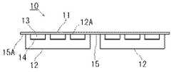
本発明を具体化した一実施形態について以下に説明する。 図1(a)及び図2に示すように、屋根パネル10は、野地合板11に断熱材12を接合することによって、該野地合板11と該断熱材12とを一体化して構成されたものである。該断熱材12は、該野地合板11の両面において前記断熱材12が接合される面の側を内側、該内側と反対側を外側として、該野地合板11の外側と内側の間の伝熱を妨げることで、前記屋根パネル10に断熱性能を付与するためのものである。 前記断熱材12は、矩形板状に形成されており、その上面が前記野地合板11の下面に接合されている。該断熱材12の上面には、複数(図中では3つ)の凹条12Aが、該断熱材12の長手方向に延びるように切削によって形成されている。そして、前記屋根パネル10には、前記野地合板11に前記断熱材12が接合された状態で、該野地合板の下面と、該断熱材12の上面に設けられた前記凹条12Aの内面とによって囲まれてなる通気層13が設けられている。該通気層13は、前記屋根パネル10を使用した屋根下地構造において、小屋裏換気のために設けられたものである(図5参照)。 前記凹条12Aの内底面には、金属薄膜が貼着されることにより、熱線反射層14が設けられている。該熱線反射層14は、日射による赤外線等の熱線を反射することで、輻射熱による該屋根パネル10そのものの温度上昇を抑制して、該屋根パネル10に遮熱性能を付与するためのものである(図5参照)。また該熱線反射層14は、前記通気層13の内底面を構成しているものであるから、該熱線反射層14の輻射熱が周囲の空気に伝熱されても、該空気は小屋裏換気のために設けられた該通気層13内のものであって、該通気層13を介して外部へ逃がされるので、良好な遮熱性能を発揮する。An embodiment embodying the present invention will be described below. As shown in FIG. 1A and FIG. 2, the
上記通気層13は、断熱材12の上面に凹条12Aを切削形成することによって設けることに限らず、野地合板11と断熱材12との間において屋根パネル10の内部に設けられているのであれば、次に示すような構成としてもよい。 すなわち、図1(b)に示すように、屋根パネル10は、該野地合板11の下面と該断熱材12の上面との間に複数の凸条13Aが介装されて構成されており、該複数の凸条13Aは、該断熱材12の上面に接合され、該野地合板11の下面に接合されている。そして、通気層13は、該野地合板の下面と、該断熱材12の上面と、一対の該凸条13Aの側面とによって囲まれて、屋根パネル10の内部に設けられている。 この構成の屋根パネル10にあっては、上記凹条12Aの内底面にそれぞれ金属薄膜を貼着したように、各一対の凸条13Aの間にそれぞれ金属薄膜を貼着して熱線反射層14を設けてもよいが、複数の凸条13Aを断熱材12の上面に接合する前に、予め断熱材12の上面の全体に金属薄膜を貼着しておくことで、通気層13の内底面に熱線反射層14を簡単かつ短時間で設けることが可能である(図1(b)参照)。 上記凸条13Aに使用する材料については、上記野地合板11と同じく合板を使用してもよく、また上記断熱材12と同じ材料を使用してもよい。 なお、通気層13を設ける他の手段として、上記野地合板11の下面を切削して凹条を形成してもよい。The
前記断熱材12は、該断熱材を介して家屋内の湿気を前記通気層13へ逃がすために、多孔質材からなるものとされており、前記屋根パネル10に透湿性能を付与している。該断熱材12に使用する多孔質材としては、ポリスチレン発泡体、フェノール樹脂発泡体、ポリエチレン発泡体、ポリプロピレン発泡体、半硬質ポリウレタン発泡体、メラミン樹脂発泡体等のプラスチック発泡体が挙げられる。 前記断熱材12は、前記屋根パネル10の透湿性能を所定以上のものとするべく、透湿比抵抗が0.70(m2・s・Pa)/ng以下とされている。該透湿比抵抗が0.70(m2・s・Pa)/ngを超える場合、前記熱線反射層14に透湿性を妨げられて所望とする透湿性能を発揮出来なくなる。また前記断熱材12は、上に挙げたプラスチック発泡体の中でも、透湿比抵抗を0.70(m2・s・Pa)/ng以下とするべく、ポリスチレン発泡体、フェノール樹脂発泡体を使用することが望ましい。なおJIS A 9511:2006R(発泡プラスチック保温材)の規格によれば、ポリスチレン発泡体は、A種押出法ポリスチレンフォーム(1種b、2種b、3種a、3種b)のスキンなしのもので透湿比抵抗が0,28(m2・s・Pa)/ngであり、A種フェノールフォーム(1種1号、1種2号)で透湿比抵抗が0,67(m2・s・Pa)/ngである。 なお断熱材12の透湿比抵抗は、低くなるほど屋根パネル10の透湿性能が向上するので好ましいが、0(m2・s・Pa)/ngにはならない。The
前記熱線反射層14を設けるのに使用される金属薄膜には、金属塊を打撃したり圧延したりすることによって箔状としたものが使用されており、該金属としてアルミニウム、銅、錫、亜鉛、ニッケル等が挙げられる。そして、該金属薄膜には、入手及び加工が容易であり、日射による熱線の反射性能が高いことから、アルミニウム薄膜を使用することが望ましい。 前記金属薄膜は、金属塊を打撃したり圧延したりすることによって箔状としたものであることから、該箔状のままで該金属薄膜を使用すると、前記熱線反射層14は前記断熱材12のような透湿性を有さず、前記断熱材12の透湿性を妨げてしまい、前記屋根パネル10が所望の透湿性能を有しないものとなってしまう。そこで該屋根パネルにあっては、熱線反射層14に複数の孔14Aを設けることで、該熱線反射層14に透湿性を付与している。 図3に示すように、前記熱線反射層14において、前記複数の孔14Aは、該熱線反射層14を厚み方向に貫通するのみならず、その先端部が該断熱材12の表層部分(凹条12Aの内底部)にま
で達しており、該表層部分に凹部12Bを形成している。このような孔14Aは、前記断熱材12の表面(あるいは凹条12Aの内底面)に金属薄膜を貼着した状態で、該金属薄膜の表面に、例えば表面に複数の針状体が突設されたロール等を押し付け、該針状体の先端部が該断熱材12の表層部分に達するまで突き刺すことによって、ピンホール状に形成される。また該孔14Aにおいては、前記針状体の突き刺し時に、その周縁にバリ14Bが形成されるが、該バリ14Bは前記断熱材12に形成された前記凹部12Bに収容されているから、該バリ14Bによって該孔14Aが塞がれることがなく、該孔14Aが良好かつ確実に開孔することで、好適な透湿性能を維持している。The metal thin film used to provide the heat ray
前記金属薄膜は、厚みが30μm〜70μmの範囲のものとされる。金属薄膜の厚みが30μmに満たない場合、一部の熱線が前記熱線反射層14を透過して前記断熱材12が輻射熱で熱くなるので遮熱性能が低下し、また該金属薄膜の耐久性が低く、前記屋根パネル10の製造時等において該金属薄膜が破れる等の不具合がある。金属薄膜の厚みが70μmを超える場合、孔を設ける等の加工がしづらくなり、また前記通気層13の空気の流量が少なくなり、十分に小屋裏換気をすることができなくなる。 前記熱線反射層14に透湿性を付与して、前記屋根パネル10の透湿性能を維持するべく、該熱線反射層の厚み50μmにおける透湿抵抗は、0.6×10⁻³(m2・s・Pa)/ng以下とされている。該透湿抵抗(厚み50μm)が0.6×10−3(m2・s・Pa)/ngを超える場合、前記屋根パネル10について所望の透湿性能が得られない。なお熱線反射層14の厚み50μmにおける透湿抵抗は、低くなるほど前記断熱材12の透湿性を阻害しないので好ましいが、該熱線反射層14を設ける以上、0(m2・s・Pa)/ngにはならない。 前記熱線反射層14の透湿抵抗(厚み50μm)を0.6×10⁻³(m2・s・Pa)/ng以下とするべく、該熱線反射層14に設けられた複数の孔14Aは、直径を1.5mm〜2.0mmの範囲内とすることが望ましく、該熱線反射層14上における密度を9,000〜9,500個/m2の範囲内とすることが望ましい。該孔14Aの直径が1.5mmに満たない、あるいは密度が9,000個/m2に満たない場合、前記熱線反射層14の透湿抵抗(厚み50μm)を0.6×10−3(m2・s・Pa)/ng以下とすることが難しくなる。複数の孔14Aは、直径が2.0mmを超える、あるいは密度が9,500個/m2を超える場合、前記熱線反射層14の透湿抵抗(厚み50μm)は0.6×10−3(m2・s・Pa)/ng以下となるが、熱線を反射可能な面積が減少してしまうので、遮熱性能が低下してしまうおそれがある。The metal thin film has a thickness in the range of 30 μm to 70 μm. When the thickness of the metal thin film is less than 30 μm, some heat rays pass through the heat ray
図1(a),(b)及び図2に示した、前記屋根パネル10は、家屋の設計データに基づいたCAD/CAM−システムを使用し、該家屋の屋根上で何れの位置に配置されるかを、つまり屋根上における配設位置を定めて製造されている。 すなわち、前記屋根パネル10は、1枚の野地合板11の下面に、2枚の断熱材12が、互いの間に間隔を空けて接合されている。該2枚の断熱材12の間隔は、屋根骨格を構成する垂木の幅と一致するように設定されており、該2枚の断熱材12の間は、該垂木を嵌合するための垂木嵌合溝15とされている。また前記屋根パネル10の両端部には、野地合板11の端部が断熱材12の端縁よりも所定幅だけ外側へ突出されれことにより、嵌合溝15Aが設けられている。該嵌合溝15Aにおける所定幅は、垂木の幅の1/2と一致するように設定されている。従って該嵌合溝15Aは、2枚の屋根パネル10の両端を互いに合わせた状態で、各屋根パネル10の該嵌合溝15A同士が合わさり、垂木嵌合溝15を形成する(図4参照)。The
前記屋根パネル10は、CAD/CAM−システムを使用し、配設位置を定めて製造されたものであるため、一棟の家屋に使用される全てが同じ構成になっているとは限らない。例えば、一部の屋根パネルは、1枚の野地合板11の下面に1枚の断熱材12のみが接合されて構成されていたり、あるいは野地合板11や断熱材12の横幅が他の屋根パネル10に比べて短くなっていたりする場合がある。よって、定められた位置以外に屋根パネル10を取り付けようとすれば、垂木に対する垂木嵌合溝15の位置がずれていたり、断熱材12を垂木間に嵌め込むことができなかったりする。そこで、該屋根パネル10には、下記の釘打位置指示手段や配置指示手段を設けることが望ましい。 前記野地合板11の上面には、垂木を嵌合するための前記垂木嵌合溝15と対応する位置に、釘打位置指示手段としての指示線16が付されている。該指示線16は、垂木に屋根パネル10が嵌められた状態において、外部から垂木の位置を示すためのものであり、CAD/CAM−システムを使用しての前記屋根パネル10の製造時に印刷されることで、該垂木の位置に正確に対応する。よって、該指示線16に従って釘を打ち込むことで、野地合板11を垂木に確実に釘打ちすることが可能である。なお、該釘打位置指示手段は、指示線16に限らず、外部から垂木の位置を示すことが可能であれば、浅溝や色付けや点描等としてもよい。 前記野地合板11の上面には、屋根上における該屋根パネル10の配設位置を示す配置指示手段としての番号17が付されている。該番号17は、屋根パネル10を後述する屋根骨格に敷設していく際に、取り付ける順番を示すことで、屋根パネル10の配設位置を表している。つまり、屋根骨格上で屋根パネル10の敷設を開始する始点は決まっているため、該始点から該番号17に従って屋根パネル10を順に取り付けていくことで、自ずと屋根パネル10を定められた位置に配設することが可能である。該番号17は、CAD/CAM−システムを使用しての前記屋根パネル10の製造時に印刷される。なお、該配置指示手段は、番号17に限らず、屋根パネル10の配設位置を示すことが可能であれば、アルファベットや図やシール等としてもよい。Since the
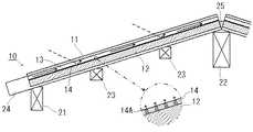
前記屋根パネル10は、複数が屋根骨格に取り付けられて、屋根下地構造を構成する。 図4及び図5に示すように、通常の家屋の屋根である切妻の屋根骨格では、屋根の軒先には軒桁21が、桁方向(図4中で紙面直交方向)へ延びるように、柱(図示略)によって下方から支持されている。また屋根の最も高いところには、棟木22が、屋根の延び方向(図4中で紙面直交方向)へ延びるように、小屋束(図示略)によって下方から支持されている。該軒桁21と該棟木22の間には、1本又は複数本の母屋23が、該棟木22と平行に延びるように配され、小屋束(図示略)によって下方から支持されている。そして、軒桁21と母屋23の上方には、垂木24が家屋の屋根の斜面方向に延びるように複数本配され、該軒桁21と母屋23によって下方から支持されている。 前記屋根パネル10の敷設作業は、上記切妻の屋根骨格上の始点から前記番号17に従って屋根パネル10を順番に並べ、垂木嵌合溝15を前記垂木に合わせ、該屋根パネル10を垂木24に被着していくという極めて簡易なものとなる。つまり、前記屋根パネル10は、CAD/CAM−システムを使用し、配設位置を定めて製造されたものであるから、垂木嵌合溝15を前記垂木24に合わせて嵌め込むのみで、野地合板11が垂木24の上に乗り、かつ断熱材12が複数本の垂木24の間に嵌め込まれる。 複数枚の前記屋根パネル10を屋根の斜面の上下方向で隣接させる必要がある場合、通常であれば各パネルの通気層13同士が連通するように取付位置の微調整が必要になる。しかし、上述したように前記屋根パネル10は、配設位置を定めたうえでCAD/CAM−システムを使用し、高精度に製造される。よって、野地合板11の寸法と、これに対応する断熱材12の寸法とが一致しており、前記垂木24に前記屋根パネル10を被着するのみで、上下に隣接する断熱材12同士が相互に接触し、かつ通気層13同士が相互に連通し、熱線反射層14同士が相互に繋がる。 また前記屋根パネル10の固定作業は、野地合板11の上面の指示線16に沿って釘Nを打ち込むのみであり、外部から見えない垂木24の位置を確認したり、探したりする必要がなく、これもまた極めて簡易なものとなる。 なお、屋根パネル10は、必ずしも縦長状のものが屋根下地構造を構成することに限らず、横長状のもので屋根下地構造を構成してもよい。つまり縦長状の屋根パネル10であれば、通気層13は該屋根パネル10(野地板11)の長手方向に沿って設けられ、また横長状の屋根パネル10であれば、通気層13は該屋根パネル10(野地板11)の短手方向に沿って設けられる。A plurality of the
前記屋根下地構造にあって、屋根の軒先において、前記屋根パネル10の通気層13は外部に向かって開放されている。屋根の棟部において、向かい合う屋根パネル10同士の間は、軟質ポリウレタン 発泡体、軟質ポリ塩化ビニル発泡体、合成ゴムスポンジ等の軟質プラスチック発泡体からなるシーリング材25によって隙間が埋められているが、該シーリング材25は前記屋根パネル10の棟側の通気層13を塞がないように設けられている。 該屋根下地構造にあっては、前記野地合板11の上面に瓦等の屋根材が敷設され、棟部に笠木や換気部材などが取り付けられて屋根が構成される。 該屋根にあっては、屋根パネル10の通気層13が軒先と棟とで外部に向かって開放されていることにより、該通気層13によって換気が行われる。また該通気層13の内底部には、前記熱線反射層14が設けられており、日射による熱線が該熱線反射層14で反射されるため、該熱線による屋根パネル10の温度上昇が抑えられている。更に該熱線反射層14には複数の孔14Aが設けられており、該孔14Aから通気層13へ湿気が逃がされるため、該熱線反射層14が断熱材12の透湿性を妨げることはない。In the roof base structure, the
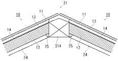
家屋の屋根にあっては、通常の切妻の他に、寄棟部31や本谷部32を有するものがある。 図6及び図7に示すように、寄棟部31を有する屋根は、該屋根の両端が内側に傾斜した形態となっており、該寄棟部31では垂木24間に隅木31Aが介在されている。該寄棟部31において、該隅木31Aを挟んで相互に対向する配設位置となる一対の屋根パネル10は、該寄棟部31に臨む断熱材12の端部がそれぞれ斜面状に切除されている。そして、該断熱材12の端部同士の間に、該隅木31Aが嵌合されている。 前記寄棟部31を有する屋根にあっては、通気層13の内底面(あるいは熱線反射層14の上面)と、前記隅木31Aの天端とを略一致させることにより、該通気層13が該隅木31Aによって閉塞されないようにしている。従って、該断熱材12の端部が切除された状態にあって、通気層13の機能は喪われておらず、更に該通気層13の内底面は上記したように熱線反射層14によって構成されているから、該熱線反射層14による遮熱性能も何等喪われていない。また熱線反射層14が上記したように薄いものであるため、通気層13の内底面と隅木31Aの天端とを一致させたとして、該熱線反射層14の厚みによって及ぼされる通気層13の通気への影響を略無視することが可能である。 なお前記寄棟部31を有する屋根においては、前記隅木31Aと前記断熱材12との間がシーリング材25によって家屋の屋内側から隙間が埋められている。また相互に対向する一対の屋根パネル10において、野地合板11の端部同士の間には間隙が設けられており、寄棟部31と屋根の棟部との間の通気を確保している。In the roof of a house, there are some which have the
図8及び図9に示すように、本谷部32を有する屋根は、例えば平面視で家屋がL字形となっている、あるいは一の屋根の何れかの箇所から分岐する分岐屋根を有する等のように、屋根と屋根の間に谷の部分を有する形態となっており、該本谷部32では垂木
24間に谷木32Aが介在されている。該本谷部32において、該谷木32Aを挟んで相互に対向する配設位置となる一対の屋根パネル10は、該本谷部32に臨む断熱材12の端部がそれぞれ斜面状に切除されている。そして、該断熱材12の端部同士の間に、該谷木32Aが嵌合されている。 前記本谷部32を有する屋根にあっては、通気層13の内底面(あるいは熱線反射層14の上面)と、前記谷木32Aの天端とを略一致させることにより、該通気層13が該谷木32Aによって閉塞されないようにしている。従って、該断熱材12の端部が切除された状態にあって、通気層13の機能は喪われておらず、更に該通気層13の内底面は上記したように熱線反射層14によって構成されているから、該熱線反射層14による遮熱性能も何等喪われていない。また熱線反射層14が上記したように薄いものであるため、通気層13の内底面と谷木32Aの天端とを一致させたとして、該熱線反射層14の厚みによって及ぼされる通気層13の通気への影響を略無視することが可能である。 なお前記本谷部32を有する屋根においては、前記谷木32Aと前記断熱材12との間がシーリング材25によって家屋の屋内側から隙間が埋められている。また相互に対向する一対の屋根パネル10において、野地合板11の端部同士の間には間隙が設けられており、本谷部32における通気を確保している。As shown in FIGS. 8 and 9, the roof having the
上記の寄棟部31や本谷部32を有する屋根において、使用される屋根パネル10は、上記したように家屋の設計データに基づいたCAD/CAM−システムを使用して製造されたものであり、このため前記断熱材12の端部の切除は、該屋根パネル10の製造時に行われる。このため作業現場において前記断熱材12の端部を隅木31Aや谷木32Aに合わせて切除しなくてもよく、屋根パネル10の敷設作業が極めて簡単なものとなっている。 また寄棟部31や本谷部32を有する屋根については、屋根パネル10の取り付けが隅棟や谷棟から順番に行われる。該屋根パネル10の取り付けの順番についても、前記配置指示手段としての番号17が付されることにより、間違いが起こりにくくなっている。In the roof having the above-mentioned
本発明の屋根パネルにあっては、所定の透湿性能と通気性能を維持しつつ所定の遮熱性能の付与を達成することができるとともに、屋根パネルの製造に係る手間の簡易化及び短時間化を図ることができるので、産業上利用可能である。Inthe roofpanel of the present invention, while maintaining a predetermined moisture permeability and breathability performance it is possible to achieve the application of certain thermal barrier performance, simplification of labor accordingto manufacturing roof panels and Since the time can be reduced, it can be used industrially.
10 屋根パネル 11 野地合板 12 断熱材 12A 凹条 13 通気層 13A 凸条 14 熱線反射層 14A 孔 14B バリ 15 垂木嵌合溝 15A 嵌合溝15A 16 指示線 17 番号 21 軒桁 22 棟木 23 母屋 24 垂木 25 シーリング材 31 寄棟部 31A 隅木 32 本谷部 32A 谷木DESCRIPTION OF
Claims (3)
Translated fromJapanesePriority Applications (1)
| Application Number | Priority Date | Filing Date | Title |
|---|---|---|---|
| JP2013051989AJP5756963B2 (en) | 2013-03-14 | 2013-03-14 | Roof panel |
Applications Claiming Priority (1)
| Application Number | Priority Date | Filing Date | Title |
|---|---|---|---|
| JP2013051989AJP5756963B2 (en) | 2013-03-14 | 2013-03-14 | Roof panel |
Related Child Applications (1)
| Application Number | Title | Priority Date | Filing Date |
|---|---|---|---|
| JP2015032828ADivisionJP5764790B1 (en) | 2015-02-23 | 2015-02-23 | Roof base structure |
Publications (2)
| Publication Number | Publication Date |
|---|---|
| JP2014177805A JP2014177805A (en) | 2014-09-25 |
| JP5756963B2true JP5756963B2 (en) | 2015-07-29 |
Family
ID=51698016
Family Applications (1)
| Application Number | Title | Priority Date | Filing Date |
|---|---|---|---|
| JP2013051989AActiveJP5756963B2 (en) | 2013-03-14 | 2013-03-14 | Roof panel |
Country Status (1)
| Country | Link |
|---|---|
| JP (1) | JP5756963B2 (en) |
Families Citing this family (1)
| Publication number | Priority date | Publication date | Assignee | Title |
|---|---|---|---|---|
| CN115233839B (en)* | 2022-06-09 | 2023-06-23 | 科顺防水科技股份有限公司 | Pre-laid waterproof coiled material |
Family Cites Families (3)
| Publication number | Priority date | Publication date | Assignee | Title |
|---|---|---|---|---|
| JP2003041675A (en)* | 2001-07-30 | 2003-02-13 | Paramount Glass Kogyo Kk | Insulation material provided with a projection for forming a ventilation layer |
| JP3682869B2 (en)* | 2001-12-10 | 2005-08-17 | 松本建工株式会社 | Residential roof insulation structure |
| JP5131731B2 (en)* | 2007-03-30 | 2013-01-30 | アキレス株式会社 | Roof insulation |
- 2013
- 2013-03-14JPJP2013051989Apatent/JP5756963B2/enactiveActive
Also Published As
| Publication number | Publication date |
|---|---|
| JP2014177805A (en) | 2014-09-25 |
Similar Documents
| Publication | Publication Date | Title |
|---|---|---|
| US9499986B2 (en) | System, method and apparatus for thermal energy management in a roof | |
| US8528284B2 (en) | Thermal energy venting system | |
| US20110265407A1 (en) | Above deck roofing ventilation system | |
| US9249571B1 (en) | Insulating system | |
| WO2008149090A1 (en) | Thermal insulation structure | |
| US10590653B1 (en) | Roof assemblies with inset solar panels, methods for their manufacture, and the use of such assemblies in a building | |
| JP5105628B2 (en) | Basic panel, exterior wall composite panel and roof composite panel for thermal insulation coating of wooden buildings | |
| JP5756963B2 (en) | Roof panel | |
| US20130276385A1 (en) | Insulating system | |
| US10570622B1 (en) | Roof assemblies, methods for their manufacture, and the use of such assemblies in a building | |
| JP5764790B1 (en) | Roof base structure | |
| JP4730973B2 (en) | Breathable heat insulating roof composite panel and wooden exterior heat insulating roof structure using the panel | |
| JP3690794B2 (en) | Insulated roof panel with integrated roof rafters | |
| JP3690793B2 (en) | Residential roof insulation structure and roof panel | |
| JPH1171835A (en) | Heat insulating structure and composite heat insulating material | |
| JP4743907B2 (en) | Breathable heat insulating roof composite panel and wooden exterior heat insulating roof structure using the panel | |
| JP2000136575A (en) | Waterproof building material and waterproofing method | |
| JP5335177B2 (en) | Insulation structure of roof | |
| JPH09235834A (en) | Heat insulating roof structure | |
| JP2003176595A (en) | Roof heat insulation structure of residence | |
| JP2003321885A (en) | External wall heat insulating structure using heat shield, and heat insulating panel | |
| JP7100490B2 (en) | Moisture permeable waterproof sheet with protrusions and its manufacturing method, as well as outer wall structure and construction method | |
| JPH09144156A (en) | Heat insulating roof structure and heat insulating panel | |
| JP3665302B2 (en) | Thermal insulation structure and heat insulation panel using outer wall | |
| JP2007247361A (en) | Roof panel and ventilating roof backing structure |
Legal Events
| Date | Code | Title | Description |
|---|---|---|---|
| A621 | Written request for application examination | Free format text:JAPANESE INTERMEDIATE CODE: A621 Effective date:20141024 | |
| A871 | Explanation of circumstances concerning accelerated examination | Free format text:JAPANESE INTERMEDIATE CODE: A871 Effective date:20141107 | |
| A975 | Report on accelerated examination | Free format text:JAPANESE INTERMEDIATE CODE: A971005 Effective date:20141217 | |
| A131 | Notification of reasons for refusal | Free format text:JAPANESE INTERMEDIATE CODE: A131 Effective date:20141225 | |
| A521 | Request for written amendment filed | Free format text:JAPANESE INTERMEDIATE CODE: A523 Effective date:20150223 | |
| TRDD | Decision of grant or rejection written | ||
| A01 | Written decision to grant a patent or to grant a registration (utility model) | Free format text:JAPANESE INTERMEDIATE CODE: A01 Effective date:20150325 | |
| A61 | First payment of annual fees (during grant procedure) | Free format text:JAPANESE INTERMEDIATE CODE: A61 Effective date:20150422 | |
| R150 | Certificate of patent or registration of utility model | Ref document number:5756963 Country of ref document:JP Free format text:JAPANESE INTERMEDIATE CODE: R150 | |
| R250 | Receipt of annual fees | Free format text:JAPANESE INTERMEDIATE CODE: R250 | |
| R250 | Receipt of annual fees | Free format text:JAPANESE INTERMEDIATE CODE: R250 | |
| R250 | Receipt of annual fees | Free format text:JAPANESE INTERMEDIATE CODE: R250 | |
| R250 | Receipt of annual fees | Free format text:JAPANESE INTERMEDIATE CODE: R250 |