JP5754074B2 - Image processing apparatus, image processing method, and program - Google Patents
Image processing apparatus, image processing method, and programDownload PDFInfo
- Publication number
- JP5754074B2 JP5754074B2JP2010063574AJP2010063574AJP5754074B2JP 5754074 B2JP5754074 B2JP 5754074B2JP 2010063574 AJP2010063574 AJP 2010063574AJP 2010063574 AJP2010063574 AJP 2010063574AJP 5754074 B2JP5754074 B2JP 5754074B2
- Authority
- JP
- Japan
- Prior art keywords
- image
- display
- group
- displayed
- images
- Prior art date
- Legal status (The legal status is an assumption and is not a legal conclusion. Google has not performed a legal analysis and makes no representation as to the accuracy of the status listed.)
- Expired - Fee Related
Links
Images


Classifications
- G—PHYSICS
- G09—EDUCATION; CRYPTOGRAPHY; DISPLAY; ADVERTISING; SEALS
- G09G—ARRANGEMENTS OR CIRCUITS FOR CONTROL OF INDICATING DEVICES USING STATIC MEANS TO PRESENT VARIABLE INFORMATION
- G09G5/00—Control arrangements or circuits for visual indicators common to cathode-ray tube indicators and other visual indicators
- G09G5/34—Control arrangements or circuits for visual indicators common to cathode-ray tube indicators and other visual indicators for rolling or scrolling
- G—PHYSICS
- G09—EDUCATION; CRYPTOGRAPHY; DISPLAY; ADVERTISING; SEALS
- G09G—ARRANGEMENTS OR CIRCUITS FOR CONTROL OF INDICATING DEVICES USING STATIC MEANS TO PRESENT VARIABLE INFORMATION
- G09G5/00—Control arrangements or circuits for visual indicators common to cathode-ray tube indicators and other visual indicators
- H—ELECTRICITY
- H04—ELECTRIC COMMUNICATION TECHNIQUE
- H04N—PICTORIAL COMMUNICATION, e.g. TELEVISION
- H04N23/00—Cameras or camera modules comprising electronic image sensors; Control thereof
- H04N23/60—Control of cameras or camera modules
- H04N23/63—Control of cameras or camera modules by using electronic viewfinders
- H04N23/633—Control of cameras or camera modules by using electronic viewfinders for displaying additional information relating to control or operation of the camera
- G—PHYSICS
- G06—COMPUTING OR CALCULATING; COUNTING
- G06F—ELECTRIC DIGITAL DATA PROCESSING
- G06F1/00—Details not covered by groups G06F3/00 - G06F13/00 and G06F21/00
- G06F1/16—Constructional details or arrangements
- G06F1/1613—Constructional details or arrangements for portable computers
- G06F1/1633—Constructional details or arrangements of portable computers not specific to the type of enclosures covered by groups G06F1/1615 - G06F1/1626
- G06F1/1684—Constructional details or arrangements related to integrated I/O peripherals not covered by groups G06F1/1635 - G06F1/1675
- G06F1/1694—Constructional details or arrangements related to integrated I/O peripherals not covered by groups G06F1/1635 - G06F1/1675 the I/O peripheral being a single or a set of motion sensors for pointer control or gesture input obtained by sensing movements of the portable computer
- G—PHYSICS
- G06—COMPUTING OR CALCULATING; COUNTING
- G06F—ELECTRIC DIGITAL DATA PROCESSING
- G06F3/00—Input arrangements for transferring data to be processed into a form capable of being handled by the computer; Output arrangements for transferring data from processing unit to output unit, e.g. interface arrangements
- G06F3/01—Input arrangements or combined input and output arrangements for interaction between user and computer
- G06F3/048—Interaction techniques based on graphical user interfaces [GUI]
- G06F3/0481—Interaction techniques based on graphical user interfaces [GUI] based on specific properties of the displayed interaction object or a metaphor-based environment, e.g. interaction with desktop elements like windows or icons, or assisted by a cursor's changing behaviour or appearance
- G06F3/0483—Interaction with page-structured environments, e.g. book metaphor
- G—PHYSICS
- G06—COMPUTING OR CALCULATING; COUNTING
- G06F—ELECTRIC DIGITAL DATA PROCESSING
- G06F3/00—Input arrangements for transferring data to be processed into a form capable of being handled by the computer; Output arrangements for transferring data from processing unit to output unit, e.g. interface arrangements
- G06F3/01—Input arrangements or combined input and output arrangements for interaction between user and computer
- G06F3/048—Interaction techniques based on graphical user interfaces [GUI]
- G06F3/0484—Interaction techniques based on graphical user interfaces [GUI] for the control of specific functions or operations, e.g. selecting or manipulating an object, an image or a displayed text element, setting a parameter value or selecting a range
- G06F3/0485—Scrolling or panning
- G—PHYSICS
- G09—EDUCATION; CRYPTOGRAPHY; DISPLAY; ADVERTISING; SEALS
- G09G—ARRANGEMENTS OR CIRCUITS FOR CONTROL OF INDICATING DEVICES USING STATIC MEANS TO PRESENT VARIABLE INFORMATION
- G09G5/00—Control arrangements or circuits for visual indicators common to cathode-ray tube indicators and other visual indicators
- G09G5/36—Control arrangements or circuits for visual indicators common to cathode-ray tube indicators and other visual indicators characterised by the display of a graphic pattern, e.g. using an all-points-addressable [APA] memory
- G—PHYSICS
- G09—EDUCATION; CRYPTOGRAPHY; DISPLAY; ADVERTISING; SEALS
- G09G—ARRANGEMENTS OR CIRCUITS FOR CONTROL OF INDICATING DEVICES USING STATIC MEANS TO PRESENT VARIABLE INFORMATION
- G09G2320/00—Control of display operating conditions
- G09G2320/06—Adjustment of display parameters
- G09G2320/068—Adjustment of display parameters for control of viewing angle adjustment
- G—PHYSICS
- G09—EDUCATION; CRYPTOGRAPHY; DISPLAY; ADVERTISING; SEALS
- G09G—ARRANGEMENTS OR CIRCUITS FOR CONTROL OF INDICATING DEVICES USING STATIC MEANS TO PRESENT VARIABLE INFORMATION
- G09G2354/00—Aspects of interface with display user
Landscapes
- Engineering & Computer Science (AREA)
- Theoretical Computer Science (AREA)
- General Engineering & Computer Science (AREA)
- Physics & Mathematics (AREA)
- Computer Hardware Design (AREA)
- General Physics & Mathematics (AREA)
- Human Computer Interaction (AREA)
- Multimedia (AREA)
- Signal Processing (AREA)
- Studio Devices (AREA)
- Controls And Circuits For Display Device (AREA)
- User Interface Of Digital Computer (AREA)
Description
Translated fromJapanese本発明は、画像処理装置に関し、特に、画像を表示させる画像処理装置および画像処理方法ならびに当該方法をコンピュータに実行させるプログラムに関する。 The present invention relates to an image processing apparatus, and more particularly to an image processing apparatus and an image processing method for displaying an image, and a program for causing a computer to execute the method.
近年、人物や動物等の被写体を撮像して画像データを生成し、この画像データを画像コンテンツとして記録するデジタルスチルカメラやデジタルビデオカメラ(例えば、カメラ一体型レコーダ)等の撮像装置が普及している。また、このように記録された各画像コンテンツを表示させる再生装置が多数提案されている。 In recent years, imaging devices such as a digital still camera and a digital video camera (for example, a camera-integrated recorder) that capture an image of a subject such as a person or an animal to generate image data and record the image data as image content have become widespread. Yes. In addition, many reproducing apparatuses for displaying each image content recorded in this way have been proposed.
例えば、操作部材を用いたユーザ操作により画像の画送りを行い、複数の画像を順次表示させる再生装置が存在する。また、ユーザが再生装置の姿勢を変化させることにより表示部の表示内容を変更させる再生装置が存在する。 For example, there is a playback device that performs image transfer by user operation using an operation member and sequentially displays a plurality of images. In addition, there is a playback device that changes the display content of the display unit when the user changes the attitude of the playback device.
例えば、本体の移動量や回転量を求め、これらに応じて表示部の表示内容のスクロール等を指示する情報処理装置が提案されている(例えば、特許文献1参照。)。 For example, there has been proposed an information processing apparatus that obtains the amount of movement and the amount of rotation of the main body and instructs the scrolling of the display content of the display unit in accordance with these (for example, see Patent Document 1).
上述の従来技術によれば、装置の姿勢を変化させることにより表示部の表示内容を変更させることができるため、ユーザがその装置を手で持った状態でその変更操作を行うことができる。 According to the above-described conventional technology, the display content of the display unit can be changed by changing the posture of the device, so that the user can perform the change operation while holding the device by hand.
ここで、複数の画像を装置の姿勢を変化させて画送りまたは画戻しさせる場合を想定する。この場合には、ユーザは表示部に順次表示される画像を見ながら、装置の姿勢を変化させる操作を行う。このため、ユーザが表示部に順次表示される画像を見ながら、画送りまたは画戻しのタイミングや画像群における表示画像の位置関係を容易に把握することができれば、その操作を容易に行うことができると考えられる。 Here, it is assumed that a plurality of images are changed in the posture of the apparatus to be sent or returned. In this case, the user performs an operation for changing the posture of the apparatus while viewing images sequentially displayed on the display unit. For this reason, if the user can easily grasp the image feed or image return timing and the positional relationship of the display images in the image group while watching the images sequentially displayed on the display unit, the operation can be easily performed. It is considered possible.
本発明はこのような状況に鑑みてなされたものであり、装置の姿勢を変化させる操作方法により複数の画像を順次表示させる場合にその操作を容易に行うことを目的とする。 The present invention has been made in view of such circumstances, and an object of the present invention is to easily perform an operation when a plurality of images are sequentially displayed by an operation method for changing the posture of the apparatus.
本発明は、上記課題を解決するためになされたものであり、その第1の側面は、表示部と、画像処理装置の姿勢の変化である傾け角度を検出する検出部と、上記傾け角度に基づいて複数の画像からなる画像群を構成する各画像を上記表示部に順次表示させるユーザ操作を支援するための情報であって、上記画像群の枚数によって上記姿勢の変化の範囲の中における各傾け角度と上記画像群を構成する各画像との関係が決定されるとともに、上記姿勢の変化の範囲の中における上記検出部で検出された上記傾け角度の位置を示す操作支援情報を、ユーザに提示する提示手段とを具備する画像処理装置および画像処理方法ならびに当該方法をコンピュータに実行させるプログラムである。これにより、操作支援情報をユーザに提示するという作用をもたらす。
The present invention has been made to solve the above problems, and a first aspect thereof includes a display unit, a detection unit that detects a tilt angle that is a change in the posture of the image processing apparatus, and the tilt angle. Information for supporting a user operation to sequentially display each image constituting an image group composed of a plurality of images on the display unit, and each of the images in the rangeof the posture change depending on the number of the image groups. The relationship between thetilt angle and each image constituting the image group is determined, and operation support information indicating the position of the tilt angle detected by the detection unit within the range of the posture change is given to the user. An image processing apparatus, an image processing method, and a program for causing a computer to execute the method. This brings about the effect | action of showing operation assistance information to a user.
また、この第1の側面において、上記提示手段は、上記画像群の枚数が基準を超えている場合には、上記画像群を構成する各画像のうちから、上記画像処理装置の傾け操作可能範囲に応じた所定数の画像を決定して表示対象画像とするようにしてもよい。これにより、画像群の枚数が基準を超えている場合には、画像群を構成する各画像のうちから、画像処理装置の傾け操作可能範囲に応じた所定数の画像を決定して表示対象画像とするという作用をもたらす。Further, in this first aspect, thepresenting means can tilt the image processing apparatus within a range in which the image processing apparatus can be operated from among the images constituting the image group when the number of the image group exceeds a reference. It is also possibleto determine a predetermined number of images corresponding to the display target image . As a result, whenthe number of image groups exceeds the reference, a predetermined number of images corresponding to the tiltable range of the image processing apparatus are determined from the images constituting the image group, and the display target images It brings about the effect of.
また、この第1の側面において、上記提示手段は、上記表示部に表示されている画像に対応する画像群の種類に基づいて上記操作支援情報の表示態様を上記画像群毎に変更して上記ユーザに提示するようにしてもよい。これにより、表示部に表示されている画像に対応する画像群の種類に基づいて、操作支援情報の表示態様を画像群毎に変更してユーザに提示するという作用をもたらす。In the first aspect, thepresenting means changes the display mode of the operation support information for each image group based on the type of the image group corresponding to the image displayed on the display unit, and You may makeit show to a user . Thereby, based on the kind of image group corresponding to the image currently displayed on thedisplay part, the display aspect of operation assistance information is changed for every image group, and the effect | actionof showing to a user is brought about.
また、この第1の側面において、上記提示手段は、上記操作支援情報を上記表示部に表示させることにより上記操作支援情報を上記ユーザに提示するようにしてもよい。これにより、操作支援情報を表示部に表示させるという作用をもたらす。In the first aspect, thepresenting means may present the operation support information to the user by displaying the operation support information on the display unit . This brings about the effect that theoperation support information is displayed on the display unit .
また、この第1の側面において、上記提示手段は、上記傾け角度に基づいて、上記画像群を表す代表画像を上記表示部に順次表示させ、上記表示部に表示された上記代表画像を選択するユーザ操作が行われた場合には、上記選択された代表画像に対応する画像群を構成する画像を上記表示部に表示させるようにしてもよい。これにより、傾け角度に基づいて代表画像を表示部に順次表示させ、表示部に表示された代表画像を選択するユーザ操作が行われた場合には、その選択された代表画像に対応する画像群を構成する画像を表示部に表示させるという作用をもたらす。In the first aspect, thepresenting means sequentially displays a representative image representing the image group on the display unit based on the tilt angle, and selects the representative image displayed on the display unit. When a user operation is performed, images constituting an image group corresponding to the selected representative image may bedisplayed on the display unit . Accordingly, whena user operation is performed to sequentially display the representative image on the display unit based on thetilt angle and select the representative image displayed on the display unit, an image group corresponding to the selected representative image. This brings about the effect thatthe image constituting the image is displayed on the display unit .
また、この第1の側面において、上記画像群を多視点画像からなるようにしてもよい。これにより、多視点画像からなる画像群を表示部に順次表示させるという作用をもたらす。In the first aspect, theimage group may becomposed of multi-viewpoint images . This brings about the effect | action ofdisplaying sequentially the image group which consists of amulti-viewpoint image on a display part .
また、この第1の側面において、上記操作支援情報は、円形状の標識であり、上記提示手段は、上記姿勢の変化の範囲の中における上記傾け角度の位置を、上記円形状の標識における円周上の位置により表すようにしてもよい。これにより、姿勢の変化の範囲の中における傾け角度の位置を、円形状の標識における円周上の位置により表すという作用をもたらす。Further, in this first aspect, theoperation support information is a circular sign, and the presenting means indicates the position of the tilt angle in the range of the change in the posture as a circle in the circular sign. It may berepresented by a position on the circumference . This brings about the effect thatthe position of the tilt angle within the range of change inposture is represented by the position on the circumference of the circular mark .
また、この第1の側面において、上記画像群を構成する画像の撮像動作時における撮像装置の撮像方向の角度に関する角度情報が当該画像に関連付けられているようにしてもよい。これにより、角度情報が関連付けられている画像を表示部に順次表示させるという作用をもたらす。In the first aspect,angle information related to the angle of the imaging direction of the imaging device during the imaging operation of the images constituting the image group may beassociated with the image . This brings about the effect | action that theimage with which angle information is linked | related is displayed on a display part one by one .
本発明によれば、装置の姿勢を変化させる操作方法により複数の画像を順次表示させる場合にその操作を容易に行うという優れた効果を奏し得る。 According to the present invention, when a plurality of images are sequentially displayed by an operation method that changes the posture of the apparatus, an excellent effect of easily performing the operation can be obtained.
以下、本発明を実施するための形態(以下、実施の形態と称する)について説明する。説明は以下の順序により行う。
1.第1の実施の形態(表示制御:グループ画像表示モードにおいて、グループに属する各画像にインジケータまたは傾き具合メータを重ねて表示する例)
2.変形例Hereinafter, modes for carrying out the present invention (hereinafter referred to as embodiments) will be described. The description will be made in the following order.
1. First embodiment (display control: an example in which an indicator or a tilt meter is displayed over each image belonging to a group in the group image display mode)
2. Modified example
<1.第1の実施の形態>
[撮像装置の外観構成例]
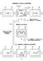
図1は、本発明の第1の実施の形態における撮像装置100の外観構成例を示す図である。図1(a)は、撮像装置100の表示面側の外観を示す斜視図である。また、図1(b)は、撮像装置100の表示面側の外観を示す側面図である。撮像装置100は、例えば、被写体を撮像して画像データを生成し、この画像データを画像コンテンツとして記録し、これらを表示することが可能なデジタルスチルカメラ、デジタルビデオカメラ(例えば、カメラ一体型レコーダ)等により実現される。<1. First Embodiment>
[External configuration example of imaging device]
FIG. 1 is a diagram illustrating an external configuration example of an
撮像装置100は、入出力パネル101およびシャッターボタン102を備える。また、撮像装置100は、ユーザが手に持って入出力パネル101に表示される画像を見ることができ、携帯することが可能な画像処理装置である。なお、撮像装置100は、特許請求の範囲に記載の画像処理装置の一例である。 The
入出力パネル101は、各種画像を表示するとともに、入出力パネル101における接触操作を検出することによりユーザからの操作入力を受け付けるものである。また、シャッターボタン102は、被写体を撮像して生成された画像データ(撮像画像)を画像コンテンツ(静止画ファイル)として記録する際に撮影者により押下されるボタンである。 The input /
なお、撮像装置100には、電源スイッチ、モード切替スイッチ等の他の操作部材やレンズ部等が備えられているが、説明の容易のため、ここでの図示および説明は省略する。ここで、レンズ部(図示せず)は、被写体からの光を集光する複数のレンズ、絞り等を備える光学系である。 Note that the
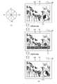
ここで、撮像装置100の姿勢の変化について説明する。例えば、ユーザが撮像装置100を手に持った状態で、直交3軸周りの回転角(すなわち、ヨー角、ピッチ角、ロール角)を変化させることができる。例えば、矢印300(矢印301)を軸とする矢印302方向に撮像装置100の姿勢を変化(ヨー角の変化)させることができる。この変化例を図2(b)に示す。また、例えば、矢印303(矢印304)を軸とする矢印305方向に撮像装置100の姿勢を変化(ピッチ角の変化)させることができる。また、例えば、矢印306(矢印307)を軸とする矢印308方向に撮像装置100の姿勢を変化(ロール角の変化)させることができる。 Here, a change in the posture of the
また、例えば、ユーザが撮像装置100を手に持った状態で、平面における直線上を移動(スライド)させて変化させることができる。例えば、矢印300または矢印301方向に移動させて変化させることができる(図1(b)における上下方向への移動)。また、例えば、矢印303または矢印304方向に移動させて変化させることができる(図1(b)における左右方向への移動)。この変化例を図2(c)に示す。また、例えば、矢印306または矢印307方向に移動させて変化させることができる。 Further, for example, the user can change the position by moving (sliding) on a straight line on a plane while holding the
[撮像装置の使用例]
図2は、本発明の第1の実施の形態における撮像装置100の使用時における姿勢の一例を示す図である。図2(a)には、撮像装置100を用いて画像コンテンツの再生を行う場合における撮像装置100の姿勢の一例を示す。人物310が、撮像装置100を用いて画像コンテンツの再生を行う場合には、例えば、図2(a)に示すように、撮像装置100を両手で持った状態で、入出力パネル101に表示される画像を見ることができる。[Usage example of imaging device]
FIG. 2 is a diagram illustrating an example of a posture during use of the
図2(b)および(c)には、撮像装置100の姿勢を変化させる場合におけるその遷移例を示す。図2(b)には、図1(a)に示す矢印300(301)を軸として矢印302の方向に撮像装置100を回転させてその姿勢を変化させる場合におけるその遷移例を示す。 2B and 2C show transition examples when the posture of the
図2(c)には、図1(a)および(b)に示す矢印303および304の方向に撮像装置100を移動させてその姿勢を変化させる場合におけるその遷移例を示す。本発明の第1の実施の形態では、このように撮像装置100の姿勢を変化させることにより、入出力パネル101に表示される画像を順次変更する例を示す。すなわち、ユーザによるジェスチャー操作により、入出力パネル101に表示される画像を順次変更する例を示す。これらの画像の表示状態の変更については、図6、図7等を参照して詳細に説明する。 FIG. 2C shows a transition example in the case where the posture is changed by moving the
[撮像装置の機能構成例]
図3は、本発明の第1の実施の形態における撮像装置100の機能構成例を示すブロック図である。撮像装置100は、入出力部110と、姿勢検出部120と、解析部130と、制御部140と、代表画像再生部150と、グループ画像再生部160と、描画メモリ170と、操作方法決定部180とを備える。また、撮像装置100は、画像コンテンツ記憶部200および画像管理情報記憶部210を備える。[Functional configuration example of imaging device]
FIG. 3 is a block diagram illustrating a functional configuration example of the
画像コンテンツ記憶部200は、撮像部(図示せず)により生成された画像データ(撮像画像)を画像ファイル(画像コンテンツ(静止画コンテンツまたは動画コンテンツ))として記憶するものである。また、画像コンテンツ記憶部200は、記憶されている画像コンテンツを代表画像再生部150またはグループ画像再生部160に供給する。なお、本発明の第1の実施の形態では、画像コンテンツとして静止画コンテンツを用いる例を示す。 The image
画像管理情報記憶部210は、画像コンテンツ記憶部200に記憶されている画像コンテンツに関する管理情報(画像管理情報)を記憶するものである。この画像管理情報を用いて、代表画像表示モードおよびグループ画像表示モードにおける再生が行われる。ここで、代表画像表示モードは、画像コンテンツ記憶部200に記憶されている画像コンテンツのうち、グループ化されている各画像コンテンツの代表画像と、グループ化されていない画像コンテンツの画像とをユーザ操作に応じて順次表示するモードである。また、グループ画像表示モードは、画像コンテンツ記憶部200に記憶されている画像コンテンツのうち、グループ化されている各画像コンテンツの画像を撮像装置100の姿勢の変化に応じて順次表示するモードである。なお、画像コンテンツ記憶部200および画像管理情報記憶部210として、例えば、DVD(Digital Versatile Disk)等のディスクやメモリカード等の半導体メモリ等のリムーバブルな1または複数の記録媒体を用いることができる。また、これらの記録媒体は、撮像装置100に内蔵するようにしてもよく、撮像装置100から着脱可能とするようにしてもよい。 The image management
入出力部110は、表示部111および操作受付部112を備える。表示部111は、代表画像再生部150またはグループ画像再生部160から供給された画像を表示する表示部である。また、表示部111には各種メニュー画面や各種画像が表示される。表示部111として、例えば、LCD(Liquid Crystal Display)、有機EL(Electro Luminescence)パネル等を用いることができる。 The input /
操作受付部112は、ユーザによって操作された操作内容を受け付ける操作受付部であり、受け付けられた操作内容に応じた操作信号を制御部140に供給する。操作受付部112は、例えば、図1に示すシャッターボタン102等の操作部材やタッチパネルに対応する。このタッチパネルは、例えば、表示部111の画面を透過するように表示部111に重ねて配置され、表示面に接触する物体を検出することによりユーザからの操作入力を受け付ける。すなわち、タッチパネルは、入出力部110における表示面において、ユーザが指を触れる等して所望の位置を押下すると、この押下位置の座標を検出し、この検出された座標に対応する操作信号を制御部140に出力する。そして、制御部140は、その操作信号を取得すると、取得された操作信号に基づいて所定の処理を実行する。操作受付部112として、例えば、専用の感知装置を用いて表示面における接触を電気信号に変換し、この変換された電気信号を制御部140に出力するタッチパネルを用いることができる。また、操作受付部112として、例えば、表示面に近接または接触する物体(例えば、ユーザの指)を検出することが可能な光センサ方式のタッチパネルを用いるようにしてもよい。なお、入出力部110は、図1に示すシャッターボタン102等の操作部材や入出力パネル101に対応する。 The
姿勢検出部120は、撮像装置100の加速度、動き、傾き等を検出することにより撮像装置100の姿勢の変化を検出するものであり、検出された姿勢の変化に関する姿勢変化情報を解析部130に出力する。例えば、姿勢検出部120は、撮像装置100の特定方向における移動方向および移動量、その特定方向における角速度(撮像装置100の姿勢が変化する際における角速度)等を、撮像装置100の姿勢の変化として検出する。なお、姿勢検出部120は、ジャイロセンサ(角速度センサ)や加速度センサにより実現することができる。なお、姿勢検出部120は、特許請求の範囲に記載の検出部の一例である。 The
解析部130は、姿勢検出部120から出力された姿勢変化情報に基づいて、撮像装置100の姿勢の変化量(移動方向、移動量等)を解析して表示部111に表示される画像や操作支援情報の表示切替を行うための解析情報を生成するものである。そして、解析部130は、その解析情報をグループ画像再生部160に出力する。 The
制御部140は、操作受付部112からの操作内容に基づいて、撮像装置100の各部を制御するものである。例えば、制御部140は、操作受付部112により代表画像表示モードの設定操作が受け付けられた場合には代表画像表示モードを設定し、操作受付部112によりグループ画像表示モードの設定操作が受け付けられた場合にはグループ画像表示モードを設定する。 The
また、制御部140は、グループ画像表示モードの設定操作が受け付けられた場合には、その設定操作時に表示部111に表示されていた代表画像に対応するグループを構成する各画像を、表示部111に順次表示させる制御を行う。このグループ画像表示モードの設定時には、制御部140は、撮像装置100の姿勢の変化と、表示部111における表示状態との関係を示す操作支援情報を表示部111に表示させる制御を行う。この操作支援情報は、表示部111における表示状態を変更するための操作を支援するための情報であり、例えば、図18(a)に示すインジケータ660や図19(a)に示す傾き具合メータ670である。また、制御部140は、操作方法決定部180により関連付けられた撮像装置100の姿勢の位置と、複数の画像コンテンツとに基づいてその操作支援情報を表示部111に表示させる制御を行う。 Further, when the setting operation of the group image display mode is accepted, the
また、代表画像表示モードが設定されている場合に、表示部111に表示される画像の表示切替(画送り、画戻し等)を指示する指示操作が受け付けられた場合には、制御部140は、その指示操作に基づいて画像の表示切替を代表画像再生部150に指示する。また、グループ画像表示モードの設定操作時には、制御部140は、その設定操作時に表示部111に表示されていた代表画像に対応するグループに関連付けられている画像管理情報(図4に示す操作方法215等)をグループ画像再生部160から取得する。制御部140は、例えば、CPU(Central Processing Unit)により実現される。 Further, when the representative image display mode is set, when an instruction operation for instructing display switching (image forwarding, image returning, etc.) of the image displayed on the
代表画像再生部150は、制御部140の制御に基づいて、画像コンテンツ記憶部200に記憶されている画像コンテンツのうち、代表画像に対応する画像コンテンツと、グループ化されていない画像コンテンツを表示部111に表示させるものである。具体的には、代表画像再生部150は、代表画像表示モードが設定されている場合に、代表画像に対応する画像コンテンツと、グループ化されていない画像コンテンツとを画像コンテンツ記憶部200から取得する。続いて、代表画像再生部150は、その取得された画像コンテンツをデコードし、このデコードされた画像コンテンツに基づいて表示用の画像を描画メモリ170に描画する。そして、代表画像再生部150は、制御部140の制御に基づいて、描画メモリ170に描画された各画像のうち、1つの画像を表示部111に順次表示させる。また、代表画像再生部150は、代表画像と、これに対応するグループを構成する各画像を表示させるためのグループ画像表示モードへの設定操作を支援する操作支援情報(例えば、図5に示す操作支援情報261)とを関連付けて表示部111に表示させる。さらに、代表画像再生部150は、代表画像と、これに対応するグループの種類(例えば、図4に示すグループ種類216)を表す操作支援情報(例えば、図5に示す操作支援情報251、252、256、257)とを関連付けて表示部111に表示させる。 Based on the control of the
グループ画像再生部160は、制御部140の制御に基づいて、画像コンテンツ記憶部200に記憶されている画像コンテンツのうち、グループ化されている画像コンテンツをグループ単位で表示部111に表示させるものである。具体的には、グループ画像再生部160は、グループ画像表示モードが設定された場合には、グループ画像表示モードの設定操作時に表示されていた代表画像に対応するグループに属する各画像コンテンツを画像コンテンツ記憶部200から取得する。また、グループ画像再生部160は、そのグループに属する各画像コンテンツに関連付けられている画像管理情報を画像管理情報記憶部210から取得する。続いて、グループ画像再生部160は、その取得された画像管理情報を操作方法決定部180に出力する。また、例えば、グループ画像再生部160は、その取得された画像コンテンツをデコードし、このデコードされた画像コンテンツに基づいて表示用の画像を描画メモリ170に描画する。この場合に、グループ画像再生部160は、例えば、所定の規則に従って表示用の各画像を並べて描画メモリ170に描画する。 Based on the control of the
また、グループ画像再生部160は、グループ画像表示モードの設定操作が受け付けられた場合には、表示対象となるグループに属する各画像と、操作支援情報とを関連付けて表示部111に表示させる。この場合に、例えば、グループ画像再生部160は、姿勢検出部120により検出された撮像装置100の姿勢の変化に基づいて、その操作支援情報の内容を変更させる。 Further, when a group image display mode setting operation is accepted, the group
描画メモリ170は、代表画像再生部150またはグループ画像再生部160により描画された画像を保持する描画バッファであり、描画された画像を代表画像再生部150またはグループ画像再生部160に供給する。 The
操作方法決定部180は、グループ画像再生部160から出力された画像管理情報に基づいて、グループ化されている画像コンテンツをグループ単位で表示部111に表示させる際における操作方法を決定するものである。例えば、操作方法決定部180は、撮像装置100の姿勢が変化する範囲を基準として、複数の画像コンテンツに付与されている角度情報を画像コンテンツ毎に正規化する。そして、操作方法決定部180は、その正規化された角度情報に基づいて、撮像装置100の姿勢の位置と、複数の画像コンテンツとを画像コンテンツ毎に関連付けて操作方法を決定し、この決定された操作方法をグループ画像再生部160に出力する。なお、この操作方法の決定方法については、図8乃至図14を参照して詳細に説明する。 Based on the image management information output from the group
[画像管理情報記憶部の記憶内容]
図4は、本発明の第1の実施の形態における画像管理情報記憶部210の記憶内容を模式的に示す図である。画像管理情報記憶部210には、グループ識別情報211と、画像コンテンツ識別情報212と、角度情報213と、代表画像214と、操作方法215と、グループ種類216とが記憶されている。[Storage contents of image management information storage unit]
FIG. 4 is a diagram schematically showing the storage contents of the image management
グループ識別情報211には、各グループを識別するための識別情報が格納されている。ここで、グループは、所定の規則に基づいて順序が特定されて互いに関連する複数の画像コンテンツにより構成される画像群である。なお、本発明の第1の実施の形態では、複数の画像コンテンツにより構成される画像群(グループ)と、画像群を構成しない画像コンテンツとの双方について、グループ識別情報を付与して、画像群を構成しない画像コンテンツと画像群とを識別する例を示す。 The
画像コンテンツ識別情報212には、画像コンテンツ記憶部200に記憶されている各画像コンテンツを識別するための識別情報(画像コンテンツ識別情報)が格納される。例えば、画送り、画戻しの順序(例えば、撮影時刻(記録日時)の順序)で、各画像コンテンツの画像コンテンツ識別情報が格納されているものとする。 The image
角度情報213には、画像コンテンツ記憶部200に記憶されている画像コンテンツが生成された際における撮像動作に対応する角度情報が格納される。例えば、撮像装置100を用いて多視点画像の撮影が行われ、この撮影により生成された多視点画像が画像コンテンツ記憶部200に記憶されている場合には、その撮影時における角度(所定位置を基準とした場合における角度)が角度情報として格納される。なお、角度情報が付与されていない画像コンテンツの欄には「無」を示す。ここで、多視点画像は、注目被写体(例えば、人物の顔)を基準として撮像装置100を移動させることにより、その注目被写体に対する視点を変化させる撮像動作により生成される複数の画像である。この撮像動作については、図8(a)を参照して詳細に説明する。 The
代表画像214には、グループ化されている複数の画像コンテンツのうちから、代表画像を特定するための代表画像情報が格納される。図4に示す例では、代表画像情報として、代表画像に対応する画像コンテンツの画像コンテンツ識別情報(画像コンテンツ識別番号)を示す。なお、グループ化されていない画像コンテンツの欄には「無」を示す。すなわち、代表画像214に画像コンテンツ識別情報が格納されているか否かにより、画像コンテンツがグループ化されているか否か(画像コンテンツがグループに属するか否か)を識別することができる。 The
操作方法215には、グループ画像表示モードが設定されている場合において、グループ化されている複数の画像コンテンツを順次表示する際における操作方法が格納される。この操作方法は、撮像装置100の姿勢の変化に関する操作方法である。例えば、「横回転」は、図1に示す矢印300(301)を軸として矢印302の方向に撮像装置100を回転させてその姿勢を変化させることにより、複数の画像コンテンツを順次表示させる操作を意味する。また、例えば、「縦回転」は、図1に示す矢印303(304)を軸として矢印305の方向に撮像装置100を回転させてその姿勢を変化させることにより、複数の画像コンテンツを順次表示させる操作を意味する。また、例えば、「水平移動」は、図1に示す矢印303および304の方向に撮像装置100を移動させてその姿勢を変化させることにより、複数の画像コンテンツを順次表示させる操作を意味する。また、例えば、「垂直移動」は、図1に示す矢印300および301の方向に撮像装置100を移動させてその姿勢を変化させることにより、複数の画像コンテンツを順次表示させる操作を意味する。この操作方法は、例えば、画像コンテンツの生成時における撮像動作方法に応じて、撮像装置100が自動で決定することができる。また、ユーザ操作によりユーザの好みに応じて適宜決定するようにしてもよい。 The
グループ種類216には、所定の規則に基づいて順序が特定されて互いに関連する複数の画像コンテンツにより構成されるグループ(画像群)に関する種類が格納される。図4では、「連写画像」および「多視点画像」がグループ種類として格納されている例を示す。ここで、「連写画像」は、連写撮影により生成された複数の画像により構成されるグループの種類であり、「多視点画像」は、多視点撮影により生成された複数の画像により構成されるグループの種類である。なお、グループ化されていない画像コンテンツの欄には「無」を示す。また、代表画像表示モードが設定されている場合に、代表画像とともに、グループ種類216の内容に基づいてその代表画像に対応するグループの種類を表示することができる。この表示例を図5に示す。 The
なお、グループ識別情報211、角度情報213、代表画像214、操作方法215およびグループ種類216に格納されている各情報については、画像ファイル(画像コンテンツ)内に記録するようにしてもよい。例えば、静止画ファイルに関する属性情報として、これらの各情報を記録することができる。そして、画像コンテンツの再生時には、画像コンテンツ内に記録されている各情報を用いることができる。 The information stored in the
[代表画像の表示例]
図5は、本発明の第1の実施の形態における代表画像再生部150により入出力パネル101に表示される代表画像の表示例を示す図である。図5(a)には、グループ種類216に「多視点画像」が格納されているグループの代表画像を表示する場合における表示例を示す。また、図5(b)には、グループ種類216に「連写画像」が格納されているグループの代表画像を表示する場合における表示例を示す。[Display example of representative image]
FIG. 5 is a diagram showing a display example of a representative image displayed on the input /
図5(a)に示すように、多視点画像に関するグループの代表画像250を入出力パネル101に表示する場合には、そのグループが多視点画像に関するグループである旨を示す操作支援情報(装飾画像)251および252が代表画像250の両側に表示される。また、代表画像250の上側には、グループ種類表示領域262および画サイズ表示領域263が設けられ、代表画像250の下側には、グループ画像表示モードを設定するための操作支援情報261が設けられている。 As shown in FIG. 5A, when the
グループ種類表示領域262には、表示されている代表画像に対応するグループの種類が表示される。例えば、表示されている代表画像に対応するグループの種類が、多視点画像に関するグループである場合には、グループ種類表示領域262には「多視点」が表示される。 The group
画サイズ表示領域263には、表示されている代表画像に対応するグループに属する各画像の画サイズ(例えば、1つの画像に関する画サイズ)が表示される。 In the image
操作支援情報261は、代表画像表示モードの設定時においてグループ画像表示モードを設定するための操作を支援するための操作ボタンである。すなわち、ユーザが操作支援情報261を押下することにより、グループ画像表示モードを設定することができる。また、操作支援情報261に対応する矩形内には、グループ種類表示領域262におけるグループの種類と同一の文字が表示される。 The
また、図5(b)に示すように、連写画像に関するグループの代表画像255を入出力パネル101に表示する場合には、そのグループが連写画像に関するグループである旨を示す操作支援情報(装飾画像)256、257が代表画像255の両側に表示される。また、代表画像255の上側には、グループ種類表示領域262および画サイズ表示領域263が設けられ、代表画像255の下側には、グループ画像表示モードを設定するための操作支援情報261が設けられている。 Further, as shown in FIG. 5B, when the
このように、代表画像表示モードが設定されている場合には、入出力パネル101に表示されている代表画像に係る画像群を構成する各画像の相関性(例えば、グループ種類に対応する)に基づいて、その代表画像の表示態様が画像群毎に変更して表示される。 In this way, when the representative image display mode is set, the correlation (for example, corresponding to the group type) of each image constituting the image group related to the representative image displayed on the input /
なお、図5(b)に示すように、表示されている代表画像に対応するグループの種類が、連写画像に関するグループである場合には、グループ種類表示領域262には「連写」が表示される。また、操作支援情報261に対応する矩形内には、「連写」が表示される。 As shown in FIG. 5B, when the group type corresponding to the displayed representative image is a group related to the continuous shot image, “continuous shooting” is displayed in the group
[画像の表示遷移例]
図6および図7は、本発明の第1の実施の形態における入出力パネル101における画像の表示遷移例を模式的に示す図である。図6(a)には、画像コンテンツ記憶部200に記憶されている画像コンテンツを所定の規則(画像コンテンツ識別情報の順序)に従って並べた場合を模式的に示す。なお、図6(a)に示す例では、画像コンテンツ記憶部200に記憶されている画像コンテンツのうち、画像コンテンツ#1乃至#13のみを示す。また、画像コンテンツ#1乃至#13は、図4の画像コンテンツ識別情報212に示す#1乃至#13に対応する。なお、図6では、画像コンテンツ識別情報(#1乃至#13)を内部に付した矩形により、各画像コンテンツおよびこれに対応する各画像を模式的に示す。また、グループ化されている画像コンテンツについては、グループ単位で各画像コンテンツを点線の矩形で囲んで示す。[Image display transition example]
6 and 7 are diagrams schematically showing display transition examples of images on the input /
図6(b)には、代表画像表示モードが設定されている場合に入出力パネル101に表示される画像の遷移例を示す。図6(b)に示すように、グループ化されていない画像コンテンツ(#1、#5、#6、#13)と、グループ化されている画像コンテンツの代表画像(#3、#9)とが、ユーザによる画送り操作または画戻し操作に基づいて順次表示される。この画送り操作または画戻し操作は、例えば、撮像装置100に備えられている操作部材(例えば、タッチパネルや外装されている操作ボタン(図示せず))を用いて行う。また、この画送り操作または画戻し操作は、例えば、グループ画像表示モードの設定時と同様に、撮像装置100の姿勢の変化に応じて行うようにしてもよい。 FIG. 6B shows an example of transition of images displayed on the input /
図7(a)には、図6(b)に示す画像のうち、画像コンテンツ#6、#9、#13が、ユーザによる画送り操作または画戻し操作に基づいて順次表示される場合における表示遷移例を示す。なお、図7では、画像コンテンツ識別情報(#6、#8乃至#10、#13)を内部に付した矩形により画像コンテンツを表す画像を模式的に示す。このように、ユーザ操作に基づいて各画像を入出力パネル101に表示させることができる。ここで、図7(a)に示すように、グループ化されている画像コンテンツの代表画像(例えば、#9)が、入出力パネル101に表示されている場合には、グループ画像表示モードを設定するための操作支援情報261が表示される。この操作支援情報261は、図5に示す操作支援情報261と同様である。すなわち、ユーザが操作支援情報261に対応する矩形領域を押下することにより、グループ画像表示モードを設定することができる。例えば、グループ化されている画像コンテンツ(例えば、#3、#9)の代表画像が入出力パネル101に表示されている状態で、操作支援情報261の押下操作が行われた場合にはグループ画像表示モードが設定される。このように、操作支援情報261の押下操作がグループ画像表示モードへの入り口となる。また、グループ画像表示モードが設定された場合には、グループ画像表示モードの設定操作(操作支援情報261の押下操作)が行われた際に表示されていた代表画像に対応するグループに属する各画像コンテンツが順次表示される。 FIG. 7A shows a display when
一方、図7(a)に示すように、グループ化されていない画像コンテンツ(例えば、#6、#13)が入出力パネル101に表示されている場合には、操作支援情報261が表示されない。このため、グループ化されていない画像コンテンツ(例えば、#6、#13)が入出力パネル101に表示されている状態では、操作支援情報261の押下操作が行うことができず、グループ画像表示モードを設定することができない。 On the other hand, as shown in FIG. 7A, when image content that is not grouped (for example, # 6 and # 13) is displayed on the input /
ここで、グループ化されている画像コンテンツ(#9)の代表画像が入出力パネル101に表示されている状態で、グループ画像表示モードの設定操作(操作支援情報261の押下操作)が行われた場合を想定する。この場合には、グループ画像再生部160が、グループ画像表示モードの設定操作が行われた際に表示されていた代表画像に対応するグループに属する各画像コンテンツを、画像コンテンツ記憶部200から取得する。また、グループ画像再生部160が、そのグループに属する各画像コンテンツに関連付けられている画像管理情報を、画像管理情報記憶部210から取得する。続いて、操作方法決定部180が、その取得された画像管理情報に基づいて、そのグループに属する各画像コンテンツから、表示対象となる画像(表示対象画像)を決定するとともに、これらの表示対象画像を表示させるための操作方法を決定する。この表示対象画像の決定方法およびその操作方法の決定方法については、図8乃至図14を参照して詳細に説明する。 Here, the group image display mode setting operation (the
続いて、グループ画像再生部160が、その決定された画像コンテンツに基づいて、各画像を描画メモリ170に描画する。この場合に、グループ画像再生部160は、所定の規則(例えば、画像コンテンツ識別情報の順序)に従って各画像を描画メモリ170に描画する。この描画メモリ170における画像の描画例を図6(c)に示す。 Subsequently, the group
図6(c)には、グループ画像表示モードが設定された際に表示されていた代表画像に対応するグループに属する各画像コンテンツが描画メモリ170に描画された場合を模式的に示す。このように画像コンテンツの描画処理が行われている場合には、グループ画像再生部160は、その旨を入出力パネル101に表示させ、グループ画像表示モードにおける表示処理を行わない。この場合における表示例を図7(b)に示す。なお、図6(b)では、グループ#105に属する各画像コンテンツの全てが、表示対象画像として決定された場合における描画例を示す。 FIG. 6C schematically shows a case where each image content belonging to the group corresponding to the representative image displayed when the group image display mode is set is drawn in the
図7(b)には、グループ画像表示モードの設定操作が行われた直後に画像コンテンツの描画処理が行われている場合における表示例を示す。例えば、入出力パネル101には、グループ画像表示モードが設定された際に表示されていた代表画像(#9)に、画像コンテンツの描画処理である旨を示す操作支援情報402が重ねて表示される。そして、画像コンテンツの描画処理が終了した場合には、グループ画像再生部160は、グループ画像表示モードにおける画像の表示切替操作を支援するための操作支援情報を入出力パネル101に表示させる。この表示例を図7(c)に示す。 FIG. 7B shows a display example when the image content drawing process is performed immediately after the group image display mode setting operation is performed. For example, on the input /
図7(c)には、グループ画像表示モードの設定操作後に画像コンテンツの描画処理が終了した場合における表示例を示す。例えば、入出力パネル101には、グループ画像表示モードが設定された際に表示されていた代表画像(#9)に、グループ画像表示モードにおける画像の表示切替操作を支援するための操作支援情報403および404が重ねて表示される。操作支援情報403および404は、入出力パネル101に表示されているグループに属する各画像を表示させるための操作を支援するための操作ガイドである。図7(c)に示す操作支援情報404は、ユーザが撮像装置100を手に持った状態で、図1(a)に示す矢印300(301)を軸として撮像装置100を回転させる操作を行う場合における操作を支援するためのものである。また、操作支援情報403は、最初に表示される操作支援情報であり、ユーザ操作または一定時間経過により消去させることができる。すなわち、そのメッセージの意味をユーザが理解したと考えられる場合には、そのメッセージを消去する。このように消去することにより、傾けるという操作が正しい操作であることをユーザに通知することができる。なお、各図では、説明の容易のため、各操作支援情報を比較的大きくして示す。 FIG. 7C shows a display example when the image content drawing process is completed after the group image display mode setting operation. For example, the
ここで、図7(c)に示すように、グループ画像表示モードが設定され、表示対象画像に重ねて操作支援情報403および404が表示されている状態で、代表画像表示モードを設定する設定操作について説明する。この状態で、代表画像表示モードを設定する場合には、例えば、ユーザが入出力パネル101における表示面に接触するタッチ操作を行う。このタッチ操作が行われると、矢印405に示すように、グループ画像表示モードから代表画像表示モードに切り替えられる(すなわち、代表画像表示モードが設定される)。このように代表画像表示モードが設定された直後には、グループ画像表示モードの設定時に表示されていたグループの代表画像(例えば、画像#9)が表示される。なお、入出力パネル101におけるタッチ操作以外に、他の操作部材を用いた設定操作により代表画像表示モードを設定するようにしてもよい。 Here, as shown in FIG. 7C, the setting operation for setting the representative image display mode in a state where the group image display mode is set and the
[角度情報の付与例]
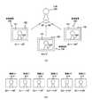
図8は、本発明の第1の実施の形態における撮像装置100を用いて行われる撮像動作時における被写体と撮像装置100との位置関係の概略と、その撮像動作時に生成された撮像画像群の一例とを示す図である。[An example of angle information]
FIG. 8 shows an outline of the positional relationship between the subject and the
図8(a)には、撮像装置100を用いて行われる撮像動作時における注目被写体(人物500の顔)と、撮像装置100との位置関係の概略を模式的に示す。図8(a)に示す例では、人物500の顔を注目被写体とし、撮像装置100を移動させることにより、人物500の顔に対する視点を変化させて撮像動作を行う例を示す。具体的には、図8(a)には、人物500の正面を撮影する場合(撮像動作時の角度情報Aiを0度とする場合)を示す。同様に、図8(a)には、人物500の右斜め側面を撮影する場合(撮像動作時の角度情報Aiを−60度とする場合)、人物500の左斜め側面を撮影する場合(撮像動作時の角度情報Aiを+60度とする場合)を示す。なお、図8(a)では、人物500(各画像に含まれる人物500を含む)に関する顔等を簡略化して示す。また、撮像装置100を用いて行われた撮像動作時の角度情報Aiを、撮像装置100の下部分に表す(Ai=−60度、Ai=0度、Ai=+60度)。 FIG. 8A schematically shows an outline of the positional relationship between the
図8(b)には、撮像装置100により生成された撮像画像群(画像(C0乃至C5)510乃至515)を示す。なお、Ciは、各画像を識別するための識別情報であり、iは0≦i≦nを満たす整数であるものとする。図8(b)に示す例では、n=5である。 FIG. 8B shows a captured image group (images (C0 to C5) 510 to 515) generated by the
具体的には、画像(C0乃至C2)510乃至512は、人物500の右斜め側面を撮影した場合(撮像動作時の角度情報Aiが−60度、−55度、−25度である場合)における撮像画像である。また、画像(C3乃至C5)513乃至515は、人物500の左斜め側面を撮影した場合(撮像動作時の角度情報Aiが+40度、+55度、+60度である場合)における撮像画像である。なお、図8(b)では、図8(a)と同様に、画像(C0乃至C5)510乃至515に含まれる人物500に関する顔等を簡略化して示す。また、撮像動作時の角度情報Ai(画像Ciの撮像動作時における角度)については、各画像の下部分に表す(A0=−60度、A1=−55度、…、A4=+55度、A5=+60度)。 Specifically, images (C0 to C2) 510 to 512 are obtained when the right side surface of the
このように、注目被写体(人物500の顔)に対する視点を変化させることにより生成された画像(C0乃至C5)510乃至515については、多視点画像としてグループ化され、画像コンテンツ記憶部200に記憶される。また、これらの各画像管理情報(例えば、角度情報、グループ種類)が画像管理情報記憶部210に記憶される。そして、撮像装置100を用いて画像(C0乃至C5)510乃至515を表示させる場合には、撮像装置100を横回転させることにより、そのグループを構成する画像(C0乃至C5)510乃至515を順次表示させることができる。 As described above, the images (C0 to C5) 510 to 515 generated by changing the viewpoint with respect to the subject of interest (the face of the person 500) are grouped as multi-view images and stored in the image
ここで、画像(C0乃至C5)510乃至515は、同一人物の顔について異なる視点から撮像された画像である。このため、撮像装置100を左右に傾けるユーザ操作を早く行い、画送りまたは画戻しを早く行うことにより、3次元の物体(人物500の顔)を見ているようにユーザに認識させることができる。すなわち、撮像装置100を左右に傾けるユーザ操作により、擬似的に3次元画像を見ているようにユーザに認識させることができる。 Here, the images (C0 to C5) 510 to 515 are images taken from different viewpoints of the face of the same person. For this reason, the user can recognize the user as if he / she is looking at a three-dimensional object (the face of the person 500) by quickly performing a user operation for tilting the
このように、注目被写体がさまざまな角度から撮影された画像群をユーザのジェスチャー操作により高速画送りまたは画戻しをさせることにより、擬似立体視のような画像を奥行きのある画像として楽しむことができる。すなわち、人物の顔や車等の対象物を立体的に鑑賞したい場合に、ユーザの手動操作によりその対象物の擬似的な立体画像を容易に鑑賞することができる。 As described above, by causing the user to perform high-speed image feed or image return by performing a user's gesture operation on an image group in which the subject of interest is photographed from various angles, an image such as pseudo-stereoscopic view can be enjoyed as a deep image. . That is, when it is desired to view an object such as a person's face or a car in three dimensions, a pseudo three-dimensional image of the object can be easily viewed by a user's manual operation.
このように画像群を表示させる場合には、その操作方法に係る角度情報(回転角度の全範囲および基準角度)の決定が重要である。そこで、以下では、その操作方法に係る角度情報の決定方法について図面を参照して詳細に説明する。 When displaying an image group in this manner, it is important to determine angle information (the entire range of rotation angles and the reference angle) related to the operation method. Therefore, hereinafter, a method for determining angle information according to the operation method will be described in detail with reference to the drawings.
[角度情報の正規化例]
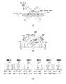
図9は、本発明の第1の実施の形態における撮像装置100の姿勢の変化と操作方法決定部180により行われる角度情報の正規化の一例を示す図である。図9(a)には、グループ画像表示モードが設定されている場合において、画像コンテンツ記憶部200に記憶されている画像コンテンツを表示する場合における撮像装置100の遷移例を示す。なお、図9(a)に示す例では、撮像装置100の底面(すなわち、シャッターボタン102が設けられている面の反対側の面)側の外観を示す。また、図9(b)、図10(b)、図13(a)についても同様に、撮像装置100の底面側の外観を示す。[An example of normalization of angle information]
FIG. 9 is a diagram illustrating an example of normalization of angle information performed by the change in posture of the
図9(b)には、撮像装置100の遷移に対応する撮像装置100の操作範囲(回転角度の全範囲)を模式的に示す。この例では、図1に示す矢印300(301)を軸として撮像装置100を回転させてその姿勢を変化させることにより画送りまたは画戻しを行う例を示す。この場合における画送りまたは画戻しの際に基準となる傾け角度(基準角度)をViとする。この傾け角度Viは、次の式1により求めることができる。
Vi=γ×j … 式1
ここで、γは、手ブレ等がなく、人の手で維持することができる傾け精度を示す値である。これらの値は、姿勢検出部120(傾き検出装置)の精度や性能を考慮して決定することができる。また、jは、(−m≦j≦mの整数)を満たす値であり、iは、0≦i≦nを満たす整数であるものとする。図9(b)に示す例では、n=4である。FIG. 9B schematically illustrates the operation range (the entire range of the rotation angle) of the
Vi = γ ×
Here, γ is a value indicating the tilt accuracy that can be maintained by a human hand without camera shake or the like. These values can be determined in consideration of the accuracy and performance of the posture detection unit 120 (tilt detection device). Further, j is a value satisfying (an integer satisfying −m ≦ j ≦ m), and i is an integer satisfying 0 ≦ i ≦ n. In the example shown in FIG. 9B, n = 4.
ここで、画像群を構成する各画像Ciに付与された角度情報Aiは、撮像動作時における注目被写体に対する角度である。このため、角度情報Aiに基づいて、各画像Ciと、傾け角度Viとを関連付けることが好ましい。そこで、角度情報Aiが傾け角度Viに対応するように、角度情報Aiについて正規化が行われる。具体的には、角度情報Aiが正規化された正規化角度情報Biは、次の式2により求めることができる。
Bi=(Vmax/Aabs)×Ai … 式2
ここで、Vmaxは、最大傾け角度の絶対値であり、使用者が表示画面を見ることが可能な角度とする。Vmaxは、例えば、画面の視野角等に制限される。また、Aabsは、角度情報Aiの範囲を示す値(絶対値)である。Here, the angle information Ai given to each image Ci constituting the image group is an angle with respect to the subject of interest during the imaging operation. For this reason, it is preferable to associate each image Ci with the tilt angle Vi based on the angle information Ai. Therefore, the angle information Ai is normalized so that the angle information Ai corresponds to the tilt angle Vi. Specifically, the normalized angle information Bi obtained by normalizing the angle information Ai can be obtained by the
Bi = (Vmax / Aabs) ×
Here, Vmax is an absolute value of the maximum tilt angle, and is an angle at which the user can see the display screen. Vmax is limited to, for example, the viewing angle of the screen. Aabs is a value (absolute value) indicating the range of the angle information Ai.
図9(b)に示す例では、Vmax=180°とし、γ=45°とし、m=2(すなわち、−2≦j≦2)とする例を示す。また、角度情報Aiの範囲は、画像(C0)510の角度情報A0(=−60度)と、画像(C5)515の角度情報A5(=+60度)とにより特定される。すなわち、Aabs=|−60°−60°|=120°となる。 The example shown in FIG. 9B shows an example in which Vmax = 180 °, γ = 45 °, and m = 2 (that is, −2 ≦ j ≦ 2). The range of the angle information Ai is specified by the angle information A0 (= −60 degrees) of the image (C0) 510 and the angle information A5 (= + 60 degrees) of the image (C5) 515. That is, Aabs = | −60 ° −60 ° | = 120 °.
このため、図9(b)に示す例では、B0=(180°(Vmax)/120°(Aabs))×(−60°(A0))=−90°となる。同様に、B1=−82.5°、B2=−37.5°、B3=60°、B4=82.5°、B5=90°となる。これらの正規化角度情報Biが、操作方法決定部180により算出される。 For this reason, in the example shown in FIG. 9B, B0 = (180 ° (Vmax) / 120 ° (Aabs)) × (−60 ° (A0)) = − 90 °. Similarly, B1 = −82.5 °, B2 = −37.5 °, B3 = 60 °, B4 = 82.5 °, and B5 = 90 °. The normalized angle information Bi is calculated by the operation
図9(c)には、画像(C0乃至C5)510乃至515と、これらに付与されている角度情報Aiおよびこれらについて算出された正規化角度情報Biとを関連付けて示す。 FIG. 9C shows the images (C0 to C5) 510 to 515, the angle information Ai given thereto, and the normalized angle information Bi calculated for these in association with each other.
このように画像Ciに関連付けられている撮像動作時における角度情報を正規化することにより、傾け角度(基準角度)Viに画像Ciを適切に割り当てることができる。 Thus, by normalizing the angle information at the time of the imaging operation associated with the image Ci, the image Ci can be appropriately assigned to the tilt angle (reference angle) Vi.
[表示対象画像と傾け角度との関連付け例]
図10は、本発明の第1の実施の形態における操作方法決定部180による表示対象画像と傾け角度の範囲との関連付け方法およびこの関連付け後に表示される画像および操作支援情報の一例を示す図である。図10(a)および(b)には、操作方法決定部180による表示対象画像と傾け角度の範囲との関連付け方法を模式的に示す。[Example of associating display target image with tilt angle]
FIG. 10 is a diagram illustrating an example of a method of associating a display target image with a tilt angle range by the operation
図10(a)には、画像(C0乃至C5)510乃至515と、これらに付与されている角度情報Aiおよびこれらについて算出された正規化角度情報Biとを関連付けて示す。なお、図10(a)に示す例は、画像(C1)511に対応する矩形および人物500に対応する輪郭を点線で表す点以外は、図9(c)と同一である。 FIG. 10A shows the images (C0 to C5) 510 to 515 in association with the angle information Ai given thereto and the normalized angle information Bi calculated for them. Note that the example shown in FIG. 10A is the same as FIG. 9C except that the rectangle corresponding to the image (C1) 511 and the outline corresponding to the
図10(b)には、撮像装置100の遷移に対応する撮像装置100の操作範囲(回転角度の全範囲)を模式的に示す。なお、図10(b)に示す例は、図9(b)に示す例と同様である。 FIG. 10B schematically shows the operation range (the entire range of the rotation angle) of the
ここで、図10(a)および(b)に示す例では、画像(C0乃至C5)510乃至515の数(6)が、傾け角度(基準角度)Viの数(5)よりも大きい。このように表示対象グループに属する画像の数が、傾け角度(基準角度)Viの数よりも大きい場合には、表示対象グループに属する画像について間引き処理が行われる。すなわち、操作方法決定部180が、傾け角度(基準角度)Viの数の範囲内となるように、表示対象グループに属する画像から所定数の画像を表示対象画像として抽出する。 Here, in the example shown in FIGS. 10A and 10B, the number (6) of the images (C0 to C5) 510 to 515 is larger than the number (5) of the tilt angles (reference angles) Vi. In this way, when the number of images belonging to the display target group is larger than the number of tilt angles (reference angles) Vi, thinning processing is performed on images belonging to the display target group. That is, the operation
具体的には、正規化角度情報Biが算出された画像群(画像Ci(0≦i≦n))の中から、傾け角度(基準角度)Viに最も近い正規化角度情報Biに係る画像Ciを傾け角度(基準角度)Vi毎に選択して画像CCiとする。 Specifically, the image Ci related to the normalized angle information Bi closest to the tilt angle (reference angle) Vi from the image group (image Ci (0 ≦ i ≦ n)) from which the normalized angle information Bi is calculated. Is selected for each tilt angle (reference angle) Vi to obtain an image CCi.
図10(a)および(b)では、傾け角度(基準角度)V0からV4に向かって、傾け角度(基準角度)Viに最も近い正規化角度情報Biに係る画像Ciが選択され、選択された画像Ciと傾け角度(基準角度)Viとが関連付けられる例を示す。 In FIGS. 10A and 10B, the image Ci related to the normalized angle information Bi closest to the tilt angle (reference angle) Vi from the tilt angle (reference angle) V0 to V4 is selected and selected. An example in which an image Ci and an inclination angle (reference angle) Vi are associated with each other will be described.
具体的には、傾け角度V0(=−90°)に最も近い正規化角度情報B0(=−90°)に係る画像C0が選択され、画像CC0として傾け角度V0に関連付けられる。同様に、傾け角度V1(=−45°)に最も近い正規化角度情報B2(=−37.5°)に係る画像C2が選択され、画像CC1として傾け角度V1に関連付けられる。また、傾け角度V2(=0°)に最も近い正規化角度情報B3(=+60°)に係る画像C3が選択され、画像CC2として傾け角度V2に関連付けられる。また、傾け角度V3(=45°)に最も近い正規化角度情報B4(=+82.5°)に係る画像C4が選択され、画像CC3として傾け角度V3に関連付けられる。また、傾け角度V4(=90°)に最も近い正規化角度情報B5(=+90°)に係る画像C5が選択され、画像CC4として傾け角度V4に関連付けられる。 Specifically, the image C0 related to the normalized angle information B0 (= −90 °) closest to the tilt angle V0 (= −90 °) is selected, and is associated with the tilt angle V0 as the image CC0. Similarly, the image C2 related to the normalized angle information B2 (= −37.5 °) closest to the tilt angle V1 (= −45 °) is selected, and is associated with the tilt angle V1 as the image CC1. Further, the image C3 related to the normalized angle information B3 (= + 60 °) closest to the tilt angle V2 (= 0 °) is selected, and is associated with the tilt angle V2 as the image CC2. Further, the image C4 related to the normalized angle information B4 (= + 82.5 °) closest to the tilt angle V3 (= 45 °) is selected, and is associated with the tilt angle V3 as the image CC3. Also, the image C5 related to the normalized angle information B5 (= + 90 °) closest to the tilt angle V4 (= 90 °) is selected, and is associated with the tilt angle V4 as the image CC4.
すなわち、画像群(画像Ci(0≦i≦5))の中から、CCi(=[C0,C2,C3,C4,C5]=[CC0,CC1,CC2,CC3,CC4])が選択される。 That is, CCi (= [C0, C2, C3, C4, C5] = [CC0, CC1, CC2, CC3, CC4]) is selected from the image group (image Ci (0 ≦ i ≦ 5)). .
このように選択されて傾け角度Viに関連付けられた各画像CCiが、撮像装置100の傾きに応じて順次表示される。例えば、撮像装置100の姿勢が、傾け角度(基準角度)Viの状態にある場合には、傾け角度(基準角度)Viに関連付けられている画像CCiが表示される。そして、撮像装置100の姿勢が、傾け角度(基準角度)Vi−1または傾け角度(基準角度)Vi+1になるまでの間、画像CCiが表示され続ける。 Each image CCi selected in this way and associated with the tilt angle Vi is sequentially displayed according to the tilt of the
図10(c)には、図10(a)および(b)に示す関連付け方法により傾け角度Viに関連付けられた各画像CCiを入出力パネル101に表示する場合における表示例を示す。図10(c)に示す例では、表示対象画像(傾け角度Viに関連付けられた画像CCi)に操作支援情報520を重ねて表示させる例を示す。 FIG. 10C shows a display example when each image CCi associated with the tilt angle Vi is displayed on the input /
操作支援情報520は、グループ画像表示モードが設定されている場合において、表示対象となるグループに属する画像(抽出された全ての表示対象画像)と、入出力パネル101に表示されている画像との関係を表すインジケータである。具体的には、操作支援情報520は、抽出された全ての表示対象画像(C0、C2乃至C5)510、512乃至515と、入出力パネル101に表示されている1つの画像との関係を表す。例えば、全ての画像(C0、C2乃至C5)510、512乃至515のうち、入出力パネル101に表示されている1つの画像に対応する操作支援情報520における矩形領域が、他の領域と異なる表示態様とされる。なお、図10(c)に示す例では、説明の容易のため、操作支援情報520を表す矩形内に、対応する符号(V0乃至V4)を付して示す。 When the group image display mode is set, the
すなわち、図10(c)に示す状態では、表示対象画像(C0、C2乃至C5)510、512乃至515のうち、画像(C3)513が入出力パネル101に表示されている状態を示す。また、撮像装置100が左側方向に回転され、図10(b)に示すV1を超えた状態となった場合には、操作支援情報520における矩形領域V1が、他の領域と異なる表示態様とされる。また、撮像装置100が左側方向にさらに回転され、図10(b)に示すV0を超えた状態となった場合には、操作支援情報520における矩形領域V0が、他の領域と異なる表示態様とされる。一方、撮像装置100が右側方向に回転され、図10(b)に示すV3、V4を超えた状態となった場合についても同様に、操作支援情報520における矩形領域V3、V4が、他の領域と異なる表示態様とされる。 That is, in the state shown in FIG. 10C, the image (C3) 513 is displayed on the input /
このようにグループ画像表示モードが設定されている場合に、表示対象画像とともにインジケータを表示することにより、表示対象画像の全体の数と、この表示対象画像の全体における表示画像の位置(表示順における位置)を容易に把握することができる。 When the group image display mode is set in this way, by displaying the indicator together with the display target image, the total number of display target images and the position of the display image in the entire display target image (in the display order). Position) can be easily grasped.
以上では、各画像に付与されている角度情報を正規化して、一定間隔の角度に各画像を割り当てて、その角度に応じて各画像を表示する例を示した。ただし、その算出された各画像の正規化角度情報の間隔に応じて、傾け角度(基準角度)を決定して、その角度に応じて各画像を表示するようにしてもよい。また、操作支援情報として、インジケータを表示する場合には、その算出された各画像の正規化角度情報の間隔に応じて、インジケータの表示領域を算出するようにしてもよい。このインジケータの表示領域の算出方法および表示例を、図11および図12に示す。 In the above, an example has been shown in which the angle information given to each image is normalized, each image is assigned to an angle of a fixed interval, and each image is displayed according to the angle. However, the tilt angle (reference angle) may be determined according to the calculated interval of the normalized angle information of each image, and each image may be displayed according to the angle. When an indicator is displayed as the operation support information, the indicator display area may be calculated according to the calculated interval of the normalized angle information of each image. The calculation method and display example of the display area of this indicator are shown in FIGS.
[インジケータ表示の変形例]
図11は、本発明の第1の実施の形態における操作方法決定部180によるインジケータの表示領域の算出方法を模式的に示す図である。[Modification of indicator display]
FIG. 11 is a diagram schematically illustrating a method of calculating the indicator display area by the operation
図11(a)には、画像(C0乃至C5)510乃至515と、これらに付与されている角度情報Aiおよびこれらについて算出された正規化角度情報Biとを関連付けて示す。なお、図11(a)に示す例は、図10(a)と同一であるため、ここでの説明を省略する。 FIG. 11A shows the images (C0 to C5) 510 to 515 in association with the angle information Ai given thereto and the normalized angle information Bi calculated for them. In addition, since the example shown to Fig.11 (a) is the same as that of Fig.10 (a), description here is abbreviate | omitted.
図11(b)には、算出された表示領域とインジケータとの関係を模式的に示す。例えば、操作方法決定部180が、画像(C0乃至C5)510乃至515について算出された正規化角度情報Biについてさらに正規化を行う。具体的には、操作方法決定部180が、正規化角度情報BBi(=CCiの正規化角度情報+90度)を算出する。そして、正規化角度情報BBiを用いてインジケータの表示領域Wiを次の式3により求めることができる。
Wi=BBi/Vmax×L …式3
ここで、Lは、入出力パネル101に表示されるインジケータの長さを示す値である。また、BBiは、上述した正規化により算出された値である。FIG. 11B schematically shows the relationship between the calculated display area and the indicator. For example, the operation
Wi = BBi / Vmax
Here, L is a value indicating the length of the indicator displayed on the input /
ここで、インジケータの表示領域Wiは、図11(b)に示すインジケータ(長さL)における左側の端部からの長さを示す値である。このように算出されたインジケータの表示領域Wiに基づく表示例を図12に示す。 Here, the indicator display area Wi is a value indicating the length from the left end of the indicator (length L) shown in FIG. A display example based on the indicator display area Wi calculated in this way is shown in FIG.
図12は、本発明の第1の実施の形態における操作方法決定部180により算出されたインジケータの表示領域に基づくインジケータの表示例を示す図である。 FIG. 12 is a diagram illustrating a display example of an indicator based on the display area of the indicator calculated by the operation
図12(a)には、図11に示す例で算出された表示領域Wiとインジケータとの関係を模式的に示す。なお、図12(a)に示す例は、図11に示す例で算出された表示領域Wiにより特定されるインジケータ上の位置に対応する各矩形内に、画像の符号(C0、C2乃至C5)を付した点以外は、図11(b)と同様である。 FIG. 12A schematically shows the relationship between the display area Wi calculated in the example shown in FIG. 11 and the indicator. In the example shown in FIG. 12A, the code (C0, C2 to C5) of the image is included in each rectangle corresponding to the position on the indicator specified by the display area Wi calculated in the example shown in FIG. Except for the points marked with, it is the same as FIG.
図12(b)には、図12(a)に示す表示領域Wiとインジケータとの関係に対応するインジケータ(操作支援情報)530が入出力パネル101に表示されている状態を示す。図12(b)に示す例では、画像(C3)513に対応する領域が、他の領域と異なる表示態様とされている状態を示す。 FIG. 12B shows a state in which an indicator (operation support information) 530 corresponding to the relationship between the display area Wi and the indicator shown in FIG. The example shown in FIG. 12B shows a state where the area corresponding to the image (C3) 513 has a different display mode from the other areas.
図12(c)乃至(f)には、図12(a)に示す表示領域Wiとインジケータとの関係に対応するインジケータ530の入出力パネル101における表示状態を示す。なお、図12(c)に示す例では、画像(C2)512に対応する領域が、他の領域と異なる表示態様とされている状態を示し、図12(d)に示す例では、画像(C0)510に対応する領域が、他の領域と異なる表示態様とされている状態を示す。また、図12(e)に示す例では、画像(C4)514に対応する領域が、他の領域と異なる表示態様とされている状態を示し、図12(f)に示す例では、画像(C5)515に対応する領域が、他の領域と異なる表示態様とされている状態を示す。 FIGS. 12C to 12F show the display states of the
以上では、角度情報が関連付けて記憶されている画像コンテンツを表示する場合を例にして説明した。しかしながら、撮像動作時において角度情報が記録されていない画像コンテンツを表示する場合も想定される。そこで、以下では、撮像動作時において角度情報が記録されていない画像コンテンツを表示する場合について説明する。 In the above, the case where the image content in which the angle information is associated and stored is displayed has been described as an example. However, it is also assumed that image content in which angle information is not recorded during the imaging operation is displayed. Therefore, hereinafter, a case will be described in which image content in which angle information is not recorded during an imaging operation is displayed.
[表示対象画像数の決定例および表示対象画像の間引き例]
図13は、本発明の第1の実施の形態における操作方法決定部180による表示対象画像数の決定方法および表示対象画像の間引き方法を模式的に示す図である。[Example of determining the number of display target images and thinning out the display target images]
FIG. 13 is a diagram schematically illustrating a method for determining the number of display target images and a method for thinning out display target images by the operation
ここで、撮像動作時において角度情報が記録されていない画像コンテンツを表示する場合において、表示対象画像の数が多い場合には、ユーザによる撮像装置100の傾け操作が微小であっても画送りまたは画戻しが行われる可能性がある。この場合には、ユーザの意図しない画送りまたは画戻しが行われることも想定される。そこで、撮像動作時において角度情報が記録されていない画像コンテンツを表示する場合には、ユーザによる撮像装置100の傾け操作可能範囲に応じて、表示対象画像の数を決定し、この表示対象画像のみを表示させる。 Here, when displaying image content in which angle information is not recorded during an imaging operation, if the number of display target images is large, even if the tilting operation of the
図13(a)には、撮像装置100の遷移に対応する撮像装置100の操作範囲(回転角度の全範囲)を模式的に示す。なお、図13(a)に示す撮像装置100の操作範囲は、図9(b)等に示すものと略同様である。 FIG. 13A schematically illustrates the operation range (the entire range of the rotation angle) of the
例えば、操作方法決定部180が、表示対象画像数Mを決定する場合には、次の式4を用いて求めることができる。
M=Vmax/γ+1 …式4
ここで、Mは、表示可能枚数を示す値である。また、Vmaxは、式2と同様に、最大傾け角度の絶対値である。また、γは、式1と同様に、手ブレ等がなく、人の手で維持することができる傾け精度を示す値である。For example, when the operation
M = Vmax / γ + 1
Here, M is a value indicating the number of displayable sheets. Further, Vmax is the absolute value of the maximum tilt angle, as in
なお、図13(a)に示す例では、角度Vmaxが180度であり、角度γが45度である場合を想定して説明する。この場合には、表示対象画像数M=5(180度/45度+1)が算出される。また、表示対象グループに属する画像は、図13(b)に示す画像(C0乃至C5)510乃至515であるものとする。 In the example shown in FIG. 13A, the case where the angle Vmax is 180 degrees and the angle γ is 45 degrees will be described. In this case, the display target image number M = 5 (180 degrees / 45 degrees + 1) is calculated. The images belonging to the display target group are images (C0 to C5) 510 to 515 shown in FIG.
ここで、図13に示す例では、画像(C0乃至C5)510乃至515の数(6)が、表示対象画像数Mの数(5)よりも大きい。このように表示対象グループに属する画像の数が、表示対象画像数Mの数(5)よりも大きい場合には、表示対象画像が表示対象画像数M以下となるように間引きを行う必要がある。そこで、図13(b)では、間引き処理(抽出処理)について説明する。 Here, in the example shown in FIG. 13, the number (6) of the images (C0 to C5) 510 to 515 is larger than the number (5) of the number M of display target images. As described above, when the number of images belonging to the display target group is larger than the number (5) of the display target image number M, it is necessary to perform thinning so that the display target image is equal to or less than the display target image number M. . Therefore, in FIG. 13B, the thinning process (extraction process) will be described.
図13(b)には、表示対象画像の間引き処理の流れを示す。この例では、表示対象画像数Mとして5が決定された場合に、6つの画像(画像C0乃至C5)から、5つの画像を抽出する例を示す。 FIG. 13B shows the flow of the thinning process for the display target image. In this example, when 5 is determined as the display target image number M, five images are extracted from six images (images C0 to C5).
例えば、操作方法決定部180が、表示対象画像を抽出する場合には、表示対象グループに属する各画像Ciについて、次の式5を計算する。
i mod D<(D−M) …式5
ここで、x mod yは、xをyで割った余りを表す値である。また、Dは、表示対象画像数であり、Mは、表示可能数である。For example, when the operation
i mod D <(D−M)
Here, x mod y is a value representing the remainder when x is divided by y. D is the number of images to be displayed, and M is the number that can be displayed.
具体的には、操作方法決定部180が、表示対象グループに属する画像Ci毎に、i mod D<(D−M)が成立するか否かを判断する。そして、i mod D<(D−M)が成立する画像Ciを、表示対象画像から取り除く。すなわち、操作方法決定部180が、i mod D<(D−M)が成立しない画像Ciを、表示対象画像として抽出し、この抽出された画像Ciを画像CCiとする。 Specifically, the operation
例えば、図13(b)に示す例では、D=6、M=5であり、D−M=1であるため、画像C0が表示対象画像から除外される。すなわち、画像群(画像Ci(0≦i≦5))の中から、CCi(=[C1,C2,C3,C4,C5]=[CC0,CC1,CC2,CC3,CC4])が抽出される。 For example, in the example shown in FIG. 13B, since D = 6, M = 5, and D−M = 1, the image C0 is excluded from the display target images. That is, CCi (= [C1, C2, C3, C4, C5] = [CC0, CC1, CC2, CC3, CC4]) is extracted from the image group (image Ci (0 ≦ i ≦ 5)). .
図13(c)には、抽出された画像CCiと傾け角度(基準角度)Viとを関連付ける例を模式的に示す。図13(c)に示すように、抽出されたCCi=[C1,C2,C3,C4,C5]を、傾け角度(基準角度)Viに割り当て、画像CCiと傾け角度(基準角度)Viとが関連付けられる。 FIG. 13C schematically shows an example of associating the extracted image CCi with the tilt angle (reference angle) Vi. As shown in FIG. 13C, the extracted CCi = [C1, C2, C3, C4, C5] is assigned to the tilt angle (reference angle) Vi, and the image CCi and the tilt angle (reference angle) Vi are determined. Associated.
[インジケータの表示領域設定例]
図14は、本発明の第1の実施の形態における操作方法決定部180によるインジケータの表示領域の設定方法を模式的に示す図である。図14(a)には、図13に示す例で抽出された画像(C1乃至C5)511乃至515を示す。[Indicator display area setting example]
FIG. 14 is a diagram schematically illustrating a method for setting an indicator display area by the operation
図14(b)には、設定された表示領域とインジケータとの関係を模式的に示す。図13に示すように、撮像動作時において角度情報が記録されていない画像コンテンツを表示する場合には、一定間隔毎の傾け角度(基準角度)Viに割り当てられる。このため、図14(b)に示すように、インジケータの表示領域を設定する場合についても、傾け角度(基準角度)Viに関連付けて、一定間隔毎に割り当てられることができる。 FIG. 14B schematically shows the relationship between the set display area and the indicator. As shown in FIG. 13, when displaying image content in which angle information is not recorded during an imaging operation, it is assigned to a tilt angle (reference angle) Vi at regular intervals. For this reason, as shown in FIG. 14B, the indicator display area can also be assigned at regular intervals in association with the tilt angle (reference angle) Vi.
以上では、グループ画像表示モードが設定されている場合には、表示対象画像とともに、表示対象画像の全体の数とこの全体における表示画像の位置(表示順における位置)を示す操作支援情報(例えば、インジケータ)を表示する例を示した。ただし、表示対象画像とともに、撮像装置100の姿勢と、画送りまたは画戻しとの関係を示す操作支援情報(例えば、傾き具合メータ)を表示するようにしてもよい。また、これらの操作支援情報(例えば、インジケータおよび傾き具合メータ)を同時に表示するようにしてもよい。以下では、撮像装置100の姿勢と、画送りまたは画戻しとの関係を示す操作支援情報(傾き具合メータ)を表示する例について説明する。 As described above, when the group image display mode is set, the operation support information (for example, the display target image and the total number of the display target images and the positions of the display images (positions in the display order) in the entire display target images are included. An example of displaying an indicator) was shown. However, operation support information (for example, an inclination degree meter) indicating a relationship between the posture of the
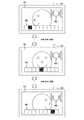
[回転角度に基づく傾き具合メータの表示遷移例]
図15は、本発明の第1の実施の形態におけるグループ画像再生部160により表示される操作支援情報(傾き具合メータ)の表示遷移例を示す図である。この例では、撮像装置100の回転角度に応じて、画送りまたは画戻しを行う場合における表示遷移例を示す。また、この例では、画送りまたは画戻しを行う際の基準角度が20度であり、撮像装置100の傾き角度が20度を超える毎に画送りまたは画戻しを行う例を示す。なお、図15乃至図17に示す例では、傾き具合メータを構成する各矩形上に、対応する角度を表す。[Display transition example of the tilt meter based on the rotation angle]
FIG. 15 is a diagram illustrating a display transition example of the operation support information (tilt degree meter) displayed by the group
図15(a)には、ユーザにより右側方向に傾けられた場合における撮像装置100の遷移を示す。図15(b)には、ユーザにより撮像装置100が右側方向に傾けられた場合に、その傾け角度に応じて表示される傾き具合メータの表示遷移を示す。なお、図15(a)および図15(b)は、互いに対応しているが、図15(b)の一部は省略して示す。 FIG. 15A shows a transition of the
例えば、図15(a)の最上部に示す状態611は、撮像装置100が水平面330と同一面に存在する状態であるものとする。この場合には、図15(b)の最上部の状態601に示すように、傾き具合メータの真ん中部分の矩形領域のみが、他の領域と異なる表示態様(例えば、黒色)となっているものとする。なお、以下では、他の領域と異なる表示態様を黒色と称して説明する。 For example, the
例えば、図15(a)に示す状態612および613のように、ユーザが撮像装置100を持った状態で右側方向に回転をさせていく場合を想定する。この場合に、撮像装置100の右側方向への回転角度θが5度に達した場合には、図15(b)の状態602に示すように、傾き具合メータの真ん中から右側部分の2つの矩形領域が黒くなるが、画送りは行われない。さらに、ユーザが撮像装置100を持った状態で、右側方向に回転をさせていくと、回転角度θに応じて、傾き具体メータの真ん中から右側部分の矩形領域が順次黒くなっていく。具体的には、回転角度θが10度に達した場合には、傾き具体メータの真ん中から右側部分の2つの矩形領域が黒くなり(状態603)、回転角度θが15度に達した場合には、傾き具体メータの真ん中から右側部分の3つの矩形領域が黒くなる(状態604)。ただし、状態601乃至604の場合には、画送りは行われない。 For example, as in
続いて、撮像装置100の右側方向への回転角度θが20度に達した場合には、状態605に示すように、傾き具体メータの真ん中から右側部分が全て黒くなり、画送りの傾きに達した旨を表示するとともに、画送りが行われる。 Subsequently, when the rotation angle θ in the right direction of the
このように画送りが行われ、次の画像が入出力パネル101に表示された後には、状態606に示すように、傾き具体メータの真ん中部分の矩形領域のみが黒くなる。すなわち、状態606における傾き具体メータは、撮像装置100が水平面330と同一面に存在する状態(状態601)と同じとなる。 After the image is fed in this way and the next image is displayed on the input /
同様に、ユーザが撮像装置100を持った状態で、右側方向に回転をさせていくと、回転角度θに応じて、図15(b)の状態607および608に示すように、傾き具体メータにおける矩形領域が黒くなるように表示される。 Similarly, when the user rotates in the right direction while holding the
ここで、表示対象画像のうち、最後の画像を画送りする角度まで、右側方向への回転が行われた場合には、傾き具体メータが状態605と同じ状態となる。これにより、これ以上の右側方向への回転が行われた場合でも、画送りが行われない旨を通知することができる。 Here, in the case where the rightward rotation is performed up to the angle at which the last image is displayed among the display target images, the inclination specific meter is in the same state as the
また、撮像装置100が左側方向に回転された場合についても同様に、傾き具合メータの真ん中から左側部分の矩形領域が順次黒くなる。 Similarly, when the
以上では、基準角度(例えば、20度)を超える毎に、画送りまたは画戻しを行う例を示したが、他の操作方法により画送りまたは画戻しを行うことができる。そこで、以下では、他の操作方法により画送りまたは画戻しを行う例を示す。 In the above, an example in which image feeding or image returning is performed every time a reference angle (for example, 20 degrees) is exceeded has been described, but image feeding or image returning can be performed by other operation methods. Therefore, in the following, an example in which image forwarding or image returning is performed by another operation method will be described.
図16は、本発明の第1の実施の形態におけるグループ画像再生部160により表示される操作支援情報(傾き具合メータ)の表示遷移例を示す図である。この例では、撮像装置100の回転角度が一定角度に達した後にその状態が維持されている場合に、画送り画戻しを順次行う場合における表示遷移例を示す。また、この例では、画送りまたは画戻しを行う際の基準角度が20度であり、撮像装置100の傾き角度が20度を維持している期間、画送りを順次行う例を示す。なお、図16および図17では、図15(a)に示す撮像装置100の遷移例を省略する。 FIG. 16 is a diagram illustrating a display transition example of the operation support information (tilt degree meter) displayed by the group
図16(a)には、ユーザにより撮像装置100が右側方向に傾けられた場合に、その傾け角度に応じて表示される傾き具合メータの表示遷移を示す。なお、図16(a)に示す状態621乃至625は、図15(b)に示す状態601乃至605に対応する。すなわち、図15(a)に示す撮像装置100の状態612および613のように、ユーザが撮像装置100を持った状態で右側方向に回転をさせていく場合には、図15(b)に示す状態601乃至604と同様となる。また、状態621乃至624の場合には、画送りは行われない。 FIG. 16A shows the display transition of the tilt condition meter displayed according to the tilt angle when the
続いて、撮像装置100の右側方向への回転角度θが20度に達した場合には、状態625に示すように、傾き具体メータの真ん中から右側部分が全て黒くなり、画送りの傾きに達した旨を表示するとともに、画送りが行われる。 Subsequently, when the rotation angle θ in the right direction of the
図16(b)には、撮像装置100の右側方向への回転角度θが20度に達した後に、回転角度θが維持された場合(または回転角度θ以上の状態が維持された場合)における傾き具合メータの表示例を示す。 FIG. 16B shows a case where the rotation angle θ is maintained after the rotation angle θ in the right direction of the
このように撮像装置100の右側方向への回転角度θが20度に達した後に、回転角度θが維持された場合には画送りが行われ、次の画像が入出力パネル101に表示された後には状態626となる。この状態626は、状態625が維持されている状態である。すなわち、状態626における傾き具体メータは、撮像装置100の右側方向への回転角度θが20度に達した状態(状態625)と同じとなる。また、回転角度θが維持されている状態では、一定間隔で画送りが行われる。 As described above, when the rotation angle θ in the right direction of the
図16(c)には、撮像装置100の右側方向への回転角度θが20度に達した後に、回転角度θが戻された場合における傾き具合メータの表示例を示す。 FIG. 16C shows a display example of the tilt condition meter when the rotation angle θ is returned after the rotation angle θ in the right direction of the
このように撮像装置100の右側方向への回転角度θが20度に達した後に、回転角度θが戻された場合(すなわち、回転角度θが20度未満となった場合)には、画送りが行われ、次の画像が入出力パネル101に表示された後には状態627となる。すなわち、撮像装置100の右側方向への回転角度θが20度に達した後に、回転角度θが戻された場合には、その戻された角度に応じて、傾き具合メータの表示を戻し、画送りを停止させる。 As described above, when the rotation angle θ is returned after the rotation angle θ in the right direction of the
また、撮像装置100が左側方向に回転された場合についても同様に、傾き具合メータの真ん中から左側部分の矩形領域が順次黒くなる。 Similarly, when the
以上では、撮像装置100の回転角度が、画送りまたは画戻しの基準角度を超えるか否かに応じて、画送りまたは画戻しを行う例を示した。ただし、例えば、撮像装置100の回転角速度が、基準を超えるか否かに応じて、画送りまたは画戻しを行うようにしてもよい。そこで、以下では、撮像装置100の回転角速度が、基準を超えるか否かに応じて、画送りまたは画戻しを行う例について説明する。 In the above, an example in which image feeding or image returning is performed according to whether the rotation angle of the
[回転角速度に基づく傾き具合メータの表示遷移例]
図17は、本発明の第1の実施の形態におけるグループ画像再生部160により表示される操作支援情報(傾き具合メータ)の表示遷移例を示す図である。この例では、撮像装置100の回転角速度(回転角度/秒)に応じて、画送りまたは画戻しを行う場合における表示遷移例を示す。すなわち、この例では、一度の回転操作により、一定の角速度に達したか否かに応じて、画送りまたは画戻しを行う例を示す。また、この例では、画送りまたは画戻しを行う際の回転角速度(回転角度/秒)が20度/秒であり、撮像装置100の回転角速度が20度/秒を超える毎に画送りまたは画戻しを行う例を示す。[Example of display transition of tilt meter based on rotational angular velocity]
FIG. 17 is a diagram illustrating a display transition example of the operation support information (tilt condition meter) displayed by the group
図17(a)には、ユーザにより撮像装置100が右側方向に5度/秒で回転された場合に、その回転角速度に応じて表示される傾き具合メータの表示遷移を示す(状態631および632)。この場合には、回転角速度が20度/秒に達しないため、画送りは行われず、元の状態に戻る(すなわち、状態632から状態631に戻る)。 FIG. 17A shows a display transition of the inclination meter displayed according to the rotation angular velocity when the
図17(b)には、ユーザにより撮像装置100が右側方向に10度/秒で回転された場合に、その回転角速度に応じて表示される傾き具合メータの表示遷移を示す(状態633および634)。この場合には、回転角速度が20度/秒に達しないため、画送りは行われず、元の状態に戻る(すなわち、状態634から状態633に戻る)。なお、ユーザにより撮像装置100が右側方向に15度/秒で回転された場合についても同様に、その傾け角速度に応じて傾き具合メータの表示状態が変化するが、回転角速度が20度/秒に達しないため、画送りは行われない。この場合も同様に元の状態に戻る。 FIG. 17B shows a display transition of the tilt meter displayed in accordance with the rotation angular velocity when the
図17(c)には、ユーザにより撮像装置100が右側方向に20度/秒で回転された場合に、その回転角速度に応じて表示される傾き具合メータの表示遷移を示す。この場合には、回転角速度が20度/秒に達したため、画送りが行われる。この画送りの後に、その角度の状態が維持されている場合(すなわち、0度/秒の場合)には、元の状態に戻る(すなわち、状態636から状態637に戻る)。また、その回転角速度が維持されている場合(またはその回転角速度以上の状態が維持された場合)には、その維持されている期間に応じて、傾き具合メータの表示状態が維持され、画送りが順次行われる。 FIG. 17C shows the display transition of the tilt condition meter displayed in accordance with the rotation angular velocity when the
なお、図17(b)および(c)では、状態633から状態634への表示遷移、および、状態635から状態636への表示遷移の一部を省略して示す。 In FIGS. 17B and 17C, a part of display transition from the
また、撮像装置100が左側方向に回転された場合についても同様に、傾き具合メータの真ん中から左側部分の矩形領域が順次黒くなる。 Similarly, when the
[操作支援情報の表示例]
図18および図19は、本発明の第1の実施の形態における入出力パネル101における表示遷移と、撮像装置100の姿勢との関係を概略的に示す図である。[Display example of operation support information]
18 and 19 are diagrams schematically showing a relationship between display transitions in the input /
図18には、表示対象画像に操作支援情報(インジケータ)を重ねて入出力パネル101に表示させる場合における遷移例を示す。また、図19には、表示対象画像に操作支援情報(傾け具合メータ)を重ねて入出力パネル101に表示させる場合における遷移例を示す。また、図18(b)および図19(b)には、入出力パネル101における画像が表示される際における撮像装置100の姿勢の遷移例を示す。なお、図18(b)および図19(b)に示す例では、グループ画像表示モードの設定時における撮像装置100の姿勢が、水平面330と同一面に位置する場合における遷移例を示す。また、図18および図19では、各図(a)に示す入出力パネル101に表示される画像と、各図(b)に示す撮像装置100の姿勢とについて、対応する関係を左右に並べて示す。 FIG. 18 shows a transition example in the case where the operation support information (indicator) is displayed on the input /
図18(a)および図19(a)には、入出力パネル101に表示される画像の遷移を示す。なお、図18(a)および図19(a)に示す入出力パネル101に表示される画像651乃至653は、同一人物の顔について異なる視点から撮像された画像である。このため、撮像装置100を左右に傾けるユーザ操作を早く行い、画送りまたは画戻しを早く行うことにより、3次元の物体(人物の顔)を見ているようにユーザに認識させることができる。すなわち、撮像装置100を左右に傾けるユーザ操作により、擬似的に3次元画像を見ているようにユーザに認識させることができる。また、画像651乃至653が属するグループは、7つの画像(画像651乃至653を含む)により構成されているものとする。なお、画像651は、そのグループの代表画像であるものとし、画像652および653は、表示順序において最初と最後の画像であるものとする。 FIG. 18A and FIG. 19A show transitions of images displayed on the input /
最初に、図18を参照して、表示対象画像に操作支援情報(インジケータ)を重ねて入出力パネル101に表示させる場合について説明する。なお、上述したように、グループ画像表示モードが設定された直後には、代表画像(画像651)が入出力パネル101に表示される。この場合には、図7(c)と同様に、操作支援情報403が画像651に重ねて表示される。ただし、この操作支援情報403については、ユーザ操作により画送りまたは画戻りが一定時間(または、一定回数)行われた場合に消去または縮小されるため、図18(a)および図19(b)では、その表示例を省略する。 First, a case where operation support information (indicator) is superimposed on a display target image and displayed on the input /
ここで、グループ画像表示モードが設定されている場合において、画像652が入出力パネル101に表示されている場合を想定する。この場合には、画像652が、同一グループを構成する7つの画像のうち、表示順序において最初の画像であるため、インジケータ660における左端の矩形領域が、他の矩形領域と異なる表示態様とされる。この場合には、それ以上の画戻しを行うことができない。 Here, it is assumed that the
また、グループ画像表示モードが設定されている場合において、画像653が入出力パネル101に表示されている場合を想定する。この場合には、画像653が、同一グループを構成する7つの画像のうち、表示順序において最後の画像であるため、インジケータ660における右端の矩形領域が、他の矩形領域と異なる表示態様とされる。この場合には、それ以上の画送りを行うことができない。 Further, it is assumed that the
このように、複数の画像の全体における、入出力パネル101に表示されている画像に関する順序(例えば、正規化角度情報により特定される順序)を表す標識をインジケータとして表示させることができる。 As described above, a sign indicating the order of the images displayed on the input / output panel 101 (for example, the order specified by the normalized angle information) in the whole of the plurality of images can be displayed as an indicator.
また、グループ画像表示モードが設定されている場合において、表示対象画像とともにインジケータ660を表示させることにより、そのグループにおける表示対象画像の表示順序における位置を容易に把握することができる。これにより、画送りまたは画戻し操作を行う場合には、表示対象画像を見ながら、その操作を容易に行うことができる。 In addition, when the group image display mode is set, by displaying the
次に、図19を参照して、表示対象画像に操作支援情報(傾き具合メータ)を重ねて入出力パネル101に表示させる場合について説明する。 Next, with reference to FIG. 19, a description will be given of a case where the operation support information (tilt degree meter) is displayed on the input /
ここで、グループ画像表示モードが設定されている場合において、画像652が入出力パネル101に表示されている場合を想定する。この場合には、画像652が、同一グループを構成する7つの画像のうち、表示順序において最初の画像であるため、傾き具合メータ670における真ん中から左端までの矩形領域が、他の矩形領域と異なる表示態様とされる。この場合には、それ以上の画戻しを行うことができない。 Here, it is assumed that the
また、グループ画像表示モードが設定されている場合において、画像653が入出力パネル101に表示されている場合を想定する。この場合には、画像653が、同一グループを構成する7つの画像のうち、表示順序において最後の画像であるため、傾き具合メータ670における真ん中から右端までの矩形領域が、他の矩形領域と異なる表示態様とされる。この場合には、それ以上の画送りを行うことができない。 Further, it is assumed that the
このように、入出力パネル101における表示状態を変更するために必要な撮像装置100の姿勢の変化量を表す標識を傾き具合メータとして表示させることができる。すなわち、複数の画像について画送りまたは画戻しを行うために必要な撮像装置100の姿勢の変化量を表す標識を傾き具合メータとして表示させることができる。 In this way, a sign indicating the amount of change in the posture of the
なお、撮像装置100の傾き角度に応じた傾き具合メータ670の表示状態の遷移については、図15乃至図17の遷移例と同様であるため、ここでの説明を省略する。 Note that the transition of the display state of the
このように、グループ画像表示モードが設定されている場合において、表示対象画像とともに傾き具合メータ670を表示させることにより、各表示対象画像を表示させる際における傾き具合をユーザが容易に把握することができる。また、そのグループにおける表示対象画像の表示順序における位置を容易に把握することができる。これにより、画送りまたは画戻し操作を行う場合には、表示対象画像を見ながら、その操作を容易に行うことができる。 As described above, when the group image display mode is set, by displaying the
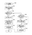
[撮像装置の動作例]
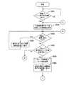
図20および図21は、本発明の第1の実施の形態における撮像装置100による画像コンテンツ再生処理の処理手順の一例を示すフローチャートである。[Operation example of imaging device]
20 and 21 are flowcharts illustrating an example of a processing procedure of image content reproduction processing by the
最初に、画像コンテンツの表示指示操作が行われたか否かが判断され(ステップS901)、その表示指示操作が行われていない場合には監視を継続して行う。一方、その表示指示操作が行われた場合には(ステップS901)、制御部140が代表画像表示モードを設定し、代表画像再生部150が、代表画像およびグループ化されていない画像を表示部111に表示させる(ステップS902)。 First, it is determined whether or not an image content display instruction operation has been performed (step S901). If the display instruction operation has not been performed, monitoring is continued. On the other hand, when the display instruction operation is performed (step S901), the
続いて、代表画像表示モードが設定されている状態で、画送り操作または画戻し操作が行われたか否かが判断される(ステップS903)。画送り操作または画戻し操作が行われた場合には(ステップS903)、代表画像再生部150が表示部111に表示されている画像の表示切替を行う(ステップS904)。すなわち、表示部111に表示されている画像の画送りまたは画戻しが行われる。 Subsequently, it is determined whether an image forwarding operation or an image returning operation has been performed in a state where the representative image display mode is set (step S903). When the image forwarding operation or the image returning operation is performed (step S903), the representative
また、画送り操作または画戻し操作が行われていない場合には(ステップS903)、グループ画像表示モードの設定操作が行われたか否かが判断され(ステップS905)、グループ画像表示モードの設定操作が行われていない場合には、ステップS916に進む。一方、グループ画像表示モードの設定操作が行われた場合には(ステップS905)、グループ画像表示モード設定処理が行われる(ステップS920)。このグループ画像表示モード設定処理については、図22を参照して詳細に説明する。 If no image forwarding operation or image returning operation has been performed (step S903), it is determined whether or not a group image display mode setting operation has been performed (step S905), and a group image display mode setting operation is performed. If not, the process proceeds to step S916. On the other hand, when a group image display mode setting operation has been performed (step S905), group image display mode setting processing is performed (step S920). The group image display mode setting process will be described in detail with reference to FIG.
続いて、グループ画像再生部160が、最初の操作支援情報(例えば、図7(c)に示す操作支援情報403)を表示対象画像に重ねて表示部111に表示させる(ステップS906)。すなわち、グループ画像再生部160が、画像コンテンツ記憶部200から取得された画像コンテンツをデコードし、このデコードされた画像コンテンツに基づいて表示用の画像を描画メモリ170に描画する。そして、グループ画像再生部160が、描画メモリ170に描画された画像のうちの1つ(代表画像)と、最初の操作支援情報とを同時に表示部111に表示させる。 Subsequently, the group
続いて、最初の操作支援情報が表示されているか否かが判断され(ステップS907)、最初の操作支援情報が表示されていない場合には、ステップS910に進む。一方、最初の操作支援情報が表示されている場合には(ステップS907)、グループ画像表示モードが設定されてから一定時間が経過したか否かが判断される(ステップS908)。グループ画像表示モードが設定されてから一定時間が経過した場合には(ステップS908)、グループ画像再生部160が、表示部111に表示されていた最初の操作支援情報を消去させる(ステップS909)。一方、グループ画像表示モードが設定されてから一定時間が経過していない場合には(ステップS908)、ユーザによる傾け操作があったか否かが判断される(ステップS910)。すなわち、グループ画像再生部160が、解析部130から出力された解析情報に基づいて、撮像装置100の姿勢が一定以上変化したか否かを判断する。 Subsequently, it is determined whether or not the first operation support information is displayed (step S907). If the first operation support information is not displayed, the process proceeds to step S910. On the other hand, when the first operation support information is displayed (step S907), it is determined whether or not a certain time has elapsed since the group image display mode was set (step S908). When a certain time has elapsed since the group image display mode was set (step S908), the group
ユーザによる傾け操作があった場合には(ステップS910)、最初の操作支援情報が表示されているか否かが判断され(ステップS911)、最初の操作支援情報が表示されていない場合には、ステップS913に進む。一方、最初の操作支援情報が表示されている場合には(ステップS911)、グループ画像再生部160が、表示部111に表示されていた最初の操作支援情報を消去させる(ステップS912)。 When the tilt operation is performed by the user (step S910), it is determined whether or not the first operation support information is displayed (step S911), and when the first operation support information is not displayed, the step is performed. The process proceeds to S913. On the other hand, when the first operation support information is displayed (step S911), the group
続いて、グループ画像再生部160が、ユーザによる傾け操作に応じた操作量および表示画像(表示部111に表示されている画像)に基づいて、操作支援情報(インジケータまたは傾け具合メータ)の表示状態を変更する(ステップS913)。続いて、グループ画像再生部160が、ユーザによる傾け操作に応じた操作量が表示切替の基準を超えている場合には、表示部111に表示される画像の表示切替(画送りまたは画戻し)を行い(ステップS914)、ステップS907に戻る。なお、ユーザによる傾け操作に応じた操作量が表示切替の基準を超えていない場合には、表示部111に表示される画像の表示切替(画送りまたは画戻し)を行わずに、ステップS907に戻る。 Subsequently, the group
また、ユーザによる傾け操作がない場合には(ステップS910)、代表画像表示モードの設定操作が行われたか否かが判断され(ステップS915)、その設定操作が行われた場合には、ステップS902に戻る。一方、代表画像表示モードの設定操作が行われていない場合には(ステップS915)、画像コンテンツの表示終了操作が行われたか否かが判断され(ステップS916)、その表示終了操作が行われた場合には、画像コンテンツ再生処理の動作を終了する。また、画像コンテンツの表示終了操作が行われていない場合には(ステップS916)、グループ画像表示モードが設定されているか否かが判断される(ステップS917)。そして、グループ画像表示モードが設定されている場合には(ステップS917)、ステップS907に戻り、グループ画像表示モードが設定されていない場合(すなわち、代表画像表示モードが設定されている場合)には、ステップS903に戻る。If there is no tilt operation by the user (step S910), it is determined whether or not a representative image display mode setting operation has been performed (step S915). If the setting operation has been performed, step S902 is performed. Return to. On the other hand, when the representative image display mode setting operation has not been performed (step S915), it is determined whether or not the image content display end operation has been performed (step S916), and the display end operation has been performed. In this case, the operation of the image content reproduction process is terminated. If the image content display end operation has not been performed (step S916), it is determined whether the group image display mode is set (step S917). When the group image display mode is set (step S917), the process returns to step S907, and when the group image display mode is not set (that is, when the representative image display mode is set). Return to step S903.
図22は、本発明の第1の実施の形態における撮像装置100による画像コンテンツ再生処理の処理手順のうちのグループ画像表示モード設定処理(図20に示すステップS920の処理手順)の一例を示すフローチャートである。 FIG. 22 is a flowchart showing an example of the group image display mode setting process (the process procedure of step S920 shown in FIG. 20) in the process procedure of the image content reproduction process by the
最初に、グループ画像再生部160が、グループ画像表示モードの設定操作時に表示部111に表示されていた代表画像に対応するグループに属する各画像コンテンツを画像コンテンツ記憶部200から取得する(ステップS921)。また、グループ画像再生部160が、そのグループに属する各画像コンテンツに関連付けられている画像管理情報を画像管理情報記憶部210から取得する(ステップS921)。 First, the group
続いて、操作方法決定部180が、取得された画像管理情報に角度情報が含まれるか否かを判断する(ステップS922)。そして、取得された画像管理情報に角度情報が含まれている場合には(ステップS922)、操作方法決定部180が、取得された画像管理情報に含まれる角度情報を画像コンテンツ毎に正規化する(ステップS923)。 Subsequently, the operation
続いて、操作方法決定部180が、正規化された角度情報(正規化角度情報)に基づいて、取得された画像コンテンツと、傾け角度(基準角度)とを関連付ける(ステップS924)。この場合に、取得された画像コンテンツの数が傾け角度(基準角度)の数よりも大きい場合には、操作方法決定部180が、傾け角度(基準角度)の数の範囲内となるように、取得された画像コンテンツについて間引き処理を行う。続いて、操作方法決定部180が、その関連付けによる対応関係に基づいて、インジケータの表示領域を算出する(ステップS925)。 Subsequently, the operation
また、取得された画像管理情報に角度情報が含まれていない場合には(ステップS922)、操作方法決定部180が、取得された画像コンテンツの数が、表示可能数(傾け角度(基準角度)の数)よりも大きいか否かを判断する(ステップS926)。取得された画像コンテンツの数が表示可能数以下である場合には(ステップS926)、ステップS928に進む。一方、取得された画像コンテンツの数が表示可能数よりも大きい場合には(ステップS926)、操作方法決定部180が、表示可能数の範囲内となるように、取得された画像コンテンツについて間引き処理を行う(ステップS927)。 If the acquired image management information does not include angle information (step S922), the operation
続いて、操作方法決定部180が、取得された画像コンテンツ(または間引き処理後の画像コンテンツ)と、傾け角度(基準角度)とを関連付ける(ステップS928)。続いて、操作方法決定部180が、その関連付けによる対応関係に基づいて、インジケータの表示領域を算出する(ステップS929)。 Subsequently, the operation
<2.変形例>
以上では、操作支援情報として、棒状の矩形により構成される操作支援情報(傾き具合メータまたはインジケータ)を表示する例を示した。この変形例では、他の構成により表示される操作支援情報(傾き具合メータまたはインジケータ)の例を示す。なお、撮像装置100の構成等については、操作支援情報の表示態様が異なる点以外は、本発明の第1の実施の形態と同様である。このため、以下では、本発明の第1の実施の形態と異なる点を中心にして説明し、共通する部分の説明の一部を省略する。<2. Modification>
In the above, the example which displays the operation assistance information (tilt condition meter or indicator) comprised by the rod-shaped rectangle as operation assistance information was shown. In this modified example, an example of operation support information (tilt condition meter or indicator) displayed by another configuration is shown. The configuration of the
[傾き具体メータの表示例]
図23は、本発明の第1の実施の形態の変形例におけるグループ画像再生部160により表示される操作支援情報(傾き具合メータ)と、入出力パネル101における表示遷移例とを示す図である。[Example of tilt meter display]
FIG. 23 is a diagram showing operation support information (tilt condition meter) displayed by the group
図23(a)には、円形状により構成される操作支援情報(傾き具合メータ)の一例を示す。この傾き具合メータを構成する円の外側には、対応する角度を表す。また、撮像装置100の傾き角度については、傾き具合メータを構成する円の中心から、その傾き角度に対応する円上の位置までの矢印により表すものとする。 FIG. 23A shows an example of operation support information (tilt condition meter) configured in a circular shape. A corresponding angle is represented on the outside of the circle constituting the inclination meter. Further, the tilt angle of the
図23(b)には、入出力パネル101に表示される画像の遷移を示す。上述したように、グループ画像表示モードが設定された直後には、代表画像(画像701)が入出力パネル101に表示される。この場合には、図7(c)と同様に、操作支援情報711が画像701に重ねて表示される。ただし、操作支援情報711については、ユーザ操作により画送りまたは画戻りが一定時間(または、一定回数)行われた場合に消去または縮小される。 FIG. 23B shows transition of images displayed on the input /
また、図23(b)に示す例では、撮像装置100の回転角度に応じて、画送りまたは画戻しを行う場合における表示遷移例を示す。また、この例では、画送りまたは画戻しを行う際の基準角度が30度であり、撮像装置100の傾き角度が30度を超える毎に画送りまたは画戻しを行う例を示す。 In addition, the example illustrated in FIG. 23B illustrates a display transition example in a case where image forwarding or image returning is performed according to the rotation angle of the
例えば、ユーザが撮像装置100を持った状態で左側方向に回転をさせていく場合を想定する。例えば、撮像装置100の左側方向への回転角度が20度に達した場合には、傾き具合メータを構成する円の中心から、その回転角度(20度)に対応する円上の位置までの矢印が付された傾き具合メータ712が画像701に表示される。ただし、この場合には、画送りは行われない。さらに、ユーザが撮像装置100を持った状態で左側方向に回転をさせていき、その回転角度が30度に達した場合を想定する。この場合には、傾き具合メータを構成する円の中心から、その回転角度(30度)に対応する円上の位置(円の最下部)までの矢印が付された傾き具合メータが画像701に表示され、画送りの傾きに達した旨を表示するとともに、画送りが行われる。 For example, it is assumed that the user rotates the
また、撮像装置100が右側方向に回転された場合についても同様に、傾き具合メータを構成する円の中心から、その回転角度に対応する円上の位置までの矢印が付された傾き具合メータ713が画像701に重ねて表示される。 Similarly, when the
図24は、本発明の第1の実施の形態の変形例におけるグループ画像再生部160により表示される操作支援情報(傾き具合メータ)と、入出力パネル101における表示遷移例とを示す図である。 FIG. 24 is a diagram showing operation support information (tilt condition meter) displayed by the group
図24(a)には、円形状により構成される操作支援情報(傾き具合メータ)の一例を示す。この傾き具合メータを構成する円の外側には、対応する回転角速度を表す。また、撮像装置100の回転角速度については、傾き具合メータを構成する円の中心から、その回転角速度に対応する円上の位置までの矢印により表すものとする。 FIG. 24A shows an example of operation support information (tilt condition meter) configured in a circular shape. On the outside of the circle constituting this inclination meter, the corresponding rotational angular velocity is represented. Further, the rotational angular velocity of the
図24(b)には、入出力パネル101に表示される画像の遷移を示す。なお、代表画像(画像701)が入出力パネル101に表示され、操作支援情報711が画像701に重ねて表示される点は、図23(b)に示す例と同様である。 FIG. 24B shows the transition of images displayed on the input /
また、図24(b)に示す例では、撮像装置100の回転角速度に応じて、画送りまたは画戻しを行う場合における表示遷移例を示す。また、この例では、画送りまたは画戻しを行う際の回転角速度(回転角度/秒)が20度/秒であり、撮像装置100の回転角速度が20度/秒を超える毎に画送りまたは画戻しを行う例を示す。 In addition, the example illustrated in FIG. 24B illustrates a display transition example in a case where image forwarding or image returning is performed according to the rotation angular velocity of the
例えば、ユーザが撮像装置100を持った状態で左側方向に回転をさせ、その回転角速度が20度/秒に達した場合を想定する。この場合には、傾き具合メータを構成する円の中心から、その回転角速度(20度/秒)に対応する円上の位置までの矢印が付された傾き具合メータ721が画像701に表示され、画送りの回転角速度に達した旨を表示するとともに、画送りが行われる。この画送りにより画像702が表示される。また、この画送りの後に、その角度の状態が維持されている場合(すなわち、0度/秒の場合)には、元の状態に戻る。すなわち、傾き具合メータを構成する円の中心から、その回転角速度(0度/秒)に対応する円上の位置(円の最上部)までの矢印が付された傾き具合メータ722が画像702に表示される。 For example, it is assumed that the user rotates leftward with the
また、撮像装置100が右側方向に回転された場合についても同様に、傾き具合メータを構成する円の中心から、その回転角速度に対応する円上の位置までの矢印が付された傾き具合メータが表示される。 Similarly, when the
なお、図23および図24に示す傾き具合メータにおいて、円の最上部と、矢印が指し示す円上の位置との範囲(その2点と、円の中心とにより特定される扇系の範囲)を、他の領域と異なる表示態様として、ユーザが認識し易くなるようにしてもよい。 23 and 24, the range of the uppermost part of the circle and the position on the circle indicated by the arrow (the range of the fan system specified by the two points and the center of the circle) As a display mode different from other regions, the user may easily recognize.
[インジケータの表示例]
図25乃至図28は、本発明の第1の実施の形態の変形例における入出力パネル101における表示遷移例を示す図である。これらの例では、グループ画像再生部160により表示される操作支援情報(インジケータ)の表示態様を変形した例を示す。また、図25および図27では、表示対象となるグループの種類を示す表示支援情報(例えば、アイコン)802および812をインジケータとともに表示する例を示す。[Example of indicator display]
25 to 28 are diagrams showing examples of display transition in the input /
図25および図26には、多視点画像を表示する場合における表示遷移例を示す。図25には、インジケータ801と、表示対象となるグループの種類が「多視点画像」である旨を示す表示支援情報802とを同時に表示する例を示す。図26には、表示対象となるグループの種類が「多視点画像」である旨を示すインジケータ811を表示する例を示す。 25 and 26 show display transition examples in the case of displaying a multi-viewpoint image. FIG. 25 shows an example in which an
図27および図28には、連写画像を表示する場合における表示遷移例を示す。図27には、インジケータ821と、表示対象となるグループの種類が「連写画像」である旨を示す表示支援情報822とを同時に表示する例を示す。図28には、表示対象となるグループの種類が「連写画像」である旨を示すインジケータ831を表示する例を示す。 FIG. 27 and FIG. 28 show display transition examples in the case of displaying continuous shot images. FIG. 27 shows an example in which an
なお、図25乃至図28に示すインジケータにおける表示状態については、図18等に示す例と同様であるため、ここでの説明を省略する。 Note that the display states of the indicators shown in FIGS. 25 to 28 are the same as the example shown in FIG.
このように、入出力パネル101に表示されている画像に係る画像群を構成する各画像の相関性(例えば、グループ種類に対応する)に基づいて、インジケータの表示態様が画像群毎に変更して表示される。 As described above, the display mode of the indicator is changed for each image group based on the correlation (for example, corresponding to the group type) of each image constituting the image group related to the image displayed on the input /
また、グループ画像表示モードが設定されている場合において、表示対象画像とともに、表示対象となるグループの種類を示す表示支援情報を表示させることにより、各表示対象画像を表示させる際における操作をユーザが容易に行うことができる。すなわち、画送りまたは画戻し操作を行う場合には、表示対象画像を見ながら、その操作を容易に行うことができる。 When the group image display mode is set, the display support information indicating the type of the group to be displayed is displayed together with the display target image, so that the user can perform an operation when displaying each display target image. It can be done easily. That is, when performing an image forwarding or image returning operation, the operation can be easily performed while viewing the display target image.
以上で示したように、本発明の実施の形態では、グループ画像表示モードの設定時には、最初の操作支援情報(例えば、図7(c)に示す操作支援情報403)を表示する。これにより、例えば、撮像装置100の持ち方が悪く、画像の閲覧を開始した途端に、表示されている視点の切り替えが発生して見たい視点の画像を見逃してしまうことを防止することができる。 As described above, in the embodiment of the present invention, when the group image display mode is set, the first operation support information (for example,
また、例えば、グループ画像表示モードの設定時に多視点画像を表示している場合には、傾き具合メータを表示させることにより、どのくらい傾けると視点が切り替わるのかをユーザが容易に把握することができる。また、例えば、切り替える視点の変化が少ない画像を表示している場合でも、ユーザが傾けるという操作をして画像が切り替わったことをユーザが容易に把握することができる。 Further, for example, when a multi-viewpoint image is displayed when the group image display mode is set, the user can easily grasp how much the viewpoint switches when tilted by displaying the tilt meter. Further, for example, even when an image with a small change in viewpoint to be switched is displayed, the user can easily grasp that the image has been switched by performing an operation of tilting the user.
また、例えば、グループ画像表示モードの設定時に多視点画像を表示している場合には、インジケータを表示させることにより、現在表示している視点が、全視点の中でどこの視点になるのかをユーザが容易に把握することができる。また、例えば、最も右から撮影した視点の画像を表示している場合には、それ以上右側を下にして傾けても視点が切り替わらないことをユーザが容易に把握することができる。 Also, for example, when a multi-viewpoint image is displayed when the group image display mode is set, by displaying an indicator, the user can determine which viewpoint is the currently displayed viewpoint among all viewpoints. Can be easily grasped. Further, for example, when an image of the viewpoint taken from the rightmost is displayed, the user can easily grasp that the viewpoint does not change even if the image is tilted with the right side down.
なお、以上で示した例では、撮像装置100の上下方向を軸とする回転により入出力パネル101における表示状態を変更する例を示した。ただし、撮像装置100の左右方向を軸とする回転により入出力パネル101における表示状態を変更する場合についても本発明の実施の形態を適用することができる。この場合には、例えば、上下の傾け操作により画像の変更を行い、インジケータや傾け具合メータも縦長に配置して表示することができる。さらに、例えば、上下左右の両方向に視点がある画像を表示させる場合には、上下左右の両方向への傾け操作により視点切り替えを行い、インジケータや傾け具合メータも上下左右の両方向のものを表示することができる。また、撮像装置100の上下左右、前後方向の何れかの方向へのスライド(平行移動)により入出力パネル101における表示状態を変更する場合についても本発明の実施の形態を適用することができる。 In the example described above, an example in which the display state of the input /
なお、本発明の実施の形態では、撮像装置を例にして説明したが、記録媒体に記憶されている画像コンテンツを表示部に表示させることが可能な画像処理装置に本発明の実施の形態を適用することができる。例えば、撮像機能付き携帯電話機、ナビゲーションシステム、携帯型メディアプレイヤー等の画像処理装置に本発明の実施の形態を適用することができる。 In the embodiment of the present invention, the imaging apparatus has been described as an example. However, the embodiment of the present invention is applied to an image processing apparatus capable of displaying the image content stored in the recording medium on the display unit. Can be applied. For example, the embodiment of the present invention can be applied to an image processing apparatus such as a mobile phone with an imaging function, a navigation system, and a portable media player.
なお、本発明の実施の形態は本発明を具現化するための一例を示したものであり、本発明の実施の形態において明示したように、本発明の実施の形態における事項と、特許請求の範囲における発明特定事項とはそれぞれ対応関係を有する。同様に、特許請求の範囲における発明特定事項と、これと同一名称を付した本発明の実施の形態における事項とはそれぞれ対応関係を有する。ただし、本発明は実施の形態に限定されるものではなく、本発明の要旨を逸脱しない範囲において実施の形態に種々の変形を施すことにより具現化することができる。 The embodiment of the present invention shows an example for embodying the present invention. As clearly shown in the embodiment of the present invention, the matters in the embodiment of the present invention and the claims Each invention-specific matter in the scope has a corresponding relationship. Similarly, the matters specifying the invention in the claims and the matters in the embodiment of the present invention having the same names as the claims have a corresponding relationship. However, the present invention is not limited to the embodiments, and can be embodied by making various modifications to the embodiments without departing from the gist of the present invention.
また、本発明の実施の形態において説明した処理手順は、これら一連の手順を有する方法として捉えてもよく、また、これら一連の手順をコンピュータに実行させるためのプログラム乃至そのプログラムを記憶する記録媒体として捉えてもよい。この記録媒体として、例えば、CD(Compact Disc)、MD(MiniDisc)、DVD(Digital Versatile Disk)、メモリカード、ブルーレイディスク(Blu-ray Disc(登録商標))等を用いることができる。 The processing procedure described in the embodiment of the present invention may be regarded as a method having a series of these procedures, and a program for causing a computer to execute the series of procedures or a recording medium storing the program May be taken as As this recording medium, for example, a CD (Compact Disc), an MD (MiniDisc), a DVD (Digital Versatile Disk), a memory card, a Blu-ray Disc (registered trademark), or the like can be used.
100 撮像装置
101 入出力パネル
102 シャッターボタン
110 入出力部
111 表示部
112 操作受付部
120 姿勢検出部
130 解析部
140 制御部
150 代表画像再生部
160 グループ画像再生部
170 描画メモリ
180 操作方法決定部
200 画像コンテンツ記憶部
210 画像管理情報記憶部DESCRIPTION OF
Claims (24)
Translated fromJapanese画像処理装置の姿勢の変化である傾け角度を検出する検出部と、
前記傾け角度に基づいて複数の画像からなる画像群を構成する各画像を前記表示部に順次表示させるユーザ操作を支援するための情報であって、前記画像群の枚数によって前記姿勢の変化の範囲の中における各傾け角度と前記画像群を構成する各画像との関係が決定されるとともに、前記姿勢の変化の範囲の中における前記検出部で検出された前記傾け角度の位置を示す操作支援情報を、ユーザに提示する提示手段と
を具備する画像処理装置。A display unit;
A detection unit that detects a tilt angle that is a change in the attitude of the image processing device;
Information for supporting a user operation to sequentially display each image constituting an image group composed of a plurality of images based on the tilt angle on the display unit, and the range of change in the posture depending on the number of the image groupsThe operation support information indicating the position of the tilt angle detected by the detection unit within the range of the posture change while determining the relationship betweeneach tilt angle in the image and each image constituting the image group An image processing apparatus comprising: a presenting unit that presents the image to a user.
前記提示手段は、前記姿勢の変化の範囲の中における前記傾け角度の位置を、前記円形状の標識における円周上の位置により表す
請求項1記載の画像処理装置。The operation support information is a circular sign,
The image processing apparatus according to claim 1, wherein the presenting unit represents the position of the tilt angle within the range of the posture change by a position on a circumference of the circular sign.
前記傾け角度に基づいて複数の画像からなる画像群を構成する各画像を前記表示部に順次表示させるユーザ操作を支援するための情報であって、前記画像群の枚数によって前記姿勢の変化の範囲の中における各傾け角度と前記画像群を構成する各画像との関係が決定されるとともに、前記姿勢の変化の範囲の中における前記検出手順で検出された前記傾け角度の位置を示す操作支援情報を、ユーザに提示する提示手順と
を具備する画像処理方法。A detection procedure for detecting a tilt angle, which is a change in posture of an image processing apparatus including a display unit;
Information for supporting a user operation to sequentially display each image constituting an image group composed of a plurality of images based on the tilt angle on the display unit, and the range of change in the posture depending on the number of the image groupsThe operation support information indicating the position of the tilt angle detected by the detectionprocedure in the range of the posture change, while determining the relationship betweeneach tilt angle in the image and each image constituting the image group An image processing method comprising: a presentation procedure for presenting to a user.
前記提示手順は、前記姿勢の変化の範囲の中における前記傾け角度の位置を、前記円形状の標識における円周上の位置により表す
請求項9記載の画像処理方法。The operation support information is a circular sign,
Theimage processing method according to claim 9, wherein in the presenting procedure, the position of the tilt angle in the range of the change in posture is represented by a position on a circumference of the circular sign.
前記傾け角度に基づいて複数の画像からなる画像群を構成する各画像を前記表示部に順次表示させるユーザ操作を支援するための情報であって、前記画像群の枚数によって前記姿勢の変化の範囲の中における各傾け角度と前記画像群を構成する各画像との関係が決定されるとともに、前記姿勢の変化の範囲の中における前記検出手順で検出された前記傾け角度の位置を示す操作支援情報を、ユーザに提示する提示手順と
をコンピュータに実行させるプログラム。A detection procedure for detecting a tilt angle, which is a change in posture of an image processing apparatus including a display unit;
Information for supporting a user operation to sequentially display each image constituting an image group composed of a plurality of images based on the tilt angle on the display unit, and the range of change in the posture depending on the number of the image groupsThe operation support information indicating the position of the tilt angle detected by the detectionprocedure in the range of the posture change, while determining the relationship betweeneach tilt angle in the image and each image constituting the image group A program for causing a computer to execute a presentation procedure for presenting a message to a user.
前記提示手順は、前記姿勢の変化の範囲の中における前記傾け角度の位置を、前記円形状の標識における円周上の位置により表す
請求項17記載のプログラム。The operation support information is a circular sign,
The program according to claim 17, wherein the presentation procedure represents the position of the tilt angle in the range of the posture change by a position on a circumference of the circular sign.
Priority Applications (8)
| Application Number | Priority Date | Filing Date | Title |
|---|---|---|---|
| JP2010063574AJP5754074B2 (en) | 2010-03-19 | 2010-03-19 | Image processing apparatus, image processing method, and program |
| PCT/JP2011/000617WO2011114615A1 (en) | 2010-03-19 | 2011-02-03 | Image processing device, image processing method and program |
| TW100107314ATWI442382B (en) | 2010-03-19 | 2011-03-04 | Image processing device, image processing method and program |
| US13/634,425US9313405B2 (en) | 2010-03-19 | 2011-03-10 | Image processing device, image processing method and program |
| EP11755860.1AEP2548198A4 (en) | 2010-03-19 | 2011-03-10 | Image processing device, image processing method and program |
| PCT/JP2011/001405WO2011114667A1 (en) | 2010-03-19 | 2011-03-10 | Image processing device, image processing method and program |
| CN201180014132.4ACN102804258B (en) | 2010-03-19 | 2011-03-10 | Image processing device, image processing method and program |
| KR1020127023098AKR20130018677A (en) | 2010-03-19 | 2011-03-10 | Image processing device, image processing method and program |
Applications Claiming Priority (1)
| Application Number | Priority Date | Filing Date | Title |
|---|---|---|---|
| JP2010063574AJP5754074B2 (en) | 2010-03-19 | 2010-03-19 | Image processing apparatus, image processing method, and program |
Publications (3)
| Publication Number | Publication Date |
|---|---|
| JP2011197358A JP2011197358A (en) | 2011-10-06 |
| JP2011197358A5 JP2011197358A5 (en) | 2013-04-18 |
| JP5754074B2true JP5754074B2 (en) | 2015-07-22 |
Family
ID=44648731
Family Applications (1)
| Application Number | Title | Priority Date | Filing Date |
|---|---|---|---|
| JP2010063574AExpired - Fee RelatedJP5754074B2 (en) | 2010-03-19 | 2010-03-19 | Image processing apparatus, image processing method, and program |
Country Status (7)
| Country | Link |
|---|---|
| US (1) | US9313405B2 (en) |
| EP (1) | EP2548198A4 (en) |
| JP (1) | JP5754074B2 (en) |
| KR (1) | KR20130018677A (en) |
| CN (1) | CN102804258B (en) |
| TW (1) | TWI442382B (en) |
| WO (2) | WO2011114615A1 (en) |
Families Citing this family (13)
| Publication number | Priority date | Publication date | Assignee | Title |
|---|---|---|---|---|
| US9210414B2 (en)* | 2010-06-30 | 2015-12-08 | Tp Vision Holding B.V. | Multi-view display system and method therefor |
| TWI511526B (en)* | 2012-03-28 | 2015-12-01 | Tpv Display Technology Xiamen | Dimensional display device, image processor and image processing method |
| US9348431B2 (en)* | 2012-07-04 | 2016-05-24 | Korea Advanced Institute Of Science And Technology | Display device for controlling auto-rotation of content and method for controlling auto-rotation of content displayed on display device |
| US9772764B2 (en)* | 2013-06-06 | 2017-09-26 | Microsoft Technology Licensing, Llc | Accommodating sensors and touch in a unified experience |
| US10013737B2 (en) | 2013-09-17 | 2018-07-03 | Nokia Technologies Oy | Determination of an operation |
| JP2015225276A (en)* | 2014-05-29 | 2015-12-14 | セイコーエプソン株式会社 | Display system, display device, display control device, display method and program |
| US10726593B2 (en)* | 2015-09-22 | 2020-07-28 | Fyusion, Inc. | Artificially rendering images using viewpoint interpolation and extrapolation |
| US9762791B2 (en)* | 2014-11-07 | 2017-09-12 | Intel Corporation | Production of face images having preferred perspective angles |
| JP2016206405A (en)* | 2015-04-22 | 2016-12-08 | 株式会社ドリコム | Image display control program, image display control method, and image display apparatus |
| JP2017021461A (en)* | 2015-07-08 | 2017-01-26 | 株式会社ソニー・インタラクティブエンタテインメント | Operation input device and operation input method |
| JP7124363B2 (en)* | 2018-03-16 | 2022-08-24 | 京セラドキュメントソリューションズ株式会社 | Information processing equipment |
| JP7075005B2 (en)* | 2018-04-03 | 2022-05-25 | 株式会社ミクシィ | Information processing equipment, content display method and content display program |
| WO2021012126A1 (en)* | 2019-07-19 | 2021-01-28 | 京东方科技集团股份有限公司 | Method and apparatus for controlling display content of screen, electronic device, and storage medium |
Family Cites Families (18)
| Publication number | Priority date | Publication date | Assignee | Title |
|---|---|---|---|---|
| JP3234633B2 (en) | 1992-06-19 | 2001-12-04 | シャープ株式会社 | Information processing device |
| JP3338777B2 (en)* | 1998-04-22 | 2002-10-28 | 日本電気株式会社 | Mobile terminal and screen display method thereof |
| JP4325075B2 (en)* | 2000-04-21 | 2009-09-02 | ソニー株式会社 | Data object management device |
| KR100415161B1 (en)* | 2003-07-01 | 2004-01-13 | (주)두모션 | Hand held device with three dimensional viewing function by using tilting sensor and system for three-dimensionally displaying image using the same |
| JP2005221816A (en)* | 2004-02-06 | 2005-08-18 | Sharp Corp | Electronic equipment |
| JP2006065368A (en)* | 2004-08-24 | 2006-03-09 | Sony Corp | Image display device, image display method, and computer program |
| KR101430761B1 (en)* | 2005-05-17 | 2014-08-19 | 퀄컴 인코포레이티드 | Direction-sensitive signal output |
| CN101120303A (en)* | 2005-12-26 | 2008-02-06 | C&N株式会社 | portable terminal device |
| CN101009089A (en)* | 2006-01-26 | 2007-08-01 | 宏达国际电子股份有限公司 | Screen display control device |
| KR100772909B1 (en) | 2006-05-30 | 2007-11-05 | 삼성전자주식회사 | Image search method and device |
| WO2008008230A2 (en)* | 2006-07-10 | 2008-01-17 | Memsic, Inc. | A system for sensing yaw rate using a magnetic field sensor and portable electronic devices using the same |
| US20090262074A1 (en)* | 2007-01-05 | 2009-10-22 | Invensense Inc. | Controlling and accessing content using motion processing on mobile devices |
| JP4851412B2 (en)* | 2007-09-27 | 2012-01-11 | 富士フイルム株式会社 | Image display apparatus, image display method, and image display program |
| JP4322942B2 (en) | 2007-10-29 | 2009-09-02 | 株式会社東芝 | Information processing apparatus, scroll control program, and scroll control method |
| JP5537044B2 (en)* | 2008-05-30 | 2014-07-02 | キヤノン株式会社 | Image display apparatus, control method therefor, and computer program |
| KR101515390B1 (en) | 2008-09-12 | 2015-04-28 | 삼성전자주식회사 | Display device and image display method thereof |
| US9152318B2 (en)* | 2009-11-25 | 2015-10-06 | Yahoo! Inc. | Gallery application for content viewing |
| US9564075B2 (en)* | 2009-12-30 | 2017-02-07 | Cyweemotion Hk Limited | Electronic control apparatus and method for responsively controlling media content displayed on portable electronic device |
- 2010
- 2010-03-19JPJP2010063574Apatent/JP5754074B2/ennot_activeExpired - Fee Related
- 2011
- 2011-02-03WOPCT/JP2011/000617patent/WO2011114615A1/enactiveApplication Filing
- 2011-03-04TWTW100107314Apatent/TWI442382B/ennot_activeIP Right Cessation
- 2011-03-10KRKR1020127023098Apatent/KR20130018677A/ennot_activeWithdrawn
- 2011-03-10WOPCT/JP2011/001405patent/WO2011114667A1/enactiveApplication Filing
- 2011-03-10USUS13/634,425patent/US9313405B2/ennot_activeExpired - Fee Related
- 2011-03-10CNCN201180014132.4Apatent/CN102804258B/ennot_activeExpired - Fee Related
- 2011-03-10EPEP11755860.1Apatent/EP2548198A4/ennot_activeWithdrawn
Also Published As
| Publication number | Publication date |
|---|---|
| EP2548198A4 (en) | 2013-09-04 |
| EP2548198A1 (en) | 2013-01-23 |
| TWI442382B (en) | 2014-06-21 |
| CN102804258A (en) | 2012-11-28 |
| US9313405B2 (en) | 2016-04-12 |
| WO2011114615A1 (en) | 2011-09-22 |
| CN102804258B (en) | 2015-11-25 |
| US20130002541A1 (en) | 2013-01-03 |
| JP2011197358A (en) | 2011-10-06 |
| WO2011114667A1 (en) | 2011-09-22 |
| KR20130018677A (en) | 2013-02-25 |
| TW201212003A (en) | 2012-03-16 |
Similar Documents
| Publication | Publication Date | Title |
|---|---|---|
| JP5754074B2 (en) | Image processing apparatus, image processing method, and program | |
| US10708506B2 (en) | Image processing device, image processing method and program | |
| EP3226537A1 (en) | Mobile terminal and method for controlling the same | |
| JP2015508211A (en) | Method and apparatus for controlling a screen by tracking a user's head through a camera module and computer-readable recording medium thereof | |
| US20120032988A1 (en) | Display control apparatus that displays list of images onto display unit, display control method, and storage medium storing control program therefor | |
| US20150029224A1 (en) | Imaging apparatus, control method and program of imaging apparatus, and recording medium | |
| JP5966665B2 (en) | Information processing apparatus, information processing method, and recording medium | |
| JP2019184689A (en) | Electronic apparatus, method for controlling the same, program, and storage media | |
| US20230254555A1 (en) | Electronic apparatus, control method therefor, and computer-readable storage medium storing program | |
| US20240176649A1 (en) | Information processing device, information processing method, and program | |
| JP2015097041A (en) | Image reproduction apparatus, image reproduction method, and image reproduction program | |
| US20170201688A1 (en) | Digital image processing device and digital image controlling method | |
| JP6269738B2 (en) | Information processing apparatus, information processing method, and recording medium | |
| JP2016081302A (en) | Display control device, control method therefor, program, and recording medium |
Legal Events
| Date | Code | Title | Description |
|---|---|---|---|
| A521 | Request for written amendment filed | Free format text:JAPANESE INTERMEDIATE CODE: A523 Effective date:20130301 | |
| A621 | Written request for application examination | Free format text:JAPANESE INTERMEDIATE CODE: A621 Effective date:20130301 | |
| A131 | Notification of reasons for refusal | Free format text:JAPANESE INTERMEDIATE CODE: A131 Effective date:20140325 | |
| A521 | Request for written amendment filed | Free format text:JAPANESE INTERMEDIATE CODE: A523 Effective date:20140520 | |
| A131 | Notification of reasons for refusal | Free format text:JAPANESE INTERMEDIATE CODE: A131 Effective date:20141118 | |
| A521 | Request for written amendment filed | Free format text:JAPANESE INTERMEDIATE CODE: A523 Effective date:20150108 | |
| TRDD | Decision of grant or rejection written | ||
| A01 | Written decision to grant a patent or to grant a registration (utility model) | Free format text:JAPANESE INTERMEDIATE CODE: A01 Effective date:20150428 | |
| A61 | First payment of annual fees (during grant procedure) | Free format text:JAPANESE INTERMEDIATE CODE: A61 Effective date:20150511 | |
| R151 | Written notification of patent or utility model registration | Ref document number:5754074 Country of ref document:JP Free format text:JAPANESE INTERMEDIATE CODE: R151 | |
| R250 | Receipt of annual fees | Free format text:JAPANESE INTERMEDIATE CODE: R250 | |
| R250 | Receipt of annual fees | Free format text:JAPANESE INTERMEDIATE CODE: R250 | |
| R250 | Receipt of annual fees | Free format text:JAPANESE INTERMEDIATE CODE: R250 | |
| LAPS | Cancellation because of no payment of annual fees |