JP5753450B2 - Deposition equipment - Google Patents
Deposition equipmentDownload PDFInfo
- Publication number
- JP5753450B2 JP5753450B2JP2011146244AJP2011146244AJP5753450B2JP 5753450 B2JP5753450 B2JP 5753450B2JP 2011146244 AJP2011146244 AJP 2011146244AJP 2011146244 AJP2011146244 AJP 2011146244AJP 5753450 B2JP5753450 B2JP 5753450B2
- Authority
- JP
- Japan
- Prior art keywords
- tube
- protective tube
- reaction tube
- protective
- protrusion
- Prior art date
- Legal status (The legal status is an assumption and is not a legal conclusion. Google has not performed a legal analysis and makes no representation as to the accuracy of the status listed.)
- Active
Links
- 230000008021depositionEffects0.000titleclaims2
- 230000001681protective effectEffects0.000claimsdescription156
- 238000006243chemical reactionMethods0.000claimsdescription133
- 239000010408filmSubstances0.000claimsdescription48
- 239000000758substrateSubstances0.000claimsdescription22
- 239000010409thin filmSubstances0.000claimsdescription17
- 238000010438heat treatmentMethods0.000claimsdescription8
- 238000009529body temperature measurementMethods0.000claimsdescription3
- 235000012431wafersNutrition0.000description92
- 239000007789gasSubstances0.000description34
- 230000015572biosynthetic processEffects0.000description16
- 238000005452bendingMethods0.000description13
- 239000002994raw materialSubstances0.000description12
- 230000003028elevating effectEffects0.000description8
- VYPSYNLAJGMNEJ-UHFFFAOYSA-NSilicium dioxideChemical compoundO=[Si]=OVYPSYNLAJGMNEJ-UHFFFAOYSA-N0.000description6
- 238000005259measurementMethods0.000description5
- 230000007246mechanismEffects0.000description5
- 238000000034methodMethods0.000description5
- 230000008569processEffects0.000description5
- 238000012423maintenanceMethods0.000description4
- 229910021417amorphous siliconInorganic materials0.000description3
- 238000000354decomposition reactionMethods0.000description3
- PZPGRFITIJYNEJ-UHFFFAOYSA-NdisilaneChemical compound[SiH3][SiH3]PZPGRFITIJYNEJ-UHFFFAOYSA-N0.000description3
- 230000000694effectsEffects0.000description3
- NJPPVKZQTLUDBO-UHFFFAOYSA-NnovaluronChemical compoundC1=C(Cl)C(OC(F)(F)C(OC(F)(F)F)F)=CC=C1NC(=O)NC(=O)C1=C(F)C=CC=C1FNJPPVKZQTLUDBO-UHFFFAOYSA-N0.000description3
- 238000004088simulationMethods0.000description3
- 239000011261inert gasSubstances0.000description2
- 239000002184metalSubstances0.000description2
- 238000012986modificationMethods0.000description2
- 230000004048modificationEffects0.000description2
- 238000007789sealingMethods0.000description2
- 239000004065semiconductorSubstances0.000description2
- 238000012546transferMethods0.000description2
- 229910052581Si3N4Inorganic materials0.000description1
- 238000004364calculation methodMethods0.000description1
- 230000008859changeEffects0.000description1
- 238000004140cleaningMethods0.000description1
- 230000007423decreaseEffects0.000description1
- 238000010586diagramMethods0.000description1
- 238000006073displacement reactionMethods0.000description1
- 238000009826distributionMethods0.000description1
- 238000002474experimental methodMethods0.000description1
- 238000009434installationMethods0.000description1
- 238000004519manufacturing processMethods0.000description1
- 239000002245particleSubstances0.000description1
- 238000010926purgeMethods0.000description1
- 238000000926separation methodMethods0.000description1
- HQVNEWCFYHHQES-UHFFFAOYSA-Nsilicon nitrideChemical compoundN12[Si]34N5[Si]62N3[Si]51N64HQVNEWCFYHHQES-UHFFFAOYSA-N0.000description1
- 229910052814silicon oxideInorganic materials0.000description1
Images


Classifications
- C—CHEMISTRY; METALLURGY
- C23—COATING METALLIC MATERIAL; COATING MATERIAL WITH METALLIC MATERIAL; CHEMICAL SURFACE TREATMENT; DIFFUSION TREATMENT OF METALLIC MATERIAL; COATING BY VACUUM EVAPORATION, BY SPUTTERING, BY ION IMPLANTATION OR BY CHEMICAL VAPOUR DEPOSITION, IN GENERAL; INHIBITING CORROSION OF METALLIC MATERIAL OR INCRUSTATION IN GENERAL
- C23C—COATING METALLIC MATERIAL; COATING MATERIAL WITH METALLIC MATERIAL; SURFACE TREATMENT OF METALLIC MATERIAL BY DIFFUSION INTO THE SURFACE, BY CHEMICAL CONVERSION OR SUBSTITUTION; COATING BY VACUUM EVAPORATION, BY SPUTTERING, BY ION IMPLANTATION OR BY CHEMICAL VAPOUR DEPOSITION, IN GENERAL
- C23C16/00—Chemical coating by decomposition of gaseous compounds, without leaving reaction products of surface material in the coating, i.e. chemical vapour deposition [CVD] processes
- C23C16/44—Chemical coating by decomposition of gaseous compounds, without leaving reaction products of surface material in the coating, i.e. chemical vapour deposition [CVD] processes characterised by the method of coating
- H—ELECTRICITY
- H01—ELECTRIC ELEMENTS
- H01L—SEMICONDUCTOR DEVICES NOT COVERED BY CLASS H10
- H01L21/00—Processes or apparatus adapted for the manufacture or treatment of semiconductor or solid state devices or of parts thereof
- H01L21/67—Apparatus specially adapted for handling semiconductor or electric solid state devices during manufacture or treatment thereof; Apparatus specially adapted for handling wafers during manufacture or treatment of semiconductor or electric solid state devices or components ; Apparatus not specifically provided for elsewhere
- H01L21/67005—Apparatus not specifically provided for elsewhere
- H01L21/67242—Apparatus for monitoring, sorting or marking
- H01L21/67248—Temperature monitoring
- B—PERFORMING OPERATIONS; TRANSPORTING
- B05—SPRAYING OR ATOMISING IN GENERAL; APPLYING FLUENT MATERIALS TO SURFACES, IN GENERAL
- B05C—APPARATUS FOR APPLYING FLUENT MATERIALS TO SURFACES, IN GENERAL
- B05C11/00—Component parts, details or accessories not specifically provided for in groups B05C1/00 - B05C9/00
- C—CHEMISTRY; METALLURGY
- C23—COATING METALLIC MATERIAL; COATING MATERIAL WITH METALLIC MATERIAL; CHEMICAL SURFACE TREATMENT; DIFFUSION TREATMENT OF METALLIC MATERIAL; COATING BY VACUUM EVAPORATION, BY SPUTTERING, BY ION IMPLANTATION OR BY CHEMICAL VAPOUR DEPOSITION, IN GENERAL; INHIBITING CORROSION OF METALLIC MATERIAL OR INCRUSTATION IN GENERAL
- C23C—COATING METALLIC MATERIAL; COATING MATERIAL WITH METALLIC MATERIAL; SURFACE TREATMENT OF METALLIC MATERIAL BY DIFFUSION INTO THE SURFACE, BY CHEMICAL CONVERSION OR SUBSTITUTION; COATING BY VACUUM EVAPORATION, BY SPUTTERING, BY ION IMPLANTATION OR BY CHEMICAL VAPOUR DEPOSITION, IN GENERAL
- C23C16/00—Chemical coating by decomposition of gaseous compounds, without leaving reaction products of surface material in the coating, i.e. chemical vapour deposition [CVD] processes
Landscapes
- Chemical & Material Sciences (AREA)
- Engineering & Computer Science (AREA)
- General Chemical & Material Sciences (AREA)
- Chemical Kinetics & Catalysis (AREA)
- Materials Engineering (AREA)
- Mechanical Engineering (AREA)
- Metallurgy (AREA)
- Organic Chemistry (AREA)
- Physics & Mathematics (AREA)
- Condensed Matter Physics & Semiconductors (AREA)
- General Physics & Mathematics (AREA)
- Manufacturing & Machinery (AREA)
- Computer Hardware Design (AREA)
- Microelectronics & Electronic Packaging (AREA)
- Power Engineering (AREA)
- Chemical Vapour Deposition (AREA)
Description
Translated fromJapanese本発明は、基板上に薄膜を成膜する成膜装置に関する。 The present invention relates to a film forming apparatus for forming a thin film on a substrate.
半導体集積回路の製造プロセスには、半導体ウエハなどの基板(以下、ウエハ)に種々の薄膜を成膜する種々の成膜工程がある。成膜工程においては、いわゆるバッチ型の成膜装置が使用される場合がある。この成膜装置は、複数のウエハを間隔をあけて保持するウエハボードと、ウエハボートが収容される反応管と、反応管を支持する支持部と、反応管内のウエハボートに沿って延び、ウエハ上に薄膜を形成するための原料ガスをウエハに供給する原料ガス供給管と、反応管の外側に配置され、ウエハボートに保持されるウエハを加熱するヒータとを備えている。 The manufacturing process of a semiconductor integrated circuit includes various film forming steps for forming various thin films on a substrate such as a semiconductor wafer (hereinafter referred to as a wafer). In the film forming process, a so-called batch type film forming apparatus may be used. The film forming apparatus includes a wafer board that holds a plurality of wafers at intervals, a reaction tube in which a wafer boat is accommodated, a support unit that supports the reaction tube, and a wafer boat in the reaction tube. A raw material gas supply pipe for supplying a raw material gas for forming a thin film on the wafer to the wafer and a heater for heating the wafer held on the wafer boat are provided outside the reaction tube.
また、上記の成膜装置においては、ウエハの温度を測定するため、ウエハボートに沿って温度測定部が設けられている。温度測定部を原料ガスから保護するため、温度測定部は、ウエハボートに沿って延びる保護管の内部に挿入されている場合が多い(例えば特許文献1)。 In the film forming apparatus, a temperature measuring unit is provided along the wafer boat in order to measure the temperature of the wafer. In order to protect the temperature measuring unit from the source gas, the temperature measuring unit is often inserted into a protective tube extending along the wafer boat (for example, Patent Document 1).
上記の成膜装置において、ウエハ上に薄膜を成膜する場合は、例えば、ウエハをウエハボートに搭載し、ウエハボートを反応管内に収容し、ウエハボートに保持されるウエハをヒータにより加熱し、ウエハ温度が所定の成膜温度になった後に、原料ガスが供給される。そうすると、ウエハの熱により原料ガスが分解し、分解生成物により、ウエハ上に薄膜が成膜される。 In the above film forming apparatus, when a thin film is formed on a wafer, for example, the wafer is mounted on a wafer boat, the wafer boat is accommodated in a reaction tube, and the wafer held on the wafer boat is heated by a heater, After the wafer temperature reaches a predetermined film formation temperature, the source gas is supplied. Then, the source gas is decomposed by the heat of the wafer, and a thin film is formed on the wafer by the decomposition product.
このとき、分解生成物はウエハだけにではなく、ウエハボート、反応管、及び保護管にも堆積する。このため、保護管の外面が反応管の内面に接触していると、分解生成物により保護管が反応管の内面に張り付いてしまう場合がある。この場合、成膜装置のメンテナンスの際に、反応管の内面から保護管を取り外すのは容易ではなく、無理に取り外そうとすれば、保護管が破損してしまう場合もある。このため、慎重な作業が必要となり、メンテナンスに要する時間も長くなってしまう。 At this time, the decomposition product is deposited not only on the wafer but also on the wafer boat, the reaction tube, and the protection tube. For this reason, when the outer surface of the protective tube is in contact with the inner surface of the reaction tube, the protective tube may stick to the inner surface of the reaction tube due to decomposition products. In this case, it is not easy to remove the protective tube from the inner surface of the reaction tube during maintenance of the film forming apparatus, and if the protective tube is forcibly removed, the protective tube may be damaged. For this reason, careful work is required, and the time required for maintenance becomes long.
また、保護管が反応管の内面に張り付いてしまった場合には、成膜終了後にウエハの温度を下げるときに、保護管に応力が働き、この応力により保護管が破損するおそれもある。
本発明は、上記の事情に照らして為され、保護管が反応管の内面に張り付くのを避けることが可能な成膜装置を提供する。In addition, when the protective tube sticks to the inner surface of the reaction tube, when the temperature of the wafer is lowered after film formation, stress is applied to the protective tube, and the protective tube may be damaged by this stress.
The present invention is made in view of the above circumstances, and provides a film forming apparatus capable of avoiding the protection tube sticking to the inner surface of the reaction tube.
本発明の一の態様によれば、複数の基板が間隔をおいて重なるように当該複数の基板を保持する基板保持具と、前記基板保持具を収容する反応管と、前記反応管に収容される前記基板保持具に保持される前記複数の基板に対し、前記複数の基板上に成膜される薄膜の原料ガスを供給する原料ガス供給管と、前記反応管を支持する支持部と、前記反応管の外側に配置され、前記複数の基板を加熱する加熱部と、前記支持部に一端部で固定され、前記基板保持具と前記反応管との間において前記複数の基板の配列方向に沿って延び、内部に温度測定部が挿入される保護管と、前記保護管の外面と前記反応管の内面との少なくとも一方に設けられ、前記保護管の外面と前記反応管の内面との間に空隙を形成する突起部とを備え、前記突起部は、前記反応管の内面に接するように前記保護管の外面に設けられている及び/又は前記保護管の外面に接するように前記反応管の内面に設けられている、成膜装置が提供される。
According to one aspect of the present invention, a substrate holder that holds the plurality of substrates such that the plurality of substrates overlap with each other at intervals, a reaction tube that stores the substrate holder, and a reaction tube that is received in the reaction tube. A source gas supply pipe for supplying a source gas of a thin film formed on the plurality of substrates to the plurality of substrates held by the substrate holder, a support part for supporting the reaction tube, A heating unit that is arranged outside the reaction tube, heats the plurality of substrates, and is fixed to the support unit at one end, and is arranged between the substrate holder and the reaction tube along the arrangement direction of the plurality of substrates. A protection tube into which the temperature measurement unit is inserted, and provided on at least one of the outer surface of the protection tube and the inner surface of the reaction tube, and between the outer surface of the protection tube and the inner surface of the reaction tube and a projection portion that forms a gap,the protrusion, the And wherein provided on the inner surface of the reaction tube in contact with said outer surface of which is provided on the outer surface of the protective tube and / or the protective tube in contact with the inner surface of応管film forming apparatus is provided.
本発明の実施形態によれば、保護管が反応管の内面に張り付くのを避けることが可能な成膜装置が提供される。上記の構成によれば、保護管は、反応管を支持する支持部に一端部で固定されているため、加熱部からの熱によって支持部が熱変形すると、保護管が反応管の内面に向かって傾く場合がある。しかし、この場合であっても、突起部によって、保護管の外面が反応管の内面に接触するのが妨げられる。したがって、原料ガス供給管から供給される原料ガスにより、保護管の外面と反応管の内面とに膜が成膜されたとしても、保護管の外面が反応管の内面に張り付くのが妨げられる。したがって、メンテナンスの際に、保護管を反応管の内面から取り外す作業は不要となる。また、保護管の外面が反応管の内面に張り付かなければ、保護管に大きな応力は働かないため、保護管の破損を避けることも可能となる。 According to the embodiment of the present invention, a film forming apparatus is provided that can prevent the protective tube from sticking to the inner surface of the reaction tube. According to the above configuration, the protective tube is fixed at one end to the support portion that supports the reaction tube. Therefore, when the support portion is thermally deformed by heat from the heating portion, the protective tube faces the inner surface of the reaction tube. May tilt. However, even in this case, the protrusion prevents the outer surface of the protective tube from contacting the inner surface of the reaction tube. Therefore, even if a film is formed on the outer surface of the protective tube and the inner surface of the reaction tube by the raw material gas supplied from the raw material gas supply tube, the outer surface of the protective tube is prevented from sticking to the inner surface of the reaction tube. Therefore, it is not necessary to remove the protective tube from the inner surface of the reaction tube during maintenance. Further, if the outer surface of the protective tube does not stick to the inner surface of the reaction tube, a large stress does not act on the protective tube, so that it is possible to avoid breakage of the protective tube.
以下、添付の図面を参照しながら、本発明の限定的でない例示の実施形態について説明する。添付の全図面中、同一または対応する部材または部品については、同一または対応する参照符号を付し、重複する説明を省略する。また、図面は、部材もしくは部品間の相対比を示すことを目的とせず、したがって、具体的な寸法は、以下の限定的でない実施形態に照らし、当業者により決定されるべきものである。 Hereinafter, exemplary embodiments of the present invention will be described with reference to the accompanying drawings. In all the accompanying drawings, the same or corresponding members or parts are denoted by the same or corresponding reference numerals, and redundant description is omitted. Also, the drawings are not intended to show the relative ratios between members or parts, and therefore specific dimensions should be determined by those skilled in the art in light of the following non-limiting embodiments.
図1は、本発明の実施形態による成膜装置10を示す概略断面図である。図示のとおり、成膜装置10は、複数のウエハWが上下方向に間隔をあけて重なるように複数のウエハWを保持するウエハボート21と、ウエハボート21が収容される反応管22と、反応管22が収容される外管23と、反応管22及び外管23を支持するマニホールド24とを有している。また、成膜装置10には、ウエハボート21に保持されるウエハWに対して原料ガスを供給する原料ガスノズル25と、例えば熱電対や測温抵抗体などの温度測定部が挿入され、この温度測定部を原料ガス等から保護する保護管26とが設けられている。原料ガスノズル25及び保護管26は、ウエハボート21と反応管22との間の空間においてウエハボート21に沿って延び、ウエハボート21を中心に互いに対照に配置されている。
また、成膜装置10には、外管23の外周を取り囲むように配置され、ウエハボート21に保持されるウエハWを加熱するヒータ27が設けられている。ヒータ27は、上下方向に配置される複数の分割ヒータを有することができ、各分割ヒータに対して電源装置(図示せず)が接続されている。なお、外管23の上方からウエハWを加熱する追加のヒータ(図示せず)を外管23の上方に設けても良い。FIG. 1 is a schematic sectional view showing a
Further, the
ウエハボート21は、例えば石英ガラスから作製され、上蓋部21aと、下蓋部21bと、下蓋部21bに対して上蓋部21aを支持する例えば3本(図1中には2本のみを図示)の支柱21cとを有している。支柱21cには複数のスリットが形成されている。複数のスリットの各々は、各支柱21cの対応するスリットが同じ高さに位置するように形成されており、これらのスリットによりウエハWが支持される。スリットの数及び間隔は、ウエハWのサイズや、1回の成膜プロセスで処理すべきウエハWの枚数や反応管22等のサイズに応じて決定することが好ましい。
また、ウエハボート21は、その下部においてペデスタル28に支持されており、ペデスタル28は、昇降プレート29上に固定されている。昇降プレート29は、図示しない昇降機構により上下動可能である。成膜に際しては、昇降プレート29が昇降機構により上昇し、マニホールド24の下面に対して例えばO−リングやメタルシールなどのシール部材を介して接する。これにより、外管23、マニホールド24、及び昇降プレート29により画成される空間(以下、内部空間という)と、その外側の空間とが隔離される。また、ウエハボート21を反応管22からアンロードするときは、昇降機構により、昇降プレート29ひいてはウエハボート21が下降される。The
The
反応管22は、有蓋の円筒状の形状を有し例えば石英ガラスから作製され、その下端部においてマニホールド24の内周に設けられたフランジ部に支持されている。反応管22の外側を取り囲む外管23は、有蓋の円筒状の形状を有し例えば石英ガラスから作製されている。また、外管23は、マニホールド24の上面に対して、例えばO−リングやメタルシールなどのシール部材を介して気密に取り付けられている。 The
なお、反応管22には図示しない1つの又は2以上の開口が設けられ、この開口により、反応管22の内側の空間と外側の空間(外管23の内側の空間)とが連通する。また、マニホールド24には、排気管(図示せず)が接続され、排気管は、真空ポンプを含む排気装置に接続されている。この構成により、後述する原料ガスノズル25からウエハWに対して供給される原料ガスが、反応管22の開口と外管23の排気管とを通して排気される。また、排気管には圧力制御器(図示せず)が設けられ、これにより、反応管22内の圧力が調整される。
マニホールド24は、その上部フランジにおいて、図示しない複数のボルト及びナットによりベース部30に取り付けられている。これにより、マニホールド24は、反応管22及び外管23をベース部30に対して支持することとなる。In addition, the
The
原料ガスノズル25は、例えば石英ガラスから作製されており、マニホールド24に形成されたノズル導入部24aを通して、内部空間に至り、上方へ屈曲してウエハボート21に沿って延びている。ノズル導入部24aの端部には、例えばO−リングなどのシール部材24bと、シール部材を原料ガスノズル25に押しつけて気密性を維持するコネクタ24cとが設けられている。また、原料ガスノズル25のマニホールド24の外側の端部は、図示しない原料供給システムに接続されており、原料供給システムから原料ガスノズル25に対して原料ガスが供給される。さらに、原料ガスノズル25には、ウエハボート21に保持されるウエハWに向かって開口する複数の開口25aが形成されており、開口25aを通して原料供給システムから供給される原料ガスがウエハWに対して供給される。 The
なお、原料供給システムは、ウエハWに成膜する薄膜に応じた原料ガスが充填されるガスシリンダ(図示せず)を有し、ガスシリンダと原料ガスノズル25とを接続する配管には圧力制御器(例えばレギュレータ)や流量調整器(例えばマスフローコントローラ)が設けられており(ともに図示せず)、これらにより、原料ガスは流量制御されて原料ガスノズル25へ供給される。 The raw material supply system has a gas cylinder (not shown) filled with a raw material gas corresponding to a thin film to be deposited on the wafer W, and a pressure controller is provided in a pipe connecting the gas cylinder and the raw
保護管26は、例えば石英ガラスから作製されており、マニホールド24に形成された保護管導入部24dを通して内部空間に至り、上方へ屈曲してウエハボート21に沿って延びている。保護管導入部24dにもシール部材24bとコネクタ24cとが設けられ、これにより気密性が維持される。保護管26の内部には、例えば複数本(図1には1本のみを図示)の熱電対26bが挿入されている。各熱電対26bの測温端は、高さ方向における異なる位置に配置されており、これによりウエハボート21の長さ方向の温度分布を求めることができる。熱電対26bは、図示しない温調器に接続されている。熱電対26bの測温結果に基づいて上述の分割ヒータの各電源装置が制御され、これによりウエハボート21に保持される複数のウエハWを均一に加熱することができる。 The
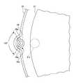
図2は、成膜装置10の概略一部上面図であり、ウエハボート21、反応管22、及び保護管26の位置関係を示している。図示のとおり、反応管22には、ウエハボート21に対して窪んだ溝部22aが形成されている。溝部22aは、本実施形態においては反応管22の下端から上端にまで延びている。溝部22aにより反応管22の内面が外側に窪むため、保護管26を配置するスペースを広げることができる。すなわち、反応管22に溝部22aを形成することは、反応管22とウエハボート21との間の空間が狭い場合に有効である。また、溝部22aを設けることにより反応管22とウエハボート21との間の空間を狭くすると、原料ガスノズル25から供給される原料ガスがウエハWの間の空間に入り込み易くなり、成膜効率が向上する。 FIG. 2 is a schematic partial top view of the
また、保護管16の上端付近(図1参照)には、2つの突起部26aが設けられている。これらの突起部26aは、本実施形態においては、保護管26の中心に対して約120°の角度間隔で配置されている。突起部26aの形状は、図示のような半球状に限らず、柱状(円柱状、角柱状)であっても良く、ピン状であっても良い。なお、突起部26aと反応管22の内面との接触面積を小さくする観点から、突起部26aが柱状の形状を有する場合、先端部が丸くなっていると好ましい。また、突起部26aの大きさは、溝部22aの深さや幅、保護管26の外径、及び反応管22とウエハボート21との間の間隔などに基づいて決定して良い。本実施形態においては、突起部26aの高さ(保護管26の外面からの突起量)は約4mmである。
なお、本実施形態においては、2つの突起部26aの先端部が溝部22aの内面に接しており、しかも2つの突起物26aの角度間隔が約120°であることから、保護管26の反応管22の内面に沿う方向の位置ずれを効果的に抑制できる。Also, two
In the present embodiment, the tips of the two
成膜装置10を用いてウエハWに薄膜を成長する場合には、まず、成膜装置10に併設されるウエハ搬送機構(図示せず)により、反応管22からアンロードされたウエハボート21に対しウエハキャリアからウエハWが搭載される。次に、ウエハボート21が反応管22の内部へロードされ、内部空間(外管23、マニホールド24、及び昇降プレート29により画成される空間)が所定の圧力に排気されるとともに、不図示のパージガス供給ノズルから例えば不活性ガスが供給され、内部空間がパージされる。ヒータ27により、ウエハWを所定の成膜温度(例えば500℃から600℃)に加熱した後、原料ガスノズル25から例えばジシラン(Si2H6)を供給すると、ウエハWの熱によってジシランが熱分解することによりウエハW上にアモルファスシリコン薄膜が成膜される。所定の膜厚を有するアモルファスシリコン薄膜が成膜された後、ジシランの供給を停止し、ウエハWの加熱を停止し、内部空間を不活性ガスでパージした後に、ウエハボート21が反応管22からアンロードされる。この後、搬送機構により、ウエハボート21から例えばウエハキャリアへウエハWを取り出すことにより、成膜プロセスが終了する。When a thin film is grown on the wafer W using the
上述の成膜プロセスにおいては、成膜中に保護管26の外面が反応管22の内面に接触すると、保護管26の外面や反応管22の内面にも薄膜が成膜するため、薄膜により保護管26が反応管22の内面に張り付いてしまう場合がある。この場合、ウエハWの温度を下げる際に、保護管26に比較的大きな応力が働くことが、本発明者らの検討により判明した。ここで、本発明者らが調べた応力の原因について図3を参照しながら説明する。 In the above-described film forming process, if the outer surface of the
図3(a)は、成膜装置10の据え付け後やメンテナンス後など、外管23、反応管22、及びウエハボート21が室温のときのマニホールド24、保護管導入部24d、及び保護管26を示す図である。図示のとおり、保護管導入部24dはマニホールド24からほぼ水平に延びており、したがって保護管26はマニホールド24に対して水平に挿入される。そして、保護管26は、内部空間において上方へ折れ曲がっている。 FIG. 3A shows the manifold 24, the protective
一方、図3(b)は、例えば成膜中など、外管23、反応管22、及びウエハボート21が加熱されたときのマニホールド24、保護管導入部24d、及び保護管26を示す図である。図示のとおり、マニホールド24が熱で変形することにより、保護管導入部24dは下向きに角度θで傾く。実測の結果、本実施形態による成膜装置10においては、ウエハWの温度を400℃まで加熱したとき、マニホールド24の温度は約195℃となり、保護管導入部24dの傾き角度θが約0.35°となっていることが分かっている。保護管導入部24dが傾くと、保護管26もまた傾き、その結果、保護管26は、ウエハボート21と反応管22との間の空間において、反応管22の内面に向かって傾くこととなる。 On the other hand, FIG. 3B is a diagram showing the manifold 24, the protective
ここで、保護管26に突起部26aが設けられていないと仮定すると、反応管22側へ傾いた保護管26は、溝部22aの内面(以下、便宜上、反応管22の内面と記す)に沿って撓み、広い範囲で保護管26の外面と反応管22の内面とが接触することになる。そうすると、成膜中には、反応管22や保護管26に堆積する膜によって、保護管26の外面は反応管22の内面に対して比較的強固に張り付く場合がある。ここで、成膜終了後にヒータ27によるウエハWの加熱を中止すると、マニホールド24の温度も低下していく。これにともない、保護管導入部24dが水平方向(図3(a))に戻っていく。そうすると、外面が反応管22の内面に張り付いている保護管26に曲げ応力が働くこととなる。 Here, assuming that the
次に、保護管導入部24dの傾き角度θのときに、保護管26にどの程度の曲げ応力が働くかを測定した結果について説明する。この測定においては、マニホールド24を加熱することにより保護管導入部24dを傾ける代わりに、マニホールド24を傾けることにより保護管導入部24dを傾け、保護管26に働く荷重をプッシュプルゲージにより測定した。得られた荷重と、保護管26の撓み量及び形状とから保護管26に働く曲げ応力を求めた。なお、保護管26の直立部(ウエハボート21と反応管22との間の空間における部分)の長さは約1350mmであり、保護管26の水平部(保護管導入部24dにより支持される部分)からの高さが150mm、300mm、450mm、及び1330mmの位置での曲げ応力を求めた。 Next, the results of measuring how much bending stress is applied to the
曲げ応力の測定結果を図4に示す。図4のグラフから分かるように、保護管導入部24dの傾き角度θが大きくなるに従って、保護管26に働く曲げ応力は直線状に大きくなる。また、曲げ応力の大きさは、保護管26の直立部の下方ほど大きいことが分かる。具体的には、保護管26の直立部の下端から150mmの位置において保護管26に働く曲げ応力は、下端から1330mmの位置において保護管26に働く曲げ応力の約6倍も大きい。 The measurement result of bending stress is shown in FIG. As can be seen from the graph in FIG. 4, the bending stress acting on the
以上の結果から、保護管26が、成膜中に例えば中央部付近で反応管22の内面に張り付いてしまった場合には、降温時にマニホールド24が元の形状に戻ることによって保護管26が反応管22から離れる方向へ比較的大きな曲げ応力が働くことになる。そうすると、張り付いた部分よりも下の位置において保護管が破損してしまうおそれがある。 From the above results, when the
しかし、本実施形態においては、保護管26の上端(先端)部に突起部26aが設けられているため、昇温時に、マニホールド24の熱変形によって保護管26が反応管の内面に向かう方向に傾いたとしても、反応管22の内面には突起部26aが接触するに過ぎず、保護管26の外面が反応管22の内面に接することがない。このため、保護管26の外面や反応管22の内面に膜が成膜された場合であっても、保護管26の外面が反応管22の内面に張り付いてしまうのを避けることができる。 However, in the present embodiment, since the
また、成膜によって突起部26aが反応管22の内面に張り付いてしまった場合には、保護管26は、その先端部において突起部26aを介して反応管22の内面に固定されることとなるが、図4に示すように保護管26の先端部に働く応力は比較的小さいため、保護管26の破損を回避することができる。また、反応管22の内面に突起部26aが張り付いたとしても、保護管26の外面が張り付く場合とは異なり、接触面積が低減されるため、降温時には、反応管22の内面から外れ易い。そうすると、保護管26の先端部は自由端となるため、保護管26に曲げ応力は働かなくなる。 In addition, when the
ここで、マニホールド24の保護管保持部24dが傾くことにより、保護管26がどのように撓むかについて行ったシミュレーションについて説明する。図5(a)に、このシミュレーションに用いたモデルを示す。保護管26の直立部の長さは1350mmであり、保護管26の太さは約12mmである。また、保護管26と反応管22との間の間隔は、保護管22の下端部において約8mmとし、保護管26の先端部において約4mmとした。すなわち、保護管26の直立部は、反応管22の内面に向かって僅かに傾いている。また、突起部26aが設けられている場合は、突起部26aの位置は、保護管26の先端から20mmの位置とした。また、突起部26aの高さ(保護管26の外面からの突出量)は約4mmとした。すなわち、突起部26aは反応管22の内面に接触していることとした。(言い換えると、突起部26aにより、保護管26の先端部は、反応管22の内面から約4mm離れている。)
また、このシミュレーションにおいては、マニホールド24の保護管導入部24dの傾き角度θを約1.0°とした。この傾き角度の場合に、反応管22が無いと仮定すると保護管26がどの程度傾斜するかを図5(a)中に点線で模式的に示す。Here, the simulation performed about how the
In this simulation, the inclination angle θ of the protective
図5(b)に、保護管26がどのように撓むかを計算した結果を示す。参照符号Wで示すように、突起部26aによって保護管26の先端部の位置は固定されており、保護管26の先端部と下端部の間では、反応管22の内面に向かって膨らむように撓んでいる。しかし、反応管22の内面に最も近い位置(高さが約1050mmの位置)においても、保護管26と反応管22の内面との間には約2.5mmの間隔がある。すなわち、保護管26の先端部に、約4mmの高さを有する突起部26aを設けることにより、保護管26が反応管22の内面に接するのを回避することができる。 FIG. 5B shows the result of calculating how the
また、比較のため、突起部26aが設けられていない保護管26を、その先端部が反応管22の内面に接するように配置した場合において、マニホールド24の保護管保持部24dが約1.0°傾いたときについても検討を行った。その結果、図5(b)に参照符号WOで示すように、計算上、反応管22の内面の位置を超えて保護管26が撓むことが分かった。そうすると、突起部26aが設けられていない場合には、保護管26は、約750mmの高さから上端までの範囲に亘って反応管22の内面に接触し得ると考えることができる。このように接する場合には、成膜中に、保護管26は広い範囲で反応管22の内面に張り付いてしまう可能性がある。しかも、約750mmの高さから上端までの範囲で保護管26が反応管22の内面に張り付いてしまった場合には、保護管26は、反応管22の内面に比較的強固に張り付く一方、その下方で保護管26に働く曲げ応力は比較的大きいため(図4参照)、保護管26が破損する可能性が高くなる。
以上の検討から、保護管26に突起部26aを設ける効果が理解される。For comparison, when the
From the above examination, the effect of providing the
以上、実施形態を参照しながら本発明を説明したが、本発明は、上述の実施形態に限定されることなく、添付の特許請求の範囲の記載に照らして、種々に変形又は変更することができる。 The present invention has been described above with reference to the embodiments. However, the present invention is not limited to the above-described embodiments, and various modifications or changes can be made in light of the description of the appended claims. it can.
例えば、上記の実施形態においては、反応管22には、保護管26に沿って外側に窪んだ溝部22aが形成されているが、溝部22aは必ずしも必要ではなく、例えば図2に対応する上面図である図6(a)に示すように、溝部の無い反応管22に対して、突起部26aが設けられた保護管26を配置しても良い。 For example, in the above-described embodiment, the
また、突起部26aを1つだけ保護管26に設けても良い。ただし、上述のとおり、溝部22aとの関係で、反応管22の内面に沿った方向における保護管26の位置ずれを抑える観点から、2つの突起部26aを設けると好ましい。また、2つの突起物26aの角度間隔は、約120°に限られることなく、保護管26の外面が反応管22(溝部22a)の内面に接触しないようにすることができる限りにおいて、適宜決定して良い。 Further, only one
また、突起部26aは、保護管26にではなく、図6(b)に示すように反応管22の溝部22aに設けても良いし、溝部22aの無い反応管22の内面に設けても良い。これらの場合、1つの突起部26aを設けても良いし、複数個(好ましくは2つ)の突起部26aを設けても良い。さらに、保護管26と反応管22の内面との双方に設けても良い。 Further, the
また、上記の実施形態においては、保護管26は、その先端部に設けた突起部26aが反応管22の溝部22aの内面に接するように配置されるが、室温時において突起部26aが溝部22aの内面に接しないように保護管26を配置しても良い。このように配置することは、昇温時において、保護管26の外面が溝部22aの内面により確実に接しないようにできる点で有利である。
ただし、突起部26aと溝部22aの内面とが離間していると、場合によっては保護管26が振動し、突起部26aが溝部22aの内面に衝突し、パーティクルが発生するおそれがある。これを防ぐためには、突起部26aを溝部22aの内面に接しておくことが好ましい。
また、保護管導入部24dの上下方向の位置によっては、保護管26が反応管22の内面から離れる場合がある。この場合、マニホールド24の熱変形により保護管26が反応管22の内面に向かって傾いていくと、保護管26内の熱電対26aとウエハボート21との距離が変化する。この距離が変化すると、ウエハボート21に保持されるウエハWの温度が見かけ上変化することとなり、ウエハ温度の再現性が悪化するおそれがある。しかし、保護管26の突起部26aが反応管22(又は溝部22a)に予め接するように保護管26を配置しておけば、保護管26とウエハボート21との間隔の変化を低減することが可能となる。したがって、突起部26aの反応管22(又は溝部22a)への離接は、状況に応じて決定して良い。In the above-described embodiment, the
However, if the
Further, the
また、突起部26aの位置は、保護管22の先端部に限られず中間部でも良い(反応管22の内面の中間部でも良い)。これは、中間部に設けられた突起部26aによっても、保護管26が反応管22の内面に直接に接するのを避けることができるためである。このため、保護管26の外面が反応管22の内面に張り付いてしまうのを防ぐことができる。また、中間部に設けられた突起部26aが、反応管22の内面に張り付いたとしても、突起部26aと反応管22の内面との接触面積が小さいため、突起部26aは反応管22の内面から外れ易い。本発明者らの実験によれば、保護管26における下端から約700mmから約800mmまでの位置に突起部26aを設けた場合であっても、保護管26が突起部26aを介して反応管22の内面に強固に張り付くことはない。 Further, the position of the
また、上記の実施形態においては、外管23の内側に反応管22を設け、反応管22の内側にウエハボート21、原料ガスノズル25、及び保護管26が配置されている。このため、外管23の内面に薄膜が成膜するのを低減することができる。一方、反応管22の内面には薄膜が成膜するが、反応管22は外管23に比べて小型であるため、内面に成膜した薄膜を除去するためのクリーニングを行う際の取り扱いが容易である。また、複数の反応管22を用意し、適宜交換する場合においても、複数の外管23を用意し、適宜交換する場合に比べてコストを低減できる。 In the above embodiment, the
また、反応管22を用いずに、外管23の内面に沿って保護管26が延びるように保護管26を配置しても良い。言い換えると、外管23を反応管として用いても良い。この場合であっても、上記の実施形態の効果・利点が発揮されることは明らかである。 Further, the
また、長さ(高さ)の異なる複数本の保護管26を設け、それぞれに1本の熱電対を挿入しても良い。この場合であっても、各保護管26に対して突起部26aを設けることが好ましい。 Further, a plurality of
また、成膜装置10においてウエハWに成膜される薄膜は、アモルファスシリコン膜に限られず、例えば酸化シリコン膜や窒化シリコン膜などであっても良い。 In addition, the thin film formed on the wafer W in the
なお、反応管22に形成された溝部22aの深さ(窪み量)や幅は、使用する保護管26の外径に合わせて適宜決定して良い。また、窪み形状は、円形状の断面(上面形状)に限らず、方形状の断面を有していても良い。溝部22aの断面形状が方形状の場合には、保護管26には、方形状の溝部22aの各面に対応して3つの突起部26aを設けることが好ましい。 In addition, the depth (the amount of depression) and the width of the
上述した、保護管26の長さや直径、及び突起部26aのサイズ等は、例示にすぎず、薄膜を成膜するウエハWのサイズ、1回の成膜プロセスあたりのウエハ枚数に応じて、各成膜装置において適宜決定して良いことは勿論である。 The above-described length and diameter of the
10・・・成膜装置、W・・・ウエハ、21・・・ウエハボート、21c・・・支柱、22・・・反応管、22a・・・溝部、23・・・外管、24・・・マニホールド、24a・・・ノズル導入部、24d・・・保護管導入部、25・・・原料ガスノズル、25a・・・開口、26・・・保護管、26a・・・突起部、27・・・ヒータ、28・・・ペデスタル、29・・・昇降プレート。 DESCRIPTION OF
Claims (6)
Translated fromJapanese前記基板保持具を収容する反応管と、
前記反応管に収容される前記基板保持具に保持される前記複数の基板に対し、前記複数の基板上に成膜される薄膜の原料ガスを供給する原料ガス供給管と、
前記反応管を支持する支持部と、
前記反応管の外側に配置され、前記複数の基板を加熱する加熱部と、
前記支持部に一端部で固定され、前記基板保持具と前記反応管との間において前記複数の基板の配列方向に沿って延び、内部に温度測定部が挿入される保護管と、
前記保護管の外面と前記反応管の内面との少なくとも一方に設けられ、前記保護管の外面と前記反応管の内面との間に空隙を形成する突起部と
を備え、
前記突起部は、前記反応管の内面に接するように前記保護管の外面に設けられている及び/又は前記保護管の外面に接するように前記反応管の内面に設けられている、
成膜装置。A substrate holder for holding the plurality of substrates such that the plurality of substrates overlap with each other at an interval;
A reaction tube containing the substrate holder;
A source gas supply pipe for supplying a source gas of a thin film formed on the plurality of substrates to the plurality of substrates held by the substrate holder accommodated in the reaction tube;
A support for supporting the reaction tube;
A heating unit that is disposed outside the reaction tube and heats the plurality of substrates;
A protective tube fixed at one end to the support, extending along the arrangement direction of the plurality of substrates between the substrate holder and the reaction tube, and having a temperature measurement unit inserted therein;
A protrusion that is provided on at least one of the outer surface of the protective tube and the inner surface of the reaction tube, and that forms a gap between the outer surface of the protective tube and the inner surface of the reaction tube;
The protrusion is provided on the outer surface of the protective tube so as to be in contact with the inner surface of the reaction tube and / or is provided on the inner surface of the reaction tube so as to be in contact with the outer surface of the protective tube.
Deposition device.
前記突起部が、前記保護管の外面と前記反応管の前記溝部の内面とが接触するのを妨げる、請求項1又は2に記載の成膜装置。The reaction tube has a groove recessed along the protective tube;
The film forming apparatus according to claim 1, wherein the protrusions prevent the outer surface of the protective tube from contacting the inner surface of the groove portion of the reaction tube.
Priority Applications (5)
| Application Number | Priority Date | Filing Date | Title |
|---|---|---|---|
| JP2011146244AJP5753450B2 (en) | 2011-06-30 | 2011-06-30 | Deposition equipment |
| KR1020120063197AKR101515095B1 (en) | 2011-06-30 | 2012-06-13 | Film forming apparatus |
| TW101121810ATWI497593B (en) | 2011-06-30 | 2012-06-18 | Film forming apparatus |
| CN201210214836.2ACN102856148B (en) | 2011-06-30 | 2012-06-26 | Film formation device |
| US13/537,597US8833298B2 (en) | 2011-06-30 | 2012-06-29 | Film forming apparatus |
Applications Claiming Priority (1)
| Application Number | Priority Date | Filing Date | Title |
|---|---|---|---|
| JP2011146244AJP5753450B2 (en) | 2011-06-30 | 2011-06-30 | Deposition equipment |
Publications (2)
| Publication Number | Publication Date |
|---|---|
| JP2013016536A JP2013016536A (en) | 2013-01-24 |
| JP5753450B2true JP5753450B2 (en) | 2015-07-22 |
Family
ID=47402626
Family Applications (1)
| Application Number | Title | Priority Date | Filing Date |
|---|---|---|---|
| JP2011146244AActiveJP5753450B2 (en) | 2011-06-30 | 2011-06-30 | Deposition equipment |
Country Status (5)
| Country | Link |
|---|---|
| US (1) | US8833298B2 (en) |
| JP (1) | JP5753450B2 (en) |
| KR (1) | KR101515095B1 (en) |
| CN (1) | CN102856148B (en) |
| TW (1) | TWI497593B (en) |
Cited By (1)
| Publication number | Priority date | Publication date | Assignee | Title |
|---|---|---|---|---|
| JP3042697B2 (en) | 1989-08-26 | 2000-05-15 | ツリュツラー ゲゼルシャフト ミット ベシュレンクテル ハフツング ウント コンパニー コマンディトゲゼルシャフト | Method and apparatus for detecting obstacles in a fibrous material |
Families Citing this family (5)
| Publication number | Priority date | Publication date | Assignee | Title |
|---|---|---|---|---|
| US10228291B2 (en) | 2015-02-25 | 2019-03-12 | Kokusai Electric Corporation | Substrate processing apparatus, and thermocouple |
| JP6579974B2 (en) | 2015-02-25 | 2019-09-25 | 株式会社Kokusai Electric | Substrate processing apparatus, temperature sensor, and semiconductor device manufacturing method |
| JP6602230B2 (en)* | 2016-02-29 | 2019-11-06 | 東京エレクトロン株式会社 | Quartz tube holding structure and heat treatment apparatus using the same |
| JP6952595B2 (en)* | 2017-12-20 | 2021-10-20 | 東京エレクトロン株式会社 | Vertical heat treatment equipment |
| JP7271485B2 (en)* | 2020-09-23 | 2023-05-11 | 株式会社Kokusai Electric | SUBSTRATE PROCESSING APPARATUS, SEMICONDUCTOR DEVICE MANUFACTURING METHOD AND PROGRAM |
Family Cites Families (18)
| Publication number | Priority date | Publication date | Assignee | Title |
|---|---|---|---|---|
| KR19980071011A (en)* | 1997-01-24 | 1998-10-26 | 조셉 제이. 스위니 | High Temperature and High Flow Rate Chemical Vapor Deposition Apparatus and Related Deposition Methods |
| JP2000077346A (en)* | 1998-08-26 | 2000-03-14 | Tokyo Electron Ltd | Heat treatment apparatus |
| US6500266B1 (en)* | 2000-01-18 | 2002-12-31 | Applied Materials, Inc. | Heater temperature uniformity qualification tool |
| TW578214B (en)* | 2000-05-29 | 2004-03-01 | Tokyo Electron Ltd | Method of forming oxynitride film or the like and system for carrying out the same |
| JP2002270593A (en)* | 2001-03-08 | 2002-09-20 | Hitachi Kokusai Electric Inc | Substrate processing equipment |
| US20020195201A1 (en)* | 2001-06-25 | 2002-12-26 | Emanuel Beer | Apparatus and method for thermally isolating a heat chamber |
| JP4509433B2 (en)* | 2001-07-12 | 2010-07-21 | 株式会社日立国際電気 | Substrate processing apparatus and semiconductor device manufacturing method |
| JP4698251B2 (en)* | 2004-02-24 | 2011-06-08 | アプライド マテリアルズ インコーポレイテッド | Movable or flexible shower head mounting |
| JP4426518B2 (en)* | 2005-10-11 | 2010-03-03 | 東京エレクトロン株式会社 | Processing equipment |
| JP4502987B2 (en)* | 2006-01-16 | 2010-07-14 | 株式会社テラセミコン | Batch reaction chamber heating system |
| US7629256B2 (en)* | 2007-05-14 | 2009-12-08 | Asm International N.V. | In situ silicon and titanium nitride deposition |
| US20090035946A1 (en)* | 2007-07-31 | 2009-02-05 | Asm International N.V. | In situ deposition of different metal-containing films using cyclopentadienyl metal precursors |
| JP5347294B2 (en)* | 2007-09-12 | 2013-11-20 | 東京エレクトロン株式会社 | Film forming apparatus, film forming method, and storage medium |
| JP5096105B2 (en)* | 2007-10-23 | 2012-12-12 | ダイダン株式会社 | Structure of underground pile |
| JP5195303B2 (en)* | 2008-10-31 | 2013-05-08 | 山里産業株式会社 | Fluid temperature measuring device and protective tube used therefor |
| JP5529634B2 (en)* | 2010-06-10 | 2014-06-25 | 株式会社日立国際電気 | Substrate processing apparatus, semiconductor device manufacturing method, and substrate manufacturing method |
| JP5545055B2 (en)* | 2010-06-15 | 2014-07-09 | 東京エレクトロン株式会社 | Support structure and processing apparatus |
| JP2012195562A (en)* | 2011-02-28 | 2012-10-11 | Hitachi Kokusai Electric Inc | Attachment for substrate of different diameter, substrate processing apparatus, and method of manufacturing substrate or semiconductor device |
- 2011
- 2011-06-30JPJP2011146244Apatent/JP5753450B2/enactiveActive
- 2012
- 2012-06-13KRKR1020120063197Apatent/KR101515095B1/enactiveActive
- 2012-06-18TWTW101121810Apatent/TWI497593B/enactive
- 2012-06-26CNCN201210214836.2Apatent/CN102856148B/enactiveActive
- 2012-06-29USUS13/537,597patent/US8833298B2/enactiveActive
Cited By (1)
| Publication number | Priority date | Publication date | Assignee | Title |
|---|---|---|---|---|
| JP3042697B2 (en) | 1989-08-26 | 2000-05-15 | ツリュツラー ゲゼルシャフト ミット ベシュレンクテル ハフツング ウント コンパニー コマンディトゲゼルシャフト | Method and apparatus for detecting obstacles in a fibrous material |
Also Published As
| Publication number | Publication date |
|---|---|
| KR20130007428A (en) | 2013-01-18 |
| JP2013016536A (en) | 2013-01-24 |
| US8833298B2 (en) | 2014-09-16 |
| TWI497593B (en) | 2015-08-21 |
| US20130167772A1 (en) | 2013-07-04 |
| TW201310528A (en) | 2013-03-01 |
| KR101515095B1 (en) | 2015-04-24 |
| CN102856148B (en) | 2015-12-16 |
| CN102856148A (en) | 2013-01-02 |
Similar Documents
| Publication | Publication Date | Title |
|---|---|---|
| JP5753450B2 (en) | Deposition equipment | |
| KR101274864B1 (en) | Placement table structure and heat treatment device | |
| KR100386193B1 (en) | Heat treatment device | |
| US8529701B2 (en) | Substrate processing apparatus | |
| US20060005771A1 (en) | Apparatus and method of shaping profiles of large-area PECVD electrodes | |
| US20070148607A1 (en) | Vertical boat and vertical heat processing apparatus for semiconductor process | |
| JP6602230B2 (en) | Quartz tube holding structure and heat treatment apparatus using the same | |
| KR102823346B1 (en) | Substrate processing apparatus, method of manufacturing semiconductor device, substrate processing method and program | |
| JP2012193985A (en) | Substrate processing device and manufacturing method for substrate | |
| JP2013098340A (en) | Deposition apparatus and deposition method | |
| KR100921026B1 (en) | Vacuum processing apparatus and vacuum processing method | |
| KR102391762B1 (en) | Heat treatment apparatus and heat treatment method | |
| JPWO2020189176A1 (en) | Manufacturing method of gas supply unit, substrate processing equipment and semiconductor equipment | |
| US20120037613A1 (en) | Element wire contact prevention member and method for maintenance of heater device | |
| JP2011129679A (en) | Substrate processing apparatus | |
| JP2010016080A (en) | Substrate holding fixture attaching jig and semiconductor manufacturing equipment | |
| JP3868933B2 (en) | Atmospheric pressure CVD equipment | |
| JP5006821B2 (en) | Substrate processing apparatus and semiconductor device manufacturing method | |
| CN217418861U (en) | Epitaxial graphite base | |
| JP5736291B2 (en) | Film forming apparatus and film forming method | |
| JP2009124161A (en) | Thermal processing equipment | |
| JPH07106263A (en) | Reaction furnace | |
| JP6449074B2 (en) | Substrate processing apparatus and substrate processing method | |
| KR101338746B1 (en) | Cvd apparatus | |
| JP2013191695A (en) | Substrate processing apparatus |
Legal Events
| Date | Code | Title | Description |
|---|---|---|---|
| A621 | Written request for application examination | Free format text:JAPANESE INTERMEDIATE CODE: A621 Effective date:20131209 | |
| A977 | Report on retrieval | Free format text:JAPANESE INTERMEDIATE CODE: A971007 Effective date:20140723 | |
| A131 | Notification of reasons for refusal | Free format text:JAPANESE INTERMEDIATE CODE: A131 Effective date:20140819 | |
| A521 | Request for written amendment filed | Free format text:JAPANESE INTERMEDIATE CODE: A523 Effective date:20140918 | |
| A131 | Notification of reasons for refusal | Free format text:JAPANESE INTERMEDIATE CODE: A131 Effective date:20141111 | |
| A521 | Request for written amendment filed | Free format text:JAPANESE INTERMEDIATE CODE: A523 Effective date:20141225 | |
| TRDD | Decision of grant or rejection written | ||
| A01 | Written decision to grant a patent or to grant a registration (utility model) | Free format text:JAPANESE INTERMEDIATE CODE: A01 Effective date:20150519 | |
| A61 | First payment of annual fees (during grant procedure) | Free format text:JAPANESE INTERMEDIATE CODE: A61 Effective date:20150522 | |
| R150 | Certificate of patent or registration of utility model | Ref document number:5753450 Country of ref document:JP Free format text:JAPANESE INTERMEDIATE CODE: R150 | |
| R250 | Receipt of annual fees | Free format text:JAPANESE INTERMEDIATE CODE: R250 | |
| R250 | Receipt of annual fees | Free format text:JAPANESE INTERMEDIATE CODE: R250 | |
| R250 | Receipt of annual fees | Free format text:JAPANESE INTERMEDIATE CODE: R250 | |
| R250 | Receipt of annual fees | Free format text:JAPANESE INTERMEDIATE CODE: R250 | |
| R250 | Receipt of annual fees | Free format text:JAPANESE INTERMEDIATE CODE: R250 | |
| R250 | Receipt of annual fees | Free format text:JAPANESE INTERMEDIATE CODE: R250 |