JP5752744B2 - Guide assembly for bone marrow fixation - Google Patents
Guide assembly for bone marrow fixationDownload PDFInfo
- Publication number
- JP5752744B2 JP5752744B2JP2013113180AJP2013113180AJP5752744B2JP 5752744 B2JP5752744 B2JP 5752744B2JP 2013113180 AJP2013113180 AJP 2013113180AJP 2013113180 AJP2013113180 AJP 2013113180AJP 5752744 B2JP5752744 B2JP 5752744B2
- Authority
- JP
- Japan
- Prior art keywords
- guide
- guide member
- fixture
- distal
- proximal
- Prior art date
- Legal status (The legal status is an assumption and is not a legal conclusion. Google has not performed a legal analysis and makes no representation as to the accuracy of the status listed.)
- Expired - Fee Related
Links
- 210000001185bone marrowAnatomy0.000titleclaimsdescription7
- 210000001519tissueAnatomy0.000claimsdescription27
- 230000001012protectorEffects0.000claimsdescription26
- 239000000463materialSubstances0.000claimsdescription10
- 238000005259measurementMethods0.000claimsdescription9
- 238000001356surgical procedureMethods0.000claimsdescription4
- 210000000988bone and boneAnatomy0.000description41
- 238000000034methodMethods0.000description22
- 238000003780insertionMethods0.000description14
- 230000037431insertionEffects0.000description14
- 239000012634fragmentSubstances0.000description11
- 210000001188articular cartilageAnatomy0.000description10
- 206010017076FractureDiseases0.000description8
- 208000010392Bone FracturesDiseases0.000description6
- 238000009434installationMethods0.000description6
- 230000000712assemblyEffects0.000description4
- 238000000429assemblyMethods0.000description4
- 230000008439repair processEffects0.000description3
- 208000027790Rib fractureDiseases0.000description2
- 238000005553drillingMethods0.000description2
- 239000007943implantSubstances0.000description2
- 230000005855radiationEffects0.000description2
- 210000004872soft tissueAnatomy0.000description2
- 210000000689upper legAnatomy0.000description2
- 238000012800visualizationMethods0.000description2
- OKTJSMMVPCPJKN-UHFFFAOYSA-NCarbonChemical compound[C]OKTJSMMVPCPJKN-UHFFFAOYSA-N0.000description1
- 206010061218InflammationDiseases0.000description1
- 208000001132OsteoporosisDiseases0.000description1
- 239000004696Poly ether ether ketoneSubstances0.000description1
- 206010037802Radius fractureDiseases0.000description1
- 230000001154acute effectEffects0.000description1
- 230000006978adaptationEffects0.000description1
- 238000013459approachMethods0.000description1
- JUPQTSLXMOCDHR-UHFFFAOYSA-Nbenzene-1,4-diol;bis(4-fluorophenyl)methanoneChemical compoundOC1=CC=C(O)C=C1.C1=CC(F)=CC=C1C(=O)C1=CC=C(F)C=C1JUPQTSLXMOCDHR-UHFFFAOYSA-N0.000description1
- 229910052799carbonInorganic materials0.000description1
- 238000004140cleaningMethods0.000description1
- 230000009977dual effectEffects0.000description1
- 230000000694effectsEffects0.000description1
- 230000002708enhancing effectEffects0.000description1
- 210000002758humerusAnatomy0.000description1
- 238000002513implantationMethods0.000description1
- 230000004054inflammatory processEffects0.000description1
- 239000004615ingredientSubstances0.000description1
- 238000011900installation processMethods0.000description1
- 238000012986modificationMethods0.000description1
- 230000004048modificationEffects0.000description1
- 230000000399orthopedic effectEffects0.000description1
- 239000003973paintSubstances0.000description1
- 229920002530polyetherether ketonePolymers0.000description1
- 230000008569processEffects0.000description1
- 210000002320radiusAnatomy0.000description1
- 238000010079rubber tappingMethods0.000description1
- 230000007480spreadingEffects0.000description1
- 229910001220stainless steelInorganic materials0.000description1
- 239000010935stainless steelSubstances0.000description1
- 210000002303tibiaAnatomy0.000description1
- 230000000007visual effectEffects0.000description1
- 210000000707wristAnatomy0.000description1
Images


Classifications
- A—HUMAN NECESSITIES
- A61—MEDICAL OR VETERINARY SCIENCE; HYGIENE
- A61B—DIAGNOSIS; SURGERY; IDENTIFICATION
- A61B17/00—Surgical instruments, devices or methods
- A61B17/56—Surgical instruments or methods for treatment of bones or joints; Devices specially adapted therefor
- A61B17/58—Surgical instruments or methods for treatment of bones or joints; Devices specially adapted therefor for osteosynthesis, e.g. bone plates, screws or setting implements
- A61B17/68—Internal fixation devices, including fasteners and spinal fixators, even if a part thereof projects from the skin
- A61B17/72—Intramedullary devices, e.g. pins or nails
- A—HUMAN NECESSITIES
- A61—MEDICAL OR VETERINARY SCIENCE; HYGIENE
- A61B—DIAGNOSIS; SURGERY; IDENTIFICATION
- A61B17/00—Surgical instruments, devices or methods
- A61B17/16—Instruments for performing osteoclasis; Drills or chisels for bones; Trepans
- A61B17/17—Guides or aligning means for drills, mills, pins or wires
- A61B17/1725—Guides or aligning means for drills, mills, pins or wires for applying transverse screws or pins through intramedullary nails or pins
- A—HUMAN NECESSITIES
- A61—MEDICAL OR VETERINARY SCIENCE; HYGIENE
- A61B—DIAGNOSIS; SURGERY; IDENTIFICATION
- A61B17/00—Surgical instruments, devices or methods
- A61B17/16—Instruments for performing osteoclasis; Drills or chisels for bones; Trepans
- A61B17/17—Guides or aligning means for drills, mills, pins or wires
- A61B17/1739—Guides or aligning means for drills, mills, pins or wires specially adapted for particular parts of the body
- A61B17/1782—Guides or aligning means for drills, mills, pins or wires specially adapted for particular parts of the body for the hand or wrist
- A—HUMAN NECESSITIES
- A61—MEDICAL OR VETERINARY SCIENCE; HYGIENE
- A61B—DIAGNOSIS; SURGERY; IDENTIFICATION
- A61B17/00—Surgical instruments, devices or methods
- A61B17/16—Instruments for performing osteoclasis; Drills or chisels for bones; Trepans
- A61B17/164—Instruments for performing osteoclasis; Drills or chisels for bones; Trepans intramedullary
- A—HUMAN NECESSITIES
- A61—MEDICAL OR VETERINARY SCIENCE; HYGIENE
- A61B—DIAGNOSIS; SURGERY; IDENTIFICATION
- A61B17/00—Surgical instruments, devices or methods
- A61B17/16—Instruments for performing osteoclasis; Drills or chisels for bones; Trepans
- A61B17/1662—Instruments for performing osteoclasis; Drills or chisels for bones; Trepans for particular parts of the body
- A61B17/1686—Instruments for performing osteoclasis; Drills or chisels for bones; Trepans for particular parts of the body for the hand or wrist
- A—HUMAN NECESSITIES
- A61—MEDICAL OR VETERINARY SCIENCE; HYGIENE
- A61B—DIAGNOSIS; SURGERY; IDENTIFICATION
- A61B17/00—Surgical instruments, devices or methods
- A61B17/16—Instruments for performing osteoclasis; Drills or chisels for bones; Trepans
- A61B17/17—Guides or aligning means for drills, mills, pins or wires
- A61B17/1735—Guides or aligning means for drills, mills, pins or wires for rasps or chisels
- A—HUMAN NECESSITIES
- A61—MEDICAL OR VETERINARY SCIENCE; HYGIENE
- A61B—DIAGNOSIS; SURGERY; IDENTIFICATION
- A61B17/00—Surgical instruments, devices or methods
- A61B17/56—Surgical instruments or methods for treatment of bones or joints; Devices specially adapted therefor
- A61B17/58—Surgical instruments or methods for treatment of bones or joints; Devices specially adapted therefor for osteosynthesis, e.g. bone plates, screws or setting implements
- A61B17/88—Osteosynthesis instruments; Methods or means for implanting or extracting internal or external fixation devices
- A61B17/90—Guides therefor
- A—HUMAN NECESSITIES
- A61—MEDICAL OR VETERINARY SCIENCE; HYGIENE
- A61B—DIAGNOSIS; SURGERY; IDENTIFICATION
- A61B17/00—Surgical instruments, devices or methods
- A61B17/56—Surgical instruments or methods for treatment of bones or joints; Devices specially adapted therefor
- A61B17/58—Surgical instruments or methods for treatment of bones or joints; Devices specially adapted therefor for osteosynthesis, e.g. bone plates, screws or setting implements
- A61B17/88—Osteosynthesis instruments; Methods or means for implanting or extracting internal or external fixation devices
- A61B17/92—Impactors or extractors, e.g. for removing intramedullary devices
- A61B17/921—Impactors or extractors, e.g. for removing intramedullary devices for intramedullary devices
- A—HUMAN NECESSITIES
- A61—MEDICAL OR VETERINARY SCIENCE; HYGIENE
- A61B—DIAGNOSIS; SURGERY; IDENTIFICATION
- A61B17/00—Surgical instruments, devices or methods
- A61B2017/00831—Material properties
- A61B2017/00902—Material properties transparent or translucent
- A61B2017/00915—Material properties transparent or translucent for radioactive radiation
- A—HUMAN NECESSITIES
- A61—MEDICAL OR VETERINARY SCIENCE; HYGIENE
- A61B—DIAGNOSIS; SURGERY; IDENTIFICATION
- A61B90/00—Instruments, implements or accessories specially adapted for surgery or diagnosis and not covered by any of the groups A61B1/00 - A61B50/00, e.g. for luxation treatment or for protecting wound edges
- A61B90/03—Automatic limiting or abutting means, e.g. for safety
- A61B2090/033—Abutting means, stops, e.g. abutting on tissue or skin
- A61B2090/034—Abutting means, stops, e.g. abutting on tissue or skin abutting on parts of the device itself
- A—HUMAN NECESSITIES
- A61—MEDICAL OR VETERINARY SCIENCE; HYGIENE
- A61B—DIAGNOSIS; SURGERY; IDENTIFICATION
- A61B90/00—Instruments, implements or accessories specially adapted for surgery or diagnosis and not covered by any of the groups A61B1/00 - A61B50/00, e.g. for luxation treatment or for protecting wound edges
- A61B90/06—Measuring instruments not otherwise provided for
- A61B2090/062—Measuring instruments not otherwise provided for penetration depth
Landscapes
- Health & Medical Sciences (AREA)
- Surgery (AREA)
- Life Sciences & Earth Sciences (AREA)
- Orthopedic Medicine & Surgery (AREA)
- Biomedical Technology (AREA)
- Public Health (AREA)
- Veterinary Medicine (AREA)
- Engineering & Computer Science (AREA)
- Nuclear Medicine, Radiotherapy & Molecular Imaging (AREA)
- Heart & Thoracic Surgery (AREA)
- Medical Informatics (AREA)
- Molecular Biology (AREA)
- Animal Behavior & Ethology (AREA)
- General Health & Medical Sciences (AREA)
- Dentistry (AREA)
- Oral & Maxillofacial Surgery (AREA)
- Neurology (AREA)
- Surgical Instruments (AREA)
Description
Translated fromJapaneseこの発明は、整形外科固定(orthopedic fixation)装置の使用及びその設置の為の装置に関係していて、そして、詳細には、骨髄内固定(intramedullary fixation)装置及び末端橈骨(distal radius)内におけるその設置及び固定を容易にする為の案内に関係している。 The present invention relates to the use of orthopedic fixation devices and devices for their installation, and in particular within intramedullary fixation devices and distal radii. It relates to guidance for facilitating its installation and fixing.
しばしば骨粗しょう症の発生のお蔭で、長い骨の骨折は年を取った人々に明白な普通なことである。長い骨の骨折は、調和した従来の骨板(bone plate)の使用により減らすことが出来る。例えば、骨板(bone plate)は長い骨の2つの隣接した破片の外側表面に取り付けられ、次に骨板(bone plate)中の開口を通した骨ねじ(bone screw)の挿入により固定される。しかしながら、この様な骨板(bone plate)には、骨板(bone plate)を覆っている軟組織が骨板(bone plate)上の通過又は動きにより炎症を生じさせることがあるという問題が生じる可能性がある。 Often due to the occurrence of osteoporosis, fractures of long bones are normal that is obvious to older people. Long bone fractures can be reduced by the use of harmonized conventional bone plates. For example, a bone plate is attached to the outer surface of two adjacent pieces of long bone and then secured by insertion of a bone screw through an opening in the bone plate. . However, such a bone plate may have the problem that the soft tissue covering the bone plate may cause inflammation due to passage or movement on the bone plate. There is sex.
骨板(bone plate)の代わりは、骨折した長い骨の中に規定されている骨髄管(medullary canal)を通って延出する骨髄内(intramedullary)釘又は棒である。これらの釘又は棒は、典型的には、骨ねじ(bone screw)によって長い骨の骨折した部分に固定されている。これらの釘又は棒は、長い骨のいったん中にドリルで形成された孔を通した挿入により骨髄管(medullary canal)中に置かれる。例えば、骨折した大腿骨(femur)を骨髄内(intramedullary)釘又は棒により減少させるには、骨への接近を提供する為に骨端の丸い関節表面(condyles)間の関節性軟骨(articular cartilage)を通して孔がドリルで形成される。骨髄内(intramedullary)釘又は棒は骨髄管(medullary canal)内に収容されているので、これらは板と関連している軟組織に伴う問題を避ける。しかしながら、長い骨の端中の孔を通ったこれらの棒の挿入は、長い骨の端上の関節性軟骨(articular cartilage)を損傷する。 An alternative to a bone plate is an intramedullary nail or stick that extends through a medullary canal defined in a long fractured bone. These nails or bars are typically secured to the fractured portion of long bones by bone screws. These nails or sticks are placed in the medullary canal by insertion through a hole drilled into a long bone. For example, to reduce a fractured femur with an intramedullary nail or rod, articular cartilage between the epiphysic condyles to provide access to the bone ) Through the hole. Because intramedullary nails or rods are housed in the medullary canal, they avoid problems with soft tissue associated with the plate. However, insertion of these rods through holes in the ends of long bones damages the articular cartilage on the ends of long bones.
参照によりその全体がここに組み込まれる、ウォーバートン(Warburton)に対する米国特許第6,527,775号(「‘775特許」)は、橈骨(radius)の末端骨折を減少させるのに使用された骨髄内(intramedullary)固定装置を記載している。「‘775特許」の図3A中に示されている如く、骨髄内(intramedullary)固定装置25は、末端部分27及び基端部分28を伴っている細長い軸方向に延出している棒26を含む。固定装置はまた、末端固定部材30及び基端固定部材35を含む。末端固定部材は、棒の末端部分を通って末端骨折片18中に延出している。基端固定部材は、棒の基端部分及び骨折線に近い橈骨(radius)の部分を通って延出している。 US Pat. No. 6,527,775 (“the '775 patent”) to Warburton, which is incorporated herein by reference in its entirety, is a bone marrow used to reduce radius fractures of the radius. An internal fixed device is described. As shown in FIG. 3A of the '775 patent, the intramedullary fixation device 25 includes an elongated axially extending
さらに、「‘775特許」は、固定部材35a,35bを基端固定開口25a1,25a2中に案内する為の挿入案内装置150を開示している。挿入案内装置は、基端固定開口25a1,25a2と一直線上に配列されていて、ドリル案内として機能する視認指標(visual indicia)153,155を含む。挿入案内150は、棒26の末端部分27に取り付けられ、体の外側に存在している軸方向延出腕を含む。さらに、挿入案内150は、棒を骨髄管(medullary canal)内に挿入する前に棒26に取り付けられる。Further, the “'775 patent” discloses an insertion guide device 150 for guiding the fixing members 35a and 35b into the base end fixing openings 25a1 and 25a2 . The insertion guide device includes visual indicia 153 and 155 which are aligned with the base end fixed openings 25a1 and 25a2 and function as drill guides. The insertion guide 150 is attached to the
「‘775特許」は骨髄管(medullary canal)内への棒の配置を容易にする為の挿入案内装置を開示しているとはいうものの、橈骨(radius)内への固定部材の配置をより容易にする案内組立体を提供することが好ましい。容易に組み立てることが出来るとともに容易に解体することが出来、そして、種々の患者の橈骨(radius)内への固定部材の埋設の為のより効果的な技術を外科医に提供する、案内組立体を提供することも好ましい。 Although the '775 patent discloses an insertion guide device for facilitating the placement of the rod within the medullary canal, the placement of the fixation member within the radius is more desirable. It is preferred to provide a guide assembly that facilitates. A guide assembly that can be easily assembled and disassembled and provides a surgeon with a more effective technique for embedding a fixation member in the radius of various patients It is also preferred to provide.
この発明の実施形態は上述した必要性に向けられ、そして橈骨(radius)の骨髄管(medullary canal)内への固定部材の設置の為の案内組立体を提供することにより他の利点を達成する。案内組立体は大略的には、医師がより容易に固定部材を取り扱うことを許容するとともに種々の寸法の患者への適用を許容する、交換可能な案内組立体を提供する。この案内組立体はまた、設置工程も向上させる、より軽く放射線透過性材料を備えて良い。 Embodiments of the present invention address the above-described needs and achieve other advantages by providing a guide assembly for placement of a fixation member within the radius medullary canal. . The guide assembly generally provides a replaceable guide assembly that allows a physician to more easily handle the fixation member and allows application to various sized patients. The guide assembly may also include a lighter and radiation transmissive material that also improves the installation process.
一実施形態において案内組立体は、固定部材に取り付けられるよう構成されている案内固定具と、前記案内固定具を受け入れ前記固定部材に固定されるよう構成されている案内部材と、を含む。前記案内組立体はまた、前記案内部材と係合するとともに前記案内部材から係合解除されるよう構成された交換可能な末端案内部材を含む。前記末端案内部材は、前記固定部材中に規定されている複数の固定具開口を通って個々の固定具を案内する為の複数の固定具案内開口を規定している。 In one embodiment, the guide assembly includes a guide fixture configured to be attached to a securing member, and a guide member configured to receive the guide fixture and be secured to the securing member. The guide assembly also includes a replaceable end guide member configured to engage and disengage from the guide member. The end guide member defines a plurality of fixture guide openings for guiding individual fixtures through a plurality of fixture openings defined in the fixture member.
前記案内組立体の種々の概念に従えば、前記案内固定具が、橈骨中に規定されている側開口を通して接近可能な前記固定部材の露出された末端に係合するよう構成されている。前記案内固定具はまた、そこを通ったドリル案内を受け入れるよう構成されている開口を含んでよい。前記案内部材が、前記案内部材を通って前記固定部材の前記露出されている端中への前記案内固定具の通路を許容するよう構成されている開口を規定してよい。さらに、前記末端案内部材が、前記案内部材中に規定されている前記開口と直線状に配列されるとともにそこを通った前記案内固定具の通路を許容するよう構成されている開口を含んでよい。前記案内部材が、前記基端案内部材を前記案内部材に固定する固定具を受け入れる為のねじ山が形成された開口を含んでよい。さらに、前記末端案内部材が、前記末端案内部材に関する前記案内部材の回転を阻止する為に、前記案内部材の少なくとも一部分と係合する為の細長孔を含んでよい。 In accordance with various concepts of the guide assembly, the guide fixture is configured to engage an exposed end of the fixation member accessible through a side opening defined in the rib. The guide fixture may also include an opening configured to receive a drill guide therethrough. The guide member may define an opening configured to allow passage of the guide fixture through the guide member and into the exposed end of the fixture member. Further, the end guide member may include an opening arranged linearly with the opening defined in the guide member and configured to allow passage of the guide fixture therethrough. . The guide member may include an opening formed with a screw thread for receiving a fixture for fixing the proximal guide member to the guide member. Further, the end guide member may include an elongated hole for engaging at least a portion of the guide member to prevent rotation of the guide member relative to the end guide member.
前記案内組立体の更なる概念は、前記案内部材に取り付けてよい取っ手を提供することを含む。前記案内組立体はさらに、前記末端案内部材と係合するとともに前記末端案内部材との係合を解除するよう構成されている交換可能な基端案内部材を更に含んでよく、ここにおいて前記基端案内部材は、前記末端案内部材を介して規定されている前記複数の固定具開口の基端近傍に配置されていて前記骨髄内固定部材中に規定されている複数の固定具開口中に個々の固定具を案内する為の複数の固定具案内開口を規定している。前記末端案内部材は突起を含んでよく、そして前記基端案内部材はその中に前記突起を受け入れる為の通路を含んでよい。前記基端案内部材及び前記末端案内部材が、ねじ山係合の為に構成されていて良い。さらに、前記末端案内部材が、前記基端案内部材中に規定されている開口と係合するよう構成されている直線状配列ピンを含んでよい。前記案内組立体はさらに複数の組織保護体を含んでよく、ここにおいて前記基端案内部材及び前記末端案内部材の前記複数の固定具案内開口の夫々がそこを通って個々の組織保護体を受け入れるよう構成されていてよい。前記基端案内部材及び前記末端案内部材が橈骨から外方に離れていて、前記組織保護体が前記基端案内部材及び前記末端案内部材を通って橈骨の近傍に延出するよう構成されている。さらに、前記案内組立体は複数のドリル案内を含んでよく、ここにおいて前記複数の組織保護体の夫々はその中に前記ドリル案内の個々を受け入れるよう構成されている。 A further concept of the guide assembly includes providing a handle that may be attached to the guide member. The guide assembly may further include a replaceable proximal guide member configured to engage and disengage the distal guide member, wherein the proximal guide member is configured to be disengaged from the distal guide member. A guide member is disposed in the vicinity of the proximal ends of the plurality of fastener openings defined through the distal guide member and is individually disposed in the plurality of fastener openings defined in the intramedullary fixation member. A plurality of fixture guide openings for guiding the fixture are defined. The distal guide member may include a protrusion, and the proximal guide member may include a passage for receiving the protrusion therein. The proximal guide member and the distal guide member may be configured for thread engagement. Further, the distal guide member may include a linear alignment pin configured to engage an opening defined in the proximal guide member. The guide assembly may further include a plurality of tissue protectors, wherein each of the plurality of fixture guide openings in the proximal guide member and the distal guide member receives an individual tissue protector therethrough. It may be constituted as follows. The proximal guide member and the distal guide member are spaced outward from the rib, and the tissue protector extends through the proximal guide member and the distal guide member to the vicinity of the rib. . Further, the guide assembly may include a plurality of drill guides, wherein each of the plurality of tissue protectors is configured to receive an individual of the drill guides therein.
この発明の更なる実施形態は、橈骨骨折を修復する為の骨髄内固定部材キットを提供する。このキットは、橈骨の骨髄内管内に位置されるよう構成され、そこを通って個々の固定具を受け入れる為の複数の固定具開口を規定している骨髄内固定装置を含む。このキットはまた、前記骨髄内固定装置連結するよう構成されている案内部材と、前記案内部材と係合するとともに前記案内部材から係合を解除するよう構成されている交換可能な末端案内部材と、を含む。前記末端案内部材は、前記骨髄内固定部材中に規定されている複数の固定具開口を通って個々の固定具を案内する為の複数の固定具案内開口を規定している。このキットはまた、交換可能な基端案内部材及び/又は案内固定具を、上述した如く、含んでよい。 A further embodiment of the present invention provides an intramedullary fixation member kit for repairing rib fractures. The kit includes an intramedullary fixation device configured to be positioned within the intramedullary canal of the rib and defining a plurality of fastener openings therethrough for receiving individual fasteners. The kit also includes a guide member configured to couple the intramedullary fixation device, and a replaceable end guide member configured to engage and disengage from the guide member. ,including. The distal guide member defines a plurality of fixture guide openings for guiding individual fixtures through a plurality of fixture openings defined in the intramedullary fixation member. The kit may also include a replaceable proximal guide member and / or guide fixture as described above.
この発明のさらなる実施形態は、橈骨の骨髄管内に固定部材を置く為の方法に関係している。この方法は、その骨髄管内に延出した側開口を橈骨中に規定すること、及び、案内固定具により案内部材を前記固定部材に取り付けること、を含む。この方法はさらに、前記固定部材が前記骨髄管及び側開口中に位置されるまで前記側開口を通って前記固定部材を挿入すること、及び、複数の固定具案内開口を規定している交換可能な末端案内部材を前記案内部材に取り付けることを含む。さらに、この方法は、前記固定部材中に規定されている複数の固定具開口と一直線状に配列されていて前記末端案内部材中に規定されている前記複数の固定具案内開口を介し前記橈骨内に複数の固定具開口を規定することを含む。この方法はまた、前記末端案内部材中に規定されている前記複数の固定具案内開口と、前記固定部材及び前記橈骨中に規定されている前記複数の固定具開口と、を通って複数の骨固定具を進ませることを含む。 A further embodiment of the invention relates to a method for placing a fixation member within the medullary canal of the radius. The method includes defining a side opening in the rib that extends into the medullary canal and attaching a guide member to the fixation member with a guide fixture. The method further includes inserting the fixation member through the side opening until the fixation member is positioned in the medullary canal and the side opening, and a replaceable defining a plurality of fixture guide openings Attaching an end guide member to the guide member. Further, the method includes the step of aligning the plurality of fixture openings defined in the fixing member with the plurality of fixture guide openings defined in the distal guide member. Defining a plurality of fastener openings. The method also includes passing through the plurality of fastener guide openings defined in the end guide member and the plurality of fastener openings defined in the fixation member and the ribs. Including advancing the fixture.
この方法の変形例は、複数の固定具案内開口を規定している交換可能な基端案内部材を前記末端案内部材に取り付けることを含む。 A variation of this method includes attaching a replaceable proximal guide member defining a plurality of fixture guide openings to the distal guide member.
この方法はさらに、前記末端案内部材を介して規定されている前記複数の固定具開口の近傍に配置されていて前記固定部材中に規定されている複数の固定具開口と直線状に配列されている前記基端案内部材中に規定されている複数の固定具案内開口を介して前記橈骨内に複数の固定具開口を規定すること含んでよい。さらに、この方法は、前記案内部材が前記固定部材に取り付けられている間に前記案内部材から前記末端案内部材を取り外すことを含んでよい。 The method is further arranged in the vicinity of the plurality of fixture openings defined via the end guide members and arranged in a straight line with the plurality of fixture openings defined in the fixation member. There may be included defining a plurality of fastener openings in the ribs via a plurality of fastener guide openings defined in the proximal guide member. Further, the method may include removing the end guide member from the guide member while the guide member is attached to the fixed member.
この発明が一般的な言葉で記載されたが、今度は参照が添付の、尺度を引く必要がない図面に対して為され:
この発明は、これ以降に添付の図面を参照しながらより十分に記載されるが、ここにおいてはこの発明の全てではなく幾つかが示されている。実際には、この発明は、多くの異なった形態で具体化されて良く、ここに明らかにされた実施形態に限定されると解釈されてはならず、むしろ、これらの実施形態はこの記載が適用可能な法律上の要求を十分に満たすよう提供されている。これを通じて同じ番号は同じ部材を引用している。 The invention will now be described more fully with reference to the accompanying drawings, in which some, but not all, of the invention are shown. Indeed, the invention may be embodied in many different forms and should not be construed as limited to the embodiments set forth herein; rather, these embodiments are described by this description; Provided to fully meet applicable legal requirements. Throughout this, the same numbers refer to the same parts.
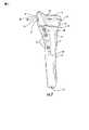
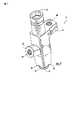
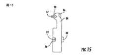
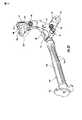
この発明の一実施形態の案内組立体10は、図1中において患者の橈骨(radius)11に連結されて示されている。案内組立体10は、以下にさらに詳細に説明されている如く、橈骨(radius)11内に固定部材20を設置する為に採用されている。固定部材20は、骨折が関節性軟骨(articular cartilage)表面12近傍の一端であり、そして、修復の間に関節表面(articular surface)を崩壊しないようにしておくことが望まれる場合に、末端橈骨(distal radius)の骨折を修復する為に最も適している。ここにおいて参照が橈骨(radius)11の為に適している案内組立体10及び固定部材20に対し為されているが、案内組立体は、大腿骨(femur),脛骨(tibia),橈骨(radius),又は上腕骨(humerus)の如き種々の長い骨の内に固定部材を設置するよう構成されていて良いことが理解される。 A
図2中に示されている如く、橈骨(radius)は大略的に、より細い幹(shaft)14に向かい先細になっていて関節性軟骨(articular cartilage)表面を支持している幅広端13を含む。幹(shaft)14内を延出していて幅広端13の一部であるのは骨髄管(medullary canal)15である。さらに、案内組立体10及び固定部材20は、長い骨の種々の骨折を修復するのに使用されることが出来るが、単一の骨折線18により第2骨片17から離れた第1骨片16を修復するのに使用されているのが示されている。側開口19が、固定部材20の挿入を許容する為に、関節性軟骨(articular cartilage)表面12の下にある、幅広端13の側表面中に規定されている。 As shown in FIG. 2, the radius generally has a
大略的に、固定部材20は、そこを通して複数の固定具21を受け入れ、そして、図2中に示されている如く、例えば骨折線18の上下で橈骨(radius)11に取り付け、それにより骨折を減少させるよう構成されている。細長い固定部材20は、橈骨(radius)11の骨髄管(medullary canal)15内に位置した時、側開口19の近傍に位置された第1端22を有する。第1端から開口の残りを通って第1骨片16の骨髄管(medullary canal)15内に延出しているのは、固定部材20の湾曲した本体24(図2中では点線で示されている)である。湾曲した本体24は第2骨片17の骨髄管(medullary canal)15内に位置された第2端23まで延出している。好ましくは、湾曲した本体24の湾曲の半径は、開口19を通った骨髄管(medullary canal)15内への湾曲した本体の滑らかな挿入を促進するよう選択されている。 In general, the
例えば、この発明の固定部材20の一実施形態が図3乃至図6中に示されている。固定部材20の第1端22は、図4中に示されている如く、側開口19を通って接近可能である露出された第1端表面27及び露出された表面に対し直角である隣接した第1端表面28を含む、2つの交差している平面を有している。固定部材20の第2端23は丸まった輪郭を有して良い。 For example, one embodiment of the fixing
固定部材20の湾曲した本体24は、湾曲した本体の反対側面である、凸状側面29及び凹状側面30を含む。これらの側面は同じ中心を伴う湾曲の半径を有しているが、凸状側面の中心は、図4中に示されている如く、これらの側面が第2端23に向かい延出する時に僅かに先細に集束するよう変化している。例えば、凹状側面30の湾曲の半径は約3.12インチであり、そして、凸状側面29の湾曲の半径は、隣接した第1端表面28の平面から約2.31インチであり露出された第1端表面27の平面から約2.35インチに位置決めされている第1中心31から測定された時の第1端22近傍では約3.40インチである。注目すべきは、この幹(shaft)が、固定部材20の第2端23に近い先細り(taper)を提供していることである。 The
図3,5,そして6中に示されている如く、反対の側面33の第2の対が凸状側面29及び凹状側面30の間を延出している。凸状側面29及び凹状側面30と同様に、側面33は、それらが湾曲した本体24の第1端22から第2端23まで延出した時に相互に向かい僅かに先き細になっている。しかしながら、図示されている実施形態において側表面33は、側表面29,30の湾曲した形状とは反対に、比較的平坦である。好ましくは、側面29,30,33の先き細り(taper),端22,23間の湾曲した本体24の連続している湾曲,そして第2端23の丸まった輪郭は、側開口19を通った骨髄管(medullary canal)15内への挿入を容易にする手助けをする。 As shown in FIGS. 3, 5 and 6, a second pair of opposite side surfaces 33 extends between the
固定部材を通った固定具21の通路を許容する為に、複数の固定具開口が固定部材中に規定されている。これらの固定具開口は、側開口接近可能固定具開口34,湾曲している凸状側面29及び凹状側面30の間を延出している1対の固定具開口35,そして、側面33の間を延出している固定具開口36を含む。図4中に示されている如く、固定具開口34は、(固定部材20が設置された時に側開口19を通って石器可能である)露出されている第1端表面27から湾曲した本体24の一部を通り凸状側面29まで延出している。固定具開口34は、案内部分38及び、案内部分よりも全体的により細い固定具部分39を含んでいる。これらの部分の両方は、以下により詳細に記載される如く、固定具21及び種々の設置装置による固定適合を容易とするようねじ山が形成されて良い。固定具開口34の案内部分38の周辺の周りに規定されているのは、4つの凹所40である。これらの凹所40は十字形状に配置されていて、夫々は互いに90°離れて固定具開口34から外に放射状になっている。以下により詳細に記載される如く、凹んでいる凹所40は案内組立体10との確実な、適切に方向付けされた、完全な適合を提供するよう働く。 In order to allow passage of the
側面29,30間を延出する1対の固定具開口35は、図2,5,そして6中に示されている如く、第1端22により近く湾曲した本体24を通って第1骨片16中にあるように延出している。固定具開口35の夫々は、固定具開口34と同様にねじ山が形成された固定具部分を有してよく、しかし対となる孔(counter bore)を規定するねじ山が形成されていない固定具頭部分を有してもよい。これらの固定具開口35は、図3,5,そして6中に示されている如く、凸状側面29及び露出されている第1端表面27に関し相対的に直角になっている固定具開口34の向き及び互いよりも、異なった散開する角度で延出する。結果として、(固定具開口35の如き)固定具開口は、固定部材の軸に対していつも直線状に配列されている必要はない。 A pair of
これら異なった角度は、図2中に示されている如く、第1骨片16の異なった部分中への固定具21の傾斜した挿入を許容することにより固定を向上させる。さらに、固定具開口34,35の角度は、向上された固定の為に固定具が関節性軟骨(articular cartilage)の下へ延出するよう、構成されていて良い。一般的には、これは固定具開口34,35が、固定部材20に対し、(固定具開口の起源(origin)に従って)約50°と約85°との間、そして好ましくは約60°乃至約70°、の角度の如き幾らか鋭角で延出することを要求する。基本的には、これらの角度は、関節性軟骨(articular cartilage)の為の控え壁(buttress)を提供するよう関節表面の傾斜角度に合致する。例えば、橈骨(radius)上の関節性軟骨(articular cartilage)の尺骨側の傾斜角度(ulnar inclination angle)は約23°(67°の固定具開口角度になる)である。控え壁(buttress)効果はまた、関節性軟骨(articular cartilage)の下に横たわるよう、露出している第1端表面27の近傍における、露出している第1端表面27に関し直角での、第1端表面28の肋軟骨下の(sub-chondral)載置によっても向上される。 These different angles improve the fixation by allowing for the inclined insertion of the
図3及び4中に示されている図示された実施形態においては、6個の固定具開口36が、固定部材20の第2端23により近い位置で湾曲された本体24中に規定されている。より大きな直径を有している固定具開口36は、固定具開口34,35と同様に、そこを通ったねじ山が形成されている固定具21を受け入れるよう構成されていて、より小さな直径を有している固定具開口は比較的小さな直径のキルシュナー(Kirschner)ワイヤー/K―ワイヤー41を受け入れるよう構成されている。より大きな固定具開口36は、ねじ山を損傷することのない、固定部材20を通ったねじ山が形成されている固定具の滑り適合を許容するよう、ねじ山が形成されていなくとも良い。さらに、図2は、より大きな固定具開口36の夫々が第2骨片17中で個々の固定具21を案内しても良いように、固定部材29が橈骨(radius)11内に位置されてよいことを見せている。 In the illustrated embodiment shown in FIGS. 3 and 4, six
6個の固定具開口が図示されている固定部材20中に示されているが、固定部材は所望の如何なる数の固定具開口を含んで良いことが理解される。例えば、固定部材20は、寸法3又は4の埋設物への増大が追加の固定具開口35及び/又は36を含んでよい寸法1又は2の埋設物になるよう構成されていて良い。さらに、固定部材20は、長い骨の型,患者,及び/又は他の要素に従って種々の構成であることが出来る。この発明の追加の実施形態に従っている固定部材及び骨固定具に関するさらなる詳細の為に、出願人は、2004年7月15日に提出された米国特許出願公開番号2006/00151011を引用することによりその全体をここに組み込む。 Although six fastener openings are shown in the illustrated
図1は、この発明の一実施形態に従っている案内組立体10を図示している。案内組立体は大略的に、案内部材51,末端案内部材52,そして基端案内部材53を含む。以下に詳細に議論するように、案内部材51,そして末端52及び基端53案内部材は、橈骨(radius)11内での固定部材20のより容易な設置の為に提供してよい交換可能な案内組立体10を提供するよう、互いに係合されることが出来るし互いに係合解除されることができる。 FIG. 1 illustrates a
図7乃至9は、この発明の一実施形態に従っている案内部材51を図示している。案内部材51は、案内固定具54を介して固定部材20の末端に連結されるよう構成されている。詳細には、案内部材51は、そこを通って案内固定具54を受け入れるよう構成されている長手方向開口36を含む。案内固定具54は、固定部材20の固定具開口34中に規定されているねじ山と合致するよう構成されているねじ山が形成されている端58を含む。さらに、案内部材51は、例えば図33中に示されている如く、同様に形作られているが幾分小さい凹状の凹み40中に、直接的、又は干渉、形式の適合で適合するよう構成されている複数の枝(prong)60を含む。 7-9 illustrate a
ねじ山が形成されている端58が案内部分38のねじ山中に進められた時、案内部材51及び、凹み40と同様な十字形状配置で離れている、その枝(prong)60は凹み中に進められる。直接的な適合と組み合わされた十字形状配置は、末端52及び基端53案内部材を取り付ける以前に、種々の固定具21の挿入の案内中も同様に、案内部材51を固定部材20に強固に固定する。十字形状及び直接的な適合は、案内組立体及び固定部材の相対的に長く片持ち梁状の構成の故に問題になることが出来る、案内組立体10と固定部材20との間の回転を制限することに有効となる。しかしながら、凹み40中の枝(prong)60の直接的な適合(positive fit)は、固定部材20の露出されている第1端面27の代わりに案内部材51上に凹みを設けることによるの如き、他の方法によっても達成されることが出来ることに注目すべきである。 When the threaded
案内部材51はまた、図32−34,36,そして37中に示されている如く、取っ手台62及び、そこを通り延出していて取っ手114と合致するよう構成されているねじ山が形成された開口64を含む。取っ手114は、以下に追加的に詳細に説明される如く、骨髄管(medullary canal)15内で固定部材20を操作する為に典型的に使用されている。さらに、案内部材51は、またねじ山が形成されている開口68を含む突起66を含む。また以下にさらに詳細に説明される如く、突起は末端案内部材52中に規定されている細長孔(slot)76と合致するよう構成されている。突起66は大略的に長方形状として示されているが、干渉型(interference type)の適合中において先細り長孔(tapered slot)と係合するよう先細にされている(tapered)如き、末端案内部材52の細長孔(slot)76と合致するように種々の寸法にされ構成されていることが出来る。 The
図10乃至13は、この発明の詳細な実施形態に従っている末端案内部材52を図示している。図10乃至13中に示されている末端案内部材52は、固定部材20の第1端22及び第1骨片16内に固定具21を案内する為に使用されてよい。詳細には、図10及び13中に示されている末端案内部材52は、患者の左橈骨(radius)11内に固定具21を案内するよう構成されていて良く、図11及び12中に示されている末端案内部材52は、右橈骨(radius)11内に固定具を案内するのに使用されて良い。 10-13 illustrate a
図10乃至13中に示されている末端案内部材52の夫々は、複数の開口70を含む。開口70は、固定部材20の湾曲した本体24中に規定されている対になっている開口35の軸と同軸(collinear)で一直線状に配列されるよう方向付けされている。一実施形態に従えば、開口70は、図2中に示されている如く、固定具21が関節性軟骨(articular cartilage)表面12の下方で第1骨片16中に或る角度で延出するよう規定されている。 Each of the
さらに、開口70は、図34中に示されている如く、そこを通って組織保護体72を摺動可能に受け入れるよう構成されている。個々の組織保護体72は、頭75及び長手方向軸77を含んでおり、ここにおいて軸は開口70を通って橈骨(radius)の近傍まで延出するよう構成されている。従って、組織保護体の末端は皮膚を通って挿入され橈骨(radius)に当接することが出来る。末端案内部材52と患者の皮膚との間の離れた距離(offset distance)は、末端案内部材52が種々の寸法の患者を受け入れることを許容し、組織保護体72が、例えば組織中へのドリルによる穴あけからの如き固定部材20を埋設することから生じる障害から患者の皮膚を保護する。さらに、末端案内部材52は、図20及び21中に示されている如く、そこを通って案内固定具54を受け入れるよう構成されている開口74を含む。図1及び34は、組織保護体72及び案内固定具54が、橈骨(radius)11内の固定部材20の設置を容易とするよう、ドリル刃(drill bits),K−ワイヤー,ドリル案内,固定具,そしてそれらと同様なものを受け入れるよう構成されている個々の長手方向開口73を含む。例えば、図1は、組織保護体72の夫々を示していて、そして案内固定具54はその中に位置したドリル案内78を有して良い。 In addition, the
個々の末端案内部材52はまた、案内部材51の突起66と合致するよう構成されている細長孔(slot)76を含む。細長孔(slot)76中を延出しているのは、突起66のねじ山68と係合するよう構成されているねじ山付き端82を有している固定具80である。細長孔(slot)76内の突起66及び固定具80の係合は、橈骨(radius)11内における固定具21のより正確な設置を確実にすることが出来る、案内部材51及び末端案内部材52の間の回転運動に対する抵抗を提供する。細長孔(slot)76は大略的に長方形状であるが、突起66と合致しそれらの間の回転運動に抵抗するよう種々の寸法及び形状に変形されることが出来る。 Each
図10乃至13中に示されている個々の末端案内部材52は、患者の手首周辺の周りに部分的に延出するとともに末端案内部材53に係合するよう構成されている湾曲を有したフック形状部分84を含む。図10乃至13の末端案内部材52は、図23中に示されている如く、固定部86、及び基端案内部材53中に規定されている開口92にねじ込まれるよう構成されている対応するねじ山が形成されている端87を含む。しかしながら、基端案内部材53は、基端案内部材及び末端案内部材が互いにねじ山で係合可能になるよう末端案内部材52中に規定されているねじ山に係合するよう構成されている固定具を含むことが出来ることが理解される。さらに、図10乃至13の末端案内部材52は、基端案内部材53中に規定された開口94と係合するよう構成された直線状整列ピン88を含んでおり、基端案内部材53はまた末端案内部材52中に規定された開口90と係合するよう構成された直線状整列ピン96を含んでいて良い。従って、直線状整列ピン、及び末端52及び基端53案内部材間のねじ山係合の組み合わせは、確実な取り付けを提供し、また、異なった寸法の末端案内部材に交換するよう、末端案内部材を取り外すという選択肢を外科医に提供する。 The individual
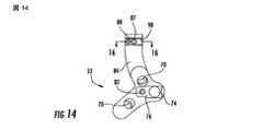
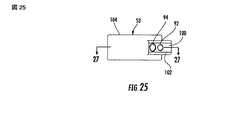
図14乃至19は末端案内部材52の追加の実施形態を図示しており、図14乃至16の末端案内部材52は右側橈骨(radius)の為に採用してよく、図17乃至19の末端案内部材52は左側橈骨(radius)の為に使用してよい。図14乃至19の末端案内部材52は図10乃至13の基端案内部材と同様であるが、末端案内部材52を基端案内部材53に連結する為の異なった技術を提供する。より詳細には、フック形状部分84は、図14及び17中に示されている如く、その幅を横切って延出する突起98を含む。突起98は、図25乃至27中に示されている基端案内部材53中に規定されている通路100と係合するよう構成されている。従って、通路100中での突起98の係合は、末端52及び基端53案内部材間の回転運動に対する追加の抵抗を提供してよい。前述した如く、図14乃至19の末端案内部材52は、基端案内部材53中に規定されているねじ山が形成されている開口92と係合するよう構成されている固定具86を含んでいるとともに、基端案内部材53中に規定されている開口54に係合するよう構成されている直線状配列ピン88も含んでいる。 14-19 illustrate additional embodiments of the
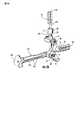
案内組立体10はさらに、この発明の追加の実施形態に従っていて図24乃至図28中に示されている如く、固定部材20の第2端23及び第2骨片17内での固定具21の案内の為の基端案内部材53を含む。基端案内部材53は、図29中に示されている如く、個々の末端案内部材52と係合するよう構成されている。詳細には、図24の基端案内部材53は大略的には、図10乃至13中に示されている末端案内部材52に連結されるよう構成されている。 The
基端案内部材53は大略的にはL字形状をしており、そして、末端案内部材52と係合する為の第1部分102と、個々の固定具21を固定部材20中に規定されている個々の開口36中に案内する為の第2部分104と、を含む。詳細には、第2部分104は、図34中に示されている如く、管状保護体72の如き、固定部材20を埋設する為の種々の装置を受け入れるよう構成されている複数の開口106を含む。さらに、第2部分104は、その中にK−ワイヤー41又は同様な装置を受け入れるよう構成されていることが出来るより小さな開口108を含む。 The
図25乃至27はこの発明の追加の実施形態に従っている基端案内部材53を図示していて、それは図14乃至19中に図示されている末端案内部材52と連結されるよう構成されている。前述した如く、基端案内部材53は、図32及び33中に示されている如く、突起98を受け入れるよう構成されている通路100を含む。異なった基端案内53はまた、異なった寸法の固定部材20の為に使用されることが出来る。例えば、図28は、より長い固定部材20を収容する為の追加の開口106を有している基端案内部材53を示している。さらに、基端案内部材53は、治療される長い骨の型及び側開口19の向き次第で右手側及び左手側形状を採用することが出来る。 FIGS. 25-27 illustrate a
図29は、案内組立体10種々の固定具と係合するよう構成されているレンチ(wrench)110を図示している。例えば、図29は、レンチ(wrench)110が、ねじ山が形成されている端87を基端案内部材53のねじ山が形成されている開口92内で締め付けるよう固定具86の頭と合致するよう構成されている。レンチ(wrench)110はまた、案内固定具54及び固定具80の頭と一致可能である。従って、レンチ(wrench)110は、案内組立体10を組み立てるとともに案内組立体を固定部材20に固定するのに使用される異なった固定具と使用されてよい万能工具を提供する。レンチ(wrench)110は、重量を減少させる為に、複数の長手方向細長孔(slot)112を含んでよい。 FIG. 29 illustrates a
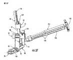
手短に前述した如く、案内部材51は、取っ手114を受け入れるよう構成されているねじ山が形成された開口64を含む。取っ手114は典型的には、側開口19を通った骨髄管(medullary canal)15中への固定部材20の設置を容易にするよう案内部材51に取り付けられる。取っ手114は典型的には、本体部分116及びその中に規定された複数の細長孔(slot)118を含む。さらには、取っ手114は、図38中に示されている如く、本体部分116の長さを延出した軸121及び案内部材51のねじ山が形成されている開口64と合致するよう構成されているねじ山が形成されている端123を含む打ち板(strike plate)120を含んでよい。従って、反時計回り方向又は時計回り方向における打ち板(strike plate)120の回転が、案内部材51に対する軸121の緩み又は締め付けを生じさせてよい。さらに、外科医は、橈骨(radius)11内への固定部材20の埋設を手助けする為にハンマー(hammer)により打ち板(strike plate)120と接触してよい。本体部分116は、固定部材20が橈骨(radius)11内に配置されることによりその中に骨片を受け入れ、細長孔(slot)118は、骨片の取り除きの為の又はその他に固定部材を設置させている間に橈骨(radius)から取り除かれた如何なる骨片の清掃の為の技術を提供する。如何なる数の細長孔(slot)118が本体部分14中に規定されていてよく、そして、細長孔(slot)は、図33中に示されている如く、本体部分の全長さを延出してよく、或いは複数の軸方向に直線状に整列した細長孔を含んでよい。 As briefly described above, the
案内組立体10はまた、図1中に示されている如く、複数のドリル案内78を含む。ドリル案内78は、ドリル刃(drill bit)を受け入れるとともに、橈骨(radius)11内にドリルで形成された孔の深さの測定を容易にする為に採用されている。図35中に示されている如く、ドリル案内78は、橈骨(radius)11内における孔の深さを基にして適切な長さの固定具21及び/又はK−ワイヤー41を決定する為に外科医により使用される複数の測定指標122を含んでよい。ドリル案内78は、組織保護体72の開口73内で孔34,35,及び/又は36を通って橈骨(radius)11内へ摺動するよう構成されている軸124を含む。さらに、ドリル案内78は、ドリル案内の長さを延出しその中にドリル刃又はK−ワイヤー41を摺動可能に受け入れるよう構成された長手方向細長孔(slot)126を含む。ドリル案内78の細長軸124内に規定されているのは、幅広い直径からその末端近傍のより細い直径まで先細(taper)になっている案内軸開口である。従って、2重直径ドリル刃(drill bit)が橈骨(radius)11内に孔をドリルで形成するのに使用されることが出来、ここにおいては、ドリル刃のより大きな直径は、ドリル案内78の末端近傍に規定された肩を超えたドリル刃(drill bit)の移動を阻止し、選択された深さを超えたドリルによる孔明けを阻止する。図1中に示されている如く、橈骨(radius)11内にドリルで形成された孔の深さは、測定指標122の一つとのK−ワイヤー41上の予め定められている印の直線状配列に基づいて決定されてよい。K−ワイヤー41及び/又は測定指標122はまた、測定の読み取りを容易とするよう蛍光塗料又は溝がつけられた刻み目を採用できる。さらに、ドリル案内78は、外科医が橈骨(radius)11内におけるK−ワイヤーを見ることを手助けするよう、K−ワイヤー41がそこに挿入されている間に個々の組織保護体72から除去されていることが出来る。組織保護体72はまた、もし望むのであれば、橈骨(radius)11を見ることが出来るように、K−ワイヤー41が橈骨(radius)11内に挿入されている間に末端52及び基端53案内部材から除去されることが出来る。 The
末端52及び基端53案内部材は、放射線透過性材料(radiolucent material)であってよい。従って、末端52及び基端53案内部材は、固定部材20の埋設の間に、レントゲン写真技術を使用して取られた画像の如く、橈骨(radius)11の取られた画像を遮断しない。例えば、放射線透過性材料(radiolucent material)は、従来のステンレス鋼案内組立体よりも軽い、炭素強化PEEK材料(carbon reinforced PEEK material)であることが出来る。より軽い材料を備えている案内組立体10は、外科医により容易に取り扱われ、骨片上により小さなねじれ力(torque)を負荷する。さらに、組織保護体72,K−ワイヤー41,及び/又は取っ手本体116の如き案内組立体の他の材料は、案内組立体10の重量を減少させるとともに、手術中における橈骨(radius)内の固定部材20のより良い視認を提供するよう、放射線透過性材料(radiolucent material)であることが出来る。 The
固定部材20を設置する為に、側開口19が橈骨(radius)11の側方において開かれ、そして、海綿状骨(cancellous bone)の骨髄管(medullary canal)15を開くのに従来の骨きり(bone awl)(図示されていない)が使用されて良い。固定部材20の寸法に接近するために、側開口19を通って骨髄管(medullary canal)15中へと試行ブローチ(trialing broach)が付勢されて(urged)良い。リーマー(reamer)及びきり(awl)の如き他の従来の工具もまた骨をきれいにするのに採用されることが出来る。 In order to install the
いったん側開口19が形成され骨髄管(medullary canal)15がきれいにされ寸法決めされると、適切に寸法決めされた固定部材20が選択されてよい。図32乃至34中に示されている如く、取っ手114が案内部材51中に規定されているねじ山の形成されている開口64に取り付けられる。案内部材51は次に、案内固定具54を介して固定部材20に取り付けられてよい。詳細には、案内固定具54のねじ山の形成されている端58が固定部材20のねじ山の形成されている開口34に中に進められ、枝60が凹み40に合致し、それによって、案内部材51と固定部材20との間の微小な動き及び回転が固定される。次に取っ手114が、側開口19を通って骨髄管(medullary canal)15中へ固定部材20を向けるよう使用されてよい。取っ手114は、次に、案内部材51からねじ込みを解除されてよい。 Once the
末端案内部材52は次に、図20及び21中に示されている如く、突起66を細長孔(slot)76内に挿入し固定具80をねじ山が形成されている開口68に締め付けることにより、案内部材51に取り付けられてよい。基端案内部材53が次に、直線状配列ピン88が開口94と直線状に配列するよう突起98を通路100内に摺動させことにより、末端案内部材52に取り付けられて良い。固定具86が次に、ねじ山が形成されている開口92内にねじ山が形成されている端87を固定するよう締め付けられる。 The
外科医は次に、基端案内部材53の開口106及び末端案内部材52の開口70の夫々に組織保護体72を挿入してよい。仮り固定の為に、K−ワイヤー41が、末端52及び基端53案内部材のより小さな案内開口36,108内に挿入されてよい。ドリル案内78が次に個々の組織保護体72中、同様に案内固定具54内、に置かれて良い。ドリル刃(drill bit)(図示されていない)が、橈骨(radius)11中に案内孔(pilot hole)を形成するようドリル案内78中に進められてよい。 The surgeon may then insert a
これらの孔の深さが次に、図1中に示されている如く、ドリル案内78の長手方向細長孔126内にK−ワイヤーを挿入することにより測定指標122を使用して試されて良い。深さ測定は、適切な長さの固定具21の選択を容易にする。もし必要であれば、ねじ山が形成された固定具21の挿入の為のドリルにより形成された孔を準備するよう、ドリルにより形成された孔が次に切られる(tapped)。切り開き(tapping)の後に、ねじ山が形成された固定具21が、図2中に示されているように、骨片16,17を連結するよう、固定部材20及び橈骨(radius)11中の直線状に配列された開口34,35,36,106を通って進行されてよい。案内組立体10は次に、案内固定具54のねじ込みを解除することにより除去されることが出来る。 The depth of these holes may then be tested using the
上述した特別な工程順に限定される必要がないし、特別な手順は外科医や患者の如き種々の要素に従ってよいので、橈骨(radius)11内に固定部材20を設置するのに種々の技術を使用できることが理解される。例えば、末端案内部材52は、固定部材20を骨髄管(medullary canal)15内へ挿入することに先立って、案内部材51に対し取り付けられることが出来る。この発明の種々の実施形態に従っている案内組立体及び長い骨内に固定部材を設置する為の方法に関する更なるそして別の詳細の為に、出願人はここに、2004年7月15日に出願された米国特許出願公開番号2006/0015123を参照することによりその全体をここに組み込む。 It is not necessary to be limited to the particular process sequence described above, and the special procedure may follow various elements such as a surgeon or patient, so that various techniques can be used to place the
この発明は、幾つかの利点を提供する。例えば、案内部材51は、最初に末端案内部材52及び/又は基端案内部材53を取り付けなければならないことなしで、固定部材20に連結されて良い。従って、外科医は、外科医が橈骨(radius)のより良い見方を有するようになるとともに操作の為により軽い装置を有するようになるので、橈骨(radius)11内に固定部材20をより容易に配置できる。さらに、末端案内部材52は、より良い視界(visualization)の為、又は異なった寸法への交換の為の如く、手術中に外科医が末端案内部材52を取り除くことが出来るよう、案内部材51と交換可能である。従って、案内固定具54による固定部材20に対する案内部材51の取り付けは、所望の時に末端案内部材52が取り付けられ及び取り外されることを許容する確実な係合を提供する。同様に、基端案内部材53は、基端案内部材が基端案内部材に選択的に係合され、そして係合解除されえるよう、末端案内部材52と交換可能である。従って、案内部材51,末端案内部材52,そして基端案内部材53の組み合わせは、より万能な案内組立体10の為の交換可能な構成要素を提供する。 The present invention provides several advantages. For example, the
さらに、末端52及び基端53部材は、放射線透過性材料(radiolucent material)でありえるので、手術中における視界(visualization)を強化し、同時に、案内組立体の重量を減少させ、それによって、組立体のより容易な取り扱いと骨片上におけるより少ないねじり力(torque)という結果になる。末端52及び基端53案内部材はまた、案内組立体10が種々の寸法の患者に対し適用可能であるように、患者の橈骨(radius)11から遠ざかるよう構成されている。さらに、患者の皮膚からの末端52及び基端53案内部材間の離れた距離(offset distance)は、固定部材20の設置の間に患者の皮膚を傷つけることからの追加の保護を提供するよう、孔70,106の夫々内に組織保護体72が配置されることを許容する。 In addition, the distal 52 and proximal 53 members can be radiolucent material, thus enhancing visualization during surgery and at the same time reducing the weight of the guide assembly, thereby reducing the assembly. Results in easier handling and less torque on the bone fragment. The distal 52 and proximal 53 guide members are also configured to move away from the patient's
ここに明らかにされている発明の多くの変形例及び他の実施形態は、前述した記載及び対応する図面中に存在した教えのお蔭で、この発明の属する技術分野に習熟した人には気がつくだろう。従って、この発明は開示された特定の実施形態に限定されず、種々の変形例及び他の実施形態が添付の特許請求の範囲の範囲内に含まれることが意図されていることを理解される。特定の用語がここに採用されているが、これらは一般的及び記述的な意味でのみ使用されていて限定の目的の為ではない。
なおこの明細書には以下の発明が記載されている。
[1].
橈骨の骨髄管内への、複数の固定具開口を有している固定部材の配置を容易にする為の案内組立体であって:
前記固定部材に取り付けられるよう構成されている案内固定具と;
前記案内固定具を受け入れ前記固定部材に固定されるよう構成されている案内部材と;そして、
前記案内部材と係合するとともに前記案内部材から係合解除されるよう構成され、前記固定部材中の前記複数の固定具開口を通って個々の固定具を案内する為の複数の固定具案内開口を規定している交換可能な末端案内部材と、
を備えている案内組立体。
[2].
前記案内固定具が、橈骨中に規定されている側開口を通して接近可能な前記固定部材の露出された末端に係合するよう構成されている、前記[1].の案内組立体。
[3].
前記案内部材が、前記案内部材を通って前記固定部材の前記露出されている端中への前記案内固定具の通路を許容するよう構成されている開口を規定している、前記[1].の案内組立体。
[4].
前記末端案内部材が、前記案内部材中に規定されている前記開口と直線状に配列されるとともにそこを通った前記案内固定具の通路を許容するよう構成されている開口を備えている、前記[3].の案内組立体。
[5].
前記案内固定具が、そこを通ったドリル案内を受け入れるよう構成されている開口を備えている、前記[1].の案内組立体。
[6].
前記案内部材が、前記末端案内部材を前記案内部材に固定する固定具を受け入れる為のねじ山が形成された開口を備えている、前記[1].の案内組立体。
[7].
前記末端案内部材が、前記案内部材の少なくとも一部分と係合する為の細長孔を備えている、前記[1].の案内組立体。
[8].
取っ手をさらに備えていて、そして、前記案内部材が前記取っ手の取り付けの為の取っ手台を含む、前記[1].の案内組立体。
[9].
前記末端案内部材と係合するとともに前記末端案内部材との係合を解除するよう構成され、そして、前記末端案内部材を介して規定されている前記複数の固定具開口の基端近傍に配置されていて前記骨髄内固定部材中に規定されている複数の固定具開口中に個々の固定具を案内する為の複数の固定具案内開口を規定している、交換可能な基端案内部材を更に備えている、前記[1].の案内組立体。
[10].
前記末端案内部材が突起を備えていて、前記基端案内部材がその中に前記突起を受け入れる為の通路を備えている、前記[9].の案内組立体。
[11].
前記基端案内部材及び前記末端案内部材がねじ山係合の為に構成されている、前記[9].の案内組立体。
[12].
前記末端案内部材が、前記基端案内部材中に規定されている開口と係合するよう構成されている直線状配列ピンを備えている、前記[9].の案内組立体。
[13].
複数の組織保護体をさらに備えていて、前記基端案内部材及び前記末端案内部材の前記複数の固定具案内開口の夫々がそこを通って個々の組織保護体を受け入れるよう構成されている、前記[9].の案内組立体。
[14].
前記基端案内部材及び前記末端案内部材の夫々が橈骨から外方に離れていて、前記組織保護体が前記基端案内部材及び前記末端案内部材を通って橈骨の近傍に延出している、前記[13].の案内組立体。
[15].
複数のドリル案内をさらに備えていて、前記複数の組織保護体の夫々がその中に前記ドリル案内の個々を受け入れるよう構成されている、前記[13].の案内組立体。
[16].
複数のK−ワイヤーをさらに備えていて、前記複数のドリル案内の夫々が、個々のドリル案内上の測定読み取りに基づいて橈骨中へのドリル深さを決定する為に、そこを通って個々のK−ワイヤーの受け入れるよう構成されている、前記[15].の案内組立体。
[17].
前記基端案内部材及び前記末端案内部材が放射線透過性材料を備えている、前記[9].の案内組立体。
[18].
橈骨骨折を修復する為の骨髄内固定装置キットであって:
橈骨の骨髄内管内に位置されるよう構成され、そこを通って個々の固定具を受け入れる為の複数の固定具開口を規定している骨髄内固定装置と;
前記骨髄内固定装置と連結するよう構成されている案内部材と;そして、
前記案内部材と係合するとともに前記案内部材から係合を解除するよう構成されているとともに、前記骨髄内固定部材中に規定されている複数の固定具開口を通って個々の固定具を案内する為の複数の固定具案内開口を規定している、交換可能な末端案内部材と、
を備えている骨髄内固定部材キット。
[19].
前記末端案内部材と係合するとともに前記末端案内部材から係合を解除するよう構成されているとともに、前記末端案内部材を介して規定されている前記複数の固定具開口の近傍に配置され前記骨髄内固定部材中に規定されている複数の固定具開口中に個々の固定具を案内する為の複数の固定具案内開口を規定している、交換可能な基端案内部材をさらに備えている、前記[18].の骨髄内固定部材キット。
[20].
前記固定部材に取り付けて前記案内部材を前記固定部材に固定するよう構成された案内固定具を更に備えている、前記[18].の骨髄内固定部材キット。
[21].
橈骨の骨髄管内に固定部材を置く為の方法であって:
その骨髄管内に延出した側開口を橈骨中に規定し;
案内固定具により案内部材を前記固定部材に取り付け;
前記固定部材が前記骨髄管及び側開口中に位置されるまで前記側開口を通って前記固定部材を挿入し;
複数の固定具案内開口を規定している交換可能な末端案内部材を前記案内部材に取り付け;
前記固定部材中に規定されている複数の固定具開口と一直線状に配列されていて前記末端案内部材中に規定されている前記複数の固定具案内開口を介し前記橈骨内に複数の固定具開口を規定し;そして、
前記末端案内部材中に規定されている前記複数の固定具案内開口と、前記固定部材及び前記橈骨中に規定されている前記複数の固定具開口と、を通って複数の骨固定具を進ませる、
橈骨の骨髄管内に固定部材を置く為の方法。
[22].
複数の固定具案内開口を規定している交換可能な基端案内部材を前記基端案内部材に取り付けることをさらに備えている、前記[21].の方法。
[23].
前記末端案内部材を介して規定されている前記複数の固定具開口の近傍に配置されていて前記固定部材中に規定されている複数の固定具開口と直線状に配列されている前記基端案内部材中に規定されている複数の固定具案内開口を介して前記橈骨内に複数の固定具開口を規定することを更に備えている、前記[22].の方法。
[24].
前記案内部材が前記固定部材に取り付けられている間に前記案内部材から前記末端案内部材を取り外すことを更に備えている、前記[21].の方法。Many variations and other embodiments of the invention disclosed herein will become apparent to those skilled in the art to which the invention pertains thanks to the teachings presented in the foregoing description and corresponding drawings. Let's go. Accordingly, it is to be understood that the invention is not limited to the specific embodiments disclosed, but that various modifications and other embodiments are intended to be included within the scope of the appended claims. . Although specific terms are employed herein, they are used in a general and descriptive sense only and not for purposes of limitation.
The following invention is described in this specification.
[1].
A guide assembly for facilitating placement of a fixation member having a plurality of fastener openings into the medullary canal of a rib, comprising:
A guide fixture configured to be attached to the securing member;
A guide member configured to receive the guide fixture and to be secured to the fixation member; and
A plurality of fixture guide openings configured to engage and disengage from the guide members and guide the individual fixtures through the plurality of fixture openings in the fixture members. A replaceable end guide member defining
A guide assembly comprising:
[2].
[1]. Wherein the guide fixture is configured to engage an exposed end of the fixation member accessible through a side opening defined in the rib. Guide assembly.
[3].
[1]. Wherein the guide member defines an opening configured to allow passage of the guide fixture through the guide member and into the exposed end of the fixture member. Guide assembly.
[4].
The end guide member comprises an opening arranged linearly with the opening defined in the guide member and configured to allow passage of the guide fixture therethrough; [3]. Guide assembly.
[5].
[1]. Wherein the guide fixture comprises an opening configured to receive a drill guide therethrough. Guide assembly.
[6].
[1]. The guide member includes an opening formed with a screw thread for receiving a fixture for fixing the end guide member to the guide member. Guide assembly.
[7].
[1]. The terminal guide member includes an elongated hole for engaging with at least a part of the guide member. Guide assembly.
[8].
[1]. Further comprising a handle, and the guide member includes a handle base for attachment of the handle. Guide assembly.
[9].
It is configured to engage with the end guide member and to disengage from the end guide member, and is disposed in the vicinity of the base ends of the plurality of fixture openings defined via the end guide member. And a replaceable proximal guide member defining a plurality of fixture guide openings for guiding individual fixtures into the plurality of fixture openings defined in the intramedullary fixation member. [1]. Guide assembly.
[10].
[9]. Wherein the distal guide member includes a protrusion, and the proximal guide member includes a passage for receiving the protrusion therein. Guide assembly.
[11].
[9]. Wherein the proximal guide member and the distal guide member are configured for thread engagement. Guide assembly.
[12].
[9]. Wherein the distal guide member comprises a linear alignment pin configured to engage an opening defined in the proximal guide member. Guide assembly.
[13].
Further comprising a plurality of tissue protectors, each of the plurality of fixture guide openings of the proximal guide member and the distal guide member configured to receive an individual tissue protector therethrough. [9]. Guide assembly.
[14].
Each of the proximal guide member and the distal guide member is spaced outward from the rib, and the tissue protector extends through the proximal guide member and the distal guide member to the vicinity of the rib. [13]. Guide assembly.
[15].
[13]. Further comprising a plurality of drill guides, wherein each of the plurality of tissue protectors is configured to receive an individual of the drill guides therein. Guide assembly.
[16].
Further comprising a plurality of K-wires, each of the plurality of drill guides through which the individual drills pass to determine the drill depth into the ribs based on measurement readings on the individual drill guides. [15]. Configured to receive a K-wire. Guide assembly.
[17].
[9]. Wherein the proximal guide member and the distal guide member comprise a radiation transmissive material. Guide assembly.
[18].
An intramedullary fixation device kit for repairing rib fractures:
An intramedullary fixation device configured to be located within the intramedullary canal of the rib and defining a plurality of fastener openings therethrough for receiving individual fasteners;
A guide member configured to couple with the intramedullary fixation device; and
An individual fastener is guided through a plurality of fastener openings defined in the intramedullary fixation member and configured to engage and disengage from the guide member. An interchangeable end guide member defining a plurality of fixture guide openings for
An intramedullary fixation member kit comprising:
[19].
The bone marrow is configured to engage with and disengage from the end guide member and is disposed in the vicinity of the plurality of fixture openings defined through the end guide member. A replaceable proximal guide member defining a plurality of fixture guide openings for guiding individual fixtures in the plurality of fixture openings defined in the inner fixation member; [18]. Intramedullary fixation member kit.
[20].
[18]. Further comprising a guide fixture configured to be attached to the fixing member and to fix the guide member to the fixing member. Intramedullary fixation member kit.
[21].
A method for placing a fixation member in the medullary canal of the radius:
Defining a lateral opening in the rib that extends into the medullary canal;
Attaching a guide member to the fixing member by means of a guide fixture;
Inserting the fixation member through the side opening until the fixation member is positioned in the medullary canal and the side opening;
Attaching a replaceable end guide member to the guide member defining a plurality of fixture guide openings;
A plurality of fixture openings in the ribs via the plurality of fixture guide openings arranged in a straight line with the plurality of fixture openings defined in the fixture member and defined in the end guide member. And, and
Advance a plurality of bone fasteners through the plurality of fastener guide openings defined in the distal guide member and the plurality of fastener openings defined in the fixation member and the ribs. ,
A method for placing a fixation member in the medullary canal of the rib.
[22].
[21]. Further comprising attaching a replaceable proximal guide member defining a plurality of fixture guide openings to the proximal guide member. the method of.
[23].
The proximal guides arranged in the vicinity of the plurality of fixture openings defined via the distal guide members and arranged in a straight line with the plurality of fixture openings defined in the fixation member [22]. Further comprising defining a plurality of fastener openings in the ribs via a plurality of fastener guide openings defined in the member. the method of.
[24].
[21]. Further comprising removing the end guide member from the guide member while the guide member is attached to the fixing member. the method of.
Claims (14)
Translated fromJapanese前記固定部材の前記一端に固定されるよう構成されている案内固定具と;
前記案内固定具を受け入れ、受け入れられた前記案内固定工具を前記固定部材の一端に導く案内固定工具受け入れ開口を規定しており、前記案内固定工具が前記固定部材の前記一端に固定されることにより前記固定部材の前記一端に固定される案内部材と;
前記案内部材と解除可能に係合され、前記案内部材の前記案内固定工具受け入れ開口と直線状に配置され前記案内固定工具受け入れ開口への前記案内固定具の受け入れを許容する開口を含み、前記固定部材の前記複数の固定具開口の幾つかに固定具を案内する複数の固定具案内開口を規定している末端案内部材と;そして、
前記末端案内部材と解除可能に係合されているとともに、前記固定部材の前記複数の固定具開口中において前記末端案内部材の前記複数の固定具案内開口に対応している幾つかとは別の複数の固定具開口に固定具を案内する複数の固定具案内開口を規定している基端案内部材と、
を備えている案内組立体。Guide assembly for facilitatingfixation of a fixation memberinstalled in the bone marrow canalof the riband having a plurality of fixing device openingsand one end exposed fromthe bone marrow canal in the bone marrow canal Because:
A guide fixture configured to besecured to theone end of the securing member;
Receiving the guidefixtureand defines aguide fixed tool receiving openingsfor guidingthe guide fixing tool receivedinone end of the fixingmember, by the guide fixing tool is fixed to the one end of the fixing member A guide memberfixed to the one end of the fixing member;
Said guide member andreleasably engaged,wherein saidguide fixed tool disposed in thereceiving opening and straight the guide fixtureapertures you permitacceptanceto the guide fixing tool receiving apertureof said guide member, wherein said plurality of fasteners end guide memberend you are defining a plurality of fastener guide openings for guiding the fastenerto some opening of the fixingmember; and
A plurality of different from the some which are releasably engaged with the end guide member and correspond to the plurality of fixture guide openings of the end guide member in the plurality of fixture openings of the fix member. A proximal guide member defining a plurality of fixture guide openings for guiding the fixture to the fixture openings;
A guide assembly comprising:
Applications Claiming Priority (2)
| Application Number | Priority Date | Filing Date | Title |
|---|---|---|---|
| US11/957,742US8771283B2 (en) | 2007-12-17 | 2007-12-17 | Guide assembly for intramedullary fixation and method of using the same |
| US11/957,742 | 2007-12-17 |
Related Parent Applications (1)
| Application Number | Title | Priority Date | Filing Date |
|---|---|---|---|
| JP2010539703ADivisionJP2011506044A (en) | 2007-12-17 | 2008-12-16 | Guide assembly for intramedullary fixation and method of using the same |
Publications (2)
| Publication Number | Publication Date |
|---|---|
| JP2013223736A JP2013223736A (en) | 2013-10-31 |
| JP5752744B2true JP5752744B2 (en) | 2015-07-22 |
Family
ID=40380049
Family Applications (2)
| Application Number | Title | Priority Date | Filing Date |
|---|---|---|---|
| JP2010539703APendingJP2011506044A (en) | 2007-12-17 | 2008-12-16 | Guide assembly for intramedullary fixation and method of using the same |
| JP2013113180AExpired - Fee RelatedJP5752744B2 (en) | 2007-12-17 | 2013-05-29 | Guide assembly for bone marrow fixation |
Family Applications Before (1)
| Application Number | Title | Priority Date | Filing Date |
|---|---|---|---|
| JP2010539703APendingJP2011506044A (en) | 2007-12-17 | 2008-12-16 | Guide assembly for intramedullary fixation and method of using the same |
Country Status (5)
| Country | Link |
|---|---|
| US (2) | US8771283B2 (en) |
| EP (1) | EP2231034B1 (en) |
| JP (2) | JP2011506044A (en) |
| AU (1) | AU2008338424B2 (en) |
| WO (1) | WO2009079503A1 (en) |
Families Citing this family (34)
| Publication number | Priority date | Publication date | Assignee | Title |
|---|---|---|---|---|
| US8771283B2 (en) | 2007-12-17 | 2014-07-08 | Wright Medical Technology, Inc. | Guide assembly for intramedullary fixation and method of using the same |
| US8328806B2 (en) | 2008-06-24 | 2012-12-11 | Extremity Medical, Llc | Fixation system, an intramedullary fixation assembly and method of use |
| US9017329B2 (en)* | 2008-06-24 | 2015-04-28 | Extremity Medical, Llc | Intramedullary fixation assembly and method of use |
| US9289220B2 (en) | 2008-06-24 | 2016-03-22 | Extremity Medical Llc | Intramedullary fixation assembly and method of use |
| US8303589B2 (en) | 2008-06-24 | 2012-11-06 | Extremity Medical Llc | Fixation system, an intramedullary fixation assembly and method of use |
| US8343199B2 (en) | 2008-06-24 | 2013-01-01 | Extremity Medical, Llc | Intramedullary fixation screw, a fixation system, and method of fixation of the subtalar joint |
| US9044282B2 (en) | 2008-06-24 | 2015-06-02 | Extremity Medical Llc | Intraosseous intramedullary fixation assembly and method of use |
| US8313487B2 (en)* | 2008-06-24 | 2012-11-20 | Extremity Medical Llc | Fixation system, an intramedullary fixation assembly and method of use |
| GB2475491A (en) | 2009-11-18 | 2011-05-25 | Biomet Uk Ltd | Alignment tool for a femoral drill guide |
| US9662221B2 (en)* | 2011-01-26 | 2017-05-30 | Nextremity Solutions, Inc. | Upper extremity fusion devices and methods |
| JP2013066649A (en)* | 2011-09-26 | 2013-04-18 | Me System:Kk | Osteosynthesis plate holder |
| US11051864B2 (en)* | 2012-08-30 | 2021-07-06 | DePuy Synthes Products, Inc. | Intramedullary fixation assembly |
| ES2959525T3 (en)* | 2013-03-15 | 2024-02-26 | Paragon 28 Inc | intramedullary nail |
| WO2015017074A1 (en)* | 2013-07-02 | 2015-02-05 | Cmarr Enterprises | Curved tibiotalar fusion nail and method of use |
| USD904616S1 (en) | 2014-03-14 | 2020-12-08 | Paragon 28, Inc. | Intramedullary fastener |
| US10258328B2 (en) | 2015-01-12 | 2019-04-16 | Extremity Medical, Llc | Fixation assembly and method of use |
| CN106344143B (en)* | 2015-04-14 | 2018-09-28 | 青岛亿嘉诺日化有限公司 | Damp type dentoid process of axis sighting device |
| US10357314B2 (en) | 2015-07-08 | 2019-07-23 | Stryker European Holdings I, Llc | Instrumentation and method for repair of a bone fracture |
| US10485601B2 (en)* | 2015-12-11 | 2019-11-26 | Tornier | Surgical instrumentation and methods for implanting an elongated implant in a long bone |
| US10918412B2 (en)* | 2015-12-18 | 2021-02-16 | Boston Scientific Scimed, Inc. | Surgical guidance devices, methods, and systems |
| CN108697472B (en)* | 2016-02-19 | 2021-06-25 | 桑尼布鲁克研究所 | Positioning and Alignment Instruments for Introducing Surgical Devices into Bone |
| WO2018063329A1 (en) | 2016-09-30 | 2018-04-05 | Wright Medical Technology, Inc. | Targeting guide and method for an implant |
| US10251682B2 (en)* | 2017-03-22 | 2019-04-09 | DePuy Synthes Products, Inc. | Distal radius nail |
| WO2018187770A1 (en) | 2017-04-06 | 2018-10-11 | Extremity Medical, Llc | Orthopedic plate with modular peg and compression screw |
| US11446072B2 (en)* | 2017-10-10 | 2022-09-20 | DePuy Synthes Products, Inc. | Self-retaining nail to insertion handle interface |
| MX2020003481A (en) | 2017-10-11 | 2020-12-07 | Howmedica Osteonics Corp | Humeral fixation plate guides. |
| USD894385S1 (en) | 2017-10-27 | 2020-08-25 | Orthopediatrics Corp. | Orthopedic tool |
| US10610270B2 (en) | 2018-01-15 | 2020-04-07 | Glw, Inc. | Hybrid intramedullary rods |
| EP3773285A1 (en)* | 2018-04-12 | 2021-02-17 | Premia Spine Ltd. | K-wire depth measurement |
| US11000327B2 (en) | 2018-12-14 | 2021-05-11 | Nextremity Solutions, Inc. | Bone defect repair apparatus and method |
| US10987146B2 (en) | 2019-03-05 | 2021-04-27 | Nextremity Solutions, Inc. | Bone defect repair apparatus and method |
| US11517358B2 (en) | 2019-10-02 | 2022-12-06 | Arthrex, Inc. | Interfragmentary guide and plate system |
| US11759240B2 (en)* | 2020-04-01 | 2023-09-19 | Amr Abdelgawad | Adaptive tibiotalocalcaneal arthrodesis nail—nail, adapter system |
| US12349947B2 (en)* | 2021-10-14 | 2025-07-08 | Western Washington University | Distal-screw guiding system for interlocking intramedullary nail implants |
Family Cites Families (260)
| Publication number | Priority date | Publication date | Assignee | Title |
|---|---|---|---|---|
| US2500370A (en)* | 1947-06-30 | 1950-03-14 | Mckibbin Genevieve | Repair of femur fracture |
| US2682265A (en) | 1951-12-28 | 1954-06-29 | Marie B Collison | Trochanteric plate and artificial femoral head |
| CH405600A (en) | 1963-09-26 | 1966-01-15 | Synthes Ag | Intramedullary nail and the appropriate drive-in and extraction tool |
| US3433220A (en)* | 1966-12-30 | 1969-03-18 | Robert E Zickel | Intramedullary rod and cross-nail assembly for treating femur fractures |
| US3709218A (en)* | 1970-04-24 | 1973-01-09 | W Halloran | Combination intramedullary fixation and external bone compression apparatus |
| CH529552A (en)* | 1970-10-13 | 1972-10-31 | Mathys Robert | Femoral neck prosthesis |
| DE2109162B1 (en) | 1971-02-26 | 1972-05-25 | Fischer Artur | Sleeve-shaped support element for long bone fractures |
| GB1428653A (en) | 1972-02-23 | 1976-03-17 | Nat Res Dev | Fracture fixing device |
| US4055172A (en) | 1973-07-18 | 1977-10-25 | Josef Ender | Nail and set for correctly resetting fractured bones for their immediate re-use |
| GB1515293A (en)* | 1974-05-29 | 1978-06-21 | Nat Res Dev | Endoprosthetic devices |
| SU508982A1 (en) | 1974-07-08 | 1976-11-25 | Саратовский научно-исследовательский институт травматологии и ортопедии | Artificial hip joint |
| US3977398A (en) | 1976-01-12 | 1976-08-31 | The Sampson Corporation | Fluted sub-trochanteric nail system |
| IL48826A (en)* | 1976-01-13 | 1978-08-31 | Aginsky Yacov | Intramedullary compression nail for the treatment of bone fractures |
| DE2611985C3 (en) | 1976-03-20 | 1981-08-13 | Baumann, Friedrich, Prof. Dr.Med., 8858 Neuburg | Femoral head endoprosthesis |
| US4011863A (en)* | 1976-07-19 | 1977-03-15 | Zickel Robert E | Supracondylar prosthetic nail |
| US4135507A (en)* | 1977-05-20 | 1979-01-23 | Harris Leslie J | Condylocephalic nail for fixation of pertrochanteric fractures |
| US4103683A (en) | 1977-06-03 | 1978-08-01 | Neufeld John A | Sub-trochanteric nail |
| US4169470A (en) | 1977-10-19 | 1979-10-02 | Ender Hans G | Surgical nail for use in setting bone fractures, and tool for emplacing same |
| IL54022A (en) | 1978-02-12 | 1980-02-29 | Aginsky Yacov | Intramedullary retraction nail for fixation of comminuted fractured bones |
| AT358715B (en)* | 1978-09-04 | 1980-09-25 | Plansee Metallwerk | BUTCHING AND REJECTING DEVICE FOR BONE MARKING NAIL |
| AT369255B (en)* | 1978-09-04 | 1982-12-27 | Plansee Metallwerk | BONE MARBLE NAIL AND METHOD FOR THE PRODUCTION THEREOF |
| US4237875A (en) | 1979-02-23 | 1980-12-09 | Towmotor Corporation | Dynamic intramedullary compression nailing |
| US4274754A (en) | 1979-10-31 | 1981-06-23 | Grumman Aerospace Corporation | Double locking device |
| AT366254B (en) | 1979-12-14 | 1982-03-25 | Ender Josef | INSTRUMENTARIUM FOR THE REPOSITION AND FIXATION OF PER- AND SUBTROCHANTER FRACTURES, AS WELL AS A PART OF THIS INSTRUMENTARY ITEM |
| CH651192A5 (en)* | 1980-11-20 | 1985-09-13 | Synthes Ag | OSTEOSYNTHETIC DEVICE AND CORRESPONDING DRILL GAUGE. |
| US4338926A (en) | 1980-11-21 | 1982-07-13 | Howmedica, Inc. | Bone fracture prosthesis with controlled stiffness |
| AT369637B (en) | 1981-01-12 | 1983-01-25 | Plansee Metallwerk | PROFILED INTRAMEDULAR LOWER LEG |
| US4393868A (en) | 1981-02-20 | 1983-07-19 | Ace Orthopedic Manufacturing Inc. | Colles fracture fixature device |
| CH650915A5 (en)* | 1981-03-16 | 1985-08-30 | Synthes Ag | DEVICE FOR STABILIZING THE AREA OF A BONE BREAK OR OSTEOTOMY. |
| SE424139B (en) | 1981-07-17 | 1982-07-05 | Lars Kolmert | DEVICE FOR CONNECTING SPRING NAILS AND CROSS-SCREWS IN THE FIXATION OF BONE FRACTURES |
| US4453539A (en) | 1982-03-01 | 1984-06-12 | The University Of Toledo | Expandable intramedullary nail for the fixation of bone fractures |
| DE8208970U1 (en) | 1982-03-30 | 1982-09-09 | Howmedica International, Inc. Zweigniederlassung Kiel, 2301 Schönkirchen | Distal aiming device for an interlocking nail |
| DE3272428D1 (en) | 1982-04-10 | 1986-09-11 | Plansee Metallwerk | Fluted intramedullary leg nail |
| DE8214493U1 (en) | 1982-05-18 | 1982-09-09 | Howmedica International, Inc. Zweigniederlassung Kiel, 2301 Schönkirchen | Bone nail for the treatment of fractures in the proximal thigh area |
| FR2527921A1 (en) | 1982-06-02 | 1983-12-09 | Tornier Sa | IMPROVEMENTS IN THE NAILS FOR THE OSTEOSYNTHESIS OF THE FRACTURES OF FEMALE COLLARS |
| US4475545A (en) | 1982-12-06 | 1984-10-09 | Ender Hans G | Bone-nail |
| DE3479783D1 (en) | 1983-03-09 | 1989-10-26 | Howmedica Int Inc | Anchorage nail |
| US4976258A (en) | 1983-03-09 | 1990-12-11 | Howmedica International, Inc. | Locking nail |
| US4590930A (en)* | 1983-06-22 | 1986-05-27 | Lloyd A. Kurth | Fixation device and process for an intramedullary nail |
| JPS6017708U (en)* | 1983-07-13 | 1985-02-06 | 宮田 敬三 | Metal fittings for intramedullary fixation of fractured long bones |
| CH668173A5 (en) | 1984-05-14 | 1988-12-15 | Synthes Ag | DEVICE FOR FIXING TUBE BONE FRACTURES WITH A BONE MARBLE NAIL AND AT LEAST ONE CROSS-BOLT LOCKING. |
| AT384288B (en) | 1984-11-27 | 1987-10-27 | Rapido Ges M B H | LINKED BOILER |
| CH666176A5 (en) | 1984-11-30 | 1988-07-15 | Straumann Inst Ag | DEVICE FOR TREATING A BONE AND NAIL FOR SUCH A DEVICE. |
| US4697585A (en) | 1985-01-11 | 1987-10-06 | Williams Michael O | Appliance for fixing fractures of the femur |
| US4622959A (en) | 1985-03-05 | 1986-11-18 | Marcus Randall E | Multi-use femoral intramedullary nail |
| US4775381A (en) | 1985-05-06 | 1988-10-04 | Metripond Merleggyar | Hip prosthesis |
| FR2586554B1 (en) | 1985-08-27 | 1988-05-20 | Zimmer Sa | GUIDANCE, POSITIONING AND DRILLING PROBE FOR MEDULAR NAIL AND APPROPRIATE MEDULAR NAIL |
| AU593008B2 (en) | 1985-08-27 | 1990-02-01 | Zimmer S.A. | Boring sensor for intramedullary nail and corresponding intramedullary nail |
| RO89820B1 (en)* | 1985-11-05 | 2002-06-28 | îNTREPRINDEREA INDUSTRIA TEHNICO MEDICALA | Elastic implants for a stable elastic osteorrhaphy of femoral and tibial fractures, respectively, as well as corresponding instrumentation |
| DE8534358U1 (en) | 1985-12-06 | 1986-01-23 | Howmedica GmbH Werk Schönkirchen, 2314 Schönkirchen | Bone nail for treating upper arm fractures |
| SE460014B (en)* | 1986-01-31 | 1989-09-04 | John Stefan Nilsson | FIXATION DEVICE FOR LABOR FRACTURES |
| US4733654A (en)* | 1986-05-29 | 1988-03-29 | Marino James F | Intramedullar nailing assembly |
| IT1214567B (en) | 1986-12-02 | 1990-01-18 | Cremascoli G S P A | ENDOMIDOLLAR NAIL STRUCTURE, AND EQUIPMENT FOR ITS INSERTION INTO THE BONE. |
| DE3722853A1 (en) | 1987-07-10 | 1989-01-19 | Kernforschungsz Karlsruhe | Endoprosthesis for a femoral joint |
| US4846162A (en) | 1987-09-14 | 1989-07-11 | Moehring H David | Orthopedic nail and method of bone fracture fixation |
| US4805607A (en)* | 1987-12-03 | 1989-02-21 | Boehringer Mannheim Corporation | Modular intramedullary nail system |
| FR2624719B1 (en) | 1987-12-18 | 1990-05-11 | Zimmer Sa | DRILLING PROBE, PARTICULARLY FOR POSITIONING AND FIXING A MEDULAR NAIL |
| US4875474A (en) | 1988-01-29 | 1989-10-24 | Biomet, Inc. | Variable wall thickness interlocking intramedullary nail |
| US4911153A (en)* | 1988-02-04 | 1990-03-27 | Biomet, Inc. | Orthopedic surgical instrument |
| US5122146A (en) | 1988-02-04 | 1992-06-16 | Pfizer Hospital Products Group, Inc. | Apparatus for reducing a fracture |
| CH674613A5 (en) | 1988-03-14 | 1990-06-29 | Synthes Ag | |
| US4854312A (en) | 1988-04-13 | 1989-08-08 | The University Of Toledo | Expanding intramedullary nail |
| GB8809856D0 (en) | 1988-04-26 | 1988-06-02 | Headcorn Instrumentation Ltd | Hip prosthesis |
| FR2633821B1 (en) | 1988-07-07 | 1991-04-12 | Michael S France | UNIVERSAL INTRAMEDULAR NAIL, PARTICULARLY FOR THE FEMUR |
| EP0355411A1 (en) | 1988-08-10 | 1990-02-28 | Ace Medical Company | Intramedullary rod for femur stabilization |
| DE3840798A1 (en) | 1988-12-01 | 1990-06-21 | Mecron Med Prod Gmbh | MARKING NAIL |
| US5066296A (en)* | 1989-02-02 | 1991-11-19 | Pfizer Hopsital Products Group, Inc. | Apparatus for treating a fracture |
| GB8921300D0 (en) | 1989-03-13 | 1989-11-08 | Univ Sheffield | Improvements in the radiographic analysis of bones |
| FR2647006B1 (en) | 1989-05-22 | 1996-02-23 | Zimmer Sa | DEVICES FOR MOUNTING A REINFORCEMENT NAIL AND METHOD USING THE SAME |
| DE3921972C2 (en) | 1989-07-04 | 1994-06-09 | Rainer Dr Med Baumgart | Intramedullary nail |
| DE3921973C1 (en)* | 1989-07-04 | 1990-10-31 | Rainer Dr. 8000 Muenchen De Baumgart | |
| AT393617B (en) | 1989-10-25 | 1991-11-25 | Ender Hans Georg | INSTRUMENTARIUM FOR REPOSITION AND FIXATION OF PER- AND SUBTROCHANTER FRACTURES |
| AT395940B (en)* | 1989-10-25 | 1993-04-26 | Ender Hans Georg | BONE NAIL AND TOOL FOR THE SAME |
| US4946459A (en) | 1989-12-04 | 1990-08-07 | Georgia Tech Research Corporation | Intramedullary device |
| CH683065A5 (en) | 1990-03-20 | 1994-01-14 | Synthes Ag | Tibial intramedullary nail with adapted cross-section. |
| US5057103A (en) | 1990-05-01 | 1991-10-15 | Davis Emsley A | Compressive intramedullary nail |
| US5100404A (en)* | 1990-09-04 | 1992-03-31 | Beth Israel Hospital | Intramedullary nailing method and apparatus |
| FR2668360B1 (en) | 1990-10-25 | 1993-02-19 | Armor | DEVICE FOR OSTEOSYNTHESIS OF A HIGH OR STAGEED FRACTURE OF THE FEMUR. |
| CH685850A5 (en)* | 1990-11-26 | 1995-10-31 | Synthes Ag | anchoring device |
| CH682300A5 (en) | 1990-12-17 | 1993-08-31 | Synthes Ag | |
| DE9101035U1 (en) | 1991-01-30 | 1991-04-18 | Howmedica GmbH, 2314 Schönkirchen | Bone nail for the treatment of humeral fractures |
| DE9101037U1 (en) | 1991-01-30 | 1991-04-18 | Howmedica GmbH, 2314 Schönkirchen | Targeting device for an implant for the treatment of trochanteric and subtrochanteric fractures |
| US5248313A (en) | 1991-04-17 | 1993-09-28 | Greene Bruce L | Fibular intramedullary rod |
| CH685851A5 (en)* | 1991-05-24 | 1995-10-31 | Synthes Ag | A surgical instrument for positioning osteosynthetic fasteners |
| DE9109883U1 (en) | 1991-08-09 | 1991-09-26 | Howmedica GmbH, 2314 Schönkirchen | Locking nail for the treatment of femoral fractures in the middle and trochanteric region |
| DE9115201U1 (en)* | 1991-12-07 | 1992-02-06 | Howmedica GmbH, 2314 Schönkirchen | Bone nail for the treatment of radius fractures |
| US5356410A (en) | 1991-12-13 | 1994-10-18 | Dietmar Pennig | Adjuvant for osteosynthesis in the case of pertrochanteric fracture of the neck of the femur |
| US5443466A (en) | 1991-12-13 | 1995-08-22 | Shah; Mrugesh K. | Method and apparatus for treating fractures of a bone |
| US5681318A (en) | 1992-02-13 | 1997-10-28 | Orthofix S.R.L. | Medullary cavity template |
| DE4205118C1 (en)* | 1992-02-13 | 1993-07-29 | Dietmar Dr.Med. Priv. Doz. 5000 Koeln De Pennig | |
| US5334214A (en) | 1992-05-21 | 1994-08-02 | Putnam Matthew D | Apparatus and method for dividing transverse carpal ligament |
| US5197966A (en)* | 1992-05-22 | 1993-03-30 | Sommerkamp T Greg | Radiodorsal buttress blade plate implant for repairing distal radius fractures |
| DE4318150C2 (en)* | 1993-06-01 | 1996-08-01 | Endocare Ag | Osteosynthesis tools for the treatment of subtrochanteric and pertrochanteric fractures as well as fractures of the femoral neck |
| US5433718A (en)* | 1992-08-20 | 1995-07-18 | Brinker; Mark | Antibiotic eluding intramedullary nail apparatus |
| US5268000A (en) | 1992-09-15 | 1993-12-07 | Ottieri Marco T | Intramedullary nail |
| US5281224A (en)* | 1993-01-05 | 1994-01-25 | Orthofix S.R.L. | Centering means for holes of intramedullary nails |
| WO1994013219A1 (en) | 1992-12-04 | 1994-06-23 | Frigg, Robert | Modular marrow nail |
| US5976134A (en) | 1995-06-01 | 1999-11-02 | Huebner; Randall J. | External fixator for repairing fractures |
| US5658283A (en) | 1995-02-15 | 1997-08-19 | Huebner; Randall J. | External fixator for repairing fractures |
| US5961555A (en)* | 1998-03-17 | 1999-10-05 | Huebner; Randall J. | Modular shoulder prosthesis |
| US5697934A (en) | 1996-12-02 | 1997-12-16 | Huebner; Randall J. | Tension band wiring pin and method |
| US5626579A (en)* | 1993-02-12 | 1997-05-06 | The Cleveland Clinic Foundation | Bone transport and lengthening system |
| US5429638A (en) | 1993-02-12 | 1995-07-04 | The Cleveland Clinic Foundation | Bone transport and lengthening system |
| US5536269A (en) | 1993-02-18 | 1996-07-16 | Genesis Orthopedics | Bone and tissue lengthening device |
| US5352228A (en)* | 1993-05-10 | 1994-10-04 | Kummer Frederick J | Apparatus and method to provide compression for a locked intramedullary nail |
| US5411503A (en)* | 1993-06-18 | 1995-05-02 | Hollstien; Steven B. | Instrumentation for distal targeting of locking screws in intramedullary nails |
| US5458654A (en) | 1993-07-14 | 1995-10-17 | Ao-Forschungsinstitut Davos | Screw-fixed femoral component for hip joint prosthesis |
| CH687228A5 (en) | 1993-09-15 | 1996-10-31 | Synthes Ag | Drill head. |
| US5403321A (en)* | 1993-12-15 | 1995-04-04 | Smith & Nephew Richards Inc. | Radiolucent drill guide |
| US5415660A (en)* | 1994-01-07 | 1995-05-16 | Regents Of The University Of Minnesota | Implantable limb lengthening nail driven by a shape memory alloy |
| US5499986A (en)* | 1994-01-07 | 1996-03-19 | Smith & Nephew Richards Inc. | Quick release handle apparatus for removing and inserting intramedullary nails |
| US5472444A (en) | 1994-05-13 | 1995-12-05 | Acumed, Inc. | Humeral nail for fixation of proximal humeral fractures |
| JP3441513B2 (en) | 1994-05-20 | 2003-09-02 | ペンタックス株式会社 | Mounting jig for intramedullary nail |
| GB9411693D0 (en)* | 1994-06-10 | 1994-08-03 | Matthews Michael G | Surgical intramedullary nail for stabilisation of condylar and supracondylar fractures |
| US5855579A (en) | 1994-07-15 | 1999-01-05 | Smith & Nephew, Inc. | Cannulated modular intramedullary nail |
| US5620445A (en)* | 1994-07-15 | 1997-04-15 | Brosnahan; Robert | Modular intramedullary nail |
| IT1268313B1 (en)* | 1994-07-28 | 1997-02-27 | Orthofix Srl | MECHANICAL EQUIPMENT FOR CENTERING BLIND HOLES FOR BONE SCREWS OF INTRAMIDOLLAR NAILS |
| DE9412873U1 (en) | 1994-08-10 | 1994-10-13 | Howmedica GmbH, 24232 Schönkirchen | Device for stabilizing long bones, especially for osteotomy |
| US5586985A (en) | 1994-10-26 | 1996-12-24 | Regents Of The University Of Minnesota | Method and apparatus for fixation of distal radius fractures |
| US5549610A (en) | 1994-10-31 | 1996-08-27 | Smith & Nephew Richards Inc. | Femoral intramedullary nail |
| JP3345235B2 (en) | 1995-01-30 | 2002-11-18 | 旭光学工業株式会社 | Intramedullary nail for humerus |
| FR2730406B1 (en) | 1995-02-13 | 1997-08-14 | Medinov Sa | IMPROVED LENGTHENING DEVICE FOR LONG BONES |
| US5941878A (en) | 1995-02-14 | 1999-08-24 | Medoff; Robert J. | Implantable, surgical buttressing device |
| SE505453C2 (en)* | 1995-02-14 | 1997-09-01 | Robert J Medoff | Implantable support plate |
| US5578035A (en) | 1995-05-16 | 1996-11-26 | Lin; Chih-I | Expandable bone marrow cavity fixation device |
| US5569262A (en) | 1995-05-19 | 1996-10-29 | Carney; William P. | Guide tool for surgical devices |
| IT1275300B (en) | 1995-06-05 | 1997-08-05 | Gruppo Ind Bioimpianti Srl | BLOCKED ENDOMIDOLLAR NAIL SUITABLE FOR FEMORE FRACTURES IN PARTICULAR |
| US6712073B2 (en) | 1995-06-26 | 2004-03-30 | Easton L. Manderson | Extramedullary rod implant for long bones |
| US5766180A (en) | 1995-07-31 | 1998-06-16 | Winquist; Robert A. | Nail extraction kit and method |
| US5645545A (en) | 1995-08-14 | 1997-07-08 | Zimmer, Inc. | Self reaming intramedullary nail and method for using the same |
| US5766174A (en) | 1995-09-26 | 1998-06-16 | Orthologic Corporation | Intramedullary bone fixation device |
| US6146384A (en) | 1995-10-13 | 2000-11-14 | Sdgi Holdings, Inc. | Orthopedic fixation device and method of implantation |
| IT1287271B1 (en) | 1996-04-05 | 1998-08-04 | Antonio Chemello | ENDOMIDOLLAR NAIL FOR THE OSTEOSYNTHESIS OF LONG BONE FRACTURES |
| US5776194A (en) | 1996-04-25 | 1998-07-07 | Nuvana Medical Innovations, Llc | Intermedullary rod apparatus and methods of repairing proximal humerus fractures |
| DE19618552A1 (en)* | 1996-05-09 | 1997-11-20 | Uwe Dr Med Horas | Method for transporting a bone segment to bridge a bone defect and device for carrying out the method |
| WO1997047251A1 (en) | 1996-06-14 | 1997-12-18 | Depuy Ace Medical Company | Upper extremity bone plate |
| US6080159A (en) | 1996-07-16 | 2000-06-27 | Sulzer Orthopedics Ltd. | Ascending centromedullary thigh bone pin with mechanical clamping of its two ends |
| DE29615482U1 (en)* | 1996-09-05 | 1998-01-08 | Howmedica GmbH, 24232 Schönkirchen | Supracondylar bone nail |
| DE69624008T2 (en)* | 1996-12-02 | 2003-05-22 | Synthes Ag Chur, Chur | FLAT MARKEL NAIL |
| DE19700225A1 (en) | 1997-01-07 | 1998-07-09 | Augustin Prof Dr Betz | Distraction device for moving two parts of a bone apart |
| IT1293934B1 (en) | 1997-01-21 | 1999-03-11 | Orthofix Srl | ENDOMIDOLLAR NAIL FOR THE TREATMENT OF HIP FRACTURES |
| US5997490A (en) | 1997-02-12 | 1999-12-07 | Exogen, Inc. | Method and system for therapeutically treating bone fractures and osteoporosis |
| US5766179A (en)* | 1997-03-05 | 1998-06-16 | Orthofix S.R.L. | Mechanical system for blind nail-hole alignment of bone screws |
| EP1342453B1 (en)* | 1997-03-19 | 2005-08-24 | Stryker Trauma GmbH | Modular intramedullary nail |
| US5853413A (en) | 1997-04-18 | 1998-12-29 | Bristol-Myers Squibb Company | Wrist fusion plate |
| US6123709A (en) | 1997-07-25 | 2000-09-26 | Jones; Andrew R. | Bone buttress plate and method of using same |
| US5954722A (en) | 1997-07-29 | 1999-09-21 | Depuy Acromed, Inc. | Polyaxial locking plate |
| DE59710521D1 (en) | 1997-10-20 | 2003-09-04 | Synthes Ag | BONE FIXATION DEVICE |
| US6033407A (en)* | 1998-01-27 | 2000-03-07 | Behrens; Alfred F. | Apparatus and method for intramedullary nailing and intramedullary nail therefor |
| EP1059888B8 (en) | 1998-03-05 | 2004-03-03 | Synthes AG, Chur | Intramedullary nail with locking hole |
| DE29804268U1 (en)* | 1998-03-11 | 1998-05-14 | Synthes AG Chur, Chur, Graubünden | Spiral blade insertion instrument |
| DE29806564U1 (en) | 1998-04-09 | 1999-08-12 | Howmedica Gmbh | Aiming device for a locking nail |
| DE19819168C1 (en) | 1998-04-24 | 2000-01-20 | Aap Implantate Ag | Aiming device for X-ray-free proximal and distal locking of intramedullary nails |
| DE19829523A1 (en) | 1998-07-02 | 2000-01-05 | Michael Butsch | Distraction device for moving apart a one- or two-part, possibly separate bone |
| EP0976365A1 (en)* | 1998-07-27 | 2000-02-02 | Osteo Ag | Tibia nail for retrograde insertion |
| AT406011B (en) | 1998-07-30 | 2000-01-25 | Stoffella Rudolf Dr | Implant for fixing two bone fragments to each other |
| US6355069B1 (en)* | 1998-08-20 | 2002-03-12 | Depuys Orthopaedics, Inc. | Bone engaging prosthesis |
| US6074392A (en) | 1998-09-01 | 2000-06-13 | Durham; Alfred A. | Method and devices for use in bone fixation procedures |
| US6200321B1 (en)* | 1998-09-10 | 2001-03-13 | Hand Innovations, Inc. | Fracture fixation system |
| US6010506A (en)* | 1998-09-14 | 2000-01-04 | Smith & Nephew, Inc. | Intramedullary nail hybrid bow |
| US6261289B1 (en) | 1998-10-26 | 2001-07-17 | Mark Levy | Expandable orthopedic device |
| US6554833B2 (en)* | 1998-10-26 | 2003-04-29 | Expanding Orthopedics, Inc. | Expandable orthopedic device |
| GB9823974D0 (en) | 1998-11-02 | 1998-12-30 | Grampian Healthcare National H | Fracture treatment |
| EP1131008B1 (en) | 1998-11-17 | 2003-12-10 | SYNTHES AG Chur | Intramedullary nail for the operative treatment of fractures of the lower arm |
| US6120504A (en) | 1998-12-10 | 2000-09-19 | Biomet Inc. | Intramedullary nail having dual distal bore formation |
| US6019761A (en)* | 1998-12-23 | 2000-02-01 | Gustilo; Ramon B. | Intramedullary nail and method of use |
| DE29823113U1 (en) | 1998-12-28 | 2000-05-11 | Howmedica GmbH, 24232 Schönkirchen | Femoral neck screw |
| US6123708A (en) | 1999-02-03 | 2000-09-26 | Pioneer Laboratories, Inc. | Intramedullary bone fixation rod |
| DE19906423A1 (en) | 1999-02-16 | 2000-08-17 | Wittenstein Gmbh & Co Kg | Active marrow spike for drawing out sections of bone consists of two elements moving against each other and electrically operated driving element to supply spike with electrical energy via detachable plug-in element. |
| DE19908851A1 (en)* | 1999-03-01 | 2000-09-07 | Rainer Baumgart | Intramedullary nail for bone distraction |
| US6296645B1 (en) | 1999-04-09 | 2001-10-02 | Depuy Orthopaedics, Inc. | Intramedullary nail with non-metal spacers |
| DE50015249D1 (en) | 1999-05-12 | 2008-08-21 | Zimmer Gmbh | Locking nail for the treatment of femoral stem fractures |
| US7008425B2 (en) | 1999-05-27 | 2006-03-07 | Jonathan Phillips | Pediatric intramedullary nail and method |
| US6221074B1 (en) | 1999-06-10 | 2001-04-24 | Orthodyne, Inc. | Femoral intramedullary rod system |
| US7018380B2 (en)* | 1999-06-10 | 2006-03-28 | Cole J Dean | Femoral intramedullary rod system |
| US6221073B1 (en)* | 1999-08-20 | 2001-04-24 | Kinetikos Medical, Inc. | Wrist fusion apparatus and method |
| US6524313B1 (en)* | 1999-10-14 | 2003-02-25 | Pega Medical | Intramedullary nail system |
| US6387098B1 (en)* | 1999-10-21 | 2002-05-14 | Peter Alexander Cole | Intramedullary catheter nail apparatus and method |
| EP1095626B1 (en) | 1999-11-01 | 2016-02-24 | Zimmer GmbH | Intramedullary nail for the radius |
| US6629976B1 (en) | 1999-11-01 | 2003-10-07 | Sulzer Orthopedics, Ltd. | Radius marrow nail |
| CA2391062C (en) | 1999-11-11 | 2008-01-08 | Synthes (U.S.A.) | Radially expandable intramedullary nail |
| WO2001049193A1 (en) | 2000-01-03 | 2001-07-12 | Orthoscope Ltd. | Intramedullary support strut |
| US6866665B2 (en)* | 2003-03-27 | 2005-03-15 | Hand Innovations, Llc | Bone fracture fixation system with subchondral and articular surface support |
| US6712820B2 (en)* | 2000-02-01 | 2004-03-30 | Hand Innovations, Inc. | Fixation plate system for dorsal wrist fracture fixation |
| US6440135B2 (en) | 2000-02-01 | 2002-08-27 | Hand Innovations, Inc. | Volar fixation system with articulating stabilization pegs |
| US6730090B2 (en) | 2000-02-01 | 2004-05-04 | Hand Innovations, Inc. | Fixation device for metaphyseal long bone fractures |
| US6706046B2 (en)* | 2000-02-01 | 2004-03-16 | Hand Innovations, Inc. | Intramedullary fixation device for metaphyseal long bone fractures and methods of using the same |
| US6893444B2 (en)* | 2000-02-01 | 2005-05-17 | Hand Innovations, Llc | Bone fracture fixation systems with both multidirectional and unidirectional stabilization pegs |
| US6767351B2 (en) | 2000-02-01 | 2004-07-27 | Hand Innovations, Inc. | Fixation system with multidirectional stabilization pegs |
| US6358250B1 (en)* | 2000-02-01 | 2002-03-19 | Hand Innovations, Inc. | Volar fixation system |
| WO2001058336A2 (en)* | 2000-02-03 | 2001-08-16 | Alphatec Manufacturing, Inc. | Intramedullary interlock screw |
| US6206880B1 (en)* | 2000-02-21 | 2001-03-27 | Abbas Karladani | Method for percutaneous intramedullary nailing of tibial shaft fractures |
| FR2805451B1 (en) | 2000-02-29 | 2002-04-19 | Arnaud Andre Soubeiran | IMPROVED DEVICE FOR MOVING TWO BODIES IN RELATION TO ONE ANOTHER, PARTICULARLY FOR REALIZING IMPLANTABLE SYSTEMS IN THE HUMAN BODY |
| US6283969B1 (en) | 2000-03-10 | 2001-09-04 | Wright Medical Technology, Inc. | Bone plating system |
| US6409768B1 (en) | 2000-03-16 | 2002-06-25 | Slobodan Tepic | Screw anchored joint prosthesis |
| JP3793392B2 (en) | 2000-04-06 | 2006-07-05 | 株式会社ホムズ技研 | Intramedullary nail positioning device |
| US6808527B2 (en) | 2000-04-10 | 2004-10-26 | Depuy Orthopaedics, Inc. | Intramedullary nail with snap-in window insert |
| US6395033B1 (en)* | 2000-04-10 | 2002-05-28 | Tyco Healthcare Group Lp | Dynamic fusion mechanostat devices |
| US6379359B1 (en)* | 2000-05-05 | 2002-04-30 | University Of North Carolina At Chapel Hill | Percutaneous intrafocal plate system |
| CA2343091C (en) | 2000-05-25 | 2009-09-08 | Kyocera Corporation | Broadband amplified spontaneous emission light source |
| US6656189B1 (en) | 2000-05-25 | 2003-12-02 | Synthes (Usa) | Radiolucent aiming guide |
| DE20012877U1 (en) | 2000-07-26 | 2001-12-06 | stryker Trauma GmbH, 24232 Schönkirchen | Locking nail |
| US6527775B1 (en) | 2000-09-22 | 2003-03-04 | Piper Medical, Inc. | Intramedullary interlocking fixation device for the distal radius |
| US6514253B1 (en)* | 2000-11-22 | 2003-02-04 | Meei-Huei Yao | Apparatus for locating interlocking intramedullary nails |
| US20020151897A1 (en) | 2001-03-30 | 2002-10-17 | Zirkle Lewis G. | Method and apparatus for locating and stabilizing an orthopedic implant |
| US7066943B2 (en)* | 2001-03-30 | 2006-06-27 | Zirkle Jr Lewis G | Method and apparatus for locating and stabilizing an orthopedic implant |
| US6648889B2 (en) | 2001-04-24 | 2003-11-18 | Dale G. Bramlet | Intramedullary hip nail with bifurcated lock |
| US6443954B1 (en) | 2001-04-24 | 2002-09-03 | Dale G. Bramlet | Femoral nail intramedullary system |
| US6488684B2 (en) | 2001-04-25 | 2002-12-03 | Dale G. Bramlet | Intramedullary nail |
| EP1260188B1 (en)* | 2001-05-25 | 2014-09-17 | Zimmer GmbH | Femoral bone nail for implantation in the knee |
| US6524314B1 (en)* | 2001-08-24 | 2003-02-25 | John C. Dean | Interlocking intramedullary nail |
| US6508819B1 (en)* | 2001-08-28 | 2003-01-21 | Hand Innovations, Inc. | Method of dorsal wrist fracture fixation |
| US6652529B2 (en)* | 2001-09-12 | 2003-11-25 | Todd V. Swanson | Method and apparatus for treating supracondylar fractures of the femur |
| US20030069581A1 (en)* | 2001-10-04 | 2003-04-10 | Stinson David T. | Universal intramedullary nails, systems and methods of use thereof |
| US6793659B2 (en)* | 2001-10-12 | 2004-09-21 | Regents Of The University Of Minnesota | Intramedullary rod for wrist fixation |
| US7175633B2 (en)* | 2001-10-17 | 2007-02-13 | Synthes (Usa) | Orthopedic implant insertion instruments |
| US6533788B1 (en) | 2001-11-01 | 2003-03-18 | Hand Innovations, Inc. | Locking device for intramedullary pin fixation |
| US6572620B1 (en) | 2001-11-16 | 2003-06-03 | Lew C. Schon | Modular, blade-rod, intramedullary fixation device |
| US6755831B2 (en) | 2001-11-30 | 2004-06-29 | Regents Of The University Of Minnesota | Wrist surgery devices and techniques |
| US6702823B2 (en)* | 2002-01-14 | 2004-03-09 | Hit Medica S.R.L. | Device for identifying the position of intramedullary nail securement screw holes |
| DE10201743C2 (en) | 2002-01-18 | 2003-12-18 | Aesculap Ag & Co Kg | Intramedullary osteosynthesis implant |
| US6726720B2 (en)* | 2002-03-27 | 2004-04-27 | Depuy Spine, Inc. | Modular disc prosthesis |
| US6660009B1 (en) | 2002-05-15 | 2003-12-09 | Carlos A. Azar | Fracture fixation system |
| DE20213166U1 (en) | 2002-08-28 | 2004-01-08 | Stryker Trauma Gmbh | humeral |
| DE60214251T2 (en) | 2002-09-27 | 2007-08-30 | Synthes Gmbh | MARK NAGEL |
| US7455673B2 (en) | 2003-07-08 | 2008-11-25 | Yechiel Gotfried | Intramedullary nail system and method for fixation of a fractured bone |
| US20050055024A1 (en)* | 2003-09-08 | 2005-03-10 | James Anthony H. | Orthopaedic implant and screw assembly |
| US6926720B2 (en) | 2003-10-15 | 2005-08-09 | Hand Innovations, Llc | Jig assembly for implantation of a fracture fixation device |
| ES2340479T3 (en) | 2003-10-21 | 2010-06-04 | Synthes Gmbh | INTRAMEDULAR KEY. |
| CN1886097B (en)* | 2003-12-19 | 2010-04-28 | 斯恩蒂斯有限公司 | Intramedullary nail |
| WO2005079676A1 (en) | 2004-02-23 | 2005-09-01 | Synthes Ag Chur | Intramedullary nail |
| US7033365B2 (en)* | 2004-06-02 | 2006-04-25 | Synthes (Usa) | Implant assembly device |
| US7771428B2 (en) | 2004-06-11 | 2010-08-10 | Synthes Usa, Llc | Intramedullary rod with spiraling flutes |
| ATE426366T1 (en) | 2004-06-22 | 2009-04-15 | Synthes Gmbh | INTRAMEDULLAR INTRAMEDULLAR NAIL |
| WO2006000109A1 (en) | 2004-06-24 | 2006-01-05 | Synthes Gmbh | Intramedullary nail |
| US7588577B2 (en)* | 2004-07-15 | 2009-09-15 | Wright Medical Technology, Inc. | Guide assembly for intramedullary fixation and method of using the same |
| US20060015101A1 (en) | 2004-07-15 | 2006-01-19 | Wright Medical Technology, Inc. | Intramedullary fixation assembly and devices and methods for installing the same |
| US7481815B2 (en)* | 2004-09-23 | 2009-01-27 | Synthes (U.S.A.) | Coplanar X-ray guided aiming arm for locking of intramedullary nails |
| AU2004323972A1 (en) | 2004-10-14 | 2006-04-20 | Synthes Gmbh | Intramedullary pin for insertion into the medullary space of a femur |
| JP5060308B2 (en)* | 2004-12-31 | 2012-10-31 | シンセス ゲゼルシャフト ミット ベシュレンクテル ハフツング | Intramedullary nail |
| US7410488B2 (en) | 2005-02-18 | 2008-08-12 | Smith & Nephew, Inc. | Hindfoot nail |
| CA2598679C (en)* | 2005-02-22 | 2014-09-16 | Smith & Nephew, Inc. | Instrument for targeting blocking screws |
| EP1759643A1 (en) | 2005-08-30 | 2007-03-07 | Orthofix International B.V. | Targeting device for intramedullary nails |
| US20070049940A1 (en)* | 2005-08-31 | 2007-03-01 | Wallace Matthew S | Intramedullary nail assembly with fixed securement and associated method |
| US20070049938A1 (en)* | 2005-08-31 | 2007-03-01 | Wallace Matthew S | Intramedullary nail assembly with locking component, locking component and nail for use therewith |
| US9192398B2 (en)* | 2005-09-19 | 2015-11-24 | DePuy Synthes Products, Inc. | Orthopedic implant insertion handle and aiming guide |
| JP2009512522A (en) | 2005-10-21 | 2009-03-26 | アキュームド・エルエルシー | Orthopedic rod with a clamping opening |
| US20070123873A1 (en) | 2005-10-31 | 2007-05-31 | Czartoski Timothy J | Intramedullary nail with oblique openings |
| US20070123876A1 (en) | 2005-10-31 | 2007-05-31 | Czartoski Timothy J | Multiple purpose nail, nail assembly and associated method |
| US20070123875A1 (en) | 2005-10-31 | 2007-05-31 | Czartoski Timothy J | Intramedullary nail |
| US20070123874A1 (en) | 2005-10-31 | 2007-05-31 | Czartoski Timothy J | Multiple purpose nail with oblique openings |
| US20070173835A1 (en) | 2006-01-13 | 2007-07-26 | Medoff Robert J | Intramedullary implant for fracture fixation and method of using the same |
| JP5179475B2 (en) | 2006-05-09 | 2013-04-10 | ジンテス ゲゼルシャフト ミット ベシュレンクテル ハフツング | Nail system and method for olecranon osteotomy |
| US10687869B2 (en)* | 2006-07-05 | 2020-06-23 | Advanced Orthopaedic Solutions, Inc. | Trochanteric nail with locking opening |
| US20080147066A1 (en) | 2006-12-19 | 2008-06-19 | Zimmer Technology, Inc. | Bone fixing system |
| US20080154264A1 (en) | 2006-12-22 | 2008-06-26 | Zimmer Technology, Inc. | Cannulated grooves to aid in cannula to guide quick connection |
| US8303590B2 (en) | 2007-01-26 | 2012-11-06 | Ebi, Llc | Lockable intramedullary fixation device |
| US7763023B2 (en) | 2007-02-09 | 2010-07-27 | Yechiel Gotfried | Intramedullary nail system and method for fixation of a fractured bone |
| US8771283B2 (en) | 2007-12-17 | 2014-07-08 | Wright Medical Technology, Inc. | Guide assembly for intramedullary fixation and method of using the same |
| FR2978342A1 (en) | 2011-07-26 | 2013-02-01 | Tornier Inc | SURGICAL INSTRUMENTATION |
- 2007
- 2007-12-17USUS11/957,742patent/US8771283B2/enactiveActive
- 2008
- 2008-12-16JPJP2010539703Apatent/JP2011506044A/enactivePending
- 2008-12-16WOPCT/US2008/086983patent/WO2009079503A1/enactiveApplication Filing
- 2008-12-16EPEP08863097Apatent/EP2231034B1/ennot_activeNot-in-force
- 2008-12-16AUAU2008338424Apatent/AU2008338424B2/ennot_activeCeased
- 2013
- 2013-05-29JPJP2013113180Apatent/JP5752744B2/ennot_activeExpired - Fee Related
- 2014
- 2014-05-06USUS14/271,067patent/US9662153B2/enactiveActive
Also Published As
| Publication number | Publication date |
|---|---|
| JP2013223736A (en) | 2013-10-31 |
| JP2011506044A (en) | 2011-03-03 |
| AU2008338424B2 (en) | 2014-08-21 |
| US9662153B2 (en) | 2017-05-30 |
| AU2008338424A1 (en) | 2009-06-25 |
| EP2231034B1 (en) | 2013-01-23 |
| US8771283B2 (en) | 2014-07-08 |
| WO2009079503A1 (en) | 2009-06-25 |
| US20140243839A1 (en) | 2014-08-28 |
| EP2231034A1 (en) | 2010-09-29 |
| US20090157077A1 (en) | 2009-06-18 |
Similar Documents
| Publication | Publication Date | Title |
|---|---|---|
| JP5752744B2 (en) | Guide assembly for bone marrow fixation | |
| JP4811673B2 (en) | Intramedullary fixation assembly and its installation apparatus and method | |
| JP5174670B2 (en) | Orthopedic implant insertion handle and aiming guide | |
| EP1878394B1 (en) | Orthopaedic fixation plate having threaded guides | |
| US7785326B2 (en) | System for intramedullary rod fixation and method therefor | |
| US20060015101A1 (en) | Intramedullary fixation assembly and devices and methods for installing the same | |
| US20020058949A1 (en) | Device for identifying the position of intramedullary nail securement screw holes | |
| JP2013512042A (en) | Planar fixation concept for distal radius fractures | |
| KR20110028620A (en) | Internal bone marrow nail inserted into the fractured long bone | |
| AU2008255136A1 (en) | Bone plate instrument and method | |
| JP2012528677A (en) | Intramedullary fixation assembly and related methods | |
| US4800873A (en) | Method for setting fractures | |
| US20050182402A1 (en) | Device at medullary nails for fixation of bone fragments at bone fractures | |
| JP2011515186A5 (en) | ||
| AU2014265115B2 (en) | Guide assembly for intramedullary fixation and method of using the same | |
| JP2023523231A (en) | A Surgical Assembly Designed to Reduce Fractures | |
| WO2023086579A1 (en) | Interlocking screws for orthopedic surgery | |
| Séquin et al. | Instruments for the Screw and Plate Fixation of Large Bones |
Legal Events
| Date | Code | Title | Description |
|---|---|---|---|
| A131 | Notification of reasons for refusal | Free format text:JAPANESE INTERMEDIATE CODE: A131 Effective date:20140513 | |
| A601 | Written request for extension of time | Free format text:JAPANESE INTERMEDIATE CODE: A601 Effective date:20140813 | |
| A602 | Written permission of extension of time | Free format text:JAPANESE INTERMEDIATE CODE: A602 Effective date:20140818 | |
| A521 | Request for written amendment filed | Free format text:JAPANESE INTERMEDIATE CODE: A523 Effective date:20141113 | |
| TRDD | Decision of grant or rejection written | ||
| A01 | Written decision to grant a patent or to grant a registration (utility model) | Free format text:JAPANESE INTERMEDIATE CODE: A01 Effective date:20150421 | |
| A61 | First payment of annual fees (during grant procedure) | Free format text:JAPANESE INTERMEDIATE CODE: A61 Effective date:20150520 | |
| R150 | Certificate of patent or registration of utility model | Ref document number:5752744 Country of ref document:JP Free format text:JAPANESE INTERMEDIATE CODE: R150 | |
| R250 | Receipt of annual fees | Free format text:JAPANESE INTERMEDIATE CODE: R250 | |
| R250 | Receipt of annual fees | Free format text:JAPANESE INTERMEDIATE CODE: R250 | |
| R250 | Receipt of annual fees | Free format text:JAPANESE INTERMEDIATE CODE: R250 | |
| R250 | Receipt of annual fees | Free format text:JAPANESE INTERMEDIATE CODE: R250 | |
| R250 | Receipt of annual fees | Free format text:JAPANESE INTERMEDIATE CODE: R250 | |
| LAPS | Cancellation because of no payment of annual fees |