JP5752133B2 - Method and system for converting a digital image from a low dynamic range (LDR) image to a high dynamic range (HDR) image - Google Patents
Method and system for converting a digital image from a low dynamic range (LDR) image to a high dynamic range (HDR) imageDownload PDFInfo
- Publication number
- JP5752133B2 JP5752133B2JP2012532506AJP2012532506AJP5752133B2JP 5752133 B2JP5752133 B2JP 5752133B2JP 2012532506 AJP2012532506 AJP 2012532506AJP 2012532506 AJP2012532506 AJP 2012532506AJP 5752133 B2JP5752133 B2JP 5752133B2
- Authority
- JP
- Japan
- Prior art keywords
- array
- radiance
- image
- pixel
- hdr
- Prior art date
- Legal status (The legal status is an assumption and is not a legal conclusion. Google has not performed a legal analysis and makes no representation as to the accuracy of the status listed.)
- Active
Links
Images


Classifications
- G—PHYSICS
- G06—COMPUTING OR CALCULATING; COUNTING
- G06T—IMAGE DATA PROCESSING OR GENERATION, IN GENERAL
- G06T5/00—Image enhancement or restoration
- G06T5/90—Dynamic range modification of images or parts thereof
- G06T5/92—Dynamic range modification of images or parts thereof based on global image properties
- H—ELECTRICITY
- H04—ELECTRIC COMMUNICATION TECHNIQUE
- H04N—PICTORIAL COMMUNICATION, e.g. TELEVISION
- H04N23/00—Cameras or camera modules comprising electronic image sensors; Control thereof
- H04N23/70—Circuitry for compensating brightness variation in the scene
- H04N23/71—Circuitry for evaluating the brightness variation
- H—ELECTRICITY
- H04—ELECTRIC COMMUNICATION TECHNIQUE
- H04N—PICTORIAL COMMUNICATION, e.g. TELEVISION
- H04N19/00—Methods or arrangements for coding, decoding, compressing or decompressing digital video signals
- H04N19/10—Methods or arrangements for coding, decoding, compressing or decompressing digital video signals using adaptive coding
- H04N19/134—Methods or arrangements for coding, decoding, compressing or decompressing digital video signals using adaptive coding characterised by the element, parameter or criterion affecting or controlling the adaptive coding
- H04N19/136—Incoming video signal characteristics or properties
- H04N19/14—Coding unit complexity, e.g. amount of activity or edge presence estimation
- H—ELECTRICITY
- H04—ELECTRIC COMMUNICATION TECHNIQUE
- H04N—PICTORIAL COMMUNICATION, e.g. TELEVISION
- H04N23/00—Cameras or camera modules comprising electronic image sensors; Control thereof
- H04N23/70—Circuitry for compensating brightness variation in the scene
- H04N23/741—Circuitry for compensating brightness variation in the scene by increasing the dynamic range of the image compared to the dynamic range of the electronic image sensors
- H—ELECTRICITY
- H04—ELECTRIC COMMUNICATION TECHNIQUE
- H04N—PICTORIAL COMMUNICATION, e.g. TELEVISION
- H04N5/00—Details of television systems
- H04N5/14—Picture signal circuitry for video frequency region
- H04N5/20—Circuitry for controlling amplitude response
- H—ELECTRICITY
- H04—ELECTRIC COMMUNICATION TECHNIQUE
- H04N—PICTORIAL COMMUNICATION, e.g. TELEVISION
- H04N9/00—Details of colour television systems
- H04N9/64—Circuits for processing colour signals
- H04N9/67—Circuits for processing colour signals for matrixing
- G—PHYSICS
- G06—COMPUTING OR CALCULATING; COUNTING
- G06T—IMAGE DATA PROCESSING OR GENERATION, IN GENERAL
- G06T2200/00—Indexing scheme for image data processing or generation, in general
- G06T2200/21—Indexing scheme for image data processing or generation, in general involving computational photography
- G—PHYSICS
- G06—COMPUTING OR CALCULATING; COUNTING
- G06T—IMAGE DATA PROCESSING OR GENERATION, IN GENERAL
- G06T2207/00—Indexing scheme for image analysis or image enhancement
- G06T2207/20—Special algorithmic details
- G06T2207/20172—Image enhancement details
- G06T2207/20208—High dynamic range [HDR] image processing
Landscapes
- Engineering & Computer Science (AREA)
- Multimedia (AREA)
- Signal Processing (AREA)
- Physics & Mathematics (AREA)
- General Physics & Mathematics (AREA)
- Theoretical Computer Science (AREA)
- Image Processing (AREA)
- Facsimile Image Signal Circuits (AREA)
- Studio Devices (AREA)
Description
Translated fromJapanese本発明は、一般に画像処理に関し、さらに具体的には、デジタル画像を低ダイナミック・レンジ(LDR)画像から高ダイナミック・レンジ(HDR)画像に変換するための方法およびシステムに関する。 The present invention relates generally to image processing, and more specifically to a method and system for converting a digital image from a low dynamic range (LDR) image to a high dynamic range (HDR) image.
デジタル写真術の分野における新興技術の一つに高ダイナミック・レンジ画像化(HDRI)がある。HDRIは実世界の輝度のほとんどのキャプチャを提供し、適切なディスプレイを使用すれば、可能な限り現実に近い写真を再生することを可能にする。しかして、高ダイナミック・レンジ画像化は、実世界の光レベルに相応する値を有する光景の表現を提供する。実世界は、12桁の範囲に及ぶ光度の広がりを生成し、これは、現在の多くのデジタル画像化の3桁よりもはるかに大きい。デジタル画像で各ピクセルが現在表現できる値の範囲は、通常、カラー・チャネル当たり256の値であり(最大65536の値)、多くの光景を表現するのには適していない。HDR画像を用いれば、光景を表現する光度の範囲で、何らかのディスプレイ・デバイスに合わせた範囲でなく人間の視力の限界に合った値の範囲によって、光景をキャプチャすることができる。現在のディスプレイ技術による表示に適した画像は、低ダイナミック・レンジ(LDR)と呼ばれている。高ダイナミック・レンジ画像の表示品質は、在来の低ダイナミック・レンジ画像のそれよりもはるかに良好である。HDR画像は、かかる画像のキャプチャ、保管、処理、および表示に関してLDR画像とは異なっており、写真術において急速に広い支持を得つつある。 One emerging technology in the field of digital photography is high dynamic range imaging (HDR). HDRI provides the most capture of real-world brightness and, with the proper display, makes it possible to reproduce photos that are as realistic as possible. Thus, high dynamic range imaging provides a representation of a scene having values that correspond to real world light levels. The real world produces a luminosity spread that spans the 12-digit range, which is much larger than the 3-digit number of many current digital imaging. The range of values that each pixel can currently represent in a digital image is typically 256 values per color channel (up to 65536 values) and is not suitable for representing many scenes. By using an HDR image, it is possible to capture a scene with a range of light intensity that expresses the scene, but with a range of values that match the limits of human vision, rather than a range that matches a display device. Images suitable for display by current display technology are called low dynamic range (LDR). The display quality of high dynamic range images is much better than that of conventional low dynamic range images. HDR images differ from LDR images with respect to the capture, storage, processing and display of such images and are rapidly gaining widespread support in photography.
デジタル写真術の分野でHDRIの使用が普及するにつれ、静止画像およびビデオの両方を表示することのできるHDRIディスプレイに対する必要性が増大している。これは、在来のディスプレイを超える表示品質の大幅なシフトを意味する。しかしながら、既存のメディアは高ダイナミック・レンジ(HDR)のものでないので、HDRIディスプレイの実用は、HDRIセンサを使って新しく撮影されたHDR画像に限られている。既存の低ダイナミック・レンジ(LDR)画像を相当するHDR画像に変換するための既存の対処技術は、「逆トーン・マッピング」として広く知られている。逆トーン・マッピングは、一般に2段階のフェーズを必要とする。第一フェーズでは、インプットLDR画像の輝度を、拡大HDR輝度(HDR放射輝度とも呼ばれる)に逆マップが行われる。このフェーズでは、画像量子化に起因して、高輝度の領域でディテールの喪失がもたらされ、ノイズが導入される。第二フェーズでは、ダイナミック・レンジをさらに増大する可能性も保ちながら、かかる領域を平滑化してこの欠陥を改善する。 As the use of HDRI becomes widespread in the field of digital photography, there is an increasing need for HDRI displays that can display both still images and video. This means a significant shift in display quality over conventional displays. However, since the existing media is not of high dynamic range (HDR), the practical use of the HDRI display is limited to HDR images newly taken using the HDRI sensor. An existing handling technique for converting an existing low dynamic range (LDR) image into a corresponding HDR image is widely known as “inverse tone mapping”. Inverse tone mapping generally requires two phases. In the first phase, the luminance of the input LDR image is inversely mapped to the enlarged HDR luminance (also referred to as HDR radiance). In this phase, due to image quantization, details are lost in high brightness regions and noise is introduced. In the second phase, this area is smoothed out to improve this defect while keeping the possibility of further increasing the dynamic range.
この第一フェーズを実施するための一つの知られた対処技術に、“A.G.Rempel、M.Trentacoste、H.Seetzen、H.D.Young、W.Heidrich、L.Whitehead、およびG.Ward著、論文題名「Ldr2Hdr:on−the−fly reverse tone mapping of legacy video and photographs」、ACM SIGGRAPH 2007論文集(カリフォルニア州サンディエゴ、2007年8月05〜09日)”で取られたアプローチがある。このアプローチは、リアルタイムのビデオ処理に適した高速の反転法に依存している。このアプローチによれば、逆ガンマ・マッピングが行われ、次いで、ダイナミック・レンジが5000に拡大される。さらに、量子化の影響を低減するために平滑化フィルタリングが行われる。 One known coping technique for implementing this first phase includes “AG Rempel, M. Trentocose, H. Seetzen, HD Young, W. Heidrich, L. Whitehead, and G. Ward, title of the paper "Ldr2Hdr: on-the-reverse reverse tone of legacy video and photographs," ACM SIGGRAPH 2007, Proceedings in San Diego, CA, August 05-09, 2007. This approach relies on a fast inversion method suitable for real-time video processing, where an inverse gamma mapping is performed and then a dynamic range of 500 Is enlarged. Further, the smooth filtering in order to reduce the effect of quantization is performed.
逆トーン・マッピングの第一フェーズを実施する別の対処技術が“F.Banterle、P.Ledda、K.Debattista、およびA.Chalmers著、論文題名「Inverse tone mapping」、第4回International Conference on Computer Graphics and interactive Techniques in Australasia and Southeast Asia発表抄録(マーレシア、クアランプール、2006年11月29日〜12月02日)、GRAPHITE‘06、ACM、NY、ニューヨーク、349〜356頁”に記載されている。この対処技術は、以前に“E.Reinhard、M.Stark、P.Shirley、およびJ.Ferwerda著、論文題名「Photographic tone reproduction for digital images」、ACM Trans.Graph.21,3(2002年7月)、267〜276頁”に記載されたグローバル・トーン・マッピング演算子に基づいた逆マッピング関数を使用する。次いで、二次元方程式を解いて逆数が得られ、これにより、相当により大きなダイナミック・レンジが生成され、特定のピクセルでは選択的にそのレンジが縮小される。しかしながら、これら既存の対処技術は、第一フェーズに対し、精度が十分でない逆トーン・マッピング関数を用いている。得られた放射輝度は、「包括的な」逆マッピング関数に起因して実世界の放射輝度とは正確に整合しない。これは実世界の輝度値を大まかに近似する。 Another coping technique that implements the first phase of inverse tone mapping is “F. Banterle, P. Ledda, K. Debatista, and A. Chalmers, titled“ Inverse tone mapping ”, 4th International Conference on Computer. Abstracts from Graphics and Interactive Technologies in Australia and Southeast Asia (Marlesia, Kuala Lumpur, November 29 to December 02, 2006), GRAPHITE '06, ACM, NY, pages 349-356. This coping technique has previously been described in “E. Reinhard, M.M. Stark, P.A. Shirley, and J.A. By Ferwerda, title of the book “Photographic tone production for digital images”, ACM Trans. Graph. 21, 3 (July 2002), pp. 267-276 ”, using an inverse mapping function based on the global tone mapping operator. Produces a much larger dynamic range and selectively reduces that range for a particular pixel, but these existing techniques, however, have an inverse tone mapping function that is not accurate enough for the first phase. The resulting radiance does not exactly match the real world radiance due to the “global” inverse mapping function. This roughly approximates the real world luminance value.
逆トーン・マッピングの第二フェーズを実行するための2つの異なるアプローチがある。第一のアプローチは、Rampelら著、論文題名「Ldr2Hdr:on−the−fly reverse tone mapping of legacy video and photographs」、ACM SIGGRAPH 2007論文集(カリフォルニア州サンディエゴ、2007年8月05〜09日)”に記載しているもので、ある高値を超えるピクセルを覆うガウス・マスクを生成する。加えて、このアプローチは、エッジにおける局部コントラストを改善するために「エッジ停止」関数を使用する。この合成明度関数を使って明暗度が大幅に拡大される。さらに複雑な技法は、“F.Banterleら著、論文題名「Inverse tone mapping」、第4回International Conference on Computer Graphics and interactive Techniques in Australasia and Southeast Asia発表抄録(マーレシア、クアランプール、2006年11月29日〜12月02日)、GRAPHITE‘06、ACM、NY、ニューヨーク、349〜356頁”に記載されたものである。この第二のアプローチは、中央値切捨てアルゴリズム(P.Debevec著、論文題名「A median cut algorithm for light probe sampling」、ACM SIGGRAPH 2006 Courses(マサチューセッツ州ボストン、2006年7月30日〜8月03日)、SIGGRAPH‘06、ACM、NY、ニューヨーク、6)を使い、インプット画像を、等しい光度の領域によって区分けすることを含んでいる。これら領域の中心部を使って、光密度が見積もられ「拡大」マップが構築される。次いで、このマップを使い、インプットLDRと逆マップされたLDR画像との間で補間演算を誘導することによって最終的なHDR画像が生成される。逆トーン・マッピングの第二フェーズに対するこれらの対処技術は、高輝度値を有するピクセルを見出すことと、それを使ってそれらのピクセルのダイナミック・レンジを拡大することに依存している。しかしながら、かかる補間は、ホットスポット(ハイライト部)および近辺領域の輝度を拡大するためだけに行われ、暗い領域(陰影部)の輝度が低減されることはない。従って、これら技術は、局部的演算を使って一方だけのダイナミック・レンジの拡大を効果的に行い(陰影部は包括的に拡大される)、それが得られたHDR画像中の陰影領域の品質に影響を及ぼしている。 There are two different approaches for performing the second phase of inverse tone mapping. The first approach is Rampel et al., “Ldr2Hdr: on-the-reverse tone mapping of legacy video and photographs”, ACM SIGGRAPH 2007 (San Diego, Calif., May 2007). In addition, this approach uses a “edge stop” function to improve the local contrast at the edges. Using this composite brightness function, the brightness is greatly expanded. A more complicated technique is described in “F. Bantale et al., Title of paper“ Inverse tone mapping ”, 4th International Conference on Computer Graphics and Interactive Techniques in Australia, 11th March, 29th. -December 02), GRAPHITE '06, ACM, NY, New York, pages 349-356. This second approach is based on the median truncation algorithm (by P. Devevec, A median cut algorithm for light probe sampling ", ACM Using IGGRAPH 2006 Courses (Boston, Mass., July 30-August 03, 2006), SIGGRAPH '06, ACM, NY, New York, 6), including segmenting input images by regions of equal luminous intensity It is out. Using the center of these regions, the light density is estimated and an “enlarged” map is constructed. This map is then used to generate a final HDR image by inducing an interpolation operation between the input LDR and the inverse-mapped LDR image. These coping techniques for the second phase of inverse tone mapping rely on finding pixels with high brightness values and using them to expand the dynamic range of those pixels. However, such interpolation is performed only to increase the brightness of the hot spot (highlight part) and the vicinity area, and the brightness of the dark area (shadow part) is not reduced. Therefore, these techniques effectively perform only one dynamic range expansion using local operations (the shadow area is expanded comprehensively), and the quality of the shadow area in the HDR image from which it is obtained. Has an effect on.
これらのおよび他の問題に対処するために、添付の独立請求項1によって、方法が、添付の請求項9、10、および11によって、それぞれコンピュータ・プログラム、コンピュータ可読媒体、およびシステムが提供される。好適な実施形態が、添付の従属請求項に定義されている。 To address these and other problems, a method is provided by the appended
概して言えば、本発明は、LDR画像をHDR画像に変換するための改良された逆トーン・マッピングを提供する。 Generally speaking, the present invention provides an improved inverse tone mapping for converting LDR images to HDR images.
本発明のある態様によれば、従来の対処技術で提供されるような逆ガンマまたは標準の固定的な逆関数を実行する代わりに、カメラの応答カーブを使って画像の放射輝度マップを再構築する。 According to one aspect of the present invention, instead of performing an inverse gamma or standard fixed inverse function as provided in the prior art, a camera response curve is used to reconstruct the radiance map of the image. To do.
本発明の別の態様は、画像の輝度を選択的に、増大または低減するためそれぞれ覆い焼きおよび焼き込み操作に依存する。本発明は、HDRドメインにおいて覆い焼きおよび焼き込み様の操作を適用し、画像のダイナミック・レンジを拡大する。また、この態様は一般的に局部的コントラストを拡大し、LDR画像では見えなかったより多くのディテールを視認可能にする。さらに、HDRドメインにおいて覆い焼きおよび焼き込み様の操作を適用することによって平滑化の実施が可能になり、これにより量子化の影響が低減される。 Another aspect of the invention relies on dodging and burning operations, respectively, to selectively increase or decrease the brightness of the image. The present invention applies dodge and burn-like operations in the HDR domain to expand the dynamic range of the image. This aspect also generally enlarges the local contrast, making more detail visible that was not visible in the LDR image. Furthermore, smoothing can be performed by applying dodging and burning-like operations in the HDR domain, thereby reducing the effects of quantization.
本発明の利点の一部には、以下が含まれる。
1− 単一のLDR画像からHDR値の再生を行うための単純化された技法。この技法は、従来技術のように一連の異なる露光の画像から画像を再構築するよりも容易である。
2− 輝度チャネルの2つのテール(高輝度および低輝度部分)の両方からのダイナミック・レンジの拡大。従来の対処技術は高輝度部分を拡大する。
3− 画像の中間/陰影部分に亘ってディテール可視性レベルの向上。
4− カメラ応答カーブを使った、画像のより現実に近い放射輝度マップ。
5− 実証済みの写真技法を使った、仕上がり画像の向上された観賞品質。
6− 医療画像など重要な用途に対し、既存のLDR画像を見るために新規のHDRディスプレイを用いることができる。
7− 逆トーン・マッピングを使い、高品質のHDR画像を生成し、順方向にトーン・マップしてLDRに戻すことによる、可視コントラストの大幅な改善が実現された、LDRカメラ・アウトプットの品質の向上。
8− さらなる画像処理作業のための、より容易なエッジの検出。
9− 医療画像化分野におけるエッジ検出作業などさらなる画像処理でのHDRドメインにおける作業の改良など、デジタル画像に対する向上されたオペレーションの適用。Some of the advantages of the present invention include:
1- Simplified technique for reproducing HDR values from a single LDR image. This technique is easier than reconstructing an image from a series of different exposure images as in the prior art.
2- Increased dynamic range from both of the two tails of the luminance channel (high and low luminance parts). Conventional coping techniques expand the high brightness area.
3- Improved detail visibility level over the middle / shaded part of the image.
4- Near-real radiance map of the image using camera response curves.
5- Improved viewing quality of finished images using proven photographic techniques.
6 For important applications such as medical imaging, a new HDR display can be used to view existing LDR images.
7- Quality of LDR camera output with significant improvement in visible contrast by using reverse tone mapping to generate high quality HDR images, forward tone map and return to LDR Improvement.
8- Easier edge detection for further image processing tasks.
9- Application of enhanced operations to digital images, such as improved work in the HDR domain for further image processing, such as edge detection work in the medical imaging field.
当業者は、図面および詳細説明を検討することにより本発明のさらなる利点を明らかにできよう。本明細書は、一切の追加的な利点も組み込むように意図されている。 Those skilled in the art will appreciate further advantages of the invention upon review of the drawings and detailed description. This document is intended to incorporate any additional advantages.
以下に、例示として添付の図面を参照しながら本発明の実施形態を説明するものとし、図面中の同じ参照記号は同様なエレメントを表す。 In the following, embodiments of the present invention will be described by way of example with reference to the accompanying drawings, in which like reference numerals represent like elements.
これら図面は、本発明の典型的な実施形態だけを示すよう意図されており、従って、本発明の範囲を限定するものと見なすべきではない。 These drawings are intended only to illustrate exemplary embodiments of the invention and therefore should not be considered as limiting the scope of the invention.
本発明は、デジタル画像を低ダイナミック・レンジ(LDR)画像から高ダイナミック・レンジ(HDR)画像に変換するための、逆トーン・マッピングの方法およびシステムを提供する。本発明による逆トーン・マッピング対処技術は、デジタル計算および関連ロジックを実行するため使用可能な任意の種類のプロセッサに適応する。 The present invention provides an inverse tone mapping method and system for converting a digital image from a low dynamic range (LDR) image to a high dynamic range (HDR) image. The inverse tone mapping technique according to the present invention applies to any type of processor that can be used to perform digital computation and related logic.
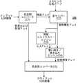
図1は、インプットLDR画像からHDR画像を生成するためのシステム100を示す。図1は、システム・コンポーネント間のデータ・フローを示し、各コンポーネントは、文字「C」で始まり後に番号が続く称号で標識されている。これらシステム・コンポーネントは、以降、C1、C2、…、C5の標記を使って呼ばれる。このシステムは、まず、LDR画像を入力し、それを色空間コンバータC1に送り込むことから作動され、画像は、色相、彩度、および明度の色空間(HSB:Hue、Saturation、Brightness)に変換され、3つの対応するアレイが生成される。明度アレイおよびカメラ・センサ応答カーブが逆マッパーC2に供給される。次いで該マッパーは供給された応答カーブを使って明度アレイを放射輝度アレイに逆マップする。局部コントラスト・エンジンC3は、放射輝度アレイに対する局部的コントラストを計算し、局部輝度平均(LLA:Local Luminance Average)アレイを生成する。覆い焼き/焼き込みエンジンC4は、LLAアレイを使って、放射輝度アレイに覆い焼き/焼き込みを行い、拡大放射輝度アレイを生成する。 FIG. 1 shows a
生成されたアレイは、彩度および色相アレイとともに、色空間コンバータC5に送り込まれ、画像は元のインプットLDRの色空間(例えばRGB)に変換され、アウトプットHDR画像が生成される。 The generated array is sent to the color space converter C5 together with the saturation and hue array, and the image is converted to the color space (eg, RGB) of the original input LDR to generate an output HDR image.
LDR画像に対し逆トーン・マッピングを実施するため、第一フェーズの過程で、インプットLDR画像の輝度は拡大HDR輝度に逆マップされる。この初期ステップは、高輝度の領域でディテールの喪失およびノイズの導入をもたらし、これは、これらの領域を平滑化する第二フェーズの過程で改善される。 In order to perform inverse tone mapping on the LDR image, during the first phase, the luminance of the input LDR image is inverse mapped to the enlarged HDR luminance. This initial step results in loss of detail and the introduction of noise in high brightness areas, which is improved during the second phase of smoothing these areas.
本発明の実施形態によれば、逆トーン・マッピングの第一フェーズは、キャプチャしたセンサ/デバイスの情報を使って実施される。フィルム・カメラと同様、デジタル・カメラを使ってキャプチャされたほとんどの画像に対し、そのセンサの識別は容易に入手可能である。この第一フェーズでは、カメラ応答カーブを使い、インプット画像の逆トーン・マッピングによって初期放射輝度マップが構築される。 According to an embodiment of the present invention, the first phase of inverse tone mapping is performed using the captured sensor / device information. As with film cameras, sensor identification is readily available for most images captured using a digital camera. In this first phase, an initial radiance map is constructed by inverse tone mapping of the input image using the camera response curve.
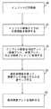
図2は、本発明の実施形態による、この、逆トーン・マッピングの第一フェーズを記述したハイレベルのフローチャートを示す。 FIG. 2 shows a high-level flowchart describing this first phase of inverse tone mapping, according to an embodiment of the present invention.
ステップ20で、最初にLDR画像が入力され、次いでそのLDR画像がメモリ中に格納される。かかるLDR画像は、さまざまな色空間で表現されることができよう。標準的な色空間はRGB空間であり、この色空間では、各ピクセルの色は、3つの成分、すなわち赤(R:Red)、緑(G:Green)、および青(B:Blue)で表現される。別の色空間はLuvであり、このLは輝度成分、uおよびvは各々クロミナンス成分である。逆トーン・マッピングは、輝度チャネル上で実行される。 In
ステップ21において、所与のカメラに対する露光量−ピクセル応答カーブが取得される。露光量−ピクセル応答カーブは各カメラに内在的なもので、センサ・データシートから直接得ることができよう。あるいは、同一光景に対する一連の異なる露光量の画像を解析することによって、露光量−ピクセル応答カーブを算定することもできる。露光量応答カーブは、測定し、計算し、または見積もることができ、あるいは遠隔サイトから入手することすら可能である。このカーブは、カメラごとにほぼ一定であり、しかして、同じカメラによって生成されたさらなる画像に対し応答関数の再構築を繰り返す必要はない。以下の説明において、露光量−ピクセル応答カーブを関数「f(x)」で表すこととし、このxは所与の露光量値を示す。このとき、y=f(x)は、所与の露光量xに対するピクセル輝度値を表すものとする。露光量−ピクセル応答カーブは、対応写真に対する実世界の放射輝度値を提供する。これらの値は、従来技術の単純な逆ガンマ手法を使って得られるものよりも正確である。 In
ステップ22において、LDRインプット画像はHSB色空間アレイに変換され、このHは色相を表し、Sは彩度を表し、Bは明度を表す。HSB(HSL表現としても知られる)は、知覚的色関係をRGBよりも正確に表現する、RGB色モデルにおけるポイント群の表現である以下の説明では、色相アレイを「Hue[ ]」で、彩度アレイを「Saturation[ ]」で、明度アレイを「Brightness[ ]」で表すことにする。 In
ステップ23において、明度アレイ(Brightness[ ])の各ピクセルに対し、応答カーブを使ってその値が逆マップされ、得られた露光量がRadiance(放射輝度)[i]に格納される。露光量―ピクセル応答関数f(x)の逆関数を表すのに「f−1(y)」の表記を使えば、このとき、インプットピクセル値yに対し、f−1(y)は、露光量値xを戻してくる。上記から、チャネル反復子iに対する放射輝度は次式により定義される。
Radiance[i]=f−1(Brightness[i])、
このRadiance[ ]アレイが得られた放射輝度マップである。In
Radiance [i] = f−1 (Brightness [i]),
It is the radiance map from which this Radiance [] array was obtained.
斯く得られた放射輝度マップは、ステップ24においてメモリに格納される。本発明は、カメラの露光量−ピクセル応答カーブを用いて画像の放射輝度マップを再構築することにより、逆ガンマまたは標準の固定的な逆関数に依存する従来の対処技術によって得られるものよりも現実に近い放射輝度マップを提供する。 The radiance map thus obtained is stored in memory in
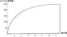
図3は、例示的カメラの応答カーブを示す。「露光量」と題されたx−軸は実世界の露光量値を表し、「ピクセル明度値」と題されたy−軸はカメラによって記録された対応するピクセル放射輝度値を表す。「露光量」は、センサが受光した放射照度に露光時間を乗じた量として定義される。単位は平方メートル当たりワット秒である。ピクセル放射輝度の値は、0〜255の整数を取る一方、露光量値は実数である。 FIG. 3 shows the response curve of an exemplary camera. The x-axis entitled “Exposure” represents the real world exposure value and the y-axis entitled “Pixel Brightness Value” represents the corresponding pixel radiance value recorded by the camera. “Exposure amount” is defined as an amount obtained by multiplying the irradiance received by the sensor by the exposure time. The unit is watt seconds per square meter. The pixel radiance value takes an integer from 0 to 255, while the exposure value is a real number.
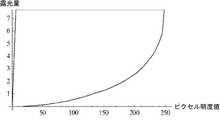
図4は、図3に表された例示的カメラ応答カーブに対する逆応答カーブを示す。「ピクセル明度値」と題されたx−軸はピクセル放射輝度値を指し、「露光量」と題されたy−軸は対応する実世界の露光量値を指す。 FIG. 4 shows the inverse response curve for the exemplary camera response curve represented in FIG. The x-axis entitled “Pixel Brightness Value” refers to the pixel radiance value and the y-axis entitled “Exposure Value” refers to the corresponding real-world exposure value.
この応答カーブは、現実をできるだけ近似して模擬する。この段階で、ステップ24で得られた放射輝度アレイ「Radiance[ ]」を、色相アレイ「Hue[ ]」および彩度アレイ「Saturation[ ]」と組み合わせ、これらを一つの画像に関連付け、次いでその画像を元の画像の色空間に変換してHDR画像を提供することも可能ではあろう。しかしながら、カメラ・カーブが、それ自体で十分な高ダイナミック・レンジを生成できないことがあり、量子化によるアーチファクトを取り込む可能性がある。本発明による逆トーン・マッピングの第二フェーズは、カメラ応答カーブの使用により導入される可能性のあるマッピング円滑性の不十分さおよびアーチファクトを補償する。 This response curve simulates the reality as close as possible. At this stage, the radiance array “Radiance []” obtained in
図5は、本発明の実施形態による、逆トーン・マッピングの第二フェーズを図解する。この第二フェーズの過程では、画像の輝度を選択的に増大または低減させるため、それぞれ覆い焼きおよび焼き込み様の操作が行われる。「覆い焼き」操作は輝度を増大させ、一方「焼き込み」操作はピクセルの輝度を低減させる。本発明は、HDRドメインにおいて覆い焼きおよび焼き込み様の操作を適用し、画像のダイナミック・レンジを拡大する。ハイライト部に対し、覆い焼き操作は、低幅な局部コントラストの領域のダイナミック・レンジをそれ以上に拡大することになろう。陰影部に対しては、焼き込み操作が左側のダイナミック・カーブをもっと拡大し、ピクセルの最小輝度を低下させることになる(これにより画像のダイナミック・レンジはさらに拡大される)。また、これは全般に局部コントラストを拡大し、これにより、LDR画像では見えなかったより多くのディテールが視認可能になる。さらに、HDRドメインに覆い焼きおよび焼き込み様の操作を適用することによって、平滑化が遂行でき、これにより、量子化の影響が低減される。 FIG. 5 illustrates the second phase of inverse tone mapping, according to an embodiment of the present invention. In this second phase process, dodging and burning-like operations are performed to selectively increase or decrease the brightness of the image. “Dodge” operations increase brightness, while “Burn” operations decrease pixel brightness. The present invention applies dodge and burn-like operations in the HDR domain to expand the dynamic range of the image. For highlights, the dodging operation will extend the dynamic range of the low local contrast region beyond that. For shadows, the burn-in operation will expand the left dynamic curve more and lower the minimum brightness of the pixel (this further increases the dynamic range of the image). This also generally increases the local contrast, which allows more details to be seen that were not visible in the LDR image. Furthermore, smoothing can be accomplished by applying dodging and burning-like operations to the HDR domain, thereby reducing the effects of quantization.
ステップ50において、Radiance[ ]アレイ中の各ピクセル(u,v)に対し、局部輝度平均、Local_Luminance_Average[u,v]が計算される。ピクセル(u,v)におけるLocal_Luminance_Averageは、“Erik Reinhard、Michael Stark、Peter Shirley、およびJames Ferwerda著、論文題名「Photographic tone reproduction for digital images」、ACM Trans.Graph.21,3(2002年7月)、267〜276頁”において展開されているアプローチから、以下のように計算することができる。
− 畳み込みカーネルが、kerneli[ ]=GaussianKernel(ガウス・カーネル)(ri)[ ]として設定され、このriはGaussianKernelの半径であり、iは局部コントラストのスケール指標を指す。riの値は変化する。本発明のある特定の実施形態において、この値は1/(2*Sqrt(2))*1.6iに設定される。iの値は、0〜8の範囲で変化する。
− 値iに対するピクセル(u,v)における局部輝度平均は、Local_Luminance_Averagei[u,v]=kerneli Radiance[ ]として計算される。
− 次いで、パラメータiの最小値mが、Abs(Local_Luminance_Averagei[u,v]−Local_Luminance_Averagei+1[u,v])<εにより計算され、このεは閾値を指し、iの値は0〜7の範囲で変化する。
− Local_Luminance_Average[u,v]は最終的にLocalLuminanceAveragem[u,v]に設定され、これによりピクセル(u,v)における局部輝度平均が与えられる。In
- convolution kernelis set as kernel i [] = GaussianKernel (Gaussian kernel)(r i) [], ther i is the radius of GaussianKernel, i refers to the scale indicator of local contrast. The value of ri varies. In certain embodiments of the invention, this value is set to 1 / (2 * Sqrt (2)) * 1.6i . The value of i varies in the range of 0-8.
-The local luminance average at pixel (u, v) for value i is calculated as Local_Luminance_Averagei [u, v] = kerneli Radiance [].
Then the minimum value m of the parameter i is calculated by Abs (Local_Luminance_Averagei [u, v] −Local_Luminance_Averagei + 1 [u, v]) <ε, where ε points to a threshold, i Varies with range.
Local_Luminance_Average [u, v] is finally set to LocalLuminanceAveragem [u, v], which gives the local luminance average at pixel (u, v).
ステップ51において、各ピクセルの輝度は、局部輝度平均Local_Luminance_Average[u,v]を使って調整される。新規の放射輝度値「Radiance’[u,v]」は次式により定義される。
Radiance’[u,v] = Radiance[u,v]*Radiance[u,v]/Local_Luminance_Average[u,v]In
Radiance '[u, v] = Radiance [u, v] * Radiation [u, v] / Local_Luminance_Average [u, v]
本発明によれば、この演算は、HDRドメインにおいて行われる。実際に、本出願人は、ピクセルの周囲(u,v)が原ピクセル(u,v)よりも明度が高い場合、ピクセル(u,v)の放射輝度は低減され、これにより局部コントラストが増大されるのを観察した。同様に、周囲のピクセルの明度が原ピクセルより低い場合、原ピクセル(u,v)の放射輝度が増大され、これにより局部コントラストが増大されることになるのも観察されている。この放射輝度の低減および増大の双方は、Radiance[u,v]/Local_Luminance_Average[u,v]の比率によって設定される。この比率は、放射輝度のスケーリング係数の機能を果たし、圧縮調整なしの任意のスケーリングを可能にする。 According to the present invention, this operation is performed in the HDR domain. In fact, Applicants have found that if the perimeter (u, v) of the pixel is lighter than the original pixel (u, v), the radiance of the pixel (u, v) is reduced, thereby increasing the local contrast. Observed. Similarly, it has also been observed that when the brightness of surrounding pixels is lower than the original pixel, the radiance of the original pixel (u, v) is increased, thereby increasing local contrast. Both reduction and increase in radiance are set by the ratio Radiance [u, v] / Local_Luminance_Average [u, v]. This ratio acts as a radiance scaling factor and allows arbitrary scaling without compression adjustment.
本発明のある実施形態による逆トーン・マッピングの第二フェーズは、従って、覆い焼きおよび焼き込みを介して画像の局部コントラストを高めながら、放射輝度のダイナミック・レンジを増大する。このようにして、本発明は覆い焼き/焼き込みの写真術コンセプトを活用して写真品質のHDR画像を生成する。 The second phase of inverse tone mapping according to an embodiment of the invention thus increases the dynamic range of radiance while increasing the local contrast of the image through dodging and burning. In this manner, the present invention utilizes the dodging / burning photographic concept to generate photographic quality HDR images.
ステップ52において、放射輝度アレイ「Radiance[ ]」は、色相アレイ「Hue[ ]」および彩度アレイ「Saturation[ ]」と組み合わされ、次いでこれらは一つの画像に関連付けられ、次いでステップ53でこの画像は元画像の色空間に変換される。(例えばcimg.sourceforge.orgのcimgライブラリ中のget_RGBtoHSV( )などの)標準的ライブラリ・ルーチンを用い、この画像変換は次式を使って計算され、このConvert( )が画像を元画像色の空間に逆変換する。
Convert(Hue[ ],Saturation[ ],Radiance[ ]/max(Radiance[ ]))*max(Radiance)。In
Convert (Hue [], Saturation [], Radiance [] / max (Radiance [])) * max (Radiance).
通常ピクセル値は0から1の間で変化するように正規化されているので、この式の除算部「Radiance[ ]/max(Radiance[ ])」が使われている。 Since the normal pixel value is normalized so as to change between 0 and 1, the division unit “Radiance [] / max (Radiance [])” of this equation is used.
図6は、本発明の実施形態による、初期放射輝度アレイの例示的ヒストグラムを示し、これは逆トーン・マッピングの第一フェーズだけを使って得られたものである。この放射輝度アレイはインプットLDR画像から生成される。このヒストグラムのx−軸はlog2露光量値を表し、y−軸は発生頻度を表す。図示のように、最大log2露光量は8.3であり最小は−9.38で、これは210,381(5桁)のダイナミック・レンジとなる。これは実世界の通常の光景における典型的な値である。FIG. 6 shows an exemplary histogram of an initial radiance array according to an embodiment of the present invention, which was obtained using only the first phase of inverse tone mapping. This radiance array is generated from the input LDR image. The x-axis of this histogram represents the log2 exposure value, and the y-axis represents the occurrence frequency. As shown, the maximum log2 exposure is 8.3 and the minimum is −9.38, which is a dynamic range of 210,381 (5 digits). This is a typical value in a normal real-world scene.
図7は、本発明の実施形態による、逆トーン・マッピングの第二フェーズ後のヒストグラムを示す。最大のlog2露光量は、これでは8.71であり最小は−15.52で、このダイナミック・レンジは1.98×10⁷である。従って、第二フェーズによってダイナミック・レンジは2桁増大したことになる。また、このヒストグラムがより平滑で、陰影部を強調しながら両側に広く広がっていることは留意に値する。FIG. 7 shows a histogram after the second phase of inverse tone mapping, according to an embodiment of the present invention. The maximum log2 exposure is now 8.71, the minimum is -15.52, and the dynamic range is 1.98 × 10⁷ . Therefore, the dynamic range is increased by two orders of magnitude due to the second phase. It is also worth noting that this histogram is smoother and spreads widely on both sides while emphasizing shadows.
生成されたHDR画像の品質を評定するために、MPI HDR(MPIはMax Planck Institute informatik(マックス・プランク境界情報科学)の頭字語)メトリックを使うことができる。このメトリックは、“T.O.Aydin、R.Mantiuk、K.Myszkowski、およびH.Seidel著、の論文題名「Dynamic range independent image quality assessment」、ACM SIGGRAPH 2008年論文(カリフォルニア州ロサンジェルス、2008年8月11〜15日)SIGGRAPH‘08.ACM,NY、ニューヨーク、1−10”に定義されている。この画像品質メトリックは、両方の画像が任意のダイナミック・レンジを有する画像のペアに対して使われる。このメトリックによれば、青、緑、および赤のピクセルを使って要約画像が生成される。最も高いコントリビュータに応じて各ピクセルに対する色が決定される。青ピクセルは、向上されたコントラストを有するピクセルを表し(インプット画像では見えずアウトプット画像で見える)、緑ピクセルはコントラストの喪失を表し、赤ピクセルはコントラストの逆転を表す。各色の値は、その影響の確率が見えるように表される。本発明人は、メトリックの青および緑パラメータが、画像品質を評定する上で特に重要に見えることに気付いた。実際に、できるだけ緑を低減し青を増加させると、コントラストが向上でき、可視のディテールが喪失されないように見えた。結果として、各ピクセルに対する正規化された優位色の和も観測することによって、画像品質評定の改良が達成された。 To assess the quality of the generated HDR image, the MPI HDR (MPI is an acronym for Max Planck Institute information science) metric can be used. This metric is described in "TOA Aydin, R. Mantiuk, K. Myszkowski, and H. Seidel" title "Dynamic range independent quality quality assessment", ACM SIGGRAPH 2008 2008. 11 to 15th) SIGGRAPH'08. ACM, NY, New York, 1-10 ″. This image quality metric is used for image pairs where both images have an arbitrary dynamic range. According to this metric, blue, A summary image is generated using the green and red pixels, the color for each pixel is determined according to the highest contributor, the blue pixels represent pixels with improved contrast (not visible in the input image) The green pixel represents the loss of contrast, the red pixel represents the contrast reversal, the value of each color is represented so that the probability of its influence is visible. And the green parameter seemed to be particularly important in assessing image quality. Increasing blue, however, appeared to improve contrast and not lose visible detail, resulting in improved image quality rating by observing the sum of normalized dominant colors for each pixel It was done.
図8は、いくつかの画像の比較に基づいて、生成されたHDR画像の品質を評定するために行われるステップを表したフローチャートを示す。後記の実験の理解を容易にするため、後記で、画像の識別に使われる特定の記号の定義を以下に示す。
1− 「Real−HDR」は、露光を変えた画像の大きなシーケンスを使って得られた画像を指す。言い換えれば「現実の」HDR画像である。
2− 「Input−LDR」はインプットLDR画像を指す。
3− 「Gen−HDR」は、Input−LDR画像を逆処理して得られた、生成HDR画像を指す。
4− 「Gen−LDR」は、Reinhardらの写真トーン・マッピング演算子(Erik Reinhard、Michael Stark、Peter Shirley、およびJames Ferwerda著、論文題名「Photographic tone reproduction for digital images」、SIGGRAPH’02:Computer Graphics and Interactive Techniques第29回年度協議会抄録、267〜276頁、米国NY州ニューヨーク、2002年。ACM Press)を使って得られた、トーン・マップされたGen−HDRを指す。
5− 「Gen−HDR−Rad」は、本発明による、逆トーン・マッピングの第一フェーズだけを使った、生成HDR画像を指す。FIG. 8 shows a flowchart representing the steps taken to assess the quality of the generated HDR image based on a comparison of several images. In order to facilitate understanding of the experiments described below, the definitions of specific symbols used for image identification are given below.
1— “Real-HDR” refers to an image obtained using a large sequence of images with different exposures. In other words, it is a “real” HDR image.
2- “Input-LDR” refers to the input LDR image.
3- “Gen-HDR” refers to a generated HDR image obtained by inversely processing an Input-LDR image.
4- “Gen-LDR” is a photo-tone mapping operator by Reinhard et al. and Interactive Technologies, 29th Annual Meeting Abstract, pp. 267-276, New York, NY, 2002, ACM Press), refers to tone-mapped Gen-HDR.
5- “Gen-HDR-Rad” refers to a generated HDR image using only the first phase of inverse tone mapping according to the present invention.
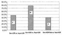
以下の図8の説明は、上記で定義された画像1〜5を比較することによって得られた青/緑ピクセルの和の値を示す、図9および10を参照しながらこれらの説明と併せ行うこととする。図9は、右側2列が各々の比較に対する青と緑との値を表している表であり、図10は、各比較に対するピクセル当たりのコントラスト・ゲイン(正規化された青ピクセルの和)を表した図である。本発明の実施形態による、逆トーン・マッピング各フェーズの、生成HDR画像の品質における影響を評定するために、最初にステップ80において、Gen−HDR−RadとReal−HDRとが比較される。この最初の比較は、本発明による、逆トーン・マッピングの第一フェーズ適用の影響を評定する。得られた結果のAが図9および10に示されている。この結果は、40.0%の大幅なピクセル当たりコントラスト・ゲイン、および0.1%のごくわずかなコントラスト喪失があることを表している。 The following description of FIG. 8 is combined with these descriptions with reference to FIGS. 9 and 10, which show the value of the sum of blue / green pixels obtained by comparing images 1-5 as defined above. I will do it. FIG. 9 is a table in which the right two columns represent the blue and green values for each comparison, and FIG. 10 shows the contrast gain per pixel (normalized sum of blue pixels) for each comparison. FIG. Gen-HDR-Rad and Real-HDR are first compared at
本発明による、逆トーン・マッピングの第二フェーズ適用の影響を評定するために、ステップ81において、Gen−HDRとReal−HDRとの比較が行われる。得られた結果Bは、図9および10に示され、77.4%のずっと大きなピクセル当たりコントラスト・ゲインおよび0.0%に近い無視可能なコントラスト喪失を表している。これは、第二フェーズが、コントラスト・ゲインに37%のさらなる増大を効果的に加えたことを示している。 In order to assess the impact of applying the second phase of inverse tone mapping according to the present invention, a comparison between Gen-HDR and Real-HDR is performed in
HDR画像の典型的な用途の一つはLDR画像の品質の向上なので、ステップ82では、Gen−LDRとInput−LDRとを比較することによってその影響を検証する。得られた結果Cは、図9および10に表され、大幅なコントラスト・ゲインの向上が示されており、これでは47.2%のゲインでコントラストの喪失はない。これによれば、HDRに変換する際に元画像のディテールの喪失はない。これに加えて、生成HDRは、元画像では見えなかったディテールも包含している。この後者の結果は、例えば医療画像分割などの画像改良アプリケーションの助力となり得るであろう。 One of the typical uses of HDR images is to improve the quality of LDR images, so in
本発明は、例えば、既存のLDRビデオおよび画像ライブラリを、新規のHDRディスプレイに用いるためのHDRビデオおよび画像に変換するアプリケーションなど、多くの画像処理アプリケーションに応用することができよう。また、本発明は、LDR画像の改善にも適用でき、LDR画像はまずHDR画像に変換され、次いで(平滑化、エッジ検出などの)標準的な画像処理による改善が適用され、しかる後、(Reinhardのトーン・マッピング演算子などの)標準的トーン・マッピング技法を使って、HDR画像からLDRに戻し変換が行われる。 The present invention could be applied to many image processing applications, for example, applications that convert existing LDR video and image libraries into HDR video and images for use in new HDR displays. The present invention can also be applied to the improvement of LDR images, where the LDR image is first converted to an HDR image, then standard image processing improvements (such as smoothing, edge detection, etc.) are applied and then ( Conversion from the HDR image back to LDR is performed using standard tone mapping techniques (such as Reinhard's tone mapping operator).
斯くのごとく、本発明は単一のLDR画像からHDR値を再生するための効率的な技法を提供する。 As such, the present invention provides an efficient technique for reproducing HDR values from a single LDR image.
従来の対処技術は高輝度部分だけの拡大なのに対し、本発明では、ダイナミック・レンジは、輝度チャネルの両方のテール(高輝度および低輝度部分)から拡大される。これは、画像の中間部/陰影部に亘っての視認可能なディテールのレベルを増加させる。これは、画像のダイナミック・レンジを、従来技術によるものよりさらに増大する。 Whereas the traditional coping technique is to enlarge only the high luminance part, in the present invention, the dynamic range is extended from both tails (high and low luminance parts) of the luminance channel. This increases the level of visible detail across the middle / shaded part of the image. This further increases the dynamic range of the image than with the prior art.
逆トーン・マッピングの第一フェーズで、カメラの露光量−ピクセル・カーブを使用することによって、画像のより現実に近い放射輝度が提供され、仕上がり画像の観賞品質が向上される。 Using the camera exposure-pixel curve in the first phase of inverse tone mapping provides a more realistic radiance of the image and improves the viewing quality of the finished image.
本発明によって、医療画像化など多くのアプリケーションにおいて、最新のHDRディスプレイを使って既存のLDR画像を見ることができる。 The present invention allows existing LDR images to be viewed using modern HDR displays in many applications such as medical imaging.
さらに、本発明の実施形態による逆トーン・マッピングを用い、より高品質のHDR画像を生成してそれを順方向トーン・マップしてLDRに戻すことによって、LDRカメラのアウトプットの品質を向上することができ、これによりコントラストの可視性の大幅な改善が実現できる。その結果として、さらなる処理作業のためのエッジの検出を簡素化することができる。 Furthermore, using the inverse tone mapping according to embodiments of the present invention, the quality of the output of the LDR camera is improved by generating a higher quality HDR image and forward mapping it to the LDR. This can provide a significant improvement in contrast visibility. As a result, edge detection for further processing operations can be simplified.
本発明は多くのアプリケーションを有する。例えば、医療画像化におけるエッジ検出などのさらなる画像処理でのHDRドメインにおける作業の改良など、デジタル画像に対する向上されたオペレーションとして本発明を用いることができる。 The present invention has many applications. The present invention can be used as an enhanced operation on digital images, such as, for example, improving work in the HDR domain with further image processing such as edge detection in medical imaging.
さらに一般的に言えば、本発明は、低品質の音声信号のダイナミック・レンジの増大など、任意のデジタル信号に適用できる。 More generally, the present invention can be applied to any digital signal, such as increasing the dynamic range of a low quality audio signal.
図11は、本発明の実施形態による、ビデオ画像をLDR画像からHDR画像に変換するため使われるコンピュータ・システム90を示す。コンピュータ・システム90は、プロセッサ91と、プロセッサ91に連結された入力デバイス92と、プロセッサ91に連結された出力デバイス93と、各々がプロセッサ91連結されたメモリ・デバイス94および95とを含む。プロセッサ91は、中央処理装置(CPU)などの処理装置である。入力デバイス92は、とりわけ、キーボード、マウスなどとすることができる。出力デバイス93は、とりわけ、プリンタ、プロッタ、ディスプレイ・デバイス(例えばコンピュータ・スクリーン)、磁気テープ、着脱可能ハード・ディスク、フレキシブル・ディスクなどとすることができる。このディスプレイ・デバイスには、図1の100のディスプレイ領域を含めることができる。メモリ・デバイス94および95は、とりわけ、ハード・ディスク、フレキシブル・ディスク、磁気テープ、コンパクト・ディスク(CD:compact disc)またはデジタル・ビデオ・ディスク(DVD:digital video disc)などの光記憶デバイス、ダイナミック・ランダム・アクセス・メモリ(DRAM:dynamic random access memory)、読み取り専用メモリ(ROM:read−only memory)などとすることができる。メモリ・デバイス95は、コンピュータ実行可能命令を含むコンピュータ・プログラムである、コンピュータ・コード97を包含する。コンピュータ・コード97は、ビデオ画像をLDR画像からHDR画像に変換するためのアルゴリズムを包含する。プロセッサ91はコンピュータ・コード97を実行する。メモリ・デバイス94はインプット・データ96を包含する。インプット・データ96は、コンピュータ・コード97に要求されるインプットを包含する。出力デバイス93は、コンピュータ・コード97からのアウトプットを表示する。メモリ・デバイス94および95(または図11に示されていない一つ以上の追加のメモリ・デバイス)のいずれかまたは両方は、中に具現されたコンピュータ可読プログラムを有する、もしくはその中に格納された他のデータを有する、またはその両方を有するコンピュータ可用記憶媒体(またはプログラム記憶デバイス)として用いることができ、このコンピュータ可読プログラムはコンピュータ・コード97を含む。一般に、コンピュータ・システム90のコンピュータ・プログラム製品(あるいは、製造品)は、上記コンピュータ可用記憶媒体(または上記プログラム記憶デバイス)を含み得る。 FIG. 11 shows a
図11は、コンピュータ・システム90をハードウエアおよびソフトウエアの特定の構成として示しているが、当業者なら周知のように、前述の目的のために、図11の特定のコンピュータ・システム90と組み合わせて、ハードウエアおよびソフトウエアの任意の構成を用いることができる。例えば、メモリ・デバイス94と95とを、別個のメモリ・デバイスでなく単一のメモリ・デバイスの部分とすることもできる。 FIG. 11 illustrates
本明細書では、例示説明を目的として本発明の特定の実施形態を説明してきたが、当業者には多くの変更および変形が明白になっていよう。 While specific embodiments of the present invention have been described herein for purposes of illustration, many modifications and changes will become apparent to those skilled in the art.
Claims (10)
Translated fromJapanese− 前記所与のカメラに対する露光量−ピクセル応答カーブを取得するステップ(21)と、
− 前記LDR画像をHSB色空間アレイに変換するステップ(22)であって、前記HSB色空間アレイは、色相アレイ、彩度アレイ、および明度アレイを含む、前記変換するステップと、
− 前記露光量−ピクセル応答カーブの逆関数を使って、前記明度アレイ中の各ピクセルを逆マッピングすることによって放射輝度アレイを算定するステップ(23、24)と、
− 前記放射輝度アレイ中の各ピクセルに対し局部輝度平均を算定し(50)、前記ピクセルに対する前記放射輝度アレイの値と前記局部輝度平均とから、各ピクセルに対する調整された放射輝度アレイを計算するステップ(51)と、
− 前記放射輝度アレイを、前記HSB色空間アレイの前記色相および彩度アレイと組み合わせるステップ(52)と、
− 前記画像を、前記色相、彩度、および放射輝度アレイを使い画像色空間に変換し、前記HDR画像を提供するステップ(53)と、
を含む方法。A method for converting a digital image from a low dynamic range (LDR) image obtained using a given camera to a high dynamic range (HDR) image, the method comprising:
Obtaining an exposure-pixel response curve for the given camera;
-Converting (22) the LDR image into an HSB color space array, wherein the HSB color space array comprises a hue array, a saturation array, and a lightness array;
Calculating (23, 24) a radiance array by inverse mapping each pixel in the brightness array using an inverse function of the exposure-pixel response curve;
Calculating (50) a local luminance average for each pixel in the radiance array and calculating an adjusted radiance array for each pixel from the value of the radiance array for the pixel and the local luminance average. Step (51);
-Combining the radiance array with the hue and saturation array of the HSBcolor space array (52);
Converting the image into an image color space using the hue, saturation, and radiance array to provide the HDR image;
Including methods.
Radiance’[u,v] = Radiance[u,v]*Radiance[u,v]/Local_Luminance_Average[u,v]、
Radiance[u,v]は、ピクセル(u,v)に対する前記放射輝度の値を指し、Local_Luminance_Average[u,v]は、ピクセル(u,v)における前記局部輝度平均を指す、請求項1〜3のいずれかに記載の方法。For each pixel (u, v), the adjusted radiance Radiance '[u, v] is calculated by the following equation:
Radiance '[u, v] = Radiance [u, v] * Radiance [u, v] / Local_Luminance_Average [u, v],
Radiance [u, v] refers to the radiance value for pixel (u, v), and Local_Luminance_Average [u, v] refers to the local luminance average at pixel (u, v). The method in any one of.
Convert(Hue[ ],Saturation[ ],Radiance[ ]/max(Radiance[ ]))*max(Radiance)、
Hue[ ]は前記色相アレイを、Saturation[ ]は前記彩度アレイを、Radiance[ ]は前記放射輝度アレイを指す、請求項1〜4のいずれかに記載の方法。The step of converting the image to the image color space is performed by the following equation:
Convert (Hue [], Saturation [], Radiance [] / max (Radiance [])) * max (Radiance),
The method according to claim 1, wherein Hue [] refers to the hue array, Saturation [] refers to the saturation array, and Radiance [] refers to the radiance array.
kerneli[ ]=GaussianKernel(ri)[ ]、
riはGaussianKernelの半径であり、iは0〜8の間で変化する局部コントラストのスケール指標である、請求項1〜5のいずれかに記載の方法。The local luminance average is calculated from an i-convolution kernel defined by:
kernel i [] = GaussianKernel (r i) [],
ri is the radius of GaussianKernel, i is a scale indication of local contrast varying between 0-8, the method according to any one of claims 1 to 5.
− 前記所与のカメラに対する露光量−ピクセル応答カーブを取得するステップ(21)と、
− 前記LDR画像をHSB色空間アレイに変換するステップ(22)であって、前記HSB色空間アレイは、色相アレイ、彩度アレイ、および明度アレイを含む、前記変換するステップと、
− 前記露光量−ピクセル応答カーブの逆関数を使って、前記明度アレイ中の各ピクセルを逆マッピングすることによって放射輝度アレイを算定するステップ(23、24)と、
− 前記放射輝度アレイ中の各ピクセルに対し局部輝度平均を算定し(50)、前記ピクセルに対する前記放射輝度アレイの値と前記局部輝度平均とから、各ピクセルに対する調整された放射輝度アレイを計算するステップ(51)と、
− 前記放射輝度アレイを、前記HSB色空間アレイの前記色相および彩度アレイと組み合わせるステップ(52)と、
− 前記画像を、前記色相、彩度、および放射輝度アレイを使い画像色空間に変換し、前記HDR画像を提供するステップ(53)と、
を実行する、システム。A system for converting a digital image from a low dynamic range (LDR) image obtained using a given camera to a high dynamic range (HDR) image, the system comprising:
Obtaining an exposure-pixel response curve for the given camera;
-Converting (22) the LDR image into an HSB color space array, wherein the HSB color space array comprises a hue array, a saturation array, and a lightness array;
Calculating (23, 24) a radiance array by inverse mapping each pixel in the brightness array using an inverse function of the exposure-pixel response curve;
Calculating (50) a local luminance average for each pixel in the radiance array and calculating an adjusted radiance array for each pixel from the value of the radiance array for the pixel and the local luminance average. Step (51);
-Combining the radiance array with the hue and saturation array of the HSBcolor space array (52);
Converting the image into an image color space using the hue, saturation, and radiance array to provide the HDR image;
Run the system.
Applications Claiming Priority (3)
| Application Number | Priority Date | Filing Date | Title |
|---|---|---|---|
| EP09172538.2 | 2009-10-08 | ||
| EP09172538 | 2009-10-08 | ||
| PCT/EP2010/059950WO2011042229A1 (en) | 2009-10-08 | 2010-07-12 | Method and system for transforming a digital image from a low dynamic range (ldr) image to a high dynamic range (hdr) image |
Publications (2)
| Publication Number | Publication Date |
|---|---|
| JP2013507674A JP2013507674A (en) | 2013-03-04 |
| JP5752133B2true JP5752133B2 (en) | 2015-07-22 |
Family
ID=42668680
Family Applications (1)
| Application Number | Title | Priority Date | Filing Date |
|---|---|---|---|
| JP2012532506AActiveJP5752133B2 (en) | 2009-10-08 | 2010-07-12 | Method and system for converting a digital image from a low dynamic range (LDR) image to a high dynamic range (HDR) image |
Country Status (7)
| Country | Link |
|---|---|
| US (1) | US9020257B2 (en) |
| JP (1) | JP5752133B2 (en) |
| CN (1) | CN102696220A (en) |
| DE (1) | DE112010003988B4 (en) |
| GB (1) | GB2486348B (en) |
| TW (1) | TW201138481A (en) |
| WO (1) | WO2011042229A1 (en) |
Families Citing this family (84)
| Publication number | Priority date | Publication date | Assignee | Title |
|---|---|---|---|---|
| US8897524B2 (en)* | 2007-10-29 | 2014-11-25 | Ramot At Tel-Aviv University Ltd. | Method and device for processing computerized tomography images |
| US8648942B2 (en)* | 2007-12-20 | 2014-02-11 | Ramot At Tel-Aviv University Ltd. | Method of and apparatus for processing images using saturation functions |
| JP5752133B2 (en) | 2009-10-08 | 2015-07-22 | インターナショナル・ビジネス・マシーンズ・コーポレーションInternational Business Machines Corporation | Method and system for converting a digital image from a low dynamic range (LDR) image to a high dynamic range (HDR) image |
| EP2601636A1 (en) | 2010-08-05 | 2013-06-12 | Ramot at Tel Aviv University, Ltd. | Method and system for processing an image featuring multiple scales |
| US9368087B2 (en)* | 2010-08-31 | 2016-06-14 | Dolby Laboratories Licensing Corporation | Display backlight normalization |
| JP5803233B2 (en)* | 2011-02-14 | 2015-11-04 | 株式会社リコー | Imaging apparatus and imaging method |
| US9886552B2 (en) | 2011-08-12 | 2018-02-06 | Help Lighting, Inc. | System and method for image registration of multiple video streams |
| CN103907343B (en) | 2011-10-20 | 2017-05-03 | 杜比实验室特许公司 | method and system for video equalization |
| US9020203B2 (en) | 2012-05-21 | 2015-04-28 | Vipaar, Llc | System and method for managing spatiotemporal uncertainty |
| CN102779334B (en)* | 2012-07-20 | 2015-01-07 | 华为技术有限公司 | Correction method and device of multi-exposure motion image |
| US9406028B2 (en)* | 2012-08-31 | 2016-08-02 | Christian Humann | Expert system for prediction of changes to local environment |
| US8446481B1 (en) | 2012-09-11 | 2013-05-21 | Google Inc. | Interleaved capture for high dynamic range image acquisition and synthesis |
| BR112015005153A2 (en)* | 2012-09-12 | 2017-07-04 | Koninklijke Philips Nv | image processing apparatus, predefined mapping algorithm data delivery server, method of obtaining a first lumen image (hdr_pred) for a first luminance dynamic range from the second lumen image (ldr_cont) to a second range luminance dynamics and predefined mapping algorithm (gam, gam_enc) data provisioning method to transform a graduated second image (ldr_cont) for rendering into a second luminance dynamic range display |
| US8995783B2 (en) | 2012-09-19 | 2015-03-31 | Qualcomm Incorporation | System for photograph enhancement by user controlled local image enhancement |
| CN104364820B (en)* | 2012-10-08 | 2018-04-10 | 皇家飞利浦有限公司 | Brightness with color constraint changes image procossing |
| US9679365B2 (en)* | 2012-11-16 | 2017-06-13 | Thomson Licensing | Processing high dynamic range images |
| US8866927B2 (en) | 2012-12-13 | 2014-10-21 | Google Inc. | Determining an image capture payload burst structure based on a metering image capture sweep |
| US9087391B2 (en) | 2012-12-13 | 2015-07-21 | Google Inc. | Determining an image capture payload burst structure |
| US8866928B2 (en) | 2012-12-18 | 2014-10-21 | Google Inc. | Determining exposure times using split paxels |
| US9247152B2 (en) | 2012-12-20 | 2016-01-26 | Google Inc. | Determining image alignment failure |
| US9710968B2 (en)* | 2012-12-26 | 2017-07-18 | Help Lightning, Inc. | System and method for role-switching in multi-reality environments |
| CN103905738B (en)* | 2012-12-31 | 2018-12-21 | 博世汽车部件(苏州)有限公司 | High dynamic range images generate system and method |
| US8995784B2 (en) | 2013-01-17 | 2015-03-31 | Google Inc. | Structure descriptors for image processing |
| US9686537B2 (en) | 2013-02-05 | 2017-06-20 | Google Inc. | Noise models for image processing |
| RU2633128C2 (en)* | 2013-02-21 | 2017-10-11 | Конинклейке Филипс Н.В. | Improved methods and devices for coding and decoding hdr images |
| US9117134B1 (en) | 2013-03-19 | 2015-08-25 | Google Inc. | Image merging with blending |
| US9066017B2 (en) | 2013-03-25 | 2015-06-23 | Google Inc. | Viewfinder display based on metering images |
| US9077913B2 (en) | 2013-05-24 | 2015-07-07 | Google Inc. | Simulating high dynamic range imaging with virtual long-exposure images |
| US9131201B1 (en) | 2013-05-24 | 2015-09-08 | Google Inc. | Color correcting virtual long exposures with true long exposures |
| US9940750B2 (en) | 2013-06-27 | 2018-04-10 | Help Lighting, Inc. | System and method for role negotiation in multi-reality environments |
| US9615012B2 (en) | 2013-09-30 | 2017-04-04 | Google Inc. | Using a second camera to adjust settings of first camera |
| WO2015061335A2 (en) | 2013-10-22 | 2015-04-30 | Dolby Laboratories Licensing Corporation | Guided color grading for extended dynamic range |
| EP3070934A4 (en)* | 2013-11-13 | 2017-03-29 | LG Electronics Inc. | Broadcast signal transmission method and apparatus for providing hdr broadcast service |
| CN105745914B (en)* | 2013-11-22 | 2018-09-07 | 杜比实验室特许公司 | Method and system for inverse tone mapping |
| JP6461165B2 (en)* | 2013-12-27 | 2019-01-30 | トムソン ライセンシングThomson Licensing | Method of inverse tone mapping of image |
| KR102077435B1 (en) | 2014-02-07 | 2020-02-13 | 소니 주식회사 | Transmission device, transmission method, reception device, reception method, display device, and display method |
| US9973723B2 (en)* | 2014-02-24 | 2018-05-15 | Apple Inc. | User interface and graphics composition with high dynamic range video |
| EP2927865A1 (en)* | 2014-04-01 | 2015-10-07 | Thomson Licensing | Method and apparatus for encoding and decoding HDR images |
| KR20220025153A (en)* | 2014-02-26 | 2022-03-03 | 인터디지털 브이씨 홀딩스 인코포레이티드 | Method and apparatus for encoding and decoding hdr images |
| JP6278193B2 (en)* | 2014-04-30 | 2018-02-14 | コニカミノルタ株式会社 | HDR image generation program, apparatus and method thereof |
| CN110231926B (en)* | 2014-06-10 | 2022-11-04 | 松下知识产权经营株式会社 | Reproducing method and reproducing apparatus |
| KR102445762B1 (en)* | 2014-06-25 | 2022-09-22 | 인터디지털 매디슨 페턴트 홀딩스 에스에이에스 | Method and device for processing images |
| CN104320598B (en)* | 2014-11-06 | 2017-09-26 | 中国科学院光电研究院 | A kind of aberration free image reconstructing method demarcated based on ccd array pixel response function frequency domain |
| US20180005357A1 (en)* | 2015-01-30 | 2018-01-04 | Thomson Licensing | Method and device for mapping a hdr picture to a sdr picture and corresponding sdr to hdr mapping method and device |
| EP3051488A1 (en)* | 2015-01-30 | 2016-08-03 | Thomson Licensing | A method and apparatus for inverse-tone mapping a picture |
| JP2016163052A (en)* | 2015-02-26 | 2016-09-05 | オリンパス株式会社 | Image processing apparatus, imaging device, image processing method, and image processing program |
| US20160286241A1 (en)* | 2015-03-24 | 2016-09-29 | Nokia Technologies Oy | Apparatus, a method and a computer program for video coding and decoding |
| KR20160138685A (en)* | 2015-05-26 | 2016-12-06 | 에스케이하이닉스 주식회사 | Apparatus For Generating Low Complexity High Dynamic Range Image, and Method Thereof |
| US10108213B2 (en) | 2015-06-16 | 2018-10-23 | The Hong Kong University Of Science And Technology | Three-dimensional power stage and adaptive pipeline control |
| EP3131284A1 (en)* | 2015-08-13 | 2017-02-15 | Thomson Licensing | Methods, systems and aparatus for hdr to hdr inverse tone mapping |
| WO2017030311A1 (en)* | 2015-08-19 | 2017-02-23 | 삼성전자 주식회사 | Electronic device performing image conversion, and method thereof |
| WO2017036908A1 (en)* | 2015-08-31 | 2017-03-09 | Thomson Licensing | Method and apparatus for inverse tone mapping |
| EP3364654B1 (en) | 2015-12-15 | 2021-03-03 | Huawei Technologies Co., Ltd. | High dynamic range image processing method and apparatus |
| US9697592B1 (en)* | 2015-12-30 | 2017-07-04 | TCL Research America Inc. | Computational-complexity adaptive method and system for transferring low dynamic range image to high dynamic range image |
| US10750173B2 (en)* | 2016-03-07 | 2020-08-18 | Koninklijke Philips N.V. | Encoding and decoding HDR videos |
| US10699391B2 (en) | 2016-04-29 | 2020-06-30 | Disney Enterprises, Inc. | Dynamic range expansion highlight information restoration |
| EP3249605A1 (en)* | 2016-05-23 | 2017-11-29 | Thomson Licensing | Inverse tone mapping method and corresponding device |
| KR102552747B1 (en)* | 2016-06-28 | 2023-07-11 | 주식회사 엘엑스세미콘 | Inverse tone mapping method |
| US10062152B2 (en) | 2016-07-27 | 2018-08-28 | Sharp Laboratories Of America, Inc. | System for conversion of low dynamic range images to high dynamic range images |
| EP3312798A1 (en)* | 2016-10-20 | 2018-04-25 | Thomson Licensing | Method and device for inverse tone mapping |
| AU2016427777B2 (en)* | 2016-10-31 | 2022-12-15 | Victoria Link Limited | A rendering process and system |
| US10187584B2 (en) | 2016-12-20 | 2019-01-22 | Microsoft Technology Licensing, Llc | Dynamic range extension to produce high dynamic range images |
| EP3373585A1 (en)* | 2017-03-09 | 2018-09-12 | Thomson Licensing | Method for inverse tone mapping of an image with visual effects |
| CN107483844B (en)* | 2017-09-04 | 2020-08-25 | 海信视像科技股份有限公司 | Image processing method and device |
| KR101957850B1 (en)* | 2017-12-01 | 2019-03-13 | 가톨릭대학교 산학협력단 | Apparatus and method for reverse tone mapping using guided filter |
| EP3503019A1 (en)* | 2017-12-21 | 2019-06-26 | Thomson Licensing | Improved inverse tone mapping method and corresponding device |
| KR102460390B1 (en)* | 2018-01-24 | 2022-10-28 | 삼성전자주식회사 | Image processing apparatus, method for processing image and computer-readable recording medium |
| KR102524671B1 (en)* | 2018-01-24 | 2023-04-24 | 삼성전자주식회사 | Electronic apparatus and controlling method of thereof |
| US10715774B2 (en) | 2018-07-23 | 2020-07-14 | Microsoft Technology Licensing, Llc | Color conversion for ambient-adaptive digital content |
| KR102127760B1 (en)* | 2018-11-30 | 2020-06-29 | 고려대학교 산학협력단 | Device and method for inverse tone mapping using a single low dynamic range image, recording medium for performing the method |
| CN109785263B (en)* | 2019-01-14 | 2022-09-16 | 北京大学深圳研究生院 | A Retinex-based Inverse Tone Mapping Image Conversion Method |
| CN110009574B (en)* | 2019-02-13 | 2023-01-17 | 中山大学 | A method for inversely generating high dynamic range images from low dynamic range images |
| US11355049B2 (en)* | 2019-09-26 | 2022-06-07 | Apple, Inc. | Pixel leakage and internal resistance compensation systems and methods |
| CN110910347B (en)* | 2019-10-18 | 2023-06-06 | 宁波大学 | A No-Reference Quality Assessment Method for Tone Mapping Images Based on Image Segmentation |
| CN111709900A (en)* | 2019-10-21 | 2020-09-25 | 上海大学 | A High Dynamic Range Image Reconstruction Method Based on Global Feature Guidance |
| CN111242883B (en)* | 2020-01-10 | 2023-03-28 | 西安电子科技大学 | Dynamic scene HDR reconstruction method based on deep learning |
| CN113395459A (en)* | 2020-03-13 | 2021-09-14 | 西安诺瓦星云科技股份有限公司 | Dynamic range adjusting system and method |
| US12368964B2 (en) | 2020-04-03 | 2025-07-22 | Dolby Laboratories Licensing Corporation | Blind local reshaping in HDR imaging |
| US11662810B2 (en) | 2020-06-05 | 2023-05-30 | Magic Leap, Inc. | Enhanced eye tracking techniques based on neural network analysis of images |
| US11544827B2 (en)* | 2021-04-30 | 2023-01-03 | Realnetworks, Inc. | Hue-based video enhancement and rendering |
| US11595589B2 (en) | 2021-07-22 | 2023-02-28 | Arthrex, Inc. | Surgical camera system with high dynamic range |
| KR20230065055A (en) | 2021-11-04 | 2023-05-11 | 삼성전자주식회사 | Image sensor |
| CN116740256A (en) | 2022-03-03 | 2023-09-12 | 腾讯科技(成都)有限公司 | Image rendering method, device, electronic equipment, storage medium and program product |
| CN116567397A (en)* | 2023-05-06 | 2023-08-08 | 北京经纬恒润科技股份有限公司 | Image processing method and device |
Family Cites Families (18)
| Publication number | Priority date | Publication date | Assignee | Title |
|---|---|---|---|---|
| US5828793A (en)* | 1996-05-06 | 1998-10-27 | Massachusetts Institute Of Technology | Method and apparatus for producing digital images having extended dynamic ranges |
| US6864916B1 (en) | 1999-06-04 | 2005-03-08 | The Trustees Of Columbia University In The City Of New York | Apparatus and method for high dynamic range imaging using spatially varying exposures |
| US6687400B1 (en) | 1999-06-16 | 2004-02-03 | Microsoft Corporation | System and process for improving the uniformity of the exposure and tone of a digital image |
| US6650774B1 (en) | 1999-10-01 | 2003-11-18 | Microsoft Corporation | Locally adapted histogram equalization |
| US7298402B2 (en)* | 2000-10-26 | 2007-11-20 | Olympus Corporation | Image-pickup apparatus with expanded dynamic range capabilities |
| US7120293B2 (en) | 2001-11-30 | 2006-10-10 | Microsoft Corporation | Interactive images |
| US7430011B2 (en)* | 2003-01-22 | 2008-09-30 | Omnivision Technologies, Inc. | Image sensor having dual automatic exposure control |
| US7142723B2 (en) | 2003-07-18 | 2006-11-28 | Microsoft Corporation | System and process for generating high dynamic range images from multiple exposures of a moving scene |
| US20050243176A1 (en)* | 2004-04-30 | 2005-11-03 | James Wu | Method of HDR image processing and manipulation |
| TWI246031B (en)* | 2004-09-17 | 2005-12-21 | Ulead Systems Inc | System and method for synthesizing multi-exposed image |
| JP4766302B2 (en) | 2005-03-22 | 2011-09-07 | オムロン株式会社 | Image processing apparatus and method, recording medium, and program |
| US7426312B2 (en) | 2005-07-05 | 2008-09-16 | Xerox Corporation | Contrast enhancement of images |
| TW200820123A (en)* | 2006-10-20 | 2008-05-01 | Primax Electronics Ltd | Method and system of generating high dynamic range image corresponding to specific scene |
| KR101466596B1 (en) | 2006-11-27 | 2014-11-28 | 돌비 레버러토리즈 라이쎈싱 코오포레이션 | Apparatus and methods for boosting dynamic range in digital images |
| JP5188101B2 (en)* | 2007-06-01 | 2013-04-24 | 株式会社キーエンス | Magnification observation apparatus, magnified image photographing method, magnified image photographing program, and computer-readable recording medium |
| JP2009049547A (en) | 2007-08-15 | 2009-03-05 | Seiko Epson Corp | Image processing apparatus, image processing method, and image processing program |
| US8237813B2 (en)* | 2009-04-23 | 2012-08-07 | Csr Technology Inc. | Multiple exposure high dynamic range image capture |
| JP5752133B2 (en) | 2009-10-08 | 2015-07-22 | インターナショナル・ビジネス・マシーンズ・コーポレーションInternational Business Machines Corporation | Method and system for converting a digital image from a low dynamic range (LDR) image to a high dynamic range (HDR) image |
- 2010
- 2010-07-12JPJP2012532506Apatent/JP5752133B2/enactiveActive
- 2010-07-12WOPCT/EP2010/059950patent/WO2011042229A1/enactiveApplication Filing
- 2010-07-12DEDE112010003988.7Tpatent/DE112010003988B4/enactiveActive
- 2010-07-12CNCN2010800444110Apatent/CN102696220A/enactivePending
- 2010-07-12USUS13/500,926patent/US9020257B2/enactiveActive
- 2010-07-12GBGB1121761.9Apatent/GB2486348B/enactiveActive
- 2010-08-31TWTW099129363Apatent/TW201138481A/enunknown
Also Published As
| Publication number | Publication date |
|---|---|
| GB2486348A (en) | 2012-06-13 |
| TW201138481A (en) | 2011-11-01 |
| DE112010003988B4 (en) | 2016-05-12 |
| WO2011042229A1 (en) | 2011-04-14 |
| JP2013507674A (en) | 2013-03-04 |
| US20120201456A1 (en) | 2012-08-09 |
| DE112010003988T5 (en) | 2013-01-17 |
| GB2486348B (en) | 2014-11-12 |
| US9020257B2 (en) | 2015-04-28 |
| CN102696220A (en) | 2012-09-26 |
| GB201121761D0 (en) | 2012-02-01 |
Similar Documents
| Publication | Publication Date | Title |
|---|---|---|
| JP5752133B2 (en) | Method and system for converting a digital image from a low dynamic range (LDR) image to a high dynamic range (HDR) image | |
| Shen et al. | Exposure fusion using boosting Laplacian pyramid. | |
| JP5411706B2 (en) | Apparatus and method for enhancing the dynamic range of digital images | |
| JP4429103B2 (en) | System and method for generating high dynamic range images | |
| US7283666B2 (en) | Digital image exposure correction | |
| KR102567860B1 (en) | Improved inverse tone mapping method and corresponding device | |
| WO2022000397A1 (en) | Low-illumination image enhancement method and apparatus, and computer device | |
| Boitard et al. | Temporal coherency for video tone mapping | |
| JP2018527675A (en) | Inverse tone mapping method and apparatus | |
| CN106056629A (en) | High dynamic range imaging method for removing ghosts through moving object detection and extension | |
| JP2004030670A (en) | Enhancement method for color tone feature of digital image | |
| JP2010062672A (en) | Image processor and method thereof | |
| JP2002300402A (en) | Image processor, processing method and recording medium | |
| JP2005039460A (en) | Image processing method and apparatus | |
| Boschetti et al. | High dynamic range image tone mapping based on local histogram equalization | |
| Chaurasiya et al. | High dynamic range imaging | |
| JP6160426B2 (en) | Image processing apparatus and program | |
| Xu et al. | Correction of clipped pixels in color images | |
| TW200833106A (en) | Tone mapping method for dynamic range image | |
| Jang et al. | Inverse tone mapping operator using sequential deep neural networks based on the human visual system | |
| Shen et al. | Recovering high dynamic range by Multi-Exposure Retinex | |
| JP4929095B2 (en) | Image data generation method, program, recording medium, and image data generation device | |
| JP2005160080A (en) | Sharpness improving apparatus and method | |
| Sie et al. | Alignment-free exposure fusion of image pairs | |
| Seo et al. | Hue-correction scheme considering non-linear camera response for multi-exposure image fusion |
Legal Events
| Date | Code | Title | Description |
|---|---|---|---|
| A621 | Written request for application examination | Free format text:JAPANESE INTERMEDIATE CODE: A621 Effective date:20130305 | |
| A977 | Report on retrieval | Free format text:JAPANESE INTERMEDIATE CODE: A971007 Effective date:20131226 | |
| A131 | Notification of reasons for refusal | Free format text:JAPANESE INTERMEDIATE CODE: A131 Effective date:20140121 | |
| A521 | Request for written amendment filed | Free format text:JAPANESE INTERMEDIATE CODE: A523 Effective date:20140402 | |
| A131 | Notification of reasons for refusal | Free format text:JAPANESE INTERMEDIATE CODE: A131 Effective date:20140924 | |
| A521 | Request for written amendment filed | Free format text:JAPANESE INTERMEDIATE CODE: A523 Effective date:20141114 | |
| TRDD | Decision of grant or rejection written | ||
| A01 | Written decision to grant a patent or to grant a registration (utility model) | Free format text:JAPANESE INTERMEDIATE CODE: A01 Effective date:20150421 | |
| A61 | First payment of annual fees (during grant procedure) | Free format text:JAPANESE INTERMEDIATE CODE: A61 Effective date:20150519 | |
| R150 | Certificate of patent or registration of utility model | Ref document number:5752133 Country of ref document:JP Free format text:JAPANESE INTERMEDIATE CODE: R150 |