JP5751743B2 - Exhaust gas treatment apparatus and exhaust gas treatment method - Google Patents
Exhaust gas treatment apparatus and exhaust gas treatment methodDownload PDFInfo
- Publication number
- JP5751743B2 JP5751743B2JP2009055291AJP2009055291AJP5751743B2JP 5751743 B2JP5751743 B2JP 5751743B2JP 2009055291 AJP2009055291 AJP 2009055291AJP 2009055291 AJP2009055291 AJP 2009055291AJP 5751743 B2JP5751743 B2JP 5751743B2
- Authority
- JP
- Japan
- Prior art keywords
- exhaust gas
- chimney
- atmosphere
- blower
- gas treatment
- Prior art date
- Legal status (The legal status is an assumption and is not a legal conclusion. Google has not performed a legal analysis and makes no representation as to the accuracy of the status listed.)
- Active
Links
- 238000000034methodMethods0.000titleclaimsdescription9
- 238000011084recoveryMethods0.000claimsdescription75
- 230000001105regulatory effectEffects0.000claimsdescription11
- 238000005192partitionMethods0.000claimsdescription9
- 230000001629suppressionEffects0.000claimsdescription7
- 238000007599dischargingMethods0.000claimsdescription4
- 238000009434installationMethods0.000claimsdescription2
- 230000003134recirculating effectEffects0.000claimsdescription2
- 239000000779smokeSubstances0.000claimsdescription2
- 239000007789gasSubstances0.000description283
- UGFAIRIUMAVXCW-UHFFFAOYSA-NCarbon monoxideChemical compound[O+]#[C-]UGFAIRIUMAVXCW-UHFFFAOYSA-N0.000description13
- 239000003546flue gasSubstances0.000description13
- 238000006477desulfuration reactionMethods0.000description10
- 230000023556desulfurizationEffects0.000description10
- 238000011144upstream manufacturingMethods0.000description8
- 238000010586diagramMethods0.000description6
- 230000003993interactionEffects0.000description6
- 230000000717retained effectEffects0.000description6
- 230000003068static effectEffects0.000description6
- 230000015572biosynthetic processEffects0.000description5
- 239000002912waste gasSubstances0.000description5
- 238000002485combustion reactionMethods0.000description3
- 230000000694effectsEffects0.000description3
- 229910052815sulfur oxideInorganic materials0.000description3
- 238000005260corrosionMethods0.000description2
- 230000007797corrosionEffects0.000description2
- 239000002803fossil fuelSubstances0.000description2
- XTQHKBHJIVJGKJ-UHFFFAOYSA-Nsulfur monoxideChemical classS=OXTQHKBHJIVJGKJ-UHFFFAOYSA-N0.000description2
- 230000002745absorbentEffects0.000description1
- 239000002250absorbentSubstances0.000description1
- 230000002411adverseEffects0.000description1
- 150000001412aminesChemical class0.000description1
- 230000033228biological regulationEffects0.000description1
- 230000000903blocking effectEffects0.000description1
- 239000000470constituentSubstances0.000description1
- 230000001276controlling effectEffects0.000description1
- 238000010248power generationMethods0.000description1
- 238000010992refluxMethods0.000description1
- 230000000630rising effectEffects0.000description1
- 238000010792warmingMethods0.000description1
Images


Classifications
- F—MECHANICAL ENGINEERING; LIGHTING; HEATING; WEAPONS; BLASTING
- F23—COMBUSTION APPARATUS; COMBUSTION PROCESSES
- F23L—SUPPLYING AIR OR NON-COMBUSTIBLE LIQUIDS OR GASES TO COMBUSTION APPARATUS IN GENERAL ; VALVES OR DAMPERS SPECIALLY ADAPTED FOR CONTROLLING AIR SUPPLY OR DRAUGHT IN COMBUSTION APPARATUS; INDUCING DRAUGHT IN COMBUSTION APPARATUS; TOPS FOR CHIMNEYS OR VENTILATING SHAFTS; TERMINALS FOR FLUES
- F23L17/00—Inducing draught; Tops for chimneys or ventilating shafts; Terminals for flues
- F23L17/005—Inducing draught; Tops for chimneys or ventilating shafts; Terminals for flues using fans
- B—PERFORMING OPERATIONS; TRANSPORTING
- B01—PHYSICAL OR CHEMICAL PROCESSES OR APPARATUS IN GENERAL
- B01D—SEPARATION
- B01D53/00—Separation of gases or vapours; Recovering vapours of volatile solvents from gases; Chemical or biological purification of waste gases, e.g. engine exhaust gases, smoke, fumes, flue gases, aerosols
- B01D53/34—Chemical or biological purification of waste gases
- B01D53/346—Controlling the process
- B—PERFORMING OPERATIONS; TRANSPORTING
- B01—PHYSICAL OR CHEMICAL PROCESSES OR APPARATUS IN GENERAL
- B01D—SEPARATION
- B01D53/00—Separation of gases or vapours; Recovering vapours of volatile solvents from gases; Chemical or biological purification of waste gases, e.g. engine exhaust gases, smoke, fumes, flue gases, aerosols
- B01D53/34—Chemical or biological purification of waste gases
- B01D53/46—Removing components of defined structure
- B01D53/62—Carbon oxides
- F—MECHANICAL ENGINEERING; LIGHTING; HEATING; WEAPONS; BLASTING
- F23—COMBUSTION APPARATUS; COMBUSTION PROCESSES
- F23J—REMOVAL OR TREATMENT OF COMBUSTION PRODUCTS OR COMBUSTION RESIDUES; FLUES
- F23J15/00—Arrangements of devices for treating smoke or fumes
- F23J15/006—Layout of treatment plant
- F—MECHANICAL ENGINEERING; LIGHTING; HEATING; WEAPONS; BLASTING
- F23—COMBUSTION APPARATUS; COMBUSTION PROCESSES
- F23L—SUPPLYING AIR OR NON-COMBUSTIBLE LIQUIDS OR GASES TO COMBUSTION APPARATUS IN GENERAL ; VALVES OR DAMPERS SPECIALLY ADAPTED FOR CONTROLLING AIR SUPPLY OR DRAUGHT IN COMBUSTION APPARATUS; INDUCING DRAUGHT IN COMBUSTION APPARATUS; TOPS FOR CHIMNEYS OR VENTILATING SHAFTS; TERMINALS FOR FLUES
- F23L11/00—Arrangements of valves or dampers after the fire
- F—MECHANICAL ENGINEERING; LIGHTING; HEATING; WEAPONS; BLASTING
- F23—COMBUSTION APPARATUS; COMBUSTION PROCESSES
- F23L—SUPPLYING AIR OR NON-COMBUSTIBLE LIQUIDS OR GASES TO COMBUSTION APPARATUS IN GENERAL ; VALVES OR DAMPERS SPECIALLY ADAPTED FOR CONTROLLING AIR SUPPLY OR DRAUGHT IN COMBUSTION APPARATUS; INDUCING DRAUGHT IN COMBUSTION APPARATUS; TOPS FOR CHIMNEYS OR VENTILATING SHAFTS; TERMINALS FOR FLUES
- F23L13/00—Construction of valves or dampers for controlling air supply or draught
- F23L13/06—Construction of valves or dampers for controlling air supply or draught slidable only
- B—PERFORMING OPERATIONS; TRANSPORTING
- B01—PHYSICAL OR CHEMICAL PROCESSES OR APPARATUS IN GENERAL
- B01D—SEPARATION
- B01D2257/00—Components to be removed
- B01D2257/50—Carbon oxides
- B01D2257/504—Carbon dioxide
- F—MECHANICAL ENGINEERING; LIGHTING; HEATING; WEAPONS; BLASTING
- F23—COMBUSTION APPARATUS; COMBUSTION PROCESSES
- F23J—REMOVAL OR TREATMENT OF COMBUSTION PRODUCTS OR COMBUSTION RESIDUES; FLUES
- F23J2215/00—Preventing emissions
- F23J2215/50—Carbon dioxide
- F—MECHANICAL ENGINEERING; LIGHTING; HEATING; WEAPONS; BLASTING
- F23—COMBUSTION APPARATUS; COMBUSTION PROCESSES
- F23J—REMOVAL OR TREATMENT OF COMBUSTION PRODUCTS OR COMBUSTION RESIDUES; FLUES
- F23J2217/00—Intercepting solids
- F23J2217/20—Intercepting solids by baffles
- Y—GENERAL TAGGING OF NEW TECHNOLOGICAL DEVELOPMENTS; GENERAL TAGGING OF CROSS-SECTIONAL TECHNOLOGIES SPANNING OVER SEVERAL SECTIONS OF THE IPC; TECHNICAL SUBJECTS COVERED BY FORMER USPC CROSS-REFERENCE ART COLLECTIONS [XRACs] AND DIGESTS
- Y02—TECHNOLOGIES OR APPLICATIONS FOR MITIGATION OR ADAPTATION AGAINST CLIMATE CHANGE
- Y02C—CAPTURE, STORAGE, SEQUESTRATION OR DISPOSAL OF GREENHOUSE GASES [GHG]
- Y02C20/00—Capture or disposal of greenhouse gases
- Y02C20/40—Capture or disposal of greenhouse gases of CO2
- Y—GENERAL TAGGING OF NEW TECHNOLOGICAL DEVELOPMENTS; GENERAL TAGGING OF CROSS-SECTIONAL TECHNOLOGIES SPANNING OVER SEVERAL SECTIONS OF THE IPC; TECHNICAL SUBJECTS COVERED BY FORMER USPC CROSS-REFERENCE ART COLLECTIONS [XRACs] AND DIGESTS
- Y02—TECHNOLOGIES OR APPLICATIONS FOR MITIGATION OR ADAPTATION AGAINST CLIMATE CHANGE
- Y02E—REDUCTION OF GREENHOUSE GAS [GHG] EMISSIONS, RELATED TO ENERGY GENERATION, TRANSMISSION OR DISTRIBUTION
- Y02E20/00—Combustion technologies with mitigation potential
- Y02E20/32—Direct CO2 mitigation
- Y—GENERAL TAGGING OF NEW TECHNOLOGICAL DEVELOPMENTS; GENERAL TAGGING OF CROSS-SECTIONAL TECHNOLOGIES SPANNING OVER SEVERAL SECTIONS OF THE IPC; TECHNICAL SUBJECTS COVERED BY FORMER USPC CROSS-REFERENCE ART COLLECTIONS [XRACs] AND DIGESTS
- Y10—TECHNICAL SUBJECTS COVERED BY FORMER USPC
- Y10T—TECHNICAL SUBJECTS COVERED BY FORMER US CLASSIFICATION
- Y10T137/00—Fluid handling
- Y10T137/4456—With liquid valves or liquid trap seals
- Y10T137/4643—Liquid valves
- Y—GENERAL TAGGING OF NEW TECHNOLOGICAL DEVELOPMENTS; GENERAL TAGGING OF CROSS-SECTIONAL TECHNOLOGIES SPANNING OVER SEVERAL SECTIONS OF THE IPC; TECHNICAL SUBJECTS COVERED BY FORMER USPC CROSS-REFERENCE ART COLLECTIONS [XRACs] AND DIGESTS
- Y10—TECHNICAL SUBJECTS COVERED BY FORMER USPC
- Y10T—TECHNICAL SUBJECTS COVERED BY FORMER US CLASSIFICATION
- Y10T137/00—Fluid handling
- Y10T137/8593—Systems
- Y10T137/86187—Plural tanks or compartments connected for serial flow
- Y10T137/86212—Plural compartments formed by baffles
Landscapes
- Engineering & Computer Science (AREA)
- Chemical & Material Sciences (AREA)
- General Engineering & Computer Science (AREA)
- Mechanical Engineering (AREA)
- Combustion & Propulsion (AREA)
- Environmental & Geological Engineering (AREA)
- General Chemical & Material Sciences (AREA)
- Oil, Petroleum & Natural Gas (AREA)
- Chemical Kinetics & Catalysis (AREA)
- Analytical Chemistry (AREA)
- Health & Medical Sciences (AREA)
- Biomedical Technology (AREA)
- Treating Waste Gases (AREA)
- Carbon And Carbon Compounds (AREA)
Description
Translated fromJapanese本発明は、例えばボイラから排出される排ガスが大気中に排出されるのを抑制する排ガス処理装置及び排ガス処理方法に関する。 The present invention relates to an exhaust gas treatment apparatus and an exhaust gas treatment method for suppressing, for example, exhaust gas discharged from a boiler from being discharged into the atmosphere.
近年、地球の温暖化現象の原因の一つとして、CO2による温室効果が指摘され、地球環境を守る上で国際的にもその対策が急務となってきた。CO2の発生源としては化石燃料を燃焼させるあらゆる人間の活動分野に及び、その排出抑制への要求が一層強まる傾向にある。これに伴い大量の化石燃料を使用する火力発電所などの動力発生設備を対象に、ボイラの燃焼排ガスをアミン系CO2吸収液と接触させ、燃焼排ガス中のCO2を除去、回収する方法及び回収されたCO2を大気へ放出することなく貯蔵する方法が精力的に研究されている(例えば、特許文献1参照)。In recent years, the greenhouse effect due to CO2 has been pointed out as one of the causes of global warming, and countermeasures have become urgent internationally to protect the global environment. The source of CO2 extends to all human activity fields that burn fossil fuels, and there is a tendency for the demand for emission control to become stronger. Along with this, for a power generation facility such as a thermal power plant that uses a large amount of fossil fuel, a method for removing the CO2 in the combustion exhaust gas by bringing the combustion exhaust gas of the boiler into contact with the amine-based CO2 absorbent and recovering it, and A method of storing the recovered CO2 without releasing it to the atmosphere has been energetically studied (see, for example, Patent Document 1).
一方、ボイラやガスタービン等において、煙突から大気に排出されている排ガスをCO2回収装置に全量引き込むことは未だ行なわれていない。CO2回収の場合においても、できるだけ全量の排ガスを引き込むこと、又は大気を引き込まない方法が求められている。On the other hand, in a boiler, a gas turbine, etc., exhaust gas exhausted from the chimney to the atmosphere has not yet been drawn into the CO2 recovery device. Even in the case of CO2 recovery, there is a demand for a method that draws in as much exhaust gas as possible or does not draw in air.
例えば、通常、ボイラから排出される排ガス中の硫黄酸化物を除去するためボイラの後流側には排煙脱硫装置が設けられているが、この排煙脱硫装置の前流側に煙突が設けられている場合に、煙突内に閉塞手段として開閉可能なダンパ等を設けたものが提案されている。従来の排煙処理設備の構成を簡略に示す概略図を図9に示す。図9に示すように、このようなボイラに排ガス処理装置として脱硫装置が付設されてなる従来の排煙処理設備100においては、火力発電所等の燃焼装置であるボイラ11から排出される排ガス12をブロア13により全量引き込み、排煙脱硫装置14等で排ガス12中のSOxなどを除去する処理が行われている。このとき、大気中に硫黄酸化物が排出されないように、煙突15内に閉塞手段として開閉可能なダンパ16等を設け、大気排出口の縁切りを行なっている。排煙脱硫装置14の運転時はダンパ16を閉鎖し、また排ガス源は稼動しているが、排煙脱硫装置14の運転を停止した際はダンパ16を開放するようにしている。 For example, a flue gas desulfurization device is usually provided on the downstream side of the boiler in order to remove sulfur oxides in the exhaust gas discharged from the boiler, but a chimney is provided on the upstream side of the flue gas desulfurization device. In such a case, a damper provided with a damper that can be opened and closed as a closing means is proposed in the chimney. FIG. 9 is a schematic diagram schematically showing the configuration of a conventional flue gas treatment facility. As shown in FIG. 9, in a conventional flue
しかしながら、図9に示すように、煙突15内に開閉可能なダンパ16等のような閉塞手段を設けると、ボイラ11やガスタービン等の前流側の設備が動いている状態でダンパ15等を閉じるとボイラ11やタービンなど前流側の産業設備(ガスタービン等)に悪影響を生じさせる場合がある、という問題がある。 However, as shown in FIG. 9, if a closing means such as a damper 16 that can be opened and closed is provided in the
また、ダンパ16等のような閉塞手段を設けない場合には、図10に示すように、CO2回収装置や排煙脱硫装置14側での運転が停止等して煙突15内での排ガスの流速が遅くなると、温度の高い排ガス12は煙突15内部の中央部分から流出し、大気17は煙突15の内壁側に沿って流入してくるため、大気17が煙突15の内部に流入してくる、という問題がある。Further, when no closing means such as the damper 16 is provided, as shown in FIG. 10, the operation on the CO2 recovery device or the flue
更に、塔高が小さい煙突15や、内径の大きな煙突15においては、排ガス12の煙突15の外部への流出や、大気17の煙突15の内部への流入がし易くなる、という問題がある。 Further, in the
そのため、CO2回収装置や排煙脱硫装置など装置の運転が停止等した場合においても煙突内にダンパ等の閉塞手段を設けることなく、簡易な構造で安定かつ安全に、大量の排ガスのほぼ全量をCO2回収装置に引き込み、大気に排ガスを排出しない装置の出現が切望されている。Therefore, even when the operation of equipment such as CO2 recovery equipment and flue gas desulfurization equipment is stopped, almost all of the large amount of exhaust gas can be obtained stably and safely with a simple structure without providing a blocking means such as a damper in the chimney. The appearance of a device that draws CO2 into a CO2 recovery device and does not discharge exhaust gas to the atmosphere is eagerly desired.
本発明は、前記問題に鑑み、簡易な構造で煙突から大気に排出される排ガスをほぼ全量、安定かつ安全にCO2回収装置側に引き込むことができると共に、大気の引き込みを最小限に抑える排ガス処理装置及び排ガス処理方法を提供することを課題とする。In view of the above problems, the present invention is capable of drawing almost all the exhaust gas discharged from the chimney to the atmosphere with a simple structure into the CO2 recovery device side stably and safely, and minimizing the intake of the atmosphere. It is an object to provide a treatment apparatus and an exhaust gas treatment method.
上述した課題を解決するための本発明の第1の発明は、産業設備から排出される排ガスを外部へ排出可能な煙突と、前記煙突の後流側に設置され、前記煙突内の前記排ガスを引込むブロアと、前記ブロアにより引込まれた排ガス中のCO2を回収するCO2回収装置と、前記煙突内に設けられ、前記CO2回収装置が運転及び運転を停止している際に、前記ブロアにより引込まれた前記排ガスが前記煙突内から外部に放出されるのを抑制すると共に、大気が前記煙突の内部に流入するのを抑制する規制手段と、を具備し、前記規制手段が、前記煙突内に前記ブロアにより引込まれた前記排ガス及び前記大気が流れる蛇行流路を形成する流路形成手段であることを特徴とする排ガス処理装置にある。The first invention of the present invention for solving the above-described problem is a chimney capable of discharging exhaust gas discharged from industrial equipment to the outside, and adownstream side of the chimney, wherein the exhaust gas in the chimney is a blower to retract, the CO2 recovery apparatusfor recovering CO2 in the flue gas drawn in by the blower, is provided in said chimney, when the CO2 recovery apparatus isstopped operating andoperating,the blower with saidexhaust gasdrawn suppressed from being released to the outside from the inside chimney,the atmosphere andaregulatory means win suppressed from flowing into the inside of the chimney, the regulating means, In the exhaust gas treatment apparatus, the exhaust gas treatment apparatus is a flow path forming unit that forms a meandering flow path through which the exhaust gasdrawn into the chimneyby the blower and the atmosphere flow.
第2の発明は、第1の発明において、前記流路形成手段が、前記煙突の長手方向の断面方向の中心部分に開口を形成し、前記煙突の塔頂部側に突設した突設部を有する仕切部と、該仕切部と所定の隙間を設けて対向するように設けられる凹状の蓋部とからなることを特徴とする排ガス処理装置にある。 According to a second aspect of the present invention, in the first aspect, the flow path forming unit has an opening formed at a central portion in a cross-sectional direction in the longitudinal direction of the chimney, and a projecting portion that projects from the chimney tower top side. The exhaust gas treatment apparatus includes: a partition portion having a concave lid portion provided to face the partition portion with a predetermined gap.
第3の発明は、第1の発明において、前記流路形成手段が、前記煙突の長手方向の断面方向から見たときに、前記排ガスが流入する側の前記煙突の壁面側から延び、その先端部に下向きに突設させた第1の突設部を有する上部排ガス案内部と、前記排ガスが排出される前記煙突の壁面側から延び、その先端部に上向きに突設させた第2の突設部を有する下部排ガス案内部とからなり、前記下部排ガス案内部の前記第2の突設部が、前記煙突の壁面と前記上部排ガス案内部の前記第1の突設部との間に設けられ、前記煙突内に排ガスの流路を形成してなることを特徴とする排ガス処理装置にある。 According to a third aspect of the present invention, in the first aspect, the flow path forming means extends from a wall surface side of the chimney on the side into which the exhaust gas flows when viewed from a cross-sectional direction in the longitudinal direction of the chimney. An upper exhaust gas guide part having a first projecting part projecting downward on the part, and a second projecting part projecting upward from the wall surface side of the chimney from which the exhaust gas is discharged and projecting upward A lower exhaust gas guide portion having an installation portion, wherein the second projection portion of the lower exhaust gas guide portion is provided between a wall surface of the chimney and the first projection portion of the upper exhaust gas guide portion. In the exhaust gas treatment apparatus, an exhaust gas flow path is formed in the chimney.
第4の発明は、第1の発明において、前記流路形成手段が、前記煙突の長手方向の断面方向から見たときに、前記産業設備から前記煙突に前記排ガスを送給する排ガス通路の上側に設けられる第1の堰と、前記排ガスを前記煙突内に送給する前記煙突の入口部の下側に設けられる第2の堰と、前記煙突の前記入口部のある壁面側から延び、その先端部に下向きに突設させた突設部を有する排ガス案内部とからなるものであることを特徴とする排ガス処理装置にある。 According to a fourth aspect of the present invention, in the first aspect, when the flow path forming unit is viewed from a cross-sectional direction in the longitudinal direction of the chimney, an upper side of the exhaust gas passage for supplying the exhaust gas from the industrial equipment to the chimney A first weir provided in the chimney, a second weir provided below the chimney inlet for feeding the exhaust gas into the chimney, and a wall surface side of the chimney with the inlet, An exhaust gas treatment apparatus comprising an exhaust gas guide portion having a projecting portion projecting downward at a distal end portion.
第5の発明は、産業設備から排出される排ガスを外部へ排出する煙突と、前記煙突の後流側に設置され、前記煙突内の前記排ガスを引込むブロアと、前記ブロアにより引込まれた排ガス中のCO2を回収するCO2回収装置と、前記煙突内に設けられ、前記CO2回収装置が運転及び運転を停止している際に、前記ブロアにより引込まれた前記排ガスが前記煙突内から外部に放出されるのを抑制すると共に、大気が前記煙突の内部に流入するのを抑制する規制手段と、を具備し、前記規制手段が、前記煙突内に前記ブロアにより引込まれた前記排ガスと前記大気とを混合する混合手段であることを特徴とする排ガス処理装置にある。A fifth aspect of the invention is a chimney that exhausts exhaust gas discharged from an industrial facility to the outside, a blower thatis installed on the downstreamside of the chimney and draws the exhaust gas in the chimney, and in the exhaust gas drawn by the blower A CO2 recovery device for recoveringthe CO2 and the exhaust gasdrawn in by the blower from the inside of the chimney when the CO2 recovery device isstopped and operated. the exhaust gas is suppressed from being released, the air is provided with aregulatory unit win suppressed from flowing into the inside of the chimney, said regulating means havebeen drawn in by the blower into said chimney The exhaust gas treatment apparatus is characterized by being a mixing means for mixing the atmosphere with the atmosphere.
第6の発明は、第5の発明において、前記ブロアから前記CO2回収装置に送給される前記排ガスの一部を前記煙突内に還流させる排ガス還流通路を有することを特徴とする排ガス処理装置にある。According to a sixth aspect of the present invention, in the fifth aspect of the invention, the exhaust gas treatment apparatus further comprises an exhaust gas recirculation passage for recirculating a part of the exhaust gas fed from the blower to the CO2 recovery device into the chimney. It is in.
第7の発明は、産業設備から排出される排ガスを外部へ排出する煙突と、前記煙突の後流側に設置され、前記煙突内の前記排ガスを引込むブロアと、前記ブロアにより引込まれた排ガス中のCO2を回収し、CO2を回収した前記排ガスを外部に排出可能なCO2回収装置と、前記煙突内に設けられ、前記CO2回収装置が運転及び運転を停止している際に、前記ブロアにより引込まれた前記排ガスが前記煙突内から外部に放出されるのを抑制すると共に、大気が前記煙突の内部に流入するのを抑制する規制手段と、を具備し、前記規制手段が、前記大気が前記煙突の内部に流入するのを抑制するリーク抑制手段であることを特徴とする排ガス処理装置にある。A seventh aspect of the invention is a chimney that exhausts exhaust gas discharged from industrial equipment to the outside, a blower thatis installed on the downstreamside of the chimney and draws the exhaust gas in the chimney, and in the exhaust gas drawn by the blower the CO2 is recovered, and the CO2 recovering apparatus capable of discharging the exhaust gas to the outside to recover the CO2, is provided in said chimney, when the CO2 recovery apparatus isstopped operating andoperating, with saidexhaust gasdrawn suppressed from being released to the outside from the inner stackby said blower, comprising the suppressionwin regulations means that the atmosphere flows into the interior of the chimney, wherein the regulating means However, the present invention is an exhaust gas treatment apparatus which is a leak suppression means for suppressing the atmosphere from flowing into the chimney.
第8の発明は、第7の発明において、前記リーク抑制手段が、前記煙突の壁面に少なくとも一つ設けられ、前記煙突の長手方向の断面方向から見たときに煙突出口方向に向かって延びる抵抗部であることを特徴とする排ガス処理装置にある。 An eighth invention is the resistance according to the seventh invention, wherein at least one of the leak suppression means is provided on the wall surface of the chimney and extends toward the smoke outlet when viewed from the longitudinal cross-sectional direction of the chimney. The exhaust gas treatment apparatus is characterized by being a part.
第10の発明は、第1乃至第8の発明の何れか一つの排ガス処理装置を用いて前記排ガスが前記煙突の外部に流出するのを防止する排ガス処理方法にある。A tenth aspect of the invention isan exhaust gas treatment methodfor preventing the exhaust gas fromflowing out of the chimney using the exhaust gas treatment apparatus according to any one of the first to eighth inventions .
第12の発明は、第1乃至9の何れか一つの発明の排ガス処理装置を用いて前記排ガスが前記煙突の外部に流出するのを防止する排ガス処理方法にある。 A twelfth aspect of the invention is an exhaust gas treatment method for preventing the exhaust gas from flowing out of the chimney using the exhaust gas treatment apparatus of any one of the first to ninth inventions.
本発明に係る排ガス処理装置によれば、ダンパ等の遮断する手段を用いず排ガスが煙突から外部に放出されるのを抑制すると共に、大気が煙突の内部に流入するのを抑制する規制手段を前記煙突内に有し、前記規制手段として、前記煙突内に前記排ガス及び前記大気が流れる蛇行流路を形成する流路形成手段を用いている。このため、CO2回収装置など装置の運転が停止等した場合においても簡易な構造で煙突から外部に排出される排ガスをほぼ全量、安定かつ安全にCO2回収装置側に引き込むことができると共に、大気のCO2回収装置などへの引き込みを抑制することができる。
このため、CO2回収装置において上流設備に影響を与える事なく安全にCO2の回収率を常に高めることができると共に、排ガス中のCO2が大気により希釈されることがないため、CO2回収装置におけるCO2回収性能を高く維持することができる。また、CO2回収装置などへの大気の引き込みにより煙突やダクト等が冷却されることもないため、腐食が発生するのを抑制することができる。更に、煙突上流側に設けられているボイラやガスタービン等の産業設備に影響を与えることを防止することができる。According to the exhaust gas treatment apparatus of the present invention, there is provided a restricting means for suppressing exhaust gas from being discharged from the chimney to the outside without using a means for shutting off a damper or the like and for preventing the atmosphere from flowing into the chimney. It has in a chimney, and the flow path formation means which forms the meandering flow path through which the exhaust gas and the atmosphere flow in the chimney is used as the restriction means. For this reason, even when the operation of the device such as the CO2 recovery device is stopped, the exhaust gas discharged from the chimney to the outside with a simple structure can be almost completely and stably drawn into the CO2 recovery device side, It is possible to prevent air from being drawn into a CO2 recovery device or the like.
Therefore, it is possible to always improve the safety recovery of CO2 without affecting the upstream equipment in the CO2 recovery apparatus, since CO2 in the exhaust gas is prevented from being diluted by the atmosphere, the CO2 recovery High CO2 recovery performance in the apparatus can be maintained. In addition, since the chimney, the duct, and the like are not cooled by the air drawn into the CO2 recovery device or the like, the occurrence of corrosion can be suppressed. Further, it is possible to prevent the industrial equipment such as the boiler and gas turbine provided on the upstream side of the chimney from being affected.
また、本発明に係る排ガス処理装置によれば、排ガスが煙突から外部に放出されるのを抑制すると共に、大気が煙突の内部に流入するのを抑制する規制手段を前記煙突内に有し、前記規制手段として、前記排ガスと前記大気とを混合する混合手段を用いている。このため、CO2回収装置など装置の運転が停止等した場合においても前記煙突内への前記大気の流入を低減することができ、簡易な構造で煙突から外部に排出される排ガスをほぼ全量、安定かつ安全にCO2回収装置側に引き込むことができると共に、大気のCO2回収装置などへの引き込みを抑制することができる。Further, according to the exhaust gas treatment apparatus of the present invention, the chimney has a restricting means for suppressing the exhaust gas from being discharged outside from the chimney and suppressing the air from flowing into the chimney. As the regulating means, a mixing means for mixing the exhaust gas and the atmosphere is used. For this reason, even when the operation of a device such as a CO2 recovery device is stopped, the inflow of the atmosphere into the chimney can be reduced, and almost all exhaust gas discharged from the chimney to the outside with a simple structure, it is possible to stably and safely draw the CO2 recovery apparatus, it is possible to suppress the retraction of the like CO2 recovery system of the atmosphere.
また、本発明に係る排ガス処理装置によれば、排ガスが煙突から外部に放出されるのを抑制すると共に、大気が煙突の内部に流入するのを抑制する規制手段を前記煙突内に有し、前記規制手段として、前記大気が前記煙突の内部に流入するのを抑制するリーク抑制手段を用いている。このため、CO2回収装置など装置の運転が停止等した場合においても前記煙突内への前記大気の流入量を低減することができ、簡易な構造で煙突から外部に排出される排ガスをほぼ全量、安定かつ安全にCO2回収装置側に引き込むことができると共に、大気のCO2回収装置などへの引き込みを抑制することができる。Further, according to the exhaust gas treatment apparatus of the present invention, the chimney has a restricting means for suppressing the exhaust gas from being discharged outside from the chimney and suppressing the air from flowing into the chimney. As the restricting means, a leak suppressing means for suppressing the atmosphere from flowing into the chimney is used. For this reason, even when the operation of a device such as a CO2 recovery device is stopped, the amount of the air flowing into the chimney can be reduced, and the exhaust gas discharged from the chimney to the outside with a simple structure is almost completely exhausted. , it is possible to stably and safely draw the CO2 recovery apparatus, it is possible to suppress the retraction of the like CO2 recovery system of the atmosphere.
また、本発明に係る排ガス処理装置によれば、排ガスが煙突から外部に放出されるのを抑制すると共に、大気が煙突の内部に流入するのを抑制する規制手段を前記煙突内に有し、前記規制手段として、前記排ガスが前記煙突内に送給される前記煙突の入口部に前記煙突の内側の一方向にのみ開閉可能な開閉手段を用いている。このため、前記CO2回収装置が稼動し前記ブロアで前記排ガスを引いている場合、ボイラやガスタービンなど前記産業設備が稼動し排ガス通路内が正圧の状態などの場合には、前記開閉手段を前記煙突の内側に常に開放された状態とすることができるため、前記排ガスを前記CO2回収装置側に引き込むことができる。また、前記CO2回収装置など装置の運転が停止等した場合には、前記開閉手段により前記入口部を閉鎖することができるため、前記大気がボイラやガスタービン等の前記産業設備へ流入するのを防止することができる。Further, according to the exhaust gas treatment apparatus of the present invention, the chimney has a restricting means for suppressing the exhaust gas from being discharged outside from the chimney and suppressing the air from flowing into the chimney. As the restricting means, an opening / closing means that can be opened and closed only in one direction inside the chimney is used at the entrance of the chimney where the exhaust gas is fed into the chimney. For this reason, when the CO2 recovery device is operated and the exhaust gas is drawn by the blower, the opening / closing means is used when the industrial equipment such as a boiler or a gas turbine is operated and the exhaust gas passage is in a positive pressure state. Can always be opened inside the chimney, so that the exhaust gas can be drawn into the CO2 recovery device side. In addition, when the operation of the apparatus such as the CO2 recovery apparatus is stopped, the inlet portion can be closed by the opening and closing means, so that the atmosphere flows into the industrial equipment such as a boiler and a gas turbine. Can be prevented.
以下、この発明につき図面を参照しつつ詳細に説明する。なお、この実施例によりこの発明が限定されるものではない。また、下記実施例における構成要素には、当業者が容易に想定できるもの、実質的に同一のもの、いわゆる均等の範囲のものが含まれる。 Hereinafter, the present invention will be described in detail with reference to the drawings. Note that the present invention is not limited to the embodiments. In addition, constituent elements in the following embodiments include those that can be easily assumed by those skilled in the art, those that are substantially the same, and those in a so-called equivalent range.
本発明による実施例に係る排ガス処理装置について、図1を参照して説明する。
図1は、本発明の実施例1に係る排ガス処理装置の構成を示す概略図であり、図2は、煙突内の構成を示す部分拡大図である。図中、前記図9に示した装置と同一構成には同一符号を付して重複した説明は省略する。
図1に示すように、本発明の実施例に係る第一の排ガス処理装置10Aは、産業設備に設けられるボイラ21やガスタービン等から排出される排ガス12を外部へ排出する煙突15と、煙突15の後流側に設置され、排ガス12を引込むブロア13と、ブロア13により引込まれた排ガス12中のCO2を回収するCO2回収装置22とを具備してなり、排ガス12が煙突15から外部に放出されるのを抑制すると共に、大気17が煙突15の内部に流入するのを抑制する規制手段を煙突15内に有し、前記規制手段として、煙突15内に排ガス12及び大気17が流れる蛇行流路を形成する流路形成手段23Aが設けられてなるものである。An exhaust gas treatment apparatus according to an embodiment of the present invention will be described with reference to FIG.
FIG. 1 is a schematic view showing a configuration of an exhaust gas treatment apparatus according to Embodiment 1 of the present invention, and FIG. 2 is a partially enlarged view showing a configuration in a chimney. In the figure, the same components as those shown in FIG.
As shown in FIG. 1, a first exhaust
まず、産業設備に設けられるボイラ21やガスタービン等から排出されるCO2を含んだ排ガス12は、ボイラ21から煙突15に排ガス12を送給する排ガス通路24を介して煙突15に送られ、ブロア13により昇圧された後、排ガス12は煙突15から排出され、排ガス排出通路25を介してCO2回収装置22に送られる。First,
本実施例においては、前記規制手段として用いられる流路形成手段23Aは、煙突15の長手方向の断面方向の中心部分に開口26を形成し、煙突15の塔頂部15a側に突設した突設部27を有する仕切部28と、仕切部28と所定の隙間を設けて対向するように設けられる凹状の蓋部29とからなるものである。 In the present embodiment, the flow path forming means 23A used as the restricting means has a projecting projection in which an opening 26 is formed at the central portion of the cross section in the longitudinal direction of the
ボイラ21、CO2回収装置22など装置の運転が停止等した場合、煙突15内に流入した排ガス12は排ガス排出通路25を介してCO2回収装置22側に送給されるほか、煙突15内を上昇し、仕切部28の突設部27により形成される開口26を通過して蓋部29の内側の空間Aまで上昇する。一方、煙突15の外部から流入してきた大気17は、煙突15の内壁15bと、突設部27と、仕切部28とで形成される空間Bにまで送給される。排ガス12の温度は100℃〜180℃程度であり、大気17の温度は0℃〜30℃程度である。排ガス12の温度の方が大気17の温度よりも高いため、排ガス12の密度の方が大気17の密度よりも小さくなる。そのため、排ガス12と大気17とが接触した場合、排ガス12には浮力が発生し、大気17よりも上方に滞留し、図2に示すように、排ガス12と大気17との温度差と密度差とによる相互作用により排ガス12と大気17との境界領域Xが形成される。When the operation of the equipment such as the
よって、排ガス12と大気17との温度差に起因して生じる排ガス12と大気17との密度差により、空間Aに送給される排ガス12は、空間Bに流入してきた大気17によって排ガス12の進行が妨げられるため、排ガス12を空間Aに滞留させることができる。また、空間Bに流入してきた大気17も、空間Aに流入した排ガス12によって大気17の進行が妨げられるため、大気17を空間Bに滞留させることができる。この排ガス12と大気17との温度差と密度差とによる相互作用により形成される排ガス12と大気17との境界領域Xにおいて、煙突15内に送給された排ガス12は大気17によりシールされるため、煙突15の外部に排ガス12が排出されるのを防止することができる。このため、CO2回収装置22等の運転が停止等した場合に従来のように煙突内にダンパ等の閉塞手段を設け開閉を制御することなく大気17が煙突15の内部に流入してくるのを防ぐことができる。Therefore, due to the density difference between the
従って、本実施例に係る第一の排ガス処理装置10Aによれば、CO2回収装置22など装置の運転が停止等した場合においても簡易な構造で煙突15から外部に排出される排ガス12をほぼ全量、安定かつ安全にCO2回収装置22側に引き込むことができると共に、大気17のCO2回収装置22などへの引き込みを抑制することができる。
これにより、CO2回収装置22において上流設備に影響を与える事なく安全にCO2の回収率を常に高めることができると共に、排ガス12中のCO2が大気17により希釈されることがないため、CO2回収装置22のCO2回収性能を高く維持することができる。また、CO2回収装置などへの大気17の引き込みにより、煙突15やダクト等が冷却されることもないため、腐食が発生するのを抑制することができる。更に、煙突15の上流側に設けられているボイラ21やガスタービン等の産業設備に支障を与えるのを防ぐことができる。Therefore, according to the first exhaust
Thus, in the CO2 recovering apparatus 22 it is possible to always improve the recovery rate of safely CO2 without affecting the upstream equipment, for CO2 in the
図3は、本発明の実施例2に係る排ガス処理装置の概略図である。本実施例に係る排ガス処理装置について、図3を参照して説明する。なお、実施例1に係る排ガス処理装置の構成と重複する部材については、同一符号を付してその説明は省略する。 FIG. 3 is a schematic view of an exhaust gas treatment apparatus according to
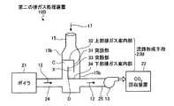
本実施例に係る第二の排ガス処理装置10Bは、規制手段として用いられる流路形成手段23Bが、煙突15の長手方向の断面方向から見たときに、排ガス12が流入する側の煙突15の壁面15b側から延び、その先端部に下向きに突設させた第1の突設部31を有する上部排ガス案内部32と、排ガス12が排出される煙突15の内壁15b側から延び、その先端部に上向きに突設させた第2の突設部33を有する下部排ガス案内部34とからなり、下部排ガス案内部34の第2の突設部33が、煙突15の内壁15bと上部排ガス案内部32の第1の突設部31との間に設けられ、煙突15内に排ガス12の流路を形成してなるものである。 In the second exhaust
ボイラ21から排出され排ガス通路24に送給される排ガス12は、煙突15内を通過して排ガス排出通路25を介してCO2回収装置22側に送給される。ボイラ21、CO2回収装置22など装置の運転が停止等した場合、煙突15内に流入した排ガス12は排ガス排出通路25を介してCO2回収装置22側に送給されるほか、内壁15bと第2の突設部33とにより形成される空間を上昇し、内壁15bと、上部排ガス案内部32と、第1の突設部31とにより形成される空間Cにまで送給される。一方、煙突15の内に流入した大気17は内壁15bと第1の突設部31とにより形成される空間を下降し、内壁15bと、下部排ガス案内部34と、第2の突設部33とにより形成される空間Dにまで送給される。The
排ガス12の温度の方が大気17の温度よりも高いため、空間Cにある排ガス12と空間Dにある大気17とが接触すると、排ガス12と大気17との温度差に起因して生じる排ガス12と大気17との密度差により、排ガス12には浮力が発生し、大気17よりも上方に滞留する。この排ガス12と大気17との温度差と密度差とによる相互作用により排ガス12と大気17との境界領域Xが形成される。そのため、空間Cの排ガス12は、空間Dの大気17によって排ガス12の進行が妨げられるため、排ガス12を空間Cに滞留させることができる。一方、大気17は、空間Cに滞留している排ガス12によって大気17の進行が妨げられるため、大気17を空間Dに滞留させることができる。 Since the temperature of the
よって、煙突15内に流入してきた排ガス12は、排ガス12と大気17との温度差と密度差とによる相互作用により形成される排ガス12と大気17との境界領域Xにおいて大気17によりシールされるため、煙突15の外部に排ガス12が排出されるのを防止することができる。 Therefore, the
また、本実施例に係る第二の排ガス処理装置10Bにおいては、流路形成手段として流路形成手段23Bのみを煙突15内に設けるようにしているが、本発明はこれに限定されるものではなく、図1に示す実施例1に係る第一の排ガス処理装置10Aの流路形成手段23Aを併用するようにしてもよい。 Further, in the second exhaust
図4は、本発明の実施例3に係る排ガス処理装置の概略図である。本実施例に係る排ガス処理装置について、図4を参照して説明する。なお、実施例1に係る排ガス処理装置の構成と重複する部材については、同一符号を付してその説明は省略する。 FIG. 4 is a schematic diagram of an exhaust gas treatment apparatus according to Embodiment 3 of the present invention. An exhaust gas treatment apparatus according to the present embodiment will be described with reference to FIG. In addition, about the member which overlaps with the structure of the waste gas processing apparatus which concerns on Example 1, the same code | symbol is attached | subjected and the description is abbreviate | omitted.
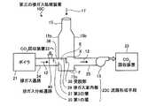
本実施例に係る第三の排ガス処理装置10Cは、規制手段として用いられる流路形成手段23Cは、煙突15の長手方向の断面方向から見たときに、ボイラ21から煙突15に排ガス12を送給する排ガス通路24の上側に設けられる第1の堰35と、排ガス12を煙突15内に送給する煙突15の入口部36の下側に設けられる第2の堰37と、煙突15の入口部36のある内壁15b側から延び、その先端部に下向きに突設させた突設部38を有する排ガス案内部39とからなるものである。 In the third exhaust
ボイラ21から排出される排ガス12は、第1の堰35と、排ガス案内部39と、突設部38とにより形成される空間Eに送給され、排ガス排出通路25を介してCO2回収装置22側に送給される。ボイラ21、CO2回収装置22など装置の運転が停止等した場合、排ガス通路24から送給される排ガス12は、空間Eまで送給される。一方、大気17が煙突15の内部に流入し、煙突15の内部に流入した大気17は内壁15bと突設部38とにより形成される空間を下降し、内壁15bと、第2の堰37と、煙突15の底部15cとにより形成される空間Fにまで送給される。The
排ガス通路24から送給される排ガス12の温度の方が大気17の温度よりも高いため、空間Eにある排ガス12と空間Fにある大気17とが接触すると、排ガス12と大気17との温度差に起因して生じる排ガス12と大気17との密度差により、排ガス12は大気17よりも上方に滞留する。この排ガス12と大気17との温度差と密度差とによる相互作用により排ガス12と大気17との境界領域Xが形成される。 Since the temperature of the
よって、空間Eの排ガス12は、空間Fの大気17によって排ガス12の進行が妨げられるため、排ガス12を空間Eに滞留させることができると共に、大気17は空間Eに滞留している排ガス12によって大気17の進行が妨げられるため、大気17を空間Fに滞留させることができる。このため、煙突15内に送給された排ガス12は、排ガス12と大気17との温度差と密度差とによる相互作用により形成される排ガス12と大気17との境界領域Xにおいて空間Fの大気17によりシールされるため、煙突15の外部に排ガス12が排出されるのを防止することができる。 Therefore, since the
また、排ガス通路24にCO2回収装置22に排ガス12を送給する排ガス分岐通路40を設けるようにしてもよい。産業設備に設けられるボイラ21やガスタービン等の運転が停止した場合に排ガス通路24中に残留している排ガス12や空間Eにある排ガス12を排ガス分岐通路40から抜出してCO2回収装置22に送給することができる。Further, an exhaust
また、本実施例に係る第三の排ガス処理装置10Cにおいては、排ガス通路24の上側に第1の堰35を設けるようにしているが、排ガス12を突設部38と排ガス案内部39とにより形成される空間Eの領域に排ガス12を滞留させて大気17よりも上方に位置するようにし、シールすることができればよいため、第1の堰35を設けないようにしてもよい。 Further, in the third exhaust
また、本実施例に係る第三の排ガス処理装置10Cにおいては、流路形成手段として流路形成手段23Cのみを煙突15内に設けるようにしているが、本発明はこれに限定されるものではなく、図1に示す実施例1に係る第一の排ガス処理装置10Aの流路形成手段23A、図3に示す実施例2に係る第二の排ガス処理装置10Bの流路形成手段23Bの何れか一方又は両方を併用するようにしてもよい。 Further, in the third exhaust
図5は、本発明の実施例4に係る排ガス処理装置の概略図である。本実施例に係る排ガス処理装置について、図5を参照して説明する。なお、実施例1に係る排ガス処理装置の構成と重複する部材については、同一符号を付してその説明は省略する。 FIG. 5 is a schematic view of an exhaust gas treatment apparatus according to Embodiment 4 of the present invention. An exhaust gas treatment apparatus according to the present embodiment will be described with reference to FIG. In addition, about the member which overlaps with the structure of the waste gas processing apparatus which concerns on Example 1, the same code | symbol is attached | subjected and the description is abbreviate | omitted.
本実施例に係る第四の排ガス処理装置10Dは、規制手段として、排ガス12と大気17とを混合するスタティックミキサー(混合手段)41が用いられる。スタティックミキサー41を煙突15内に設けることにより、大気17が煙突15内に流入した際、スタティックミキサー41において排ガス12と大気17とが混合され、排ガス12と大気17との流れをなくすことができるため、煙突15内への大気17の流入を低減することができる。また、煙突15内から排ガス12、大気17のみが排出されるのを防ぐことができる。このため、CO2回収装置22など装置の運転が停止等した場合においても煙突15内への大気17の流入を低減することができ、簡易な構造で煙突15から外部に排出される排ガス12をほぼ全量、安定かつ安全にCO2回収装置22側に引き込むことができると共に、大気17のCO2回収装置22などへの引き込みを抑制することができる。In the fourth exhaust
また、本実施例に係る第四の排ガス処理装置10Dにおいては、図6に示すように、ブロア13からCO2回収装置22に送給される排ガス12の一部を煙突15内に還流させる排ガス還流通路42を設けるようにしてもよい。排ガス還流通路42から排ガス12の一部を煙突15内に戻すことにより、煙突15の外部から大気17が煙突15内に流入し難くすることができるため、大気17の煙突15内への流入を更に低減することができる。Further, in the fourth exhaust
また、本実施例に係る第四の排ガス処理装置10Dにおいては、混合手段としてスタティックミキサー41のような螺旋部材を用いて説明したが、本発明はこれに限定されるものではなく、排ガス12と大気17とを混合することが可能な螺旋部材であれば用いることも可能である。また、螺旋部材以外にも排ガス12と大気17とを混合することが可能な部材であれば用いることができる。 In the fourth exhaust
また、本実施例に係る第四の排ガス処理装置10Dにおいては、混合手段としてスタティックミキサー41のみを煙突15内に設けるようにしているが、本発明はこれに限定されるものではなく、図1に示す実施例1に係る第一の排ガス処理装置10Aの流路形成手段23A、図3に示す実施例2に係る第二の排ガス処理装置10Bの流路形成手段23B、図4に示す実施例3に係る第三の排ガス処理装置10Cの流路形成手段23Cの少なくとも一つを併用するようにしてもよい。 Further, in the fourth exhaust
図7は、本発明の実施例5に係る排ガス処理装置の概略図である。本実施例に係る排ガス処理装置について、図7を参照して説明する。なお、実施例1に係る排ガス処理装置の構成と重複する部材については、同一符号を付してその説明は省略する。 FIG. 7 is a schematic view of an exhaust gas treatment apparatus according to Embodiment 5 of the present invention. An exhaust gas treatment apparatus according to the present embodiment will be described with reference to FIG. In addition, about the member which overlaps with the structure of the waste gas processing apparatus which concerns on Example 1, the same code | symbol is attached | subjected and the description is abbreviate | omitted.
本実施例に係る第五の排ガス処理装置10Eは、規制手段として、大気17が煙突15の内部に流入するのを抑制するリーク抑制手段が用いられる。本実施例では、前記リーク抑制手段として、煙突15の内壁15bに煙突15の長手方向の断面方向から見たときに煙突15の出口方向に向かって延びる抵抗部51が3つ設けられている。この抵抗部51は煙突15の内壁15bに沿って設けられている。 In the fifth exhaust
大気17は排ガス12に比べて温度が低いため、煙突15内に流入した大気17は煙突15の内壁側に沿って降下する流量が煙突15内の中心部分を降下する流量よりも多い。そのため、煙突15内の内壁15bに抵抗部51を設けることで、煙突15の内壁側に沿って降下する大気17の流入量を抑制することができる。また、煙突15内の中心部分より降下してくる大気17は、煙突15内に送給され、上昇してくる排ガス12により煙突15内への流入を低減することができる。このため、CO2回収装置22など装置の運転が停止等した場合においても煙突15内への大気17の流入量を低減することができ、簡易な構造で煙突15から外部に排出される排ガス12をほぼ全量、安定かつ安全にCO2回収装置22側に引き込むことができると共に、大気17のCO2回収装置22などへの引き込みを抑制することができる。Since the
また、本実施例に係る第五の排ガス処理装置10Eにおいては、抵抗部51を3つ設けるようにしているが、大気17の抑制割合などに応じて抵抗部51の設置数を適宜変更するようにすればよい。 Further, in the fifth exhaust
また、本実施例に係る第五の排ガス処理装置10Eにおいては、抵抗部として煙突15の長手方向の断面方向から見たときに煙突15出口方向に向かって延びる構造のものを採用しているが、本発明はこれに限定されるものではなく、煙突15内に大気17が流入するのを抑制することが可能な部材であればよい。 Further, in the fifth exhaust
また、本実施例に係る第五の排ガス処理装置10Eにおいては、規制手段として大気17が煙突15の内部に流入するのを抑制するリーク抑制手段のみを煙突15内に設けるようにしているが、本発明はこれに限定されるものではない。例えば、図1に示す実施例1に係る第一の排ガス処理装置10Aの流路形成手段23A、図3に示す実施例2に係る第二の排ガス処理装置10Bの流路形成手段23B、図4に示す実施例3に係る第三の排ガス処理装置10Cの流路形成手段23C、図5に示す実施例4に係る第四の排ガス処理装置10Dの混合手段41の少なくとも一つを併用するようにしてもよい。 Further, in the fifth exhaust
図8は、本発明の実施例6に係る排ガス処理装置の概略図である。本実施例に係る排ガス処理装置について、図8を参照して説明する。なお、実施例1に係る排ガス処理装置の構成と重複する部材については、同一符号を付してその説明は省略する。 FIG. 8 is a schematic view of an exhaust gas treatment apparatus according to Embodiment 6 of the present invention. An exhaust gas treatment apparatus according to the present embodiment will be described with reference to FIG. In addition, about the member which overlaps with the structure of the waste gas processing apparatus which concerns on Example 1, the same code | symbol is attached | subjected and the description is abbreviate | omitted.
本実施例に係る第六の排ガス処理装置10Fは、規制手段として、排ガス12が煙突15内に送給される煙突15の入口部36に煙突15の内側の一方向にのみ開閉可能なダンパ(開閉手段)52が用いられる。 The sixth exhaust
ダンパ52は入口部36の一端側を軸として煙突15の内側に開閉可能な構造である。このため、内壁15bの入口部36にダンパ52を設けることで、CO2回収装置22が稼動しブロア13で排ガス12を引いている場合、ボイラ21やガスタービン等の産業設備が稼動し排ガス通路24内が正圧の状態などの場合には、ダンパ52は煙突15の内側の一方向にのみ開閉可能であるため、ダンパ52を煙突15の内側に常に開放された状態とすることができ、排ガス12をCO2回収装置22側に引き込むことができる。The damper 52 has a structure that can be opened and closed inside the
また、煙突15の前流側に位置するボイラ21やガスタービン等の産業設備、CO2回収装置22などの装置の運転が停止等した場合には、ダンパ52により入口部36を閉鎖することができるため、大気17がボイラ21やガスタービン等の産業設備へ流入するのを防止することができる。In addition, when the operation of an equipment such as a
また、排ガス通路24にCO2回収装置22に排ガス12を送給する排ガス分岐通路40を設けるようにしてもよい。ボイラ21やガスタービン等の産業設備の運転が停止し、CO2回収装置22が稼動している場合に排ガス通路24中に残留している排ガス12を排ガス分岐通路40から抜出してCO2回収装置22に送給するようにしてもよい。また、ボイラ21やガスタービン等の産業設備が稼動し、CO2回収装置22などの装置が運転していない場合などでは、排ガス通路24内にある排ガス12を排ガス分岐通路40から抜出してCO2回収装置22が可動した際にCO2回収装置22内に送給するようにしてもよい。ボイラ21やガスタービン等の産業設備、CO2回収装置22の運転が停止している場合にもCO2回収装置22が可動した際に排ガス通路24中に残留している排ガス12を排ガス分岐通路40から抜出してCO2回収装置22に送給するようにしてもよい。Further, an exhaust
また、本実施例に係る第六の排ガス処理装置10Fにおいては、開閉手段として煙突15の入口部36に煙突15の内側の一方向にのみ開閉可能なダンパ52のみを設けるようにしているが、本発明はこれに限定されるものではない。例えば、図1に示す実施例1に係る第一の排ガス処理装置10Aの流路形成手段23A、図3に示す実施例2に係る第二の排ガス処理装置10Bの流路形成手段23B、図4に示す実施例3に係る第三の排ガス処理装置10Cの流路形成手段23C、図5に示す実施例4に係る第四の排ガス処理装置10Dの混合手段41、図7に示す実施例5に係る第五の排ガス処理装置10Eの抵抗部51の少なくとも一つを併用するようにしてもよい。 Further, in the sixth exhaust
また、本発明は、CO2回収装置22を備える排ガス処理装置に用いる場合について説明したが、CO2回収装置22以外に排煙脱硫装置など他の装置を備える排ガス処理装置にも用いることは可能である。Further, the present invention has been described for use in the exhaust gas treatment apparatus comprising a CO2 recovering apparatus 22, also be used in exhaust gas treatment apparatus provided with other devices such as a flue gas desulfurization apparatus other than the CO2 recovering apparatus 22 is capable It is.
以上のように、本発明に係る排ガス処理装置は、煙突から外部に排出される排ガスをほぼ全量、安定かつ安全にCO2回収装置側に引き込むと共に、煙突内への大気の引き込みを抑制することに用いるのに適している。As described above, the exhaust gas treatment apparatus according to the present invention draws almost all of the exhaust gas discharged from the chimney to the CO2 recovery device side in a stable and safe manner and suppresses the air from being drawn into the chimney. Suitable for use in.
10A〜10F 第一の排ガス処理装置〜第六の排ガス処理装置
11 ボイラ
12 排ガス
13 ブロア
14 排煙脱硫装置
15 煙突
16 ダンパ
17 大気
21 ボイラ
22 CO2回収装置
23A〜23C 流路形成手段
24 排ガス通路
25 排ガス排出通路
26 開口
27 突設部
28 仕切部
29 蓋部
31 第1の突設部
32 上部排ガス案内部
33 第2の突設部
34 下部排ガス案内部
35 第1の堰
36 入口部
37 第2の堰
38 突設部
39 排ガス案内部
40 排ガス分岐通路
41 スタティックミキサー(螺旋部材)
42 排ガス還流通路
51 抵抗部
52 ダンパ
A〜F 空間
X 境界領域10A to 10F First exhaust gas treatment device to sixth exhaust
42 Exhaust gas recirculation passage 51 Resistance portion 52 Damper A to F Space X Boundary region
Claims (9)
Translated fromJapanese前記煙突の後流側に設置され、前記煙突内の前記排ガスを引込むブロアと、
前記ブロアにより引込まれた排ガス中のCO2を回収するCO2回収装置と、
前記煙突内に設けられ、前記CO2回収装置が運転及び運転を停止している際に、前記ブロアにより引込まれた前記排ガスが前記煙突内から外部に放出されるのを抑制すると共に、大気が前記煙突の内部に流入するのを抑制する規制手段と、を具備し、
前記規制手段が、前記煙突内に前記ブロアにより引込まれた前記排ガス及び前記大気が流れる蛇行流路を形成する流路形成手段であることを特徴とする排ガス処理装置。A chimney capable of discharging exhaust gas discharged from industrial facilities to the outside,
A blower that is installed on the downstream side of the chimney and draws the exhaust gas in the chimney;
A CO2 recovery device that recovers CO2 in the exhaust gas drawn by the blower;
The exhaust gas drawn in by the blower is suppressed from being released to the outside from the inside of the chimney when the CO2 recovery device provided in the chimney is stopped and operated, and the atmosphere Restricting means for suppressing the flow into the chimney, and
The exhaust gas treatment apparatus, wherein the restriction means is a flow path forming means for forming a meandering flow path through which the exhaust gas drawn into the chimney by the blower and the atmosphere flow.
前記流路形成手段が、前記煙突の長手方向の断面方向の中心部分に開口を形成し、前記煙突の塔頂部側に突設した突設部を有する仕切部と、該仕切部と所定の隙間を設けて対向するように設けられる凹状の蓋部とからなることを特徴とする排ガス処理装置。In claim 1,
The flow path forming means has an opening at a central portion in a cross-sectional direction in the longitudinal direction of the chimney, and has a partition portion having a projecting portion projecting on the tower top side of the chimney, and a predetermined gap from the partition portion An exhaust gas treatment apparatus comprising a concave lid portion provided so as to face each other.
前記流路形成手段が、前記煙突の長手方向の断面方向から見たときに、前記排ガスが流入する側の前記煙突の壁面側から延び、その先端部に下向きに突設させた第1の突設部を有する上部排ガス案内部と、前記排ガスが排出される前記煙突の壁面側から延び、その先端部に上向きに突設させた第2の突設部を有する下部排ガス案内部とからなり、
前記下部排ガス案内部の前記第2の突設部が、前記煙突の壁面と前記上部排ガス案内部の前記第1の突設部との間に設けられ、前記煙突内に排ガスの流路を形成してなることを特徴とする排ガス処理装置。In claim 1,
When the flow path forming means is viewed from the longitudinal cross-sectional direction of the chimney, the first projection extends from the wall surface side of the chimney on the side into which the exhaust gas flows and projects downward at the tip thereof. An upper exhaust gas guide portion having an installation portion, and a lower exhaust gas guide portion having a second projection portion extending from the wall surface side of the chimney from which the exhaust gas is discharged and projecting upward at the tip portion thereof,
The second projecting portion of the lower exhaust gas guide portion is provided between a wall surface of the chimney and the first projecting portion of the upper exhaust gas guide portion, and forms an exhaust gas flow path in the chimney. An exhaust gas treatment apparatus characterized by comprising:
前記流路形成手段が、前記煙突の長手方向の断面方向から見たときに、前記産業設備から前記煙突に前記排ガスを送給する排ガス通路の上側に設けられる第1の堰と、前記排ガスを前記煙突内に送給する前記煙突の入口部の下側に設けられる第2の堰と、前記煙突の前記入口部のある壁面側から延び、その先端部に下向きに突設させた突設部を有する排ガス案内部とからなるものであることを特徴とする排ガス処理装置。In claim 1,
A first weir provided on an upper side of an exhaust gas passage for supplying the exhaust gas from the industrial equipment to the chimney when the flow path forming unit is viewed from a longitudinal cross-sectional direction of the chimney; A second weir provided on the lower side of the inlet portion of the chimney to be fed into the chimney, and a projecting portion extending downward from a wall surface side of the chimney where the inlet portion is located and projecting downward at the tip thereof An exhaust gas treatment device comprising an exhaust gas guide unit having
前記煙突の後流側に設置され、前記煙突内の前記排ガスを引込むブロアと、
前記ブロアにより引込まれた排ガス中のCO2を回収するCO2回収装置と、
前記煙突内に設けられ、前記CO2回収装置が運転及び運転を停止している際に、前記ブロアにより引込まれた前記排ガスが前記煙突内から外部に放出されるのを抑制すると共に、大気が前記煙突の内部に流入するのを抑制する規制手段と、を具備し、
前記規制手段が、前記煙突内に前記ブロアにより引込まれた前記排ガスと前記大気とを混合する混合手段であることを特徴とする排ガス処理装置。A chimney that exhausts the exhaust gas discharged from industrial facilities to the outside,
A blower that is installed on the downstream side of the chimney and draws the exhaust gas in the chimney;
A CO2 recovery device that recovers CO2 in the exhaust gas drawn by the blower;
The exhaust gas drawn in by the blower is suppressed from being released to the outside from the inside of the chimney when the CO2 recovery device provided in the chimney is stopped and operated, and the atmosphere Restricting means for suppressing the flow into the chimney, and
The exhaust gas treatment apparatus, wherein the regulating means is a mixing means for mixing the exhaust gas drawn into the chimney by the blower and the atmosphere.
前記ブロアから前記CO2回収装置に送給される前記排ガスの一部を前記煙突内に還流させる排ガス還流通路を有することを特徴とする排ガス処理装置。In claim 5,
An exhaust gas treatment device comprising an exhaust gas recirculation passage for recirculating a part of the exhaust gas fed from the blower to the CO2 recovery device into the chimney.
前記煙突の後流側に設置され、前記煙突内の前記排ガスを引込むブロアと、
前記ブロアにより引込まれた排ガス中のCO2を回収し、CO2を回収した前記排ガスを外部に排出可能なCO2回収装置と、
前記煙突内に設けられ、前記CO2回収装置が運転及び運転を停止している際に、前記ブロアにより引込まれた前記排ガスが前記煙突内から外部に放出されるのを抑制すると共に、大気が前記煙突の内部に流入するのを抑制する規制手段と、を具備し、
前記規制手段が、前記大気が前記煙突の内部に流入するのを抑制するリーク抑制手段であることを特徴とする排ガス処理装置。A chimney that exhausts the exhaust gas discharged from industrial facilities to the outside,
A blower that is installed on the downstream side of the chimney and draws the exhaust gas in the chimney;
A CO2 recovery device capable of recovering CO2 in the exhaust gas drawn by the blower and discharging the exhaust gas recovered from the CO2 to the outside;
The exhaust gas drawn in by the blower is suppressed from being released to the outside from the inside of the chimney when the CO2 recovery device provided in the chimney is stopped and operated, and the atmosphere Restricting means for suppressing the flow into the chimney, and
The exhaust gas treatment apparatus according to claim 1, wherein the restriction means is a leak suppression means for suppressing the atmosphere from flowing into the chimney.
前記リーク抑制手段が、前記煙突の壁面に少なくとも一つ設けられ、前記煙突の長手方向の断面方向から見たときに煙突出口方向に向かって延びる抵抗部であることを特徴とする排ガス処理装置。In claim 7,
The exhaust gas treatment apparatus according to claim 1, wherein at least one of the leak suppression means is provided on a wall surface of the chimney, and is a resistance portion that extends in a smoke outlet direction when viewed from a cross-sectional direction in a longitudinal direction of the chimney.
Priority Applications (12)
| Application Number | Priority Date | Filing Date | Title |
|---|---|---|---|
| JP2009055291AJP5751743B2 (en) | 2009-03-09 | 2009-03-09 | Exhaust gas treatment apparatus and exhaust gas treatment method |
| US12/581,649US8202354B2 (en) | 2009-03-09 | 2009-10-19 | Air pollution control apparatus and air pollution control method |
| CA 2683380CA2683380C (en) | 2009-03-09 | 2009-10-21 | Air pollution control apparatus and air pollution control method |
| CA 2791789CA2791789C (en) | 2009-03-09 | 2009-10-21 | Air pollution control apparatus and air pollution control method |
| AU2009230740AAU2009230740B8 (en) | 2009-03-09 | 2009-10-23 | Air pollution control apparatus and air pollution control method |
| EP09174653.7AEP2229999B8 (en) | 2009-03-09 | 2009-10-30 | Air pollution control apparatus and air pollution control method |
| EP19158899.5AEP3530341B1 (en) | 2009-03-09 | 2009-10-30 | Air pollution control apparatus and air pollution control method |
| DK19158899.5TDK3530341T3 (en) | 2009-03-09 | 2009-10-30 | Air pollution control device and method for air pollution management |
| EP21150750.4AEP3827894A1 (en) | 2009-03-09 | 2009-10-30 | Air pollution control apparatus and air pollution control method |
| US13/474,450US8382882B2 (en) | 2009-03-09 | 2012-05-17 | Air pollution control apparatus and air pollution control method |
| US13/474,460US8425669B2 (en) | 2009-03-09 | 2012-05-17 | Air pollution control apparatus and air pollution control method |
| US13/474,440US8361194B2 (en) | 2009-03-09 | 2012-05-17 | Air pollution control apparatus and air pollution control method |
Applications Claiming Priority (1)
| Application Number | Priority Date | Filing Date | Title |
|---|---|---|---|
| JP2009055291AJP5751743B2 (en) | 2009-03-09 | 2009-03-09 | Exhaust gas treatment apparatus and exhaust gas treatment method |
Publications (2)
| Publication Number | Publication Date |
|---|---|
| JP2010207686A JP2010207686A (en) | 2010-09-24 |
| JP5751743B2true JP5751743B2 (en) | 2015-07-22 |
Family
ID=42101413
Family Applications (1)
| Application Number | Title | Priority Date | Filing Date |
|---|---|---|---|
| JP2009055291AActiveJP5751743B2 (en) | 2009-03-09 | 2009-03-09 | Exhaust gas treatment apparatus and exhaust gas treatment method |
Country Status (6)
| Country | Link |
|---|---|
| US (4) | US8202354B2 (en) |
| EP (3) | EP3530341B1 (en) |
| JP (1) | JP5751743B2 (en) |
| AU (1) | AU2009230740B8 (en) |
| CA (2) | CA2683380C (en) |
| DK (1) | DK3530341T3 (en) |
Families Citing this family (41)
| Publication number | Priority date | Publication date | Assignee | Title |
|---|---|---|---|---|
| FR2956592A1 (en)* | 2010-02-23 | 2011-08-26 | Air Liquide | METHOD OF TREATING SMOKE FROM COMBUSTION |
| US9038579B2 (en)* | 2011-05-11 | 2015-05-26 | Korea Institute Of Machinery & Materials | Fuel cell-engine hybrid system |
| US8961664B2 (en)* | 2012-09-20 | 2015-02-24 | Mitsubishi Heavy Industries, Ltd. | Carbon dioxide recovery device |
| CN104707441A (en)* | 2015-03-25 | 2015-06-17 | 尹怀鹏 | Carbon dioxide and methane specific-gravity separator for biogas |
| US11624326B2 (en) | 2017-05-21 | 2023-04-11 | Bj Energy Solutions, Llc | Methods and systems for supplying fuel to gas turbine engines |
| WO2020004629A1 (en)* | 2018-06-28 | 2020-01-02 | 有限会社手島通商 | Device for recovering polluted air |
| US11560845B2 (en) | 2019-05-15 | 2023-01-24 | Bj Energy Solutions, Llc | Mobile gas turbine inlet air conditioning system and associated methods |
| US11604113B2 (en) | 2019-09-13 | 2023-03-14 | Bj Energy Solutions, Llc | Fuel, communications, and power connection systems and related methods |
| US11015594B2 (en) | 2019-09-13 | 2021-05-25 | Bj Energy Solutions, Llc | Systems and method for use of single mass flywheel alongside torsional vibration damper assembly for single acting reciprocating pump |
| CA3197583A1 (en) | 2019-09-13 | 2021-03-13 | Bj Energy Solutions, Llc | Fuel, communications, and power connection systems and related methods |
| US10961914B1 (en) | 2019-09-13 | 2021-03-30 | BJ Energy Solutions, LLC Houston | Turbine engine exhaust duct system and methods for noise dampening and attenuation |
| CA3092863C (en) | 2019-09-13 | 2023-07-18 | Bj Energy Solutions, Llc | Fuel, communications, and power connection systems and related methods |
| US12065968B2 (en) | 2019-09-13 | 2024-08-20 | BJ Energy Solutions, Inc. | Systems and methods for hydraulic fracturing |
| CA3092829C (en) | 2019-09-13 | 2023-08-15 | Bj Energy Solutions, Llc | Methods and systems for supplying fuel to gas turbine engines |
| US11002189B2 (en) | 2019-09-13 | 2021-05-11 | Bj Energy Solutions, Llc | Mobile gas turbine inlet air conditioning system and associated methods |
| US10895202B1 (en) | 2019-09-13 | 2021-01-19 | Bj Energy Solutions, Llc | Direct drive unit removal system and associated methods |
| US10815764B1 (en) | 2019-09-13 | 2020-10-27 | Bj Energy Solutions, Llc | Methods and systems for operating a fleet of pumps |
| US12338772B2 (en) | 2019-09-13 | 2025-06-24 | Bj Energy Solutions, Llc | Systems, assemblies, and methods to enhance intake air flow to a gas turbine engine of a hydraulic fracturing unit |
| CA3092865C (en) | 2019-09-13 | 2023-07-04 | Bj Energy Solutions, Llc | Power sources and transmission networks for auxiliary equipment onboard hydraulic fracturing units and associated methods |
| US11708829B2 (en) | 2020-05-12 | 2023-07-25 | Bj Energy Solutions, Llc | Cover for fluid systems and related methods |
| US10968837B1 (en) | 2020-05-14 | 2021-04-06 | Bj Energy Solutions, Llc | Systems and methods utilizing turbine compressor discharge for hydrostatic manifold purge |
| US11428165B2 (en) | 2020-05-15 | 2022-08-30 | Bj Energy Solutions, Llc | Onboard heater of auxiliary systems using exhaust gases and associated methods |
| US11208880B2 (en) | 2020-05-28 | 2021-12-28 | Bj Energy Solutions, Llc | Bi-fuel reciprocating engine to power direct drive turbine fracturing pumps onboard auxiliary systems and related methods |
| US11208953B1 (en) | 2020-06-05 | 2021-12-28 | Bj Energy Solutions, Llc | Systems and methods to enhance intake air flow to a gas turbine engine of a hydraulic fracturing unit |
| US11109508B1 (en) | 2020-06-05 | 2021-08-31 | Bj Energy Solutions, Llc | Enclosure assembly for enhanced cooling of direct drive unit and related methods |
| US11066915B1 (en) | 2020-06-09 | 2021-07-20 | Bj Energy Solutions, Llc | Methods for detection and mitigation of well screen out |
| US10954770B1 (en) | 2020-06-09 | 2021-03-23 | Bj Energy Solutions, Llc | Systems and methods for exchanging fracturing components of a hydraulic fracturing unit |
| US11111768B1 (en) | 2020-06-09 | 2021-09-07 | Bj Energy Solutions, Llc | Drive equipment and methods for mobile fracturing transportation platforms |
| US11933153B2 (en) | 2020-06-22 | 2024-03-19 | Bj Energy Solutions, Llc | Systems and methods to operate hydraulic fracturing units using automatic flow rate and/or pressure control |
| US11939853B2 (en) | 2020-06-22 | 2024-03-26 | Bj Energy Solutions, Llc | Systems and methods providing a configurable staged rate increase function to operate hydraulic fracturing units |
| US11028677B1 (en) | 2020-06-22 | 2021-06-08 | Bj Energy Solutions, Llc | Stage profiles for operations of hydraulic systems and associated methods |
| US11125066B1 (en) | 2020-06-22 | 2021-09-21 | Bj Energy Solutions, Llc | Systems and methods to operate a dual-shaft gas turbine engine for hydraulic fracturing |
| US11473413B2 (en) | 2020-06-23 | 2022-10-18 | Bj Energy Solutions, Llc | Systems and methods to autonomously operate hydraulic fracturing units |
| US11466680B2 (en) | 2020-06-23 | 2022-10-11 | Bj Energy Solutions, Llc | Systems and methods of utilization of a hydraulic fracturing unit profile to operate hydraulic fracturing units |
| US11149533B1 (en) | 2020-06-24 | 2021-10-19 | Bj Energy Solutions, Llc | Systems to monitor, detect, and/or intervene relative to cavitation and pulsation events during a hydraulic fracturing operation |
| US11220895B1 (en) | 2020-06-24 | 2022-01-11 | Bj Energy Solutions, Llc | Automated diagnostics of electronic instrumentation in a system for fracturing a well and associated methods |
| US11193360B1 (en) | 2020-07-17 | 2021-12-07 | Bj Energy Solutions, Llc | Methods, systems, and devices to enhance fracturing fluid delivery to subsurface formations during high-pressure fracturing operations |
| US11639654B2 (en) | 2021-05-24 | 2023-05-02 | Bj Energy Solutions, Llc | Hydraulic fracturing pumps to enhance flow of fracturing fluid into wellheads and related methods |
| CA3180024A1 (en) | 2021-10-25 | 2023-04-25 | Bj Energy Solutions, Llc | Systems and methods to reduce acoustic resonance or disrupt standing wave formation in a fluid manifold of a high-pressure fracturing system |
| NO347320B1 (en)* | 2021-11-23 | 2023-09-18 | Aker Carbon Capture Norway As | Plant and Method of Controlling an Industrial Plant having a Flue Gas Processing System |
| JP2024116657A (en)* | 2023-02-16 | 2024-08-28 | 三菱重工業株式会社 | Control device, exhaust gas supply system, control method and program |
Family Cites Families (48)
| Publication number | Priority date | Publication date | Assignee | Title |
|---|---|---|---|---|
| US1044501A (en)* | 1911-03-08 | 1912-11-19 | William Crawford | Spark-arrester. |
| DE293773C (en)* | 1913-01-30 | |||
| CH77930A (en)* | 1917-12-08 | 1918-11-01 | Spoerri & Co | Apparatus for suppressing smoke, dust and vapors |
| US2608461A (en)* | 1949-03-26 | 1952-08-26 | Fluor Corp | Prevention of amine losses in gas treating systems |
| US2826264A (en)* | 1956-06-25 | 1958-03-11 | Simpson Herbert Corp | Flue gas purification system |
| US3368578A (en)* | 1965-10-22 | 1968-02-13 | Foster Wheeler Corp | Integral seal pot arrangement |
| DE1544080B2 (en)* | 1965-11-15 | 1974-12-12 | Metallgesellschaft Ag, 6000 Frankfurt | Process for cleaning highly compressed gases containing carbon dioxide |
| GB1104013A (en) | 1966-08-03 | 1968-02-21 | Alcorn Comb Co | Improvements in systems for firing off-gas from the catalyst regenerator of a hydrocarbon catalytic cracking unit |
| US3638636A (en)* | 1970-01-22 | 1972-02-01 | Lear Siegler Inc | Air heater |
| US3690636A (en) | 1970-12-03 | 1972-09-12 | United States Steel Corp | Recuperative furnaces |
| US3729901A (en)* | 1971-07-20 | 1973-05-01 | D Jackson | Emission and pollutant recovery process and apparatus |
| US4084944A (en)* | 1976-09-20 | 1978-04-18 | Ecodyne Corporation | Pure distillate recovery system |
| US4168958A (en)* | 1977-03-23 | 1979-09-25 | Hartman Eugene W | Smoke stack air washer |
| US4113005A (en)* | 1977-04-22 | 1978-09-12 | John Zink Company | Waste heat boiler temperature control system |
| JPS5654430Y2 (en)* | 1979-05-01 | 1981-12-18 | ||
| JPS5658129U (en)* | 1979-10-09 | 1981-05-19 | ||
| DE3409214A1 (en)* | 1983-03-18 | 1984-10-04 | Joh. Vaillant Gmbh U. Co, 5630 Remscheid | Waste-gas removal device for a fuel-heated heat source |
| DE3346865C1 (en) | 1983-12-23 | 1985-04-18 | Air Fröhlich AG für Energierückgewinnung, Arbon | Method and device for separating pollutants from a flue gas |
| JPS6354515A (en)* | 1986-08-22 | 1988-03-08 | Fuji Kako Kk | Stack drain preventive device |
| US5076818A (en)* | 1990-06-28 | 1991-12-31 | Jonsson Kjartan A | Gas cleaning methods and apparatus |
| US5035188A (en) | 1990-09-11 | 1991-07-30 | It-Mcgill Pollution Control Systems, Inc. | Liquid blowdown elimination system |
| DE69206846T3 (en)* | 1991-03-07 | 1999-11-25 | Mitsubishi Jukogyo K.K., Tokio/Tokyo | Device and method for removing carbon dioxide from exhaust gases |
| US5171557A (en)* | 1991-05-28 | 1992-12-15 | Ford Motor Company | Method for silicon nitride precursor solids recovery |
| EP0553643B1 (en)* | 1992-01-17 | 1998-05-13 | The Kansai Electric Power Co., Inc. | Method for treating combustion exhaust gas |
| JPH0791630A (en)* | 1993-09-21 | 1995-04-04 | Kyodo Kumiai Jiyou Tekutsu | Method and apparatus for incineration |
| JPH0791277A (en)* | 1993-09-24 | 1995-04-04 | Mitsubishi Heavy Ind Ltd | Exhaust dust |
| JPH07305829A (en) | 1994-05-11 | 1995-11-21 | Mitsubishi Heavy Ind Ltd | Dust collector |
| JP2974932B2 (en)* | 1995-05-25 | 1999-11-10 | 徳光 松元 | Incinerator |
| JP2721657B2 (en)* | 1996-02-19 | 1998-03-04 | 有限会社朝日鉄筋 | Incinerator |
| DE69921853T2 (en) | 1998-12-01 | 2005-12-08 | Ebara Corp. | DEVICE FOR TREATMENT OF EXHAUST GAS |
| US6399030B1 (en)* | 1999-06-04 | 2002-06-04 | The Babcock & Wilcox Company | Combined flue gas desulfurization and carbon dioxide removal system |
| US6383462B1 (en) | 1999-10-26 | 2002-05-07 | John Zink Company, Llc | Fuel dilution methods and apparatus for NOx reduction |
| JP2001292641A (en)* | 2000-04-13 | 2001-10-23 | Yamamoto Co Ltd | Apparatus for feeding carbon dioxide gas in greenhouse or plastic greenhouse |
| JP3969949B2 (en)* | 2000-10-25 | 2007-09-05 | 関西電力株式会社 | Amine recovery method and apparatus, and decarbonation gas apparatus provided with the same |
| JP2002180066A (en)* | 2000-12-15 | 2002-06-26 | Nippon Steel Corp | Coal humidity control equipment using coke oven exhaust gas |
| JP2003074815A (en)* | 2001-08-28 | 2003-03-12 | Shikoku Kakoki Co Ltd | Wet food processor |
| US7118721B2 (en) | 2002-11-26 | 2006-10-10 | Alstom Technology Ltd | Method for treating emissions |
| JP2005214458A (en)* | 2004-01-27 | 2005-08-11 | Honda Motor Co Ltd | Air humidification method |
| JP4745682B2 (en) | 2005-02-23 | 2011-08-10 | 関西電力株式会社 | CO2 recovery apparatus and method |
| US7442035B2 (en)* | 2005-04-26 | 2008-10-28 | Gei Development, Llc | Gas induction bustle for use with a flare or exhaust stack |
| GB2434330B (en)* | 2006-01-13 | 2010-02-17 | Project Invest Energy As | Removal of CO2 from flue gas |
| JP2007285660A (en)* | 2006-04-20 | 2007-11-01 | Ikeda Akira | Wood stove |
| JP5230088B2 (en) | 2006-09-06 | 2013-07-10 | 三菱重工業株式会社 | CO2 recovery apparatus and method |
| JP4693741B2 (en)* | 2006-10-06 | 2011-06-01 | 中国電力株式会社 | Bypass flue air volume adjustment device, flue gas desulfurization device |
| JP2008307520A (en) | 2007-06-18 | 2008-12-25 | Mitsubishi Heavy Ind Ltd | Co2 or h2s removal system, co2 or h2s removal method |
| US8728423B2 (en)* | 2008-04-07 | 2014-05-20 | Mitsubishi Heavy Industries, Ltd. | Method and apparatus for flue gas treatment |
| AU2008357629B2 (en)* | 2008-06-13 | 2015-09-03 | Sigan Peng | Washing device and washing method for marine exhaust flue gases |
| US8647421B2 (en) | 2011-03-17 | 2014-02-11 | Mitsubishi Heavy Industries, Ltd. | CO2 recovery apparatus |
- 2009
- 2009-03-09JPJP2009055291Apatent/JP5751743B2/enactiveActive
- 2009-10-19USUS12/581,649patent/US8202354B2/enactiveActive
- 2009-10-21CACA 2683380patent/CA2683380C/enactiveActive
- 2009-10-21CACA 2791789patent/CA2791789C/enactiveActive
- 2009-10-23AUAU2009230740Apatent/AU2009230740B8/enactiveActive
- 2009-10-30DKDK19158899.5Tpatent/DK3530341T3/enactive
- 2009-10-30EPEP19158899.5Apatent/EP3530341B1/enactiveActive
- 2009-10-30EPEP21150750.4Apatent/EP3827894A1/enactivePending
- 2009-10-30EPEP09174653.7Apatent/EP2229999B8/enactiveActive
- 2012
- 2012-05-17USUS13/474,460patent/US8425669B2/enactiveActive
- 2012-05-17USUS13/474,440patent/US8361194B2/enactiveActive
- 2012-05-17USUS13/474,450patent/US8382882B2/enactiveActive
Also Published As
| Publication number | Publication date |
|---|---|
| US8202354B2 (en) | 2012-06-19 |
| EP2229999A2 (en) | 2010-09-22 |
| US20100224064A1 (en) | 2010-09-09 |
| US20120255441A1 (en) | 2012-10-11 |
| EP3530341A2 (en) | 2019-08-28 |
| DK3530341T3 (en) | 2021-03-01 |
| CA2683380C (en) | 2013-01-08 |
| EP2229999B1 (en) | 2019-04-10 |
| JP2010207686A (en) | 2010-09-24 |
| AU2009230740A8 (en) | 2015-03-12 |
| EP3530341A3 (en) | 2019-12-18 |
| US20120255442A1 (en) | 2012-10-11 |
| CA2791789A1 (en) | 2010-09-09 |
| US8425669B2 (en) | 2013-04-23 |
| US20120222394A1 (en) | 2012-09-06 |
| EP2229999B8 (en) | 2019-10-16 |
| AU2009230740B8 (en) | 2015-03-12 |
| US8382882B2 (en) | 2013-02-26 |
| EP3530341B1 (en) | 2021-02-17 |
| EP2229999A3 (en) | 2011-05-18 |
| CA2791789C (en) | 2014-11-25 |
| CA2683380A1 (en) | 2010-09-09 |
| AU2009230740B2 (en) | 2014-10-23 |
| AU2009230740A1 (en) | 2010-09-23 |
| US8361194B2 (en) | 2013-01-29 |
| EP3827894A1 (en) | 2021-06-02 |
Similar Documents
| Publication | Publication Date | Title |
|---|---|---|
| JP5751743B2 (en) | Exhaust gas treatment apparatus and exhaust gas treatment method | |
| JP2009240908A (en) | Wet two step flue gas desulfurization apparatus and operation method of wet two step flue gas desulfurization apparatus | |
| JP5717382B2 (en) | Smoke exhaust treatment device and smoke exhaust treatment method | |
| JPWO2011058906A1 (en) | Mercury removal apparatus and mercury removal method | |
| JP2022058368A (en) | Exhaust gas treatment system | |
| KR102059188B1 (en) | Wet flue gas desulfurization apparatus and wet flue gas desulfurization method | |
| JP2011125765A (en) | Flue gas denitration apparatus | |
| KR20250009429A (en) | Waste incineration facility | |
| JP2011127597A (en) | System and method for reducing sulfur compounds within fuel stream for turbomachine | |
| AU2014240212B2 (en) | Air pollution control apparatus and air pollution control method | |
| JP2009121480A (en) | Auxiliary fluid source for egr purge system | |
| JP5019361B2 (en) | How to cope with increase of absorbent slurry concentration in flue gas desulfurization equipment | |
| KR101552863B1 (en) | Method for reducing chrome yellow of nitrogen oxide elimination system | |
| JP5968028B2 (en) | Boiler combustion equipment | |
| KR20140025643A (en) | Soot removing apparatus | |
| JP2008132424A (en) | Exhaust gas treatment apparatus and operation method of waste treatment facility equipped with the same |
Legal Events
| Date | Code | Title | Description |
|---|---|---|---|
| A621 | Written request for application examination | Free format text:JAPANESE INTERMEDIATE CODE: A621 Effective date:20120222 | |
| A977 | Report on retrieval | Free format text:JAPANESE INTERMEDIATE CODE: A971007 Effective date:20120727 | |
| A131 | Notification of reasons for refusal | Free format text:JAPANESE INTERMEDIATE CODE: A131 Effective date:20130618 | |
| A521 | Request for written amendment filed | Free format text:JAPANESE INTERMEDIATE CODE: A523 Effective date:20130808 | |
| A131 | Notification of reasons for refusal | Free format text:JAPANESE INTERMEDIATE CODE: A131 Effective date:20140603 | |
| A521 | Request for written amendment filed | Free format text:JAPANESE INTERMEDIATE CODE: A523 Effective date:20140730 | |
| A131 | Notification of reasons for refusal | Free format text:JAPANESE INTERMEDIATE CODE: A131 Effective date:20150127 | |
| A521 | Request for written amendment filed | Free format text:JAPANESE INTERMEDIATE CODE: A523 Effective date:20150327 | |
| TRDD | Decision of grant or rejection written | ||
| A01 | Written decision to grant a patent or to grant a registration (utility model) | Free format text:JAPANESE INTERMEDIATE CODE: A01 Effective date:20150421 | |
| A61 | First payment of annual fees (during grant procedure) | Free format text:JAPANESE INTERMEDIATE CODE: A61 Effective date:20150519 | |
| R151 | Written notification of patent or utility model registration | Ref document number:5751743 Country of ref document:JP Free format text:JAPANESE INTERMEDIATE CODE: R151 | |
| S111 | Request for change of ownership or part of ownership | Free format text:JAPANESE INTERMEDIATE CODE: R313111 | |
| R360 | Written notification for declining of transfer of rights | Free format text:JAPANESE INTERMEDIATE CODE: R360 | |
| R370 | Written measure of declining of transfer procedure | Free format text:JAPANESE INTERMEDIATE CODE: R370 | |
| S111 | Request for change of ownership or part of ownership | Free format text:JAPANESE INTERMEDIATE CODE: R313111 | |
| R350 | Written notification of registration of transfer | Free format text:JAPANESE INTERMEDIATE CODE: R350 | |
| S533 | Written request for registration of change of name | Free format text:JAPANESE INTERMEDIATE CODE: R313533 | |
| R350 | Written notification of registration of transfer | Free format text:JAPANESE INTERMEDIATE CODE: R350 | |
| S111 | Request for change of ownership or part of ownership | Free format text:JAPANESE INTERMEDIATE CODE: R313111 | |
| R350 | Written notification of registration of transfer | Free format text:JAPANESE INTERMEDIATE CODE: R350 |