JP5748595B2 - Sensor insertion / recovery device - Google Patents
Sensor insertion / recovery deviceDownload PDFInfo
- Publication number
- JP5748595B2 JP5748595B2JP2011164859AJP2011164859AJP5748595B2JP 5748595 B2JP5748595 B2JP 5748595B2JP 2011164859 AJP2011164859 AJP 2011164859AJP 2011164859 AJP2011164859 AJP 2011164859AJP 5748595 B2JP5748595 B2JP 5748595B2
- Authority
- JP
- Japan
- Prior art keywords
- sensor
- puncture
- housing
- blade
- recovery device
- Prior art date
- Legal status (The legal status is an assumption and is not a legal conclusion. Google has not performed a legal analysis and makes no representation as to the accuracy of the status listed.)
- Expired - Fee Related
Links
- 238000003780insertionMethods0.000titleclaimsdescription152
- 230000037431insertionEffects0.000titleclaimsdescription152
- 238000011084recoveryMethods0.000titleclaimsdescription106
- 230000001105regulatory effectEffects0.000claimsdescription6
- 238000010586diagramMethods0.000description28
- WQZGKKKJIJFFOK-GASJEMHNSA-NGlucoseNatural productsOC[C@H]1OC(O)[C@H](O)[C@@H](O)[C@@H]1OWQZGKKKJIJFFOK-GASJEMHNSA-N0.000description27
- 239000008103glucoseSubstances0.000description27
- 238000000034methodMethods0.000description26
- 238000012544monitoring processMethods0.000description26
- 230000007246mechanismEffects0.000description19
- 238000007920subcutaneous administrationMethods0.000description18
- 239000008280bloodSubstances0.000description16
- 210000004369bloodAnatomy0.000description16
- 238000005304joiningMethods0.000description14
- 210000001124body fluidAnatomy0.000description12
- 239000000758substrateSubstances0.000description12
- 239000010839body fluidSubstances0.000description11
- 239000013076target substanceSubstances0.000description8
- 238000004804windingMethods0.000description8
- 230000008859changeEffects0.000description7
- 208000015181infectious diseaseDiseases0.000description7
- 239000002390adhesive tapeSubstances0.000description6
- 239000000463materialSubstances0.000description6
- 238000012806monitoring deviceMethods0.000description6
- 230000002093peripheral effectEffects0.000description5
- 230000004308accommodationEffects0.000description4
- 239000010408filmSubstances0.000description4
- 238000005259measurementMethods0.000description4
- 206010033675panniculitisDiseases0.000description4
- 229920000642polymerPolymers0.000description4
- 210000004304subcutaneous tissueAnatomy0.000description4
- 108090000790EnzymesProteins0.000description3
- 102000004190EnzymesHuman genes0.000description3
- 239000003153chemical reaction reagentSubstances0.000description3
- 238000005520cutting processMethods0.000description3
- 229940088598enzymeDrugs0.000description3
- 210000003722extracellular fluidAnatomy0.000description3
- 238000009434installationMethods0.000description3
- 238000011900installation processMethods0.000description3
- WABPQHHGFIMREM-UHFFFAOYSA-Nlead(0)Chemical compound[Pb]WABPQHHGFIMREM-UHFFFAOYSA-N0.000description3
- -1polypropylenePolymers0.000description3
- 230000004044responseEffects0.000description3
- 108010050375Glucose 1-DehydrogenaseProteins0.000description2
- 108010015776Glucose oxidaseProteins0.000description2
- 239000004366Glucose oxidaseSubstances0.000description2
- 210000004027cellAnatomy0.000description2
- HVYWMOMLDIMFJA-DPAQBDIFSA-NcholesterolChemical compoundC1C=C2C[C@@H](O)CC[C@]2(C)[C@@H]2[C@@H]1[C@@H]1CC[C@H]([C@H](C)CCCC(C)C)[C@@]1(C)CC2HVYWMOMLDIMFJA-DPAQBDIFSA-N0.000description2
- 230000007423decreaseEffects0.000description2
- 230000007812deficiencyEffects0.000description2
- 238000001514detection methodMethods0.000description2
- 230000000694effectsEffects0.000description2
- 229940116332glucose oxidaseDrugs0.000description2
- 235000019420glucose oxidaseNutrition0.000description2
- JVTAAEKCZFNVCJ-UHFFFAOYSA-Nlactic acidChemical compoundCC(O)C(O)=OJVTAAEKCZFNVCJ-UHFFFAOYSA-N0.000description2
- 238000003825pressingMethods0.000description2
- 230000008569processEffects0.000description2
- 210000004003subcutaneous fatAnatomy0.000description2
- 239000010409thin filmSubstances0.000description2
- 238000012546transferMethods0.000description2
- OAICVXFJPJFONN-UHFFFAOYSA-NPhosphorusChemical compound[P]OAICVXFJPJFONN-UHFFFAOYSA-N0.000description1
- 239000004696Poly ether ether ketoneSubstances0.000description1
- 239000004642PolyimideSubstances0.000description1
- 239000004743PolypropyleneSubstances0.000description1
- 239000006087Silane Coupling AgentSubstances0.000description1
- 210000001015abdomenAnatomy0.000description1
- 230000002159abnormal effectEffects0.000description1
- 230000009471actionEffects0.000description1
- 239000000853adhesiveSubstances0.000description1
- 230000001070adhesive effectEffects0.000description1
- 239000012491analyteSubstances0.000description1
- 238000005452bendingMethods0.000description1
- 235000012000cholesterolNutrition0.000description1
- 239000000470constituentSubstances0.000description1
- 230000001276controlling effectEffects0.000description1
- 230000006866deteriorationEffects0.000description1
- 238000007646gravure printingMethods0.000description1
- 230000003100immobilizing effectEffects0.000description1
- 239000007943implantSubstances0.000description1
- 230000010365information processingEffects0.000description1
- 238000009413insulationMethods0.000description1
- 230000002452interceptive effectEffects0.000description1
- 235000014655lactic acidNutrition0.000description1
- 239000004310lactic acidSubstances0.000description1
- 239000012528membraneSubstances0.000description1
- 238000012986modificationMethods0.000description1
- 230000004048modificationEffects0.000description1
- 230000010355oscillationEffects0.000description1
- 230000000149penetrating effectEffects0.000description1
- 150000003904phospholipidsChemical class0.000description1
- 229910052698phosphorusInorganic materials0.000description1
- 239000011574phosphorusSubstances0.000description1
- 229920003207poly(ethylene-2,6-naphthalate)Polymers0.000description1
- 229920002401polyacrylamidePolymers0.000description1
- 229920002530polyetherether ketonePolymers0.000description1
- 239000011112polyethylene naphthalateSubstances0.000description1
- 229920000139polyethylene terephthalatePolymers0.000description1
- 239000005020polyethylene terephthalateSubstances0.000description1
- 229920001721polyimidePolymers0.000description1
- 229920001155polypropylenePolymers0.000description1
- 238000007639printingMethods0.000description1
- 238000012545processingMethods0.000description1
- 230000001681protective effectEffects0.000description1
- 108090000623proteins and genesProteins0.000description1
- 102000004169proteins and genesHuman genes0.000description1
- 238000011002quantificationMethods0.000description1
- 239000011347resinSubstances0.000description1
- 229920005989resinPolymers0.000description1
- 238000007650screen-printingMethods0.000description1
- 238000004544sputter depositionMethods0.000description1
- 229910001220stainless steelInorganic materials0.000description1
- 239000010935stainless steelSubstances0.000description1
- 238000013519translationMethods0.000description1
- 238000007740vapor depositionMethods0.000description1
Images


Classifications
- A—HUMAN NECESSITIES
- A61—MEDICAL OR VETERINARY SCIENCE; HYGIENE
- A61B—DIAGNOSIS; SURGERY; IDENTIFICATION
- A61B5/00—Measuring for diagnostic purposes; Identification of persons
- A61B5/145—Measuring characteristics of blood in vivo, e.g. gas concentration or pH-value ; Measuring characteristics of body fluids or tissues, e.g. interstitial fluid or cerebral tissue
- A61B5/1468—Measuring characteristics of blood in vivo, e.g. gas concentration or pH-value ; Measuring characteristics of body fluids or tissues, e.g. interstitial fluid or cerebral tissue using chemical or electrochemical methods, e.g. by polarographic means
- A61B5/1486—Measuring characteristics of blood in vivo, e.g. gas concentration or pH-value ; Measuring characteristics of body fluids or tissues, e.g. interstitial fluid or cerebral tissue using chemical or electrochemical methods, e.g. by polarographic means using enzyme electrodes, e.g. with immobilised oxidase
- A61B5/14865—Measuring characteristics of blood in vivo, e.g. gas concentration or pH-value ; Measuring characteristics of body fluids or tissues, e.g. interstitial fluid or cerebral tissue using chemical or electrochemical methods, e.g. by polarographic means using enzyme electrodes, e.g. with immobilised oxidase invasive, e.g. introduced into the body by a catheter or needle or using implanted sensors
- A—HUMAN NECESSITIES
- A61—MEDICAL OR VETERINARY SCIENCE; HYGIENE
- A61B—DIAGNOSIS; SURGERY; IDENTIFICATION
- A61B5/00—Measuring for diagnostic purposes; Identification of persons
- A61B5/145—Measuring characteristics of blood in vivo, e.g. gas concentration or pH-value ; Measuring characteristics of body fluids or tissues, e.g. interstitial fluid or cerebral tissue
- A61B5/14532—Measuring characteristics of blood in vivo, e.g. gas concentration or pH-value ; Measuring characteristics of body fluids or tissues, e.g. interstitial fluid or cerebral tissue for measuring glucose, e.g. by tissue impedance measurement
- A—HUMAN NECESSITIES
- A61—MEDICAL OR VETERINARY SCIENCE; HYGIENE
- A61B—DIAGNOSIS; SURGERY; IDENTIFICATION
- A61B5/00—Measuring for diagnostic purposes; Identification of persons
- A61B5/68—Arrangements of detecting, measuring or recording means, e.g. sensors, in relation to patient
- A61B5/6846—Arrangements of detecting, measuring or recording means, e.g. sensors, in relation to patient specially adapted to be brought in contact with an internal body part, i.e. invasive
- A61B5/6847—Arrangements of detecting, measuring or recording means, e.g. sensors, in relation to patient specially adapted to be brought in contact with an internal body part, i.e. invasive mounted on an invasive device
- A61B5/6848—Needles
- A61B5/6849—Needles in combination with a needle set
Landscapes
- Health & Medical Sciences (AREA)
- Life Sciences & Earth Sciences (AREA)
- Physics & Mathematics (AREA)
- Medical Informatics (AREA)
- Surgery (AREA)
- Biophysics (AREA)
- Pathology (AREA)
- Engineering & Computer Science (AREA)
- Biomedical Technology (AREA)
- Heart & Thoracic Surgery (AREA)
- Veterinary Medicine (AREA)
- Molecular Biology (AREA)
- Public Health (AREA)
- Animal Behavior & Ethology (AREA)
- General Health & Medical Sciences (AREA)
- Optics & Photonics (AREA)
- Emergency Medicine (AREA)
- Chemical & Material Sciences (AREA)
- Chemical Kinetics & Catalysis (AREA)
- General Chemical & Material Sciences (AREA)
- Measurement Of The Respiration, Hearing Ability, Form, And Blood Characteristics Of Living Organisms (AREA)
- Media Introduction/Drainage Providing Device (AREA)
- Measuring And Recording Apparatus For Diagnosis (AREA)
Description
Translated fromJapanese本発明は、センサ挿入・回収装置に関する。 The present invention relates to a sensor insertion / recovery device.
近年、患者の血液等、体液中の特定成分の検出や定量等の用途で種々の電気化学センサが開発されている。例えば、患者の皮下に電気化学センサを植え込み、所定期間に亘り検体に含まれる目的物質(特定成分)を継続して測定するための皮下留置型センサが公知である。皮下留置型センサの一例として、皮下留置型のグルコースセンサを挙げることができる。皮下留置型のグルコースセンサにおいて、測定対象とする検体は、皮下組織の細胞外に存在する間質液や、血液等である。また、この種の皮下留置型グルコースセンサを利用して持続的に血糖値をモニタリング可能な持続血糖測定装置(Continuous Glucose Monitoring :CGM装置)も開発されている。 In recent years, various electrochemical sensors have been developed for uses such as detection and quantification of specific components in body fluids such as patient blood. For example, a subcutaneously indwelling type sensor for implanting an electrochemical sensor under the skin of a patient and continuously measuring a target substance (specific component) contained in a specimen for a predetermined period is known. As an example of a subcutaneous indwelling sensor, a subcutaneous indwelling glucose sensor can be cited. In the subcutaneous indwelling glucose sensor, the sample to be measured is interstitial fluid, blood, etc. existing outside the cells of the subcutaneous tissue. Further, a continuous blood glucose monitoring device (Continuous Glucose Monitoring: CGM device) capable of continuously monitoring the blood glucose level using this type of subcutaneous indwelling glucose sensor has been developed.
皮下留置型センサの一態様として、フレキシブルな細長形状のセンサ基材の先端側に薄膜マスク技術等によって形成されたセンサ電極と、センサ基材の基端側に形成される導電性接点パッドとを備えるものが挙げられる。この導電性接点パッドは、例えば電気配線を介して従来公知の方法で適宜の測定装置と電気的に接続される。 As one aspect of the subcutaneous indwelling sensor, a sensor electrode formed by a thin film mask technique or the like on the distal end side of a flexible elongated sensor base material, and a conductive contact pad formed on the base end side of the sensor base material What is provided. This conductive contact pad is electrically connected to an appropriate measuring device by, for example, a conventionally known method via electric wiring.
通常、導電性接点パッドの形成される皮下留置型センサの基端側はセンサハウジング(筐体、ケーシングともいう)に収容されることで、体外に配置される。また、センサハウジングは、例えばその下面に設けられた粘着テープ等、適宜の接着手段によって皮膚に取り付けられる。そして、センサ電極が配置される皮下留置型センサの先端側は、適宜の方法によって皮膚を貫通して先端側に形成されるセンサ電極が経皮的に皮下に配置される。そして、目的物質のモニタリング終了時には、皮下に植え込まれているセンサ先端側が体外に摘出される。 Usually, the proximal end side of a subcutaneously indwelling sensor on which conductive contact pads are formed is placed outside the body by being housed in a sensor housing (also referred to as a housing or a casing). Further, the sensor housing is attached to the skin by an appropriate adhesive means such as an adhesive tape provided on the lower surface thereof. Then, on the distal end side of the subcutaneous indwelling sensor on which the sensor electrode is disposed, a sensor electrode that penetrates the skin and is formed on the distal end side is percutaneously disposed subcutaneously by an appropriate method. Then, at the end of monitoring the target substance, the front end side of the sensor implanted subcutaneously is removed from the body.
ここで、皮下留置型センサを取り扱うユーザー(例えば、患者や医師など)からは、センサの皮下への挿入(植え込み)を如何に簡単に遂行できるかという利便性が求められている。これに関連する技術として、例えば特許文献1には経皮性センサのための挿入セットが開示され、また、特許文献2には経皮的検体センサアセンブリが開示されている。 Here, a user (for example, a patient, a doctor, or the like) who handles a subcutaneously indwelling sensor is required to have a convenience of how easily the sensor can be inserted (implanted) under the skin. For example,
上述した従来技術では、挿入針と共にセンサ電極が形成されたセンサの先端側を皮下に挿入する。その後、センサ電極を皮下の所定位置に配置した状態で挿入針のみを体外に引き抜いた後、目的物質の測定を開始するようになっている。しかしながら、特許文献1に記載の挿入セットでは、挿入針を体外に引き抜く際に患者の体液が付着した挿入針が外部に露出される。そのため、挿入針の引き抜き作業を医師など、患者以外の第三者が行う場合には、患者の体液に接触して感染が起こる虞がある。また、感染を防止するための別途の対策を講ずる必要があり、ユーザーによる皮下留置型センサの取り扱い内容が煩雑となることで利便性の悪化に繋がる。 In the prior art described above, the distal end side of the sensor on which the sensor electrode is formed together with the insertion needle is inserted subcutaneously. Thereafter, after the sensor electrode is placed at a predetermined position under the skin, only the insertion needle is pulled out of the body, and then measurement of the target substance is started. However, in the insertion set described in
また、特許文献2には、センサ及び針の挿入を可能にするアプリケータと称される部品が開示されている。このアプリケータによれば、皮下から針を引き抜く際に針が外部に露出しないものの、アプリケータは皮下留置型センサを皮下に挿入するための専用部品である。従って、測定を開始するためには、ハウジングとしての取付けユニットからアプリケータを取り外した後、皮下留置型センサによる検体データを処理するためのセンサ電子機器を収容する電子機器ユニットをアプリケータの代わりに取付けユニットへ装着する必要がある。このように、皮下留置型センサの挿入時と目的物質の測定時において器具の付け替えが必要になることは、決して使い勝手が良いとはいえず、また、作業内容の煩雑化に起因する人為的ミス(ヒューマンエラー)が起こる確率も増えてしまう。
また、上記何れの従来技術においても、目的物質のモニタリングが終了した後に皮下留置型センサを皮下から引き抜く(摘出する)際には、ユーザーの利便性を高めるための特別な工夫がなされていない。即ち、皮膚から粘着テープを剥がしながらセンサハウジングを取り外すことで、皮下留置型センサを皮下から外部に引き抜く態様である。そのため、不慣れな者が皮下留置型センサを引き抜こうとした場合、例えばセンサを引き抜く際の力や力を掛ける方向が安定せず、傷みを伴ったり或いはセンサ側が破損するなどの虞がある。 In any of the above-described prior arts, no special device for improving the convenience of the user is taken when the subcutaneous indwelling type sensor is pulled out (extracted) after the monitoring of the target substance is completed. That is, the sensor housing is removed while peeling the adhesive tape from the skin, whereby the subcutaneous indwelling type sensor is pulled out from the subcutaneous part. Therefore, when an unfamiliar person tries to pull out the subcutaneously indwelling type sensor, for example, the force when pulling out the sensor or the direction in which the force is applied is not stable, and there is a possibility that the sensor side is damaged or the sensor side is damaged.
本発明は上記実情に鑑みてなされたものであり、その目的は、使い勝手が良く感染の虞の無いセンサ挿入・回収装置を提供することにある。 The present invention has been made in view of the above circumstances, and an object thereof is to provide a sensor insertion / recovery device that is easy to use and has no risk of infection.
本発明は、上記課題を解決するために、以下の手段を採用する。 The present invention employs the following means in order to solve the above problems.
即ち、本発明は、センサと、穿刺刃部材と、前記センサ及び前記穿刺刃部材を収容するハウジングと、前記ハウジングの内部に設けられ、前記穿刺刃部材を滑動自在に支持するガイド部と、前記穿刺刃部材を前記ハウジング外部へ送出して皮膚に穿刺する際に、前記穿刺刃部材を前記センサと一体的に前記ガイド部に沿って滑動させることで該センサを皮下に挿入し、前記穿刺刃部材を前記ハウジング内部に回収する際に、前記穿刺刃部材を前記センサから分離させた状態で前記ガイド部に沿って滑動させる、穿刺刃操作部と、前記センサを皮下から引き抜いて前記ハウジング内部に回収するセンサ操作部と、を備える、センサ挿入・回収装置である。 That is, the present invention includes a sensor, a puncture blade member, a housing that accommodates the sensor and the puncture blade member, a guide portion that is provided inside the housing and slidably supports the puncture blade member, When the puncture blade member is delivered to the outside of the housing to puncture the skin, the puncture blade member is slid along the guide portion integrally with the sensor to insert the sensor subcutaneously, and the puncture blade When collecting the member inside the housing, the puncture blade member is slid along the guide portion in a state where the puncture blade member is separated from the sensor; A sensor insertion / recovery device comprising a sensor operation unit for recovery.
これによれば、センサを皮下に挿入、及び回収するための一切の機構がハウジング内に集約されているため、ユーザーの利便性を向上することができる。特に、センサの皮下への挿入が終了した後、体液中の目的物質のモニタリングを開始する前において器具類の付け替えが不要であるが故に使い勝手が良く、また、ユーザーによる人為的ミス(ヒューマンエラー)が起こる確率も低減することができる。 According to this, since all the mechanisms for inserting and collecting the sensor under the skin are concentrated in the housing, the convenience for the user can be improved. In particular, after the insertion of the sensor under the skin, it is easy to use because it is not necessary to replace the instruments before starting the monitoring of the target substance in the body fluid, and human error caused by the user (human error) Can also be reduced.
また、穿刺刃部材及びセンサのハウジング外部への送り出しと、ハウジング内部への回収は、ハウジングにおいて皮膚に貼付される貼付面の一部に形成される貼付面開口部を介して行うことができる。これによれば、ハウジングが皮膚に貼付された後は外部に露出しない貼付面開口部を介してのみ上記送り出し及び回収が行われるため、ユーザーは、穿刺刃部材及びセンサと接触することがない。従って、センサを皮下に挿入した後に穿刺刃部材をハウジング内に回収する際や、モニタリングの終了後にセンサをハウジング内に回収する際に、医師等の第三者が患者の体液に接触することがなく、感染が起こる虞がない。更には、穿刺刃部材が外部に露出しないので、穿刺刃部材によってユーザーが怪我を負うことや、心理的な不快感をユーザーが受けることも無い。従って、本発明によれば、ユーザーの利便性及び安全性を向上することができる。 Further, the puncture blade member and the sensor can be sent out to the outside of the housing and recovered inside the housing through an application surface opening formed in a part of the application surface to be applied to the skin in the housing. According to this, after the housing is affixed to the skin, the feeding and recovery are performed only through the affixing surface opening that is not exposed to the outside, and therefore the user does not contact the puncture blade member and the sensor. Therefore, a third party such as a doctor may come into contact with a patient's body fluid when the puncture blade member is collected in the housing after the sensor is inserted subcutaneously or when the sensor is collected in the housing after the monitoring is completed. There is no risk of infection. Furthermore, since the puncture blade member is not exposed to the outside, the user is not injured by the puncture blade member, and the user does not receive psychological discomfort. Therefore, according to the present invention, user convenience and safety can be improved.
本発明において、前記穿刺刃部材は、その長手方向に沿って前記センサを摺動自在に受け入れる凹部を有しても良い。この場合、前記穿刺刃操作部が、前記穿刺刃部材を前記センサと一体的に前記ガイド部に沿って滑動させる際には、前記穿刺刃部材の前記凹部に前記センサが嵌められた嵌合状態に維持され、前記穿刺刃部材を前記センサから分離させた状態で前記ガイド部に沿って滑動させる際には前記嵌合状態が解除されると良い。 In this invention, the said puncture blade member may have a recessed part which receives the said sensor slidably along the longitudinal direction. In this case, when the puncture blade operation unit slides the puncture blade member along the guide unit integrally with the sensor, the fitting state in which the sensor is fitted in the recess of the puncture blade member The fitting state may be released when the puncture blade member is slid along the guide portion while being separated from the sensor.
上記構成において、前記凹部の深さは前記センサの厚さ以上に設定されていると好適である。これによれば、センサの皮下への挿入時において、センサが皮下組織に引っ掛かったりして折れ曲がる等の損傷が生じることを抑制できる。 The said structure WHEREIN: It is suitable when the depth of the said recessed part is set more than the thickness of the said sensor. According to this, at the time of insertion of the sensor under the skin, it is possible to suppress the occurrence of damage such as the sensor being hooked on the subcutaneous tissue or being bent.
また、前記センサの先端面は、前記凹部の底面と接触する接触面とは逆側の露出面から該接触面にかけて該センサの基端側に向けて傾斜していても良い。これによれば、穿刺刃部材の回収時に、穿刺刃部材をセンサから容易に分離させることができる。 Further, the front end surface of the sensor may be inclined toward the base end side of the sensor from the exposed surface opposite to the contact surface contacting the bottom surface of the recess to the contact surface. According to this, the puncture blade member can be easily separated from the sensor when the puncture blade member is collected.
また、本発明に係るセンサ挿入・回収装置において、前記ハウジングには操作用開口部が形成され、前記穿刺刃操作部は、前記穿刺刃部材における所定の第一基準部位に固定され、かつ、前記ハウジング外部に露出するように前記操作用開口部に挿通される第一把持部を有し、前記センサ操作部は、前記センサにおける所定の第二基準部位に固定され、かつ、前記ハウジング外部に露出するように前記操作用開口部に挿通される第二把持部を有し、前記穿刺刃部材の滑動動作は、前記第一把持部の動作に連動して行われ、前記センサの回収動作は、前記第二把持部の動作に連動して行われても良い。この場合、例えば、前記ガイド部は、直線状に形成された直線状ガイド部を含み、かつ、前記ハウジングには、前記直線状ガイド部と相対する直線状の操作用開口部を含み、前記穿刺刃部材の滑動動作は、前記操作用開口部における前記第一把持部のスライド動作に連動して行われ、前記センサの回収動作は、前記操作用開口部における前記第二把持部のスライド動作に連動して行われても良い。 In the sensor insertion / recovery device according to the present invention, an operation opening is formed in the housing, the puncture blade operation unit is fixed to a predetermined first reference site in the puncture blade member, and A first grip portion that is inserted through the opening for operation so as to be exposed to the outside of the housing; and the sensor operation portion is fixed to a predetermined second reference portion of the sensor and exposed to the outside of the housing. A second gripping part inserted through the opening for operation, the sliding operation of the puncture blade member is performed in conjunction with the operation of the first gripping part, the recovery operation of the sensor, It may be performed in conjunction with the operation of the second grip portion. In this case, for example, the guide part includes a linear guide part formed in a straight line, and the housing includes a linear operation opening opposed to the linear guide part, and the puncture The sliding motion of the blade member is performed in conjunction with the sliding motion of the first gripping portion in the operation opening, and the collecting operation of the sensor is performed by the sliding motion of the second gripping portion in the operation opening. It may be performed in conjunction.
或いは、前記ガイド部は、円弧状に形成された円弧状ガイド部を含み、前記穿刺刃部材の滑動動作は、前記第一把持部の回動動作に連動して行われ、前記センサの回収動作は、前記第二把持部の回動動作に連動して行われるように構成されても良い。 Alternatively, the guide portion includes an arcuate guide portion formed in an arc shape, and the sliding operation of the puncture blade member is performed in conjunction with the rotation operation of the first gripping portion, and the sensor recovery operation May be configured to be performed in conjunction with the rotation of the second gripping portion.
上記のような所謂スライド機構、或いは巻き取り機構を採用することにより、センサの皮下への挿入、及び回収を好適に行うことができる。 By adopting the so-called slide mechanism or take-up mechanism as described above, the sensor can be inserted into the skin and recovered.
また、前記穿刺刃操作部及び前記センサ操作部のそれぞれには、前記穿刺刃操作部による前記穿刺刃部材を前記ハウジング外部へ送出する操作においてのみ互いに当接する当接部が形成されていても良い。また、前記穿刺刃操作部による前記穿刺刃部材を前記ハウジング外部へ送出する操作を規制する第一規制部を、更に備え、前記第一規制部による規制が開始される時点で前記センサが所定の目標挿入深さに到達するように、該第一規制部が設けられていても良い。これによれば、センサ(例えば、センサの先端側に設けられた電極部)を目標挿入深さに対して過不足無く挿入させることができる。 Each of the puncture blade operation portion and the sensor operation portion may be formed with contact portions that contact each other only in an operation of sending the puncture blade member to the outside of the housing by the puncture blade operation portion. . In addition, a first restricting portion for restricting an operation of sending the puncture blade member to the outside of the housing by the puncture blade operation portion is further provided, and when the restriction by the first restricting portion is started, the sensor has a predetermined value. The first restricting portion may be provided so as to reach the target insertion depth. According to this, it is possible to insert a sensor (for example, an electrode portion provided on the tip side of the sensor) without excess or deficiency with respect to the target insertion depth.
更に、本発明において、前記センサ操作部は、弾性部材によって前記ハウジングの内壁面に向かって付勢される係止ピンを更に有し、前記ハウジングの内壁面には、前記第一規制部による規制が開始される時点で前記係止ピンが嵌められる係止孔が設けられていても良い。これによれば、センサの皮下への挿入が完了してから穿刺刃部材をハウジング内に回収する際、穿刺刃部材の回収動作にセンサが追従してしまい、センサの挿入深さが目標挿入深さから外れてしまうことを抑止できる。 Furthermore, in the present invention, the sensor operation portion further includes a locking pin that is biased toward the inner wall surface of the housing by an elastic member, and the inner wall surface of the housing has a restriction by the first restriction portion. There may be provided a locking hole into which the locking pin is fitted at the time of starting. According to this, when the puncture blade member is collected in the housing after the insertion of the sensor under the skin is completed, the sensor follows the collection operation of the puncture blade member, and the insertion depth of the sensor is equal to the target insertion depth. It can be deterred from falling off.
また、本発明において、前記ガイド部は、前記ハウジングに対して揺動自在に軸支されており、前記ハウジングに対する前記ガイド部の揺動停止位置を変更して、前記穿刺刃部材の穿刺角度を調整する穿刺角度調整手段を、更に有することができる。これによれば、目的物質の測定結果の信頼性と穿刺刃部材の穿刺時における痛み緩和の双方のバランスを図ることができる。 Further, in the present invention, the guide portion is pivotally supported with respect to the housing, and the puncture angle of the puncture blade member is changed by changing a swing stop position of the guide portion with respect to the housing. It can further have a puncture angle adjusting means for adjusting. According to this, it is possible to balance both the reliability of the measurement result of the target substance and the pain relief during the puncture of the puncture blade member.
また、本発明は、センサの挿入・回収方法として捉えても良い。即ち、本発明は、センサ及び穿刺刃部材を収容すると共に、該穿刺刃部材を滑動自在に支持するガイド部が内部に設けられているハウジングを皮膚に設置する設置工程と、前記設置工程の後、前記穿刺刃部材を前記ハウジング外部へ送出して皮膚に穿刺する際に該穿刺刃部材を前記センサと一体的に前記ガイド部に沿って滑動させることで該センサを皮下に挿入するセンサ挿入工程と、前記センサ挿入工程の後、前記穿刺刃部材を前記センサから分離させた状態で前記ガイド部に沿って滑動させることで該穿刺刃部材を前記ハウジング内部に回収する穿刺刃回収工程と、前記穿刺刃回収工程の後、前記センサを皮下から引き抜いて前記ハウジング内部に回収するセンサ回収工程と、を含む、センサの挿入・回収方法である。 The present invention may also be understood as a sensor insertion / recovery method. That is, the present invention includes an installation process for housing a sensor and a puncture blade member, and a housing in which a guide portion for slidably supporting the puncture blade member is provided on the skin, and after the installation process. A sensor insertion step of inserting the sensor subcutaneously by sliding the puncture blade member along the guide portion integrally with the sensor when the puncture blade member is delivered to the outside of the housing to puncture the skin. And after the sensor insertion step, the puncture blade collecting step of collecting the puncture blade member inside the housing by sliding along the guide portion in a state where the puncture blade member is separated from the sensor, and After the puncture blade collection step, a sensor collection step of pulling the sensor out of the skin and collecting it inside the housing is a sensor insertion / collection method.
また、本発明におけるセンサの挿入・回収方法において、前記穿刺刃部材は、その長手方向に沿って前記センサを摺動自在に受け入れる凹部を有し、前記センサ挿入工程においては、前記穿刺刃部材の前記凹部に前記センサが嵌められた嵌合状態に維持され、前記穿刺刃回収工程においては前記嵌合状態が解除されても良い。 In the sensor insertion / recovery method according to the present invention, the puncture blade member has a recess that slidably receives the sensor along its longitudinal direction. In the sensor insertion step, the puncture blade member The fitting state in which the sensor is fitted in the recess may be maintained, and the fitting state may be released in the puncture blade collecting step.
また、本発明におけるセンサの挿入・回収方法において、前記ハウジングには操作用開口部が形成され、前記穿刺刃部材における所定の第一基準部位には第一把持部が固定されると共に、該第一把持部は前記ハウジング外部に露出するように前記操作用開口部に挿通され、前記センサにおける所定の第二基準部位には第二把持部が固定されると共に、該第二把持部は前記ハウジング外部に露出するように前記操作用開口部に挿通され、前記センサ挿入工程及び穿刺刃回収工程における前記穿刺刃部材の滑動動作は、前記第一把持部の動作に連動して行われ、前記センサ回収工程における前記センサの回収動作は、前記第二把持部の動作に連動して行われても良い。 In the sensor insertion / recovery method according to the present invention, an operation opening is formed in the housing, and a first gripping portion is fixed to a predetermined first reference portion of the puncture blade member. One grip portion is inserted through the opening for operation so as to be exposed to the outside of the housing, a second grip portion is fixed to a predetermined second reference portion of the sensor, and the second grip portion is The puncture blade member is inserted into the operation opening so as to be exposed to the outside, and the sliding operation of the puncture blade member in the sensor insertion step and the puncture blade collection step is performed in conjunction with the operation of the first gripping portion. The collecting operation of the sensor in the collecting step may be performed in conjunction with the operation of the second gripping portion.
また、本発明におけるセンサの挿入・回収方法において、前記ガイド部は、前記ハウジングに対して揺動自在に軸支されており、前記センサ挿入工程の前に、前記ハウジングに対する前記ガイド部の揺動停止位置を変更して、前記穿刺刃部材の穿刺角度を調整する穿刺角度調整工程を更に含むようにしても良い。 In the sensor insertion / recovery method according to the present invention, the guide portion is pivotally supported with respect to the housing so that the guide portion swings with respect to the housing before the sensor insertion step. You may make it further include the puncture angle adjustment process which changes a stop position and adjusts the puncture angle of the said puncture blade member.
本発明によれば、使い勝手が良く感染の起こる虞の無いセンサ挿入・回収装置を提供することができる。 According to the present invention, it is possible to provide a sensor insertion / recovery device that is easy to use and has no risk of infection.
以下、図面を参照して本実施形態に係るセンサ挿入・回収装置、これを備えたモニタリ
ング装置、センサの挿入・回収方法について説明する。以下の実施例の構成は例示であり、本実施形態に係るセンサ挿入・回収装置、及びその方法は実施例の構成、方法に限定されない。例えば、各実施例における構成要素の寸法、材質、形状、その相対配置等は、発明の技術的範囲をそれらのみに限定する趣旨のものではない。Hereinafter, a sensor insertion / recovery device, a monitoring device including the same, and a sensor insertion / recovery method according to the present embodiment will be described with reference to the drawings. The configuration of the following example is an exemplification, and the sensor insertion / recovery device and method according to the present embodiment are not limited to the configuration and method of the example. For example, the dimensions, materials, shapes, relative arrangements, and the like of the constituent elements in the embodiments are not intended to limit the technical scope of the invention only to them.
<実施例1>
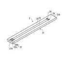
本実施形態に係るセンサ挿入・回収装置(センサ挿入及び回収装置)、及びモニタリング装置の第1の実施例を説明する。図1は、実施例1に係るモニタリング装置100の全体構成図である。モニタリング装置100は、検体中の対象成分の濃度に応じたセンサ信号(応答電流値)を生成する電気化学センサ(以下、単に「センサ」と称する)2が収容されるセンサ挿入・回収装置1と、センサ2からセンサ信号を受け取り、検体中の対象成分濃度を演算し、また、その演算結果を外部装置に送信する制御ユニット200とから構成されている。<Example 1>
A first example of the sensor insertion / recovery device (sensor insertion / recovery device) and the monitoring device according to the present embodiment will be described. FIG. 1 is an overall configuration diagram of a
図2は、実施例1に係るセンサ2の全体斜視図である。センサ2は、その先端側が患者の皮下に植え込まれて使用される皮下留置型の電気化学センサである。本実施例では、このセンサを、患者の皮下組織の細胞外に存在する間質液や血液等の体液に含まれるグルコース濃度(すなわち血糖値)を測定するためのグルコースセンサとして用いる場合を例として説明するが、これに限定されるものではない。 FIG. 2 is an overall perspective view of the
センサ2は、センサ基板21、センサ電極22、リード線23、コネクタ24を有している。センサ基板21は、可撓性を有しており、いわゆるフレキシブル薄膜センサである。更に、センサ基板21は、生体適合性及び絶縁性を有する材料を用いると良い。例えば、センサ基板21として、ポリプロピレン、ポリイミド、ポリエチレンテレフタレート、ポリエーテルエーテルケトン及びポリエチレンナフタレート等の樹脂を用いることができる。 The
センサ基板21は図示されるように細長い形状を有しており、その先端部21A側にはセンサ電極22が設けられている。センサ電極22は、センサ基板21の幅方向に隣接して2個設けられており、一方が作用極22Aで他方が対極22Bである。センサ電極22は、例えば蒸着、スパッタリング、印刷(スクリーン印刷、グラビア印刷)又は転写等により形成することができる。作用極22Aは、体液中の対象成分であるグルコースと電子授受を行う部分である。対極22Bは、作用極22Aとともに電圧印加に利用される電極である。作用極22A及び対極22Bには、リード線23の一端が接続されている。そして、リード線23の他端は、センサ基材21の基端部21B側に設けられたコネクタ24に接続されている。 The sensor substrate 21 has an elongated shape as shown in the figure, and a
作用極22Aの表面には試薬酵素が形成されている。この試薬酵素としては、例えばグルコースオキシダーゼ(GOD)、グルコースデヒドロゲナーゼ(GDH)等を好適に使用することができる。試薬酵素の固定化方法として、公知の種々の方法、たとえば重合性ゲル、ポリアクリルアミドやリンなどの高分子、リン脂質ポリマーにシランカップリング剤を導入したMPC重合体あるいはタンパク質膜を利用する方法を採用することができる。尚、センサ電極22を覆うように、センサ基板21上には検体たる間質液或いは血液を透過(浸透)させることの可能な外層膜(図示せず)に覆われても良い。この種の外層膜は、センサ電極22を保護するための保護膜としても機能する。 A reagent enzyme is formed on the surface of the working
センサ2は、生成したセンサ信号を、コネクタ24、ケーブル25、ケーブルコネクタ201を介して制御ユニット200に転送される。制御ユニット200には、電源202、制御装置203、送信機204、操作ボタン205が設けられている。制御装置203は、制御ユニット200及びセンサ2の作動状況を操作ボタン205の状態に応じて制御
するための電子制御ユニットである。制御装置203は、CPUの他、各種のプログラムを記憶するROM、RAM等を備えており、センサ2から入力されるセンサ信号に基づいてグルコース濃度を演算する。The
電源202は、センサ2に制御電力を供給する装置であり、制御装置203からの指令に基づいてセンサ電極22に電圧を印加する。センサ電極22間に電圧が印加されると、体液に含まれるグルコースと作用極22Aとの間で電子の授受が行われる。センサ2は、このようにして得られた応答電流値をセンサ信号として制御装置203に出力し、制御装置203はセンサ2から取得したセンサ信号に基づいて血糖値を演算する。制御装置203は必要に応じて、血糖値(グルコース濃度)の演算結果を、送信機204から外部の情報処理端末(例えば、パーソナルコンピュータ)に送信する。 The
センサ2は、グルコース濃度のモニタリング開始から所定のモニタリング期間(例えば、数日〜数週間程度)が経過するまでの間、皮下に留置された状態に維持される。なお、制御装置203の制御プログラムは、例えばモニタリング期間において所定間隔毎にグルコース濃度の測定処理を行うように設定されている。その他、制御ユニット200には、グルコース濃度の演算結果を表示するモニタや、演算した血糖値が異常値を示している際に警告音を発する警告手段が備えられても良い。 The
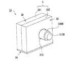
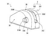
次に、本実施例に係るセンサ挿入・回収装置1について詳しく説明する。図3は、実施例1に係るセンサ挿入・回収装置1の外観斜視図である。センサ挿入・回収装置1は、センサ2、穿刺用薄板刃4等を収容する筐体であるハウジング3を備えている。 Next, the sensor insertion /
ハウジング3の下面3Aには、粘着テープ31が貼り付けられており(図1に図示し、図3では省略している)、この粘着テープ31によってハウジング3が患者の腹部や腕部等に固定される。従って、ハウジング3の下面3Aは、皮膚に貼付される貼付面ともいえる。なお、上述した制御ユニット100に関しては、ハウジング3と同様に粘着テープ等の固定手段によって皮膚に取り付けても良いし、患者のベルトやベルトループにフック等を介して取り付けるようにしても良い。 An adhesive tape 31 is affixed to the
ハウジング3は、第一ケース301と第二ケース302とからなる。第一ケース301及び第二ケース302は、上面3Bや下面3Aと平行な断面の形状が概略コ字状になっている。そして、図示のように第一ケース301及び第二ケース302が互いに連結されることで、その内部に収容空間が形成されると共に、上面3Bには収容空間と連通する開口部303が形成される。図示のように、上面3Bに形成された開口部303は細長で直線的な形状として設けられており、後述する薄板刃用つまみ50B(第一把持部)、センサ用つまみ51B(第二把持部)が開口部303の長手方向に沿ってスライド自在に挿入されている。以下、開口部303を「スライド開口部」と称する。本実施例ではスライド開口部303が本発明の操作用開口部に対応する。 The
図4は、ハウジング3の内部構造を説明するための説明図であり、便宜上、第二ケース302側を破線にて表す。ハウジング3の下面3Aには、下面開口部304が設けられている。なお、ハウジング3の下面3Aは、皮膚に貼付される貼付面ということができる。下面開口部304は、ハウジング3内に収容されている穿刺用薄板刃4及びセンサ2を皮膚側に向かって送出し、或いは、皮下に植え込まれた状態の穿刺用薄板刃4及びセンサ2をハウジング3内に個別回収する際に使用する用途の開口部である。下面開口部304は、センサ2を受け入れた穿刺用薄板刃4が円滑に通る程度の有効断面積を有する。図示の例では、下面開口部304は矩形をなしているが他の形状を採用しても良い。 FIG. 4 is an explanatory diagram for explaining the internal structure of the
ハウジング3の内部には、下面開口部304に連通する態様でガイド部としてのガイド
溝305が形成されている。図示のように、第一ケース301側に設けられた溝と、第二ケース302側に設けられた溝が組み合わさることで一つのガイド溝305が構成されている。この図において、ガイド溝305は矩形断面をなす細長溝として構成されている。ガイド溝305は、穿刺用薄板刃4を滑動自在(摺動自在ともいえる。以下、本明細書において共通)に支持する案内部材である。ガイド溝305及びスライド開口部303は、上下に互いに重なるように形成されている。なお、ここでの上下関係とは、ハウジング3の上面3B、下面3Aを水平面と仮定した場合を基準としている。Inside the
穿刺用薄板刃4(穿刺刃部材)は先端側の刃先部40が鋭利に尖った薄板の刃であり、例えば医療グレードのステンレス鋼等によって作製しても良い。穿刺用薄板刃4は、センサ2を皮下に挿入する際に皮膚に穿刺される。また、穿刺用薄板刃4は、ガイド溝305に沿って滑動された際に折れる等の破損が生じることのないように、ある程度の撓みが期待できるようにその厚さ等が規定されている。 The
穿刺用薄板刃4の後端部41(第一基準部位)には、穿刺刃操作部としての薄板刃ホルダ50が穿刺用薄板刃4と一体的に固定されている。薄板刃ホルダ50は、穿刺用薄板刃4の後端部41に接合される第一接合部50Aと、この第一接合部50Aの上に形成された薄板刃用つまみ50Bから構成されている。本実施例において、第一接合部50Aは四角柱形状を有し、薄板刃用つまみ50Bは円柱形状を有しているが、これらの形状の組合せには限定されない。また、薄板刃用つまみ50Bの直径はスライド開口部303の幅よりも僅かに小さく設定されており、薄板刃用つまみ50Bは、その上部がハウジング3の外部に露出するようにスライド開口部303へと挿通されている。 At the rear end portion 41 (first reference portion) of the puncture
図5は、穿刺用薄板刃4に対するセンサ2の受け入れ状態を説明する説明図である。図示のように、穿刺用薄板刃4上には、センサ2を摺動自在に受け入れる長溝43(凹部)が、穿刺用薄板刃4の長手方向に沿って設けられている。長溝43の幅、長手方向の長さはセンサ2の幅、及びその長さと等しいか、僅かに大きい寸法に設定されている。特に、長溝43の深さをセンサ2の厚さ以上の寸法とすることで、図示の白抜き矢印の方向から眺めた場合にセンサ2が長溝43から突出しないように構成されている。 FIG. 5 is an explanatory view for explaining a receiving state of the
センサ基板21においてセンサ電極22が形成されている面を「電極形成面21C」と称し、これに対向する面を「裏面21D」と称す。センサ基板21の裏面21Dが長溝43の底面43Aに接触し、電極形成面21Cが長溝43の開放面から露出するように、長溝43がセンサ2を受け入れ可能な態様で構成されている。また、センサ2の先端部21A側には、先端面が斜めに傾斜したテーパ部21Eが形成されている。テーパ部21Eは、センサ基板21の先端面が、長溝43の底面43Aと接触する裏面21Dと逆側の電極形成面21C(露出面)から裏面21D(接触面)にかけて基端部21B側に向かって傾斜している。なお、図1及び図2では、テーパ部21Eの図示を省略している。テーパ部21Eは図5に示すような曲面形状として形成する代わりに、傾斜平面として構成されても良い。 A surface of the sensor substrate 21 on which the
図5に示すように、センサ2における電極形成面21Cの基端部21B(第二基準部位)には、本発明におけるセンサ操作部としてのセンサホルダ51がセンサ2のセンサ基板21と一体的に固定されている。センサホルダ51は、センサ2の基端部21Bに接合される第二接合部51Aと、この第二接合部51Aの上に形成されたセンサ用つまみ51Bから構成されている。センサホルダ51においても、第二接合部51Aは四角柱形状を有し、センサ用つまみ51Bは円柱形状を有しているが、これらの形状に限定されるものではない。また、センサ用つまみ51Bの直径はスライド開口部303の幅よりも小さく設定され、センサ用つまみ51Bの上部は、スライド開口部303から外部に露出するようにスライド開口部303に挿通されている。そして、図4にも示されるように、薄板刃用
つまみ50Bとセンサ用つまみ51Bは、スライド開口部303の長手方向に沿って並んで配置されている。As shown in FIG. 5, a
次に、ガイド溝305の詳細について説明する。図4に示すように、ガイド溝305は、穿刺角度規定ガイド溝305Aと、スライド用ガイド溝305B(直線状ガイド部)とから構成されている。穿刺角度規定ガイド溝305Aは、ハウジング3の下面3Aに形成された下面開口部304に接続されており、ハウジング3の下面3Aに対して傾斜して配置される。スライド用ガイド溝305Bは、スライド開口部303が形成されたハウジング3の上面3Bと平行となるように直線状に形成されている。ガイド溝305のうち、下面開口部304に近い方の端部を「先端」とし、遠い方の端部を「後端」と規定する。ガイド溝305は、その先端側から穿刺角度規定ガイド溝305A、スライド用ガイド溝305Bの順で配置されており、双方は緩やかに接続されている。なお、第一ケース301と第二ケース302の組み合わせ作業は、穿刺用薄板刃4の両側面がガイド溝305に嵌め込まれた状態で行われる。 Next, details of the
センサ挿入・回収装置1が皮膚にセットされる前の初期状態においては、図3及び図4に示す状態となっている。センサ2は穿刺用薄板刃4の長溝43に嵌め込まれることで、受け入れられた状態にある。初期状態における薄板刃用つまみ50B及びセンサ用つまみ51Bの位置は、薄板刃ホルダ50と接合される穿刺用薄板刃4の後端部41が、ガイド溝305の後端側に位置するように、スライド開口部303の長手方向における後端側に配置されている(図4参照)。また、詳しくは後述するが、ユーザーがセンサ挿入・回収装置1を使用する際に、薄板刃用つまみ50Bとセンサ用つまみ51Bをスライド開口部303の長手方向に沿ってスライドさせる。そのため、スライド開口部303は、皮膚に固定される下面3A以外の面であって、かつ、スライド用ガイド溝305Bの仮想軸線が貫通しない面に形成されると良い。本実施例では、そのような面の一例としてハウジング3の上面3Bにスライド開口部303を設けている。 In the initial state before the sensor insertion /
次に、センサ挿入・回収装置1の動作について説明する。センサ挿入・回収装置1は、モニタリング装置100による対象成分のモニタリングに際して、センサ2を経皮的に皮下に植え込み、かつ、モニタリング期間の終了後には使用済みのセンサ2を再びハウジング3から回収する用途で使用される。図6は、センサ挿入・回収装置1を使用する手順を示すフローチャートである。センサ2の挿入・回収方法(挿入及び回収方法)はこのフローチャートに記載された一部のステップとして記載されている。 Next, the operation of the sensor insertion /
ユーザーは、まず、ハウジング3の下面3Aに貼付されている粘着テープ31の剥離フィルム(図示せず)を剥がし、皮膚上における所定位置にハウジング3を配置する。そして、ハウジング3を皮膚に軽く押しつけることにより、ハウジング3を皮膚に固定する(ステップS101:設置工程)。この状態において、センサ挿入・回収装置1は図3、4に示す初期状態にある。初期状態においては、図5に示すように、薄板刃ホルダ50の第一接合部50Aにおける第一当接面P1と、センサホルダ51の第二接合部51Aにおける第二当接面P2が互いに当接している。 The user first peels off the release film (not shown) of the adhesive tape 31 attached to the
次いで、ユーザーは、薄板刃ホルダ50の薄板刃用つまみ50Bを把持し、スライド開口部303の長手方向に沿って、後端側から前端側に向かう方向(以下、この方向を「第一方向」と称する)にスライドさせる(ステップS102:センサ挿入工程)。そうすると、薄板刃用つまみ50Bのスライド動作に連動して、穿刺用薄板刃4がガイド溝305を後端側から先端側に向かって滑動する。その際、センサホルダ51(第二接合部51A)側の第二当接面P2が、薄板刃ホルダ50(第一接合部50A)側の第一当接面P1によって押されるため、穿刺用薄板刃4の長溝43に受け入れられた状態のセンサ2も受動的に動作する。その結果、穿刺用薄板刃4を、センサ2と一体的にガイド溝305の先端
側に向かって滑動させることができる。Next, the user grips the
穿刺用薄板刃4の刃先部40が下面開口部304から皮膚側に送出されると、穿刺用薄板刃4が皮膚に穿刺され、穿刺用薄板刃4の長溝43に嵌っているセンサ2も皮下に植え込まれる。図5で説明したように、センサ2は長溝43からその厚さ方向に突出していないため、センサ2の挿入時に該センサ2が皮下組織等に引っ掛かるなどによってセンサ2が折れ曲がることがない。また、皮膚に対する穿刺用薄板刃4の穿刺角度は、穿刺角度規定ガイド溝305Aとハウジング3の下面3Aとがなす角度によって決まる。そのため、本実施例では、穿刺用薄板刃4の穿刺角度が所定の目標穿刺角度となるように穿刺角度規定ガイド溝305Aと下面3Aとがなす角度が予め調節されている。 When the
図4に示すように、ハウジング3内側の側面には、第一スライド規制部61及び第二スライド規制部62が設けられている。これらの規制部61,62は、センサ用つまみ51B及び薄板刃用つまみ50Bがスライドする際の可動範囲を規定、調整するための部材である。ユーザーが薄板刃用つまみ50Bを把持して第一方向にスライドさせてゆくと、センサホルダ51の第二接合部51A(より詳しくは、第二接合部51Aにおける第二当接面P2とは逆側の面)に当接し、センサ用つまみ51Bのそれ以上の第一方向へのスライド動作を規制する。そうすると、センサホルダ51側の第二当接面P2と薄板刃ホルダ50側の第一当接面P1が互いに干渉し、薄板刃用つまみ50Bの第一方向へのスライド動作が規制されるようになる。その結果、穿刺用薄板刃4がハウジング3から送出されなくなり、刃先部40が皮膚にそれ以上深く潜り込まなくなる。 As shown in FIG. 4, a first
そこで本実施例では、第一スライド規制部61によって薄板刃用つまみ50Bの第一方向への規制が開始される時点、即ち、センサ用つまみ51Bが第一スライド規制部61に当接する時点で、センサ2のセンサ電極22がちょうど目標挿入深さに到達するように、第一スライド規制部61を設置するようにした。これにより、ユーザーは、第一スライド規制部61によって規制されるようになるまで、薄板刃用つまみ50Bをスライドさせることで、センサ電極22を目標挿入深さまで確実に到達させることができる。 Therefore, in this embodiment, when the first
図7は、穿刺用薄板刃4の穿刺が完了した状態を示す。この状態においては、センサ2のセンサ電極22が所定の目標挿入深さに配置されている。なお、本実施例では、第一スライド規制部61をセンサホルダ51と当接させることで、間接的に薄板刃ホルダ50の第一方向へのスライド動作を規制しているが、薄板刃ホルダ50のスライド動作を直接的に規制するように構成しても良い。例えば、センサ電極22が目標挿入深さに到達するようなタイミングで薄板刃ホルダ50と当接するような位置に第一スライド規制部61を設置しても良い。 FIG. 7 shows a state where the puncture of the puncture
また、図5に示すように、センサホルダ51の第二接合部51Aの側面(第二当接面P2と直交する面)には、ハウジング3の内壁面に向かって付勢される係止ピン52が形成されている。より詳しくは、図8A、8Bに示すように、第二接合部51Aの側面には係止ピン52を収容する収容凹部53が形成されており、収容凹部53と係止ピン52の底面同士がバネ部材54(弾性部材)を介して接合されている。図8Aは、薄板刃用つまみ50Bを第一方向にスライドさせる際に、センサ用つまみ51Bが第一スライド規制部61に当接する前の状態を表し、図8Bは、センサ用つまみ51Bが第一スライド規制部61にちょうど当接する時点の状態を表す。 In addition, as shown in FIG. 5, a locking pin that is biased toward the inner wall surface of the
図8Aに示すように、センサ用つまみ51Bが第一スライド規制部61に当接する前は、係止ピン52がハウジング3の内壁面3Cに押圧されることにより、係止ピン52が収容凹部53に収容された状態となる。従って、センサホルダ51は、係止ピン52の頂部を内壁面3Cに摺接させながら、薄板刃ホルダ50の動きに追従してスライドする。また
、ハウジング3の内壁面3Cのうち、センサ用つまみ51Bが第一スライド規制部61に当接する時点で係止ピン52が相対するような位置に、係止ピン52を嵌合する係止孔30が設けられている(図8B参照)。そのため、薄板刃用つまみ50Bが第一スライド規制部61に当接するタイミングにて、係止ピン52が係止孔30に係止される。As shown in FIG. 8A, the locking
次に、ユーザーは、薄板刃ホルダ50の薄板刃用つまみ50Bのみを把持し、スライド開口部303の長手方向に沿って、第一方向とは逆方向(以下、「第二方向」という)にスライドさせる(ステップS103:センサ回収工程)。その際、係止ピン52は係止孔30に係止されているため、薄板刃ホルダ50がセンサホルダ51から離反する方向にスライドすることで、穿刺用薄板刃4の長溝43に対するセンサ2の嵌合状態が解除される。 Next, the user holds only the thin
特に、図5に示したように、センサ2の先端面にはテーパ部21Eが形成されているため、ユーザーが薄板刃用つまみ50Bを第二方向、つまり薄板刃ホルダ50の第一当接面P1をセンサホルダ51の第二当接面P2から離反する方向にスライドさせると、センサ2におけるテーパ部21Eが長溝43の縁上に乗り上がり易くなる。このようにして、穿刺用薄板刃4の長溝43に対してセンサ2を摺動させながら容易にこれらを分離させることができる。 In particular, as shown in FIG. 5, since the tapered portion 21 </ b> E is formed on the distal end surface of the
その結果、穿刺用薄板刃4がセンサ2から分離した状態でガイド溝305をその後端側に向かって滑動し、センサ2は皮下に留置された状態で穿刺用薄板刃4のみが皮下から引き抜かれる。その際、センサホルダ51に形成された係止ピン52や、センサ2の先端面に形成されたテーパ部21Eの働きによって、センサ2が穿刺用薄板刃4に追従して引き抜かれることが防止される。そのため、センサ電極22の挿入深さが目標挿入深さからずれることが無い。図9は穿刺用薄板刃4の回収が完了した状態を示す図である。即ち、この状態では、刃先部40が下面開口部304からハウジング3内部へと回収され、センサ2のみが皮下に留置された状態にある。 As a result, the
なお、ステップS103において、薄板刃用つまみ50Bを第二方向にスライドさせてゆくと、最終的には図4に示した第二スライド規制部62が薄板刃ホルダ50の第一接合部50A(より詳しくは、第一接合部50Aにおける第一当接面P1とは逆側の面)に当接する。その時点で、センサ用つまみ51Bにおける第二方向へのスライド動作が規制されるようになり、ガイド溝305の後端側に向けての穿刺用薄板刃4の滑動も停止する。そのため、第二スライド規制部62の設置位置は、第二スライド規制部62が薄板刃ホルダ50の第一接合部50Aに当接する時点において穿刺用薄板刃4の刃先部40が完全にハウジング3内部に収容されるように調節されている。 In step S103, when the
センサ用つまみ51B及び薄板刃用つまみ50Bがスライド可能な可動範囲はスライド開口部303の縁部によって制限することができる。そのため、第一スライド規制部61及び第二スライド規制部62を設置する代わりに、スライド開口部303の縁部の位置を調節することで、上記可動範囲を調整しても良い。例えば、センサ電極22が目標挿入深さにちょうど到達するタイミングで薄板刃ホルダ50がスライド開口部303の前端側の縁部に当接するように調整しても良い。 The movable range in which the
次に、ユーザーは、制御ユニット200を用いて、患者の体液に含まれる血糖値のモニタリングを行う(ステップS104)。制御ユニット200の操作ボタン205におけるモニタリング開始ボタンが押下されると、制御装置203は、所定間隔毎にセンサ2のセンサ信号に基づいてグルコース濃度を演算し、血糖値をモニタリングする。モニタリング期間が経過すると、制御ユニット200のモニタにモニタリング期間が終了したことを示す内容の情報が表示される。 Next, the user uses the
血糖値のモニタリングが終了すると、ユーザーは、センサホルダ51のセンサ用つまみ51Bを把持し、スライド開口部303の長手方向に沿って第二方向にスライドさせる(ステップS105:センサ回収工程)。図8(b)に示すように、係止ピンの頂部には、先端に向かって徐々に縮径する縮径部52Aが形成されている。従って、ユーザーがセンサ用つまみ51Bをスライドさせようとすれば、縮径部52Aの幾何学的な形状効果により、係止孔30に対する係止ピン52の係止状態が解除される。その結果、センサ2は、センサ用つまみ51Bのスライド動作に連動して皮下から引き抜かれ、下面開口部304からハウジング3内部へと回収される(図3参照)。なお、係止ピン52における縮径部52Aの形状やその大きさは、ユーザーがセンサ用つまみ51Bを把持して第二方向にスライドさせようとすれば係止ピン52が係止孔30から容易に外れるが、薄板刃用つまみ50Bを第二方向にスライドさせた際には係止ピン52が係止孔30から外れないように調節されている。 When the monitoring of the blood glucose level is completed, the user holds the
以上のように、本実施例に係るセンサ挿入・回収装置1において、薄板刃ホルダ50は、穿刺用薄板刃4をガイド溝305に沿って滑動させ、かつ、その滑動方向に応じて、下面開口部304からの穿刺用薄板刃4の穿刺と、穿刺用薄板刃4の回収を選択的に行う。そして、穿刺用薄板刃4の穿刺に際して、穿刺用薄板刃4をセンサ3と一体的にガイド溝305に沿って滑動させることでセンサ2のセンサ電極22を皮下に挿入する一方、穿刺用薄板刃4をセンサ3から分離させた状態でガイド溝305を滑動させることで穿刺用薄板刃4をハウジング3内部に回収する。そして、センサホルダ51は、センサ電極22が皮下に挿入された状態のセンサ2を引き抜いて下面開口部304からハウジング3内部に回収する。 As described above, in the sensor insertion /
このように構成されるセンサ挿入・回収装置1によれば、センサ2を皮下の所定の深さに挿入するための機構、及びモニタリング終了後にはセンサ2を皮下から回収するための一切の機構がハウジング2内に一体的に集約されるので、ユーザーの利便性を向上することができる。特に、センサ2の皮下への挿入が終了した後、目的物質のモニタリングを開始する前における器具類の付け替えが不要であるため、使い勝手が良く、また、取り扱い者による人為的ミス(ヒューマンエラー)が起こる確率も低減できる。 According to the sensor insertion /
また、穿刺用薄板刃4及びセンサ2のハウジング3から皮下への挿入と、皮下からハウジング3内部への回収は、ハウジング3が皮膚に貼付される面(下面3A)に形成された下面開口部304のみを介して行われるため、穿刺用薄板刃4及びセンサ2がユーザーに接触することがない。従って、センサ2を皮下に挿入した後に穿刺用薄板刃4をハウジング3内に回収する際や、血糖値のモニタリングの終了後にセンサ2をハウジング3内に回収する際に、医師等の第三者が患者の体液に接触して感染する虞がない。従って、このような感染を防止するための別途の対策を講ずる必要もなく、ユーザーの利便性及び安全性を向上することができる。また、穿刺用薄板刃4が外部に露出しないので、ユーザーが負傷したり、心理的な不快感をユーザーが受けることも無い。 Further, the insertion of the
<実施例2>
次に、センサ挿入・回収装置の第2の実施例を説明する。実施例1では、センサ用つまみ51B及び薄板刃用つまみ50Bをスライド動作させる所謂スライド機構を採用したが、本実施例では巻き取り機構を採用する。図10は、実施例2に係るセンサ挿入・回収装置1Aの外観斜視図である。図11は、ハウジング3の内部構造を説明するための図であり、便宜上、第二ケース302側の図示は割愛している。本実施例のセンサ挿入・回収装置1Aにおいて、実施例1と同様の部材については同じ符号を付すことで詳細な説明は割愛する。<Example 2>
Next, a second embodiment of the sensor insertion / recovery device will be described. In the first embodiment, a so-called slide mechanism that slides the
ハウジング3内部に形成されるガイド溝305は、穿刺角度規定ガイド溝305Aと、中心軸axを中心として円弧状に形成された巻き取り用ガイド溝305C(円弧状ガイド部)とから構成されている。また、ハウジング3には、薄板刃ホルダ500(穿刺刃操作部)とセンサホルダ510(センサ操作部)が軸支されており、それぞれが中心軸axを中心に回動自在に設けられている。 The
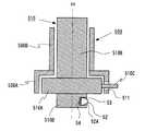
図12及び図13は、薄板刃ホルダ500及びセンサホルダ510の構造を説明するための図である。図12は外観斜視図、図13は断面構造を示す図である。なお、図12及び図13において、センサ2及び穿刺用薄板刃4の図示を省略している。 12 and 13 are views for explaining the structure of the
センサホルダ510は、ベース部510A、センサ用つまみ510B、センサ接合用片510C、係止用ピン保持部510Dを含む。ベース部510A、センサ用つまみ510B、係止用ピン保持部510Dの各々は、その軸線が中心軸axに一致する円柱状部材である。センサ用つまみ510B及び係止用ピン保持部510Dは、ベース部510Aに比べて一段細径に形成されている。センサ接合用片510Cは、センサ2の基端部21B(第二基準部位)に接合される。係止用ピン保持部510Dには収容凹部53が形成されており、バネ部材54及び係止ピン52が収容されている。 The
また、薄板刃ホルダ500は、センサホルダ510のベース部510Aとセンサ用つまみ510Bの外周側を覆うように筒状に形成されている。薄板刃ホルダ500は、ベース部510Aの外周を覆う円筒状のベース筒部500A、薄板刃用つまみ500B、薄板刃接合用片500Cを含んでいる。薄板刃用つまみ500Bは、ベース筒部500Aより縮径されてセンサ用つまみ510Bの外周を覆う円筒状の部材である。薄板刃接合用片500Cは、ベース筒部500Aと一体に形成されて穿刺用薄板刃4の後端部41(第一基準部位)に接合される部材である。 Further, the
センサ用つまみ510B及びその外周側に位置する薄板刃用つまみ500Bは、同心状に配置されており、かつ、センサ用つまみ510Bの先端側は薄板刃用つまみ500Bの先端側から突出している。また、ベース筒部500Aには、その内側に配置されるベース部510Aから径方向に突設されたセンサ接合用片510Cを挿通させるための細長孔511が、ベース筒部500Aの周方向に沿って形成されている。この細長孔511は、ベース筒部500Aの周方向の例えば4分の3周程度の範囲に亘って形成されているが、この範囲は適宜変更できる。また、薄板刃接合用片500Cは、ベース筒部500Aにおける細長孔511の縁部付近から径方向に突設されている。 The
図10に示すように、ハウジング3の側面3Dには、円形の操作用開口部313が形成されている。センサ用つまみ510B及び薄板刃用つまみ500Bは、この操作用開口部313に挿通されることで各々の先端側がハウジング3の外部に露出している。但し、操作用開口部313の形状は、上記の例に限定されるものではない。また、詳しくは後述するが、ユーザーがセンサ挿入・回収装置1Aを操作する際には、操作用開口部313を介してハウジング3の外部に突出する薄板刃用つまみ500Bとセンサ用つまみ510Bを回動操作する構成上、操作用開口部313は、皮膚に固定される下面3A以外の面であって、かつ、巻き取り用ガイド溝305Cの中心軸axが貫通する面に設けるようにしている。 As shown in FIG. 10, a circular operation opening 313 is formed on the
センサ挿入・回収装置1Aにおけるセンサ2及び穿刺用薄板刃4は実施例1において説明したものと同等である。初期状態において、センサ2は穿刺用薄板刃4の長溝43に摺動自在に受け入れられている。また、穿刺用薄板刃4は、先端側から穿刺角度規定ガイド溝305Aと、巻き取り用ガイド溝305Cとから構成されるガイド溝305に滑動自在に支持されている。薄板刃ホルダ500の薄板刃用つまみ500Bを回動させることによ
って、穿刺用薄板刃4をガイド溝305(穿刺角度規定ガイド溝305A及び巻き取り用ガイド溝305C)に沿って滑動させることができ、その滑動方向に応じて、下面開口部304を通じた穿刺用薄板刃4の穿刺と、その回収とが選択的に行われる。本実施例では、薄板刃用つまみ500Bを反時計廻り(第一方向)に回動させると、巻き取り用ガイド溝305Cへの穿刺用薄板刃4の巻き取り量が減り、薄板刃用つまみ500Bを時計廻りに回動させると、穿刺用薄板刃4の上記巻き取り量が増える。The
次に、センサ挿入・回収装置1の動作について説明する。ユーザーは、まず、ハウジング3を皮膚上の所定位置に配置する(設置工程)。この状態において、センサ挿入・回収装置1Aの外観は図10に示す初期状態にある。次いで、ユーザーは、薄板刃用つまみ500Bを反時計廻り(第一方向)に回動させる(センサ挿入工程)。そうすると、細長孔511の縁部511Aに当接するセンサ接合用片510Cも連動して反時計回りに回動し、穿刺用薄板刃4の長溝43に受け入れられているセンサ2も受動的に動作する。その結果、穿刺用薄板刃4は、センサ2と一体的にガイド溝305の先端側に向かって滑動する。そして、刃先部40が下面開口部304から送出されることで穿刺用薄板刃4が皮膚に穿刺されると共に、穿刺用薄板刃4に受け入れているセンサ2も皮下に挿入される。 Next, the operation of the sensor insertion /
図11、12に示す第一回動規制部610及び第二回動規制部620は、センサ用つまみ51B及び薄板刃用つまみ500Bの回動可能範囲を規定するための部材であり、ハウジング3と一体に設けられている。この第一回動規制部610は、ユーザーが薄板刃用つまみ500Bを把持して反時計廻り(第一方向)に回動させてゆくと、センサホルダ510におけるセンサ接合用片510Cが第一回動規制部610に当接する。これによって、センサ用つまみ51Bのそれ以上の第一方向への回動動作が規制される。そうすると、細長孔511の縁部511Aがセンサ接合用片510Cと干渉して、薄板刃用つまみ500Bの反時計廻りの回動動作が規制される。即ち、薄板刃ホルダ500の回動動作が、センサホルダ510を介して間接的に第一回動規制部610によって規制される。その結果、穿刺用薄板刃4がハウジング3から送出されなくなり、刃先部40が皮膚にそれ以上深く潜り込まなくなる。 The first
第一回動規制部610は、センサ電極22が目標挿入深さに到達する時点でセンサ接合用片510Cが第一回動規制部610に当接するような位置に設けられている。これにより、ユーザーは、第一回動規制部610によって規制されるようになるまで、薄板刃用つまみ50Bを反時計廻りに回動させることで、センサ電極22を目標挿入深さまで確実に到達させることができる。そして、センサ電極22が目標挿入深さに到達した後は、センサ電極22がそれ以上深く挿入されることがない。その結果、センサ電極22を目標挿入深さに対して過不足なく挿入することができる。 The first
センサ挿入・回収装置1Aにおけるハウジング3の内壁面3Cには、実施例1に係るセンサ挿入・回収装置1と同様に、係止ピン52を係止するための係止孔30が形成されている。図8を参照すると、本実施例では図中の符号51Aを符号510D(係止用ピン保持部)に置き換える。ハウジング3内において、係止用ピン保持部510Dの周囲に位置する内壁面3Cは、係止用ピン保持部510Dの円柱状側面を覆うように筒状に形成されている。そして、薄板刃用つまみ500Bを反時計廻りに回動させた際に、センサ用つまみ510Bが第一回動規制部610にちょうど当接する時点で係止ピン52が係止孔30に嵌合するような位置に係止孔30が設けられている。 A locking
これによれば、センサ用つまみ510Bが第一回動規制部610に当接するまで、係止用ピン保持部510Dは、係止ピン52の頂部を内壁面3Cに摺接させながら回動する。そして、センサ用つまみ510Bが第一回動規制部610に当接した時点で係止ピン52が係止孔30に嵌合する。図14A、14Bは、穿刺用薄板刃4の穿刺が完了した状態を
示す。この状態において、センサ2のセンサ電極22は所定の目標挿入深さに配置されている。According to this, until the
次いで、ユーザーは、薄板刃ホルダ500の薄板刃用つまみ500Bのみを把持し、薄板刃用つまみ500Bを時計廻りに回動させる(穿刺刃回収工程)。そうすると、薄板刃用つまみ500Bと一体のベース筒部500Aも時計廻りに回動する。今度は逆に、細長孔511の縁部511Aがセンサ接合用片510Cから離反してゆくため、これらが互いに干渉することはない。ここで、センサホルダ510側に設けられている係止ピン52は係止孔30に係止されている。そのため、薄板刃用つまみ500Bが時計廻りに回動すると、穿刺用薄板刃4の長溝43をセンサ2が摺動することで、長溝43に対するセンサ2の嵌合状態が解除される。その結果、穿刺用薄板刃4がセンサ2から分離した状態でガイド溝305を滑動し、センサ2が皮下に留置された状態で穿刺用薄板刃4のみが皮下から引き抜かれる。 Next, the user holds only the
薄板刃用つまみ500Bを時計方向に回動させてゆくと、最終的には薄板刃ホルダ500の薄板刃接合用片500Cが第二回動規制部620に当接する。そして、薄板刃接合用片500Cが第二回動規制部620に当接した時点で、センサ用つまみ510Bにおける時計方向への可動動作が規制(禁止)される。その結果、ガイド溝305における穿刺用薄板刃4の滑動は停止する。第二回動規制部620の設置位置は、第二回動規制部620が薄板刃ホルダ500の薄板刃接合用片500Cに当接する時点において、穿刺用薄板刃4の刃先部40が完全にハウジング3内部に収容されるように調節されている。図15は、本実施例において穿刺用薄板刃の回収が完了した状態を示す図である。即ち、この状態では刃先部40が下面開口部304からハウジング3内部に回収されて、センサ2のみが皮下に留置された状態を表している。なお、図14及び図15においても、便宜上、第二ケース302側の図示を省略している。 When the thin
次に、ユーザーは、制御ユニット200を用いて、患者の体液に含まれる血糖値のモニタリングを行う。そして、モニタリングが終了すると、ユーザーは、センサホルダ510のセンサ用つまみ510Bを把持し、時計廻りに回動させる(センサ回収工程)。係止ピン52の頂部には、実施例1と同様に縮径部52Aが形成されている。そのため、センサ用つまみ510Bに対して時計廻りの回転力が作用することで、係止孔30と係止ピン52の係止状態が解除される。その結果、センサ2は、センサ用つまみ510Bの回動動作に連動して皮下から引き抜かれ、下面開口部304からハウジング3内部へと回収される(図11参照)。 Next, the user uses the
以上のように、本実施例に係るセンサ挿入・回収装置1Aでは、実施例1と同様の作用効果を奏する上に、いわゆる巻き取り機構を採用することで装置をよりコンパクトにすることができる。 As described above, in the sensor insertion /
<実施例3>
次に、第3の実施例を説明する。図16〜図18は、実施例3に係るセンサ挿入・回収装置1Bの外観斜視図である。本実施例に係るセンサ挿入・回収装置1Bにおいて、実施例1及び2と同等の部材については同じ符号を付すことで詳細な説明は割愛する。本実施例のセンサ挿入・回収装置1Bは、皮膚に対する穿刺用薄板刃4の穿刺角度を変更可能であることを特徴とし、その他の点については実施例2に係るセンサ挿入・回収装置1Aと概ね同等である。<Example 3>
Next, a third embodiment will be described. 16 to 18 are external perspective views of the sensor insertion /
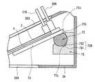
ハウジング3の下面3Aには、下面開口部314が形成されている。下面開口部314は、実施例1及び2に係る下面開口部304よりも相対的に大きいが、センサ2及び穿刺用薄板刃4の皮下への挿入や回収を行うための開口部であるという点で下面開口部304
と同様の機能を有する。なお、本実施例において下面開口部314の面積を増大させたのは、穿刺角度を変更しても穿刺用薄板刃4が下面開口部314と干渉することを回避するためである。A
Has the same function. The reason why the area of the
図19及び図20は、ハウジング3の内部構造を説明するための図であり、便宜上、第二ケース302側の図示は割愛している。ハウジング3内部には、ガイドレールホルダ350が、ハウジング3の側面3Dと、これと対向する側面3Eに揺動自在に軸支されている。ガイドレールホルダ350の揺動軸は、薄板刃ホルダ500及びセンサホルダ510の回動軸である「中心軸ax」と同軸である。ガイドレールホルダ350は、略C字型に形成されるガイド本体部351と、このガイド本体部351に一体に形成された棒状の操作レバー352を有する。ガイド本体部351の内周側には、穿刺用薄板刃4を滑動自在に支持するガイドレール353(円弧状ガイド部)が中心軸axを中心として円弧状に形成されている。 19 and 20 are diagrams for explaining the internal structure of the
側面3D及び側面3Eに挟まれている側面と、上面3Bとの境界部は双方の面を緩やかに接続するように曲面状に形成されており、この境界部には細長形状の開口部(以下、「揺動操作用開口部」と称す)355が形成されている。操作レバー352は、ガイド本体部351から中心軸axとの直交する方向に向かって延伸しており、その先端側が揺動操作用開口部355に挿通されることでハウジング3の外部に臨んでいる。また、薄板刃ホルダ500及びセンサホルダ510については、実施例2におけるものと同等である。また、センサ2の皮下への挿入、及びその回収に係る基本操作は実施例2において説明した通りであり、ここでは省略する。 The boundary between the side surface sandwiched between the
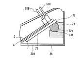
ガイドレールホルダ350は、予め定められた範囲で揺動可能である。そして、ユーザーが、図19における矢印A方向又はB方向に操作レバー352を操作することで、中心軸axに対するガイドレールホルダ350の揺動角度を変更することができる。ガイドレールホルダ350の停止位置は、例えば揺動停止位置A、B、C・・・のように、予め段階的に設定しておくことができる。そして、ハウジング3には、ガイドレールホルダ350の揺動角度が、設定された揺動停止位置A、B、C・・・の何れかに対応する角度となったときに自動的にガイドレールホルダ350をロック、即ち、ガイドレールホルダ350をその位置に停止させるロック機構(図示せず)が設けられている。更に、このロック機構は、例えばロック解除ボタンを押下する等の操作に応じて上記ロック状態を解除する機能を有する。 The
本実施例においては、ガイドレールホルダ350が穿刺角度調整手段に対応している。そして、ガイドレールホルダ350の揺動停止位置を変更することにより、穿刺用薄板刃4における皮膚への穿刺角度を変更可能となる。なお、本明細書において「穿刺角度」とは、皮膚に貼付されるハウジングの下面と、皮膚に穿刺される穿刺用薄板刃4とがなす角度として定義される。図21A〜Cは、穿刺角度を40°、60°、90°に調整してセンサ2を皮下に挿入した各状態を示す。なお、各図に示す穿刺角度の設定はあくまでも例示であり、角度の大きさ、設定数などは適宜変更しても良い。また、ここでは、ガイドレールホルダ350の揺動停止位置を複数設定することで穿刺用薄板刃4の穿刺角度を段階的に調整しているが、無段階に調整することも可能である。 In this embodiment, the
ところで、穿刺用薄板刃4の穿刺角度が小さいほど皮膚に緩やかに穿刺用薄板刃4及びセンサ2が皮下へと挿入される。そのため、同一種類のセンサ2を使用する場合、穿刺角度を調整することにより、センサ電極22の挿入深さを調整することができる。一方、血糖値のモニタリングにおいては、センサ2の挿入深さを深くした方が、センサ電極に対してグルコースをコンタクト(接触)させやすく、モニタリング結果の信頼性が高いといえる。しかしながら、センサ2の挿入深さを深くするという事は、穿刺用薄板刃4を皮下の
より深部まで穿刺する事を意味しており、穿刺時における痛み緩和の観点からはセンサ2の挿入深さをなるべく浅くしたいという要請もある。これに対して、本実施例におけるセンサ挿入・回収装置1Bは穿刺用薄板刃4の穿刺角度を調整できるため、モニタリング結果の信頼性と穿刺時における痛み緩和の双方のバランスを図ることができる。By the way, as the puncture angle of the puncture
また、患者が穿刺時に感じる痛みの度合いは穿刺深さが同じであっても個人差がある。例えば、皮下脂肪が少ない患者と多い患者とを比較すると、後者の方が穿刺時における痛みを感じにくいと考えられる。また、穿刺時における痛みを感じ易い患者もいれば、感じにくい患者もいる。従って、本実施例のセンサ挿入・回収装置1Bを用いて患者の個人差に応じて穿刺用薄板刃4の穿刺角度を調整することにより、従来は画一的だったセンサの挿入作業を、患者の個人差を配慮して行うことができる。 In addition, the degree of pain that a patient feels during puncture varies among individuals even if the puncture depth is the same. For example, when comparing patients with low subcutaneous fat and patients with high subcutaneous fat, the latter is considered less likely to feel pain during puncture. Some patients feel pain at the time of puncture, while others are difficult to feel. Therefore, by adjusting the puncture angle of the
また、センサ電極22の面積が大小異なる複数種類のセンサがラインナップとして用意される場合がある。センサ電極22が大きいセンサを使用する場合、センサ電極22が小さいセンサを使用する場合に比べて体液中のグルコースとセンサ電極がコンタクトしやすい。従って、モニタリング結果の信頼性を担保しつつ穿刺角度をより小さくすることができ、穿刺時における痛みの緩和を促進することができる。また、コレステロールや乳酸等、グルコース以外の成分をセンサで検出しようとした場合には、検出対象に応じて最適な挿入深さがそれぞれ相違する場合がある。これに対してセンサ挿入・回収装置1Bによれば、穿刺用薄板刃4の穿刺角度を調整することによりセンサの挿入深さを調整できるので、センサの目標挿入深さの変更に柔軟に対応することができる。 In addition, a plurality of types of sensors having
なお、ガイドレールホルダ350(穿刺角度調整手段)による穿刺用薄板刃4の穿刺角度の調整は、センサ2を皮下に挿入する前に事前に行うと良い。この場合、本実施例におけるセンサの挿入・回収方法において、センサ2を挿入する工程(センサ挿入工程)の前に、ハウジング3に対するガイドレールホルダ350の揺動停止位置を変更して、穿刺用薄板刃4の穿刺角度を調整する工程(穿刺角度調整工程)が行われる。 The puncture angle of the puncture
<実施例4>
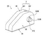
次に、第4の実施例を説明する。図22は、実施例4に係るセンサ挿入・回収装置1Cの外観斜視図である。図23は、実施例4に係るセンサ挿入・回収装置1Cの内部構造図である。図23は、センサ挿入・回収装置1Cの縦断面を表す。また、図24は、図23の部分拡大図である。本実施例に係るセンサ挿入・回収装置1Cにおいて、実施例1〜3と同等の部材については同じ符号を付すことで詳細な説明は割愛する。センサ挿入・回収装置1Cは、実施例3で説明したような、穿刺用薄板刃4の穿刺角度を変更可能な機構を備える。本実施例では、このような穿刺角度を変更可能な機構を、実施例1と同様なスライド式のセンサ挿入・回収装置に適用する例を説明する。<Example 4>
Next, a fourth embodiment will be described. FIG. 22 is an external perspective view of the sensor insertion /
以下、本実施例におけるセンサ挿入・回収装置1Cの構成のうち、実施例1に係るセンサ挿入・回収装置1との相違点を中心に説明する。センサ挿入・回収装置1Cは、ハウジング3の上面Bが、後面3G側から前面3F側に向かって前下がりに傾斜している。ハウジング3の内部には、図5に示すものと実質的に同等のセンサ2及び穿刺用薄板刃4等からなるユニットが収容されている。上面3Bには、実施例1と同様に、スライド開口部303が形成されている。スライド開口部303には、薄板刃用つまみ50B及びセンサ用つまみ51Bが挿通されおり、ユーザーは薄板刃用つまみ50B及びセンサ用つまみ51Bをスライド操作することで、センサ2及び穿刺用薄板刃4の皮下への挿入及び皮下からの回収を行う。 Hereinafter, of the configuration of the sensor insertion /
センサ挿入・回収装置1Cは、穿刺用薄板刃4を皮膚に穿刺する際の穿刺角度を変更可能な穿刺角度調節機構を備える。この穿刺角度調節機構は、角度調節用つまみ71、軸部
材72、軸受け部材73等を有する。軸受け部材73は、ハウジング3の後面3Gの内側に固定されている。角度調節用軸部72は、円柱部材の周面の一部を平面状とした形状を呈する軸部材である。角度調節用軸部72の周面のうち、平面状の部分を平面部72aと称し、曲面状の部分を曲面部72bと称する。角度調節用軸部72の曲面部72bには、ちょうど平面部72aの反対側の位置に突起状の凸部72cが設けられている。この凸部72cは、角度調節用軸部72の材軸方向に沿って形成されている。The sensor insertion /
軸受け部材73は、角度調節用軸部72を回転自在に軸受けする部材である。軸受け部材73は、角度調節用軸部72の曲面部72bを摺動可能に支える軸受け面73aを有する。軸受け面73aの一部には、角度調節用軸部72の曲面部72bに形成された凸部72cが嵌合する凹部730(第1凹部731、第2凹部732)が形成されている。軸受け部材73は、ハウジング3における一方の側方内面の内壁から他方の側方内面に至るまで、全幅範囲に亘って形成されている。図23,図24に示すように、角度調節用軸部72は、その曲面部72bが軸受け面73aに接した状態で軸受け部材73に支えられている。また、角度調節用軸部72の凸部72cは、第1凹部731及び第2凹部732の何れかに嵌合されるようになっており、図24に示す例では第1凹部731に凸部72cが嵌合されている。 The bearing
角度調節用軸部72の一端側には、角度調節用つまみ71が取り付けられている。角度調節用つまみ71及び角度調節用軸部72の軸心は一致している。図22に示すように、角度調節用つまみ71は円柱形状を有し、ハウジング3の側面3Dに形成された円形の操作用開口部313に挿通されることで、ハウジング3の外部に露出している。 An
角度調節用軸部72の平面部72aには、ガイド部材74を介して穿刺用薄板刃4が取り付けられている。ガイド部材74は、基端側の底部が平面部72aに固定されており、先端側は片持ち梁形式となるように構成されている。したがって、角度調節用軸部72の回転角と、ガイド部材74の傾斜角度との相対関係は一定である。穿刺用薄板刃4は、ガイド部材74に沿って前後にスライド自在に取り付けられている。尚、ガイド部材74は、ガイド部材74に対する穿刺用薄板刃4の前後方向へのスライド動作のみを許容し、上下方向及び左右方向への回転動作を規制するようなガイド機構(例えば、ガイド部材74の幅方向両端部に設けられるC型チャンネル部材等)を有する。 The
図25は、穿刺用薄板刃4及びセンサ2を皮下に挿入する際の操作を説明する説明図である。図25に示すように、ユーザーは、穿刺用薄板刃4を皮膚に穿刺して、センサ2を皮下に植え込む際に、薄板刃用つまみ50Bをスライド開口部303の前端側にスライドさせる。これにより、センサ2を一体に受け入れた状態の穿刺用薄板刃4がガイドレール74上をスライドし、穿刺用薄板刃4の刃先部40が下面開口部304から皮膚側に送出される。その結果、穿刺用薄板刃4が皮膚に穿刺されると共にセンサ2が皮下に植え込むことができる。 FIG. 25 is an explanatory diagram for explaining an operation when the
次に、穿刺用薄板刃4の穿刺角度を変更する際における穿刺角度調節機構の操作方法について、図22,図26A,図26Bを参照して説明する。まず、図22に示すように、角度調節用つまみ71には、つまみ側の合わせマーク71aが設けられている。また、ハウジング3の側面3Dのうち、操作用開口部313の周囲には、ハウジング3側の合わせマーク315a,315bが設けられている。ユーザーは、ハウジング3側の合わせマーク315a,315bのうち、角度調節用つまみ71の合わせマーク71aと位置を合わせる方の対象を変更することによって、穿刺用薄板刃4の穿刺角度、センサの挿入角度を変更することが可能である。 Next, an operation method of the puncture angle adjusting mechanism when changing the puncture angle of the
図26Aに示す状態では、角度調節用軸部72の凸部72cが、軸受け部材73の第1
凹部731に嵌合されている。また、図26Bに示す状態では、角度調節用軸部72の凸部72cが、軸受け部材73の第2凹部732に嵌合されている。穿刺用薄板刃4をスライド自在に支持するガイド部材74は、角度調節用軸部72の平面部72aに固定されているため、その凸部72cが第1凹部731及び第2凹部732の何れに嵌合されるかによって、ガイド部材74の傾斜角度が変更される。具体的には、角度調節用軸部72の凸部72cが第1凹部731に嵌合されるときには、第2凹部732に嵌合されるときに比べて、ハウジング3の下面3Aとガイド部材74とがなす傾斜角度が小さくなり、穿刺用薄板刃4の穿刺角度及びセンサの挿入角度が小さくなる(緩やかになる)。In the state shown in FIG. 26A, the
The
上記のように、角度調節用つまみ71は、角度調節用軸部72の端部に同軸上に取り付けられている。そのため、第1凹部731及び第2凹部732のうち、角度調節用軸部72の凸部72cが嵌合する相手を、角度調節用つまみ71を回動させることによって切り替えることができる。角度調節用つまみ71の合わせマーク71aがハウジング3側の合わせマーク315aに合わせられている場合には、角度調節用軸部72の凸部72cが第1凹部731に嵌合する。一方、角度調節用つまみ71の合わせマーク71aがハウジング3側の合わせマーク315bに合わせられている場合には、角度調節用軸部72の凸部72cが第2凹部732に嵌合する。 As described above, the
これによれば、ユーザーは、穿刺用薄板刃4の穿刺角度を小さく(緩やかに)することを望む場合には、角度調節用つまみ71を回動操作して、その合わせマーク71aをハウジング3側の合わせマーク315aに位置を合わせると良い。一方、穿刺用薄板刃4の穿刺角度を大きく(きつく)することを望む場合には、角度調節用つまみ71を回動操作して、その合わせマーク71aをハウジング3側の合わせマーク315bに位置を合わせると良い。これによれば、ユーザーは、穿刺用薄板刃4の穿刺角度、すなわちセンサ2の挿入角度をより自由に選択して、変更することができる。 According to this, when the user desires to reduce (slowly) the puncture angle of the puncture
尚、図24に示すように、本実施形態に係る穿刺角度調節機構では、穿刺用薄板刃4の穿刺角度の可動範囲が、軸受け部材73の凹部730が形成される範囲によって規定される。したがって、例えば、上記構成例に比べて穿刺角度の可動範囲を増やしたい場合、例えば、凹部730を連設する個数を増やすと良い。また、凹部730の数だけ、穿刺用薄板刃4の穿刺角度を可変設定することが可能となるので、ユーザーからの要求に対してより柔軟に対応することができる。 As shown in FIG. 24, in the puncture angle adjusting mechanism according to the present embodiment, the movable range of the puncture angle of the
<他の実施形態>
また、上述までの各実施例に係るセンサ挿入・回収装置では、ハウジング3の内部に単一のセンサ2を収容する場合を例に挙げているが、複数(例えば、5本程度)のセンサ2をハウジング3に収容しても良い。この場合、或る使用済みのセンサ2をハウジング3の内部に回収しつつ、未使用のセンサ2を皮下に挿入する機構を設けると良い。これにより、皮膚上から長期に亘ってセンサ挿入・回収装置を取り外すことなく、対象成分のモニタリングを継続することが可能となる。<Other embodiments>
In the sensor insertion / recovery device according to each of the embodiments described above, the case where the
以上、本発明の実施形態を説明したが、本発明に係るセンサ挿入・回収装置、及びセンサの挿入・回収方法はこれらに限らず、可能な限りこれらの組合せを含むことができる。また、本発明の本旨を逸脱しない範囲内において上記した実施形態には種々の変更を加えてもよい。例えば、各実施例に係るセンサ挿入・回収装置はユーザーが手動操作する場合を例示したが、これに代えて電力等、他の駆動源を用いてセンサ挿入・回収装置を操作しても良い。また、本実施形態におけるセンサ挿入・回収装置についての説明は、センサの挿入・回収方法の説明を兼ねている。 Although the embodiments of the present invention have been described above, the sensor insertion / recovery device and the sensor insertion / recovery method according to the present invention are not limited to these, and can include combinations thereof as much as possible. Various modifications may be made to the above-described embodiment without departing from the spirit of the present invention. For example, although the case where the user manually operates the sensor insertion / recovery device according to each embodiment, the sensor insertion / recovery device may be operated using another drive source such as electric power instead. The description of the sensor insertion / recovery device in this embodiment also serves as a description of the sensor insertion / recovery method.
1、1A、1B、1C・・・センサ挿入・回収装置
2・・・センサ
3・・・ハウジング
4・・・穿刺用薄板刃
21・・・センサ基板
22・・・センサ電極
50・・・薄板刃ホルダ
50A・・・第一接合部
50B・・・薄板刃用つまみ
51・・・センサホルダ
51A・・・第二接合部
51B・・・センサ用つまみ
100・・・モニタリング装置
200・・・制御ユニット
303・・・スライド開口部
304・・・下面開口部
305・・・ガイド溝DESCRIPTION OF
Claims (11)
Translated fromJapanese穿刺刃部材と、
前記センサ及び前記穿刺刃部材を収容するハウジングと、
前記ハウジングの内部に設けられ、前記穿刺刃部材を滑動自在に支持するガイド部と、
前記穿刺刃部材を前記ハウジング外部へ送出して皮膚に穿刺する際に、前記穿刺刃部材を前記センサと一体的に前記ガイド部に沿って滑動させることで該センサを皮下に挿入し、前記穿刺刃部材を前記ハウジング内部に回収する際に、前記穿刺刃部材を前記センサから分離させた状態で前記ガイド部に沿って滑動させる、穿刺刃操作部と、
前記センサを皮下から引き抜いて前記ハウジング内部に回収するセンサ操作部と、
を備える、センサ挿入・回収装置。A sensor,
A puncture blade member;
A housing for housing the sensor and the puncture blade member;
A guide portion provided inside the housing and slidably supporting the puncture blade member;
When the puncture blade member is delivered to the outside of the housing and punctured into the skin, the puncture blade member is slid along the guide portion integrally with the sensor to insert the sensor subcutaneously, and the puncture A puncture blade operation section that slides along the guide section in a state in which the puncture blade member is separated from the sensor when the blade member is collected inside the housing;
A sensor operation unit that pulls the sensor out of the skin and collects it in the housing;
A sensor insertion / recovery device.
前記穿刺刃操作部が、前記穿刺刃部材を前記センサと一体的に前記ガイド部に沿って滑動させる際には、前記穿刺刃部材の前記凹部に前記センサが嵌められた嵌合状態に維持され、前記穿刺刃部材を前記センサから分離させた状態で前記ガイド部に沿って滑動させる際には前記嵌合状態が解除される、
請求項1に記載のセンサ挿入・回収装置。The puncture blade member has a recess that slidably receives the sensor along its longitudinal direction,
When the puncture blade operation unit slides the puncture blade member integrally with the sensor along the guide portion, the puncture blade operation unit is maintained in a fitted state in which the sensor is fitted in the concave portion of the puncture blade member. When the puncture blade member is slid along the guide portion in a state separated from the sensor, the fitting state is released.
The sensor insertion / recovery device according to claim 1.
前記穿刺刃操作部は、前記穿刺刃部材における所定の第一基準部位に固定され、かつ、前記ハウジング外部に露出するように前記操作用開口部に挿通される第一把持部を有し、
前記センサ操作部は、前記センサにおける所定の第二基準部位に固定され、かつ、前記
ハウジング外部に露出するように前記操作用開口部に挿通される第二把持部を有し、
前記穿刺刃部材の滑動動作は、前記第一把持部の動作に連動して行われ、
前記センサの回収動作は、前記第二把持部の動作に連動して行われる、
請求項1から4の何れか一項に記載のセンサ挿入・回収装置。An operating opening is formed in the housing,
The puncture blade operation portion has a first grip portion that is fixed to a predetermined first reference site in the puncture blade member and is inserted into the operation opening so as to be exposed to the outside of the housing,
The sensor operation part has a second grip part fixed to a predetermined second reference part in the sensor and inserted into the operation opening so as to be exposed to the outside of the housing,
The sliding operation of the puncture blade member is performed in conjunction with the operation of the first gripping part,
The collecting operation of the sensor is performed in conjunction with the operation of the second gripping unit.
The sensor insertion / recovery device according to any one of claims 1 to 4.
前記穿刺刃部材の滑動動作は、前記操作用開口部における前記第一把持部のスライド動作に連動して行われ、
前記センサの回収動作は、前記操作用開口部における前記第二把持部のスライド動作に連動して行われる、
請求項5に記載のセンサ挿入・回収装置。The guide portion includes a linear guide portion formed in a linear shape, and the operation opening in the housing is formed in a linear shape so as to face the linear guide portion,
The sliding operation of the puncture blade member is performed in conjunction with the sliding operation of the first gripping portion in the operation opening,
The collecting operation of the sensor is performed in conjunction with the sliding operation of the second gripping portion in the operation opening.
The sensor insertion / recovery device according to claim 5.
前記穿刺刃部材の滑動動作は、前記第一把持部の回動動作に連動して行われ、
前記センサの回収動作は、前記第二把持部の回動動作に連動して行われる、
請求項5に記載のセンサ挿入・回収装置。The guide portion includes an arcuate guide portion formed in an arc shape,
The sliding operation of the puncture blade member is performed in conjunction with the rotational operation of the first gripping part,
The collecting operation of the sensor is performed in conjunction with the rotating operation of the second gripping part.
The sensor insertion / recovery device according to claim 5.
請求項1から7の何れか一項に記載のセンサ挿入・回収装置。Each of the puncture blade operation portion and the sensor operation portion is formed with contact portions that contact each other only in an operation of feeding the puncture blade member to the outside of the housing by the puncture blade operation portion.
The sensor insertion / recovery device according to any one of claims 1 to 7.
前記第一規制部による規制が開始される時点で前記センサが所定の目標挿入深さに到達するように、該第一規制部が設けられている、
請求項1から8の何れか一項に記載のセンサ挿入・回収装置。A first restricting portion for restricting an operation of sending the puncture blade member to the outside of the housing by the puncture blade operation portion;
The first restricting portion is provided so that the sensor reaches a predetermined target insertion depth when restriction by the first restricting portion is started.
The sensor insertion / recovery device according to any one of claims 1 to 8.
前記ハウジングの内壁面には、前記第一規制部による規制が開始される時点で前記係止ピンが嵌められる係止孔が設けられている、
請求項9に記載のセンサ挿入・回収装置。The sensor operation unit further includes a locking pin that is biased toward the inner wall surface of the housing by an elastic member,
The inner wall surface of the housing is provided with a locking hole into which the locking pin is fitted when the regulation by the first regulating part is started.
The sensor insertion / recovery device according to claim 9.
前記ハウジングに対する前記ガイド部の揺動停止位置を変更して、前記穿刺刃部材の穿刺角度を調整する穿刺角度調整手段を、更に有する、
請求項1から10の何れか一項に記載のセンサ挿入・回収装置。The guide portion is pivotally supported with respect to the housing so as to be swingable.
A puncture angle adjusting means for adjusting a puncture angle of the puncture blade member by changing a swing stop position of the guide portion with respect to the housing;
The sensor insertion / recovery device according to any one of claims 1 to 10.
Priority Applications (4)
| Application Number | Priority Date | Filing Date | Title |
|---|---|---|---|
| JP2011164859AJP5748595B2 (en) | 2010-08-30 | 2011-07-27 | Sensor insertion / recovery device |
| CN201110250176.9ACN102440784B (en) | 2010-08-30 | 2011-08-29 | Sensor insertion/recovery device |
| EP11179352AEP2422699A1 (en) | 2010-08-30 | 2011-08-30 | Sensor insertion and removing device |
| US13/221,823US9066696B2 (en) | 2010-08-30 | 2011-08-30 | Sensor insertion/recovery device |
Applications Claiming Priority (3)
| Application Number | Priority Date | Filing Date | Title |
|---|---|---|---|
| JP2010192913 | 2010-08-30 | ||
| JP2010192913 | 2010-08-30 | ||
| JP2011164859AJP5748595B2 (en) | 2010-08-30 | 2011-07-27 | Sensor insertion / recovery device |
Publications (2)
| Publication Number | Publication Date |
|---|---|
| JP2012071109A JP2012071109A (en) | 2012-04-12 |
| JP5748595B2true JP5748595B2 (en) | 2015-07-15 |
Family
ID=44654030
Family Applications (1)
| Application Number | Title | Priority Date | Filing Date |
|---|---|---|---|
| JP2011164859AExpired - Fee RelatedJP5748595B2 (en) | 2010-08-30 | 2011-07-27 | Sensor insertion / recovery device |
Country Status (4)
| Country | Link |
|---|---|
| US (1) | US9066696B2 (en) |
| EP (1) | EP2422699A1 (en) |
| JP (1) | JP5748595B2 (en) |
| CN (1) | CN102440784B (en) |
Families Citing this family (13)
| Publication number | Priority date | Publication date | Assignee | Title |
|---|---|---|---|---|
| EP2668902A1 (en)* | 2012-05-31 | 2013-12-04 | Roche Diagniostics GmbH | Sensor cartridge and inserter |
| JP6155437B2 (en)* | 2013-03-11 | 2017-07-05 | 株式会社ライトニックス | Puncture tool |
| CA2902313C (en)* | 2013-03-14 | 2021-10-26 | Becton, Dickinson And Company | Continuous glucose monitoring on-body sensor |
| CN103750818B (en)* | 2013-12-25 | 2016-03-30 | 浙江凯立特医疗器械有限公司 | For the quick implantation device of implantating biological sensors |
| CN103750819B (en)* | 2013-12-25 | 2016-08-31 | 浙江凯立特医疗器械有限公司 | The hypodermis inner sensor device of implant angle can be controlled |
| SMT202400362T1 (en) | 2016-02-05 | 2024-11-15 | Hoffmann La Roche | Medical device for detecting at least one analyte in a body fluid |
| HRP20241610T1 (en) | 2016-02-05 | 2025-01-31 | F. Hoffmann - La Roche Ag | MEDICAL DEVICE FOR DETECTING AT LEAST ONE ANALYTE IN A BODY FLUID |
| US10827958B2 (en) | 2016-11-29 | 2020-11-10 | Dexcom, Inc. | Sensor holder device for invasive biosensors |
| US10849539B2 (en)* | 2017-03-28 | 2020-12-01 | PercuSense, Inc. | Sensor insertion |
| HRP20250147T1 (en) | 2017-12-21 | 2025-03-28 | F. Hoffmann - La Roche Ag | Medical system and method of manufacturing thereof |
| WO2019155688A1 (en)* | 2018-02-07 | 2019-08-15 | テルモ株式会社 | Indwelling device and base member |
| KR102052620B1 (en)* | 2018-06-12 | 2020-01-08 | 광주과학기술원 | Component insertion apparatus and component insertion method |
| CN113827230B (en)* | 2021-10-09 | 2024-11-19 | 浙江凯立特医疗器械有限公司 | Implantable biosensor implanter |
Family Cites Families (25)
| Publication number | Priority date | Publication date | Assignee | Title |
|---|---|---|---|---|
| GB8813571D0 (en)* | 1988-06-08 | 1988-07-13 | Showell A W Sugicraft Ltd | Biosensor introducers &c |
| US5390671A (en)* | 1994-03-15 | 1995-02-21 | Minimed Inc. | Transcutaneous sensor insertion set |
| US5954643A (en)* | 1997-06-09 | 1999-09-21 | Minimid Inc. | Insertion set for a transcutaneous sensor |
| US6175752B1 (en) | 1998-04-30 | 2001-01-16 | Therasense, Inc. | Analyte monitoring device and methods of use |
| US6695860B1 (en)* | 2000-11-13 | 2004-02-24 | Isense Corp. | Transcutaneous sensor insertion device |
| US6936006B2 (en) | 2002-03-22 | 2005-08-30 | Novo Nordisk, A/S | Atraumatic insertion of a subcutaneous device |
| US20040010207A1 (en)* | 2002-07-15 | 2004-01-15 | Flaherty J. Christopher | Self-contained, automatic transcutaneous physiologic sensing system |
| US7381184B2 (en)* | 2002-11-05 | 2008-06-03 | Abbott Diabetes Care Inc. | Sensor inserter assembly |
| US7214206B2 (en)* | 2003-04-03 | 2007-05-08 | Valera Pharmaceuticals, Inc. | Implanting device and method of using same |
| ATE392223T1 (en)* | 2003-05-08 | 2008-05-15 | Novo Nordisk As | INTERNAL NEEDLE INTRODUCER |
| US7654956B2 (en)* | 2004-07-13 | 2010-02-02 | Dexcom, Inc. | Transcutaneous analyte sensor |
| US20060016700A1 (en) | 2004-07-13 | 2006-01-26 | Dexcom, Inc. | Transcutaneous analyte sensor |
| JP4870075B2 (en)* | 2004-07-13 | 2012-02-08 | デックスコム・インコーポレーテッド | Transcutaneous analyte sensor |
| US20070027381A1 (en)* | 2005-07-29 | 2007-02-01 | Therasense, Inc. | Inserter and methods of use |
| US7883464B2 (en) | 2005-09-30 | 2011-02-08 | Abbott Diabetes Care Inc. | Integrated transmitter unit and sensor introducer mechanism and methods of use |
| US9398882B2 (en) | 2005-09-30 | 2016-07-26 | Abbott Diabetes Care Inc. | Method and apparatus for providing analyte sensor and data processing device |
| US7731657B2 (en) | 2005-08-30 | 2010-06-08 | Abbott Diabetes Care Inc. | Analyte sensor introducer and methods of use |
| US8512243B2 (en) | 2005-09-30 | 2013-08-20 | Abbott Diabetes Care Inc. | Integrated introducer and transmitter assembly and methods of use |
| EP1698279A1 (en)* | 2005-03-04 | 2006-09-06 | Disetronic Licensing AG | Sequential insertion of main-penetrators |
| US9521968B2 (en) | 2005-09-30 | 2016-12-20 | Abbott Diabetes Care Inc. | Analyte sensor retention mechanism and methods of use |
| US20100113897A1 (en)* | 2007-03-19 | 2010-05-06 | Bayer Health Care Llc | Continuous analyte monitoring assembly and methods of using the same |
| EP1972267A1 (en)* | 2007-03-20 | 2008-09-24 | Roche Diagnostics GmbH | System for in vivo measurement of an analyte concentration |
| JP5102350B2 (en)* | 2007-04-30 | 2012-12-19 | メドトロニック ミニメド インコーポレイテッド | Reservoir filling / bubble management / infusion medium delivery system and method using the system |
| BRPI0909361A2 (en)* | 2008-03-17 | 2015-09-29 | Isense Corp | analyte sensor subset and methods and apparatus for inserting an analyte sensor associated with it |
| LT3622883T (en)* | 2010-03-24 | 2021-08-25 | Abbott Diabetes Care, Inc. | Medical device inserters and processes of inserting and using medical devices |
- 2011
- 2011-07-27JPJP2011164859Apatent/JP5748595B2/ennot_activeExpired - Fee Related
- 2011-08-29CNCN201110250176.9Apatent/CN102440784B/ennot_activeExpired - Fee Related
- 2011-08-30USUS13/221,823patent/US9066696B2/ennot_activeExpired - Fee Related
- 2011-08-30EPEP11179352Apatent/EP2422699A1/ennot_activeWithdrawn
Also Published As
| Publication number | Publication date |
|---|---|
| JP2012071109A (en) | 2012-04-12 |
| US9066696B2 (en) | 2015-06-30 |
| CN102440784A (en) | 2012-05-09 |
| EP2422699A1 (en) | 2012-02-29 |
| CN102440784B (en) | 2014-04-09 |
| US20120053608A1 (en) | 2012-03-01 |
Similar Documents
| Publication | Publication Date | Title |
|---|---|---|
| JP5748595B2 (en) | Sensor insertion / recovery device | |
| US11064922B1 (en) | Medical device inserters and processes of inserting and using medical devices | |
| RU2766749C2 (en) | Continuous glucose monitoring system and method | |
| US20200100712A1 (en) | Method and system for providing an integrated analyte sensor insertion device and data processing unit | |
| JP2005520648A (en) | Subcutaneous insertion device insertion without trauma | |
| EP3207871A1 (en) | Continuous glucose collecting apparatus and main machine | |
| JP5351284B2 (en) | measuring device | |
| JP2002536038A (en) | Holter monitor system with analyte sensor | |
| JP2004000598A (en) | Apparatus and method for accessing and analyzing physiological fluid | |
| CN102415888A (en) | Blood test apparatus | |
| WO2007088855A1 (en) | Blood sensor and blood test apparatus having the same | |
| WO2023092914A1 (en) | Percutaneous analyte sensor system | |
| WO2023092912A1 (en) | Body surface attachment unit | |
| EP3991652A1 (en) | Method for manufacturing insertion guide needle for continuous blood glucose monitoring device | |
| CN114391835B (en) | Transdermal analyte sensor system |
Legal Events
| Date | Code | Title | Description |
|---|---|---|---|
| A621 | Written request for application examination | Free format text:JAPANESE INTERMEDIATE CODE: A621 Effective date:20140606 | |
| A977 | Report on retrieval | Free format text:JAPANESE INTERMEDIATE CODE: A971007 Effective date:20150223 | |
| A131 | Notification of reasons for refusal | Free format text:JAPANESE INTERMEDIATE CODE: A131 Effective date:20150303 | |
| A521 | Written amendment | Free format text:JAPANESE INTERMEDIATE CODE: A523 Effective date:20150331 | |
| TRDD | Decision of grant or rejection written | ||
| A01 | Written decision to grant a patent or to grant a registration (utility model) | Free format text:JAPANESE INTERMEDIATE CODE: A01 Effective date:20150421 | |
| A61 | First payment of annual fees (during grant procedure) | Free format text:JAPANESE INTERMEDIATE CODE: A61 Effective date:20150512 | |
| R150 | Certificate of patent or registration of utility model | Ref document number:5748595 Country of ref document:JP Free format text:JAPANESE INTERMEDIATE CODE: R150 | |
| LAPS | Cancellation because of no payment of annual fees |