Movatterモバイル変換


[0]ホーム

URL:


JP5747478B2 - Image forming apparatus and mounting body - Google Patents

Image forming apparatus and mounting body
Download PDF

Info

Publication number
JP5747478B2
JP5747478B2JP2010245817AJP2010245817AJP5747478B2JP 5747478 B2JP5747478 B2JP 5747478B2JP 2010245817 AJP2010245817 AJP 2010245817AJP 2010245817 AJP2010245817 AJP 2010245817AJP 5747478 B2JP5747478 B2JP 5747478B2
Authority
JP
Japan
Prior art keywords
main body
image forming
storage medium
forming apparatus
toner cartridge
Prior art date
Legal status (The legal status is an assumption and is not a legal conclusion. Google has not performed a legal analysis and makes no representation as to the accuracy of the status listed.)
Expired - Fee Related
Application number
JP2010245817A
Other languages
Japanese (ja)
Other versions
JP2012098488A (en
Inventor
浩司 福室
浩司 福室
伸哉 牧浦
伸哉 牧浦
Current Assignee (The listed assignees may be inaccurate. Google has not performed a legal analysis and makes no representation or warranty as to the accuracy of the list.)
Fujifilm Business Innovation Corp
Original Assignee
Fuji Xerox Co Ltd
Fujifilm Business Innovation Corp
Priority date (The priority date is an assumption and is not a legal conclusion. Google has not performed a legal analysis and makes no representation as to the accuracy of the date listed.)
Filing date
Publication date
Application filed by Fuji Xerox Co Ltd, Fujifilm Business Innovation CorpfiledCriticalFuji Xerox Co Ltd
Priority to JP2010245817ApriorityCriticalpatent/JP5747478B2/en
Publication of JP2012098488ApublicationCriticalpatent/JP2012098488A/en
Application grantedgrantedCritical
Publication of JP5747478B2publicationCriticalpatent/JP5747478B2/en
Expired - Fee Relatedlegal-statusCriticalCurrent
Anticipated expirationlegal-statusCritical

Links

Images

Landscapes

Description

Translated fromJapanese

本発明は、画像形成装置および装着体に関する。  The present invention relates to an image forming apparatus and a mounting body.

プロセスカートリッジを装置本体に装着した際に、本体押圧手段によって、本体電気接点とカートリッジ電気接点部とが電気的に接続する方向に押圧される被押圧部を有するプロセスカートリッジが提案されている(例えば、特許文献1参照)。  There has been proposed a process cartridge having a pressed portion that is pressed in a direction in which the main body electrical contact and the cartridge electrical contact portion are electrically connected by the main body pressing means when the process cartridge is mounted on the apparatus main body (for example, , See Patent Document 1).

特開2004−45857号公報JP 2004-45857 A

本発明の目的は、画像形成装置に装着される装着部材等に取り付けられた記憶媒体からの情報の読み出しやこの記録媒体への情報の書き込みがより確実になされるようにすることにある。  It is an object of the present invention to more reliably read information from a storage medium attached to a mounting member or the like attached to an image forming apparatus and write information to the recording medium.

請求項1に記載の発明は、記録材に画像を形成する画像形成部を有した装置本体と、複数の側面を有し、情報を記憶し接点を備えた記憶媒体が当該複数の側面のうちの一側面に取り付けられ、前記装置本体に挿入され当該装置本体に装着される装着部材と、前記装置本体側に設けられ、当該装置本体に挿入される前記装着部材に取り付けられた前記記憶媒体に対峙する対峙部分を有し、当該対峙部分に、当該記憶媒体の前記接点に接触する端子が設けられ、挿入された当該装着部材の当該一側面側に位置する部位に接触し当該装着部材の挿入方向と交差する方向であって当該記憶媒体と当該対峙部分との間の間隙が拡がる方向への当該装着部材の移動を規制する規制部を有した本体側部材と、を備える画像形成装置である。
請求項2に記載の発明は、前記記憶媒体は、板状に形成され、表面および裏面を有し、当該表面および裏面の何れか一方の面に、前記接点が形成され、前記本体側部材の前記規制部は、前記一方の面に対する法線が延びる方向および反対方向への前記装着部材の移動を規制することを特徴とする請求項1に記載の画像形成装置である。
請求項に記載の発明は、前記記憶媒体は、前記装着部材の挿入方向における一方の端部側に設けられ、前記本体側部材の前記規制部は、前記装着部材の挿入方向における前記一方の端部側に位置する部位に接触し当該装着部材の前記交差する方向であって前記間隙が広がる方向への前記移動を規制することを特徴とする請求項1記載の画像形成装置である。
請求項に記載の発明は、前記装着部材は、内部に駆動部を有するとともに、当該駆動部が用いる駆動力を前記装置本体側から受ける受け部を有し、前記受け部は、前記装着部材の挿入方向における他方の端部側に設けられていることを特徴とする請求項記載の画像形成装置である。
請求項に記載の発明は、前記装着部材は、前記挿入方向における下流側に先端部を有し当該挿入方向における上流側に後端部を有し、前記記憶媒体は、前記装着部材のうちの前記後端部側に取り付けられ、前記装置本体には、前記装着部材の挿入が開始される入口部が形成され、前記本体側部材は、前記装置本体の前記入口部に設けられていることを特徴とする請求項1乃至の何れかに記載の画像形成装置である。
請求項に記載の発明は、前記本体側部材に設けられた前記規制部は、前記装着部材に形成された突出部が入り込む凹部を有し当該突出部の移動を規制することで当該装着部材の前記交差する方向であって前記間隙が広がる方向への前記移動を規制し、又は、当該装着部材に形成された凹部に入り込む突出部を有し当該突出部を用い前記交差する方向であって当該間隙が広がる方向への当該装着部材の当該移動を規制することを特徴とする請求項1乃至の何れかに記載の画像形成装置である。
請求項に記載の発明は、前記本体側部材に設けられた前記規制部は、挿入された前記装着部材の前記一側面側に位置する前記部位に接触し、前記挿入方向とは反対方向への当該装着部材の移動をさらに規制することを特徴とする請求項1乃至の何れかに記載の画像形成装置である。
請求項に記載の発明は、前記本体側部材に設けられた前記端子は、弾性変形した状態で前記記憶媒体の前記接点に押し付けられ、当該接点が当該端子から離れる方向に移動する際に当該接点に追従して移動することを特徴とする請求項1乃至の何れかに記載の画像形成装置である。
According to the first aspect of the present invention, an apparatus main body having an image forming unit for forming an image on a recording material, and a storage medium having a plurality of side surfaces, storing information and having contact points are among the plurality of side surfaces. An attachment member that is attached to one side surface and is inserted into the apparatus body and attached to theapparatus body; and a storage medium that is provided on the apparatus body sideand attached to the attachment member that is inserted into the apparatus body. has a facing portion facing to, to the facing portion, the terminal in contact with the contacts ofthe storage mediumis provided, in contact with the site located onthe one side of the inserted the attachmentmember, of the mounting member An image forming apparatus comprising: a main body side member having a restricting portion that restricts movement of the mounting member in a direction that intersects an insertion direction andin which a gap between the storage medium and the facing portion widens. is there.
According to a second aspect of the present invention, thestorage medium is formed in a plate shape, has a front surface and a back surface, the contact is formed on one of the front surface and the back surface, and the main body side member The image forming apparatus according to claim 1, wherein the restricting portion restricts movement of the mounting member in a direction in which a normal line to the one surface extends and in an opposite direction.
According to athird aspect of the present invention, the storage medium is provided on one end side in the insertion direction of the mounting member, and the restricting portion of the body side member is the one in the insertion direction of the mounting member. 2. The image forming apparatus according to claim 1, wherein the movement of the mounting member in a directionin which the mounting member intersects and a directionin which the gap is widened is restricted by contacting a portion located on the end side.
According to afourth aspect of the present invention, the mounting member includes a driving portion inside, and a receiving portion that receives a driving force used by the driving portion from the apparatus main body side, and the receiving portion is the mounting member. The image forming apparatus according to claim3 , wherein the image forming apparatus is provided on the other end portion side in the insertion direction.
According to afifth aspect of the present invention, the mounting member has a distal end portion on the downstream side in the insertion direction and a rear end portion on the upstream side in the insertion direction, and the storage medium includes the mounting member The apparatus main body is formed with an inlet portion where insertion of the mounting member is started, and the main body side member is provided at the inlet portion of the apparatus main body. the image forming apparatus according to any one of claims 1 to4, characterized in.
According to asixth aspect of the present invention, the restricting portion provided on the main body side member has a recess into which the protrusion formed on the attachment member enters, and the attachment member is restricted by restricting the movement of the protrusion. whereina direction crossing to regulate the movement in thedirection in which the gap is widened, ora direction of the intersecting with the projecting portion has a projecting portion entering the recess formed in the mounting member the image forming apparatus according to any one of claims 1 to5, characterized in that to regulate the movement of the mounting member in thedirection in which the gap is increased.
According to aseventh aspect of the present invention, the restricting portion provided on the main body side member contacts the portion located on the one side surface of the inserted mounting member, and in a direction opposite to the insertion direction. which is the image forming apparatus according to any one of claims 1 to6, characterized in that further restrict the movement of the mounting member.
According to aneighth aspect of the present invention, when the terminal provided on the main body side member is pressed against the contact of the storage medium in an elastically deformed state, the contact is moved in a direction away from the terminal. the image forming apparatus according to any one of claims 1 to7, characterized in that moves following the contact.

請求項に記載の発明は、画像形成に用いられる装着体であって、筒状に形成され画像形成装置に挿入されるとともに挿入方向における先端と後端との間に複数の側面を有する本体部と、前記本体部の前記複数の側面のうちの一側面に取り付けられるとともに当該本体部の前記後端側に取り付けられ、当該本体部が前記画像形成装置に挿入されると、当該画像形成装置の予め定められた対峙部分と対峙するとともに、当該対峙部分に設けられた端子に接触する接点を有し、情報を記憶した記憶媒体と、前記本体部の前記一側面側に設けられるとともに当該本体部の前記後端側に設けられ、前記画像形成装置側の予め定められた部位により移動が規制され、前記挿入方向と交差する方向への且つ前記記憶媒体と前記対峙部分との間の間隙が拡がる方向への、当該本体部の変位を抑制する抑制部と、を備える装着体である。
請求項10に記載の発明は、前記本体部の内部には駆動部が設けられるとともに、当該駆動部が用いる駆動力を前記画像形成装置側から受ける受け部が設けられ、前記受け部は、前記本体部の前記先端側に設けられていることを特徴とする請求項記載の装着体である。
請求項11に記載の発明は、前記本体部は、複数の部材により構成され、前記抑制部は、前記複数の部材のうちの一部の部材と一体で形成され、前記記憶媒体は、前記抑制部が形成されている前記一部の部材に取り付けられていることを特徴とする請求項又は10に記載の装着体である。
請求項12に記載の発明は、前記抑制部は、複数設けられ、前記記憶媒体は、一の前記抑制部と他の前記抑制部との間に位置する領域内に設けられていることを特徴とする請求項乃至11の何れかに記載の装着体である。
The invention according to claim9 is amounting body used for image formation, and is a main body formed ina cylindrical shape and inserted into the image forming apparatus and having a plurality of side surfaces between a front end and a rear end in the insertion direction. And theimage forming apparatus is attached to one side of the plurality of side surfaces of the main body and the rear end of themain body , and themain body is inserted into the image forming apparatus. And a predetermined contactportion and a contact point that contactsa terminal provided in the opposite portion, a storage medium storing information, and provided on the one side surface of the main body portion and the main body provided on the rear side parts, moved by a predetermined portion ofthe image forming apparatus is restricted,the gap between and the storage medium and the facing portion in a direction intersecting the insertiondirection Expansion In the direction, a mounting member and a suppression unit for suppressing the displacement of the main body portion.
According to atenth aspect of the present invention, a drive unit is provided inside the main body unit, and a receiving unit that receives a driving force used by the drive unit from the image forming apparatus side is provided. The mounting body according to claim9 , wherein the mounting body is provided on the tip side of the main body.
According to aneleventh aspect of the present invention, the main body portion is constituted by a plurality of members, the suppression portion is formed integrally with a part of the plurality of members, and the storage medium is the suppression member. It is attached to the said one part member in which the part is formed, The mounting body ofClaim9 or10 characterized by the above-mentioned.
The invention described inclaim12 is characterized in that a plurality of the suppression units are provided, and thestorage medium is provided in a region located between one of the suppression units and the other suppression unit. The mounting body according to any one of claims9 to11 .

請求項1、2の発明によれば、本構成を有していない場合に比較して、画像形成装置に装着される装着部材に取り付けられた記憶媒体からの情報の読み出しやこの記媒体への情報の書き込みがより確実になされるようになる。
請求項の発明によれば、装着部材のうちの他方の端部側に規制部が接触する場合に比べ、記憶媒体の接点と本体側部材の端子との接触が維持されやすくなる。
請求項の発明によれば、装着部材のうちの一方の端部側に受け部が設けられている場合に比べ、記憶媒体の接点と本体側部材の端子との接触が維持されやすくなる。
請求項の発明によれば、装着部材の先端部側に記憶媒体が取り付けられ装置本体の奥側に本体側部材が設けられている場合に比べ、記憶媒体の接点と本体側部材の端子とがより確実に接触するようになる。
請求項の発明によれば、装着部材の挿入方向と交差する方向への装着部材の移動を簡易に規制することが可能となる。
請求項の発明によれば、本構成を有していない場合に比較して、記憶媒体の接点と本体側部材の端子との接触が維持されやすくなる。
According to claim1, 2 of the invention, as compared with the case not having this constitution, reading information from a storage medium attached to the attachment member mounted to the image forming apparatus and to thismemorize medium The information can be written more reliably.
According to the invention of claim3 , the contact between the contact of the storage medium and the terminal of the main body side member is easily maintained as compared with the case where the restricting portion contacts the other end of the mounting member.
According to thefourth aspect of the present invention, compared with the case where the receiving portion is provided on one end side of the mounting member, the contact between the contact of the storage medium and the terminal of the main body side member is easily maintained.
According to thefifth aspect of the present invention, compared to the case where the storage medium is attached to the distal end side of the mounting member and the main body side member is provided on the back side of the apparatus main body, the contacts of the storage medium and the terminals of the main body side member Will come into contact more reliably.
According to the invention of claim6 , it is possible to easily restrict the movement of the mounting member in the direction intersecting the insertion direction of the mounting member.
According to theseventh aspect of the present invention, the contact between the contact of the storage medium and the terminal of the main body side member is easily maintained as compared with the case where this configuration is not provided.
According to theeighth aspect of the present invention, the contact between the contact of the storage medium and the terminal of the main body side member is easily maintained as compared with the case where this configuration is not provided.

請求項の発明によれば、本構成を有していない場合に比較して、画像形成装置に装着される装着体に取り付けられた記憶媒体からの情報の読み出しやこの記媒体への情報の書き込みがより確実になされるようになる。
請求項10の発明によれば、本体部の後端側に受け部が設けられている場合に比べ、記憶媒体の接点と画像形成装置側との接触が維持されやすくなる。
請求項11の発明によれば、抑制部が形成されている部材と記憶媒体が取り付けられている部材とが異なる場合に比べ、記憶媒体の接点と画像形成装置側との接触が維持されやすくなる。
請求項12の発明によれば、抑制部が一つ設けられている場合に比べ、記憶媒体の接点と画像形成装置側との接触が維持されやすくなる。
According to the invention of claim9, information as compared with the case not having this constitution, the reading and theremembers medium information from the storage medium mounted to the mounting member to be attached to the image forming apparatus Will be written more reliably.
According to thetenth aspect of the present invention, it is easier to maintain contact between the contact point of the storage medium and the image forming apparatus side than when the receiving portion is provided on the rear end side of the main body portion.
According to theeleventh aspect of the present invention, the contact between the contact point of the storage medium and the image forming apparatus side is more easily maintained as compared with the case where the member on which the suppressing portion is formed is different from the member to which the storage medium is attached. .
According to thetwelfth aspect of the present invention, the contact between the contact point of the storage medium and the image forming apparatus side is easily maintained as compared with the case where one suppression unit is provided.

本実施の形態が適用された画像形成装置の概略構成を示した図である。1 is a diagram illustrating a schematic configuration of an image forming apparatus to which the exemplary embodiment is applied.トナーカートリッジの一方側からトナーカートリッジを眺めた場合の図である。FIG. 6 is a diagram when the toner cartridge is viewed from one side of the toner cartridge.トナーカートリッジの側面を示した図である。FIG. 4 is a diagram illustrating a side surface of a toner cartridge.第2シャッタがトナーカートリッジの後端部側に移動した後のトナーカートリッジの状態を示した図である。FIG. 10 is a diagram illustrating a state of the toner cartridge after the second shutter has moved to the rear end side of the toner cartridge.第1シャッタおよび第2シャッタがトナーカートリッジの後端部側に移動した後のトナーカートリッジの状態を示した図である。FIG. 6 is a diagram illustrating a state of the toner cartridge after the first shutter and the second shutter have moved to the rear end side of the toner cartridge.図5のVI−VI線におけるトナーカートリッジの断面図である。FIG. 6 is a cross-sectional view of the toner cartridge taken along line VI-VI in FIG. 5.本体部が設けられている側から操作部材を眺めた場合の図である。It is a figure at the time of seeing an operation member from the side in which the main-body part is provided.挿入部を説明するための図である。It is a figure for demonstrating an insertion part.画像形成装置のうちトナーカートリッジが装着される箇所を示した斜視図である。FIG. 3 is a perspective view illustrating a portion where a toner cartridge is mounted in the image forming apparatus.トナーカートリッジを収容する収容部材の正面図である。FIG. 6 is a front view of a housing member that houses a toner cartridge.保持部材の拡大図である。It is an enlarged view of a holding member.挿入口を説明するための図である。It is a figure for demonstrating an insertion port.挿入部に設けられた規制部を説明するための図である。It is a figure for demonstrating the control part provided in the insertion part.収容部材の上方から収容部材を眺めた場合の斜視図である。It is a perspective view at the time of seeing a storage member from the upper part of a storage member.収容部材の上面図である。It is a top view of a storage member.トナーカートリッジの挿入が終了した後における収容部材の内部の状態を示した図である。FIG. 6 is a diagram illustrating an internal state of the housing member after the insertion of the toner cartridge is completed.

以下、添付図面を参照して、本発明の実施の形態について詳細に説明する。
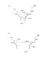
図1は、本実施の形態が適用された画像形成装置1の概略構成を示した図である。この画像形成装置1には、プロセスカートリッジ100が設けられ記録材の一例としての用紙Pに対してトナー像を形成する画像形成部10が設けられている。また、画像形成部10により用紙Pに形成されたトナー像を加熱および加圧し定着する定着部20、および画像形成部10に用紙Pを供給する用紙供給部30が設けられている。
Embodiments of the present invention will be described below in detail with reference to the accompanying drawings.
FIG. 1 is a diagram illustrating a schematic configuration of an image forming apparatus 1 to which the exemplary embodiment is applied. The image forming apparatus 1 includes aprocess cartridge 100 and animage forming unit 10 that forms a toner image on a sheet P as an example of a recording material. Further, afixing unit 20 that heats and pressurizes and fixes a toner image formed on the paper P by theimage forming unit 10 and apaper supply unit 30 that supplies the paper P to theimage forming unit 10 are provided.

ここで、プロセスカートリッジ100は、画像形成装置1のフロント側(図中手前側)に引き抜くことで画像形成装置1の本体部(装置本体)から取り外しできるようになっている。また本実施形態では、プロセスカートリッジ100を取り外すことにより、他のプロセスカートリッジ100を装着可能となっている。ここで、プロセスカートリッジ100には、感光体ドラム11、帯電装置12、現像装置14、およびクリーニング装置16が設けられている。また本実施形態における画像形成装置1には、露光装置13および転写装置15が設けられている。  Here, theprocess cartridge 100 can be removed from the main body (apparatus main body) of the image forming apparatus 1 by being pulled out to the front side (front side in the figure) of the image forming apparatus 1. In the present embodiment, by removing theprocess cartridge 100, anotherprocess cartridge 100 can be mounted. Here, theprocess cartridge 100 is provided with aphotosensitive drum 11, acharging device 12, a developingdevice 14, and acleaning device 16. Further, the image forming apparatus 1 in the present embodiment is provided with anexposure device 13 and atransfer device 15.

また本画像形成装置1には、画像形成装置1の装置本体に対して着脱可能に設けられ、上記プロセスカートリッジ100に供給されるトナーを収容したトナーカートリッジ80(装着部材、装着体の一例)が設けられている。ここでこのトナーカートリッジ80には、EEPROM(Electrically Erasable and Programmable ROM)などにより構成される記憶媒体17が取り付けられている。この記憶媒体17には、トナーカートリッジ80の種類を示す情報や、トナーカートリッジ80の内部に設けられた回転部材(トナーの搬送に用いられる回転部材)の回転数などトナーカートリッジ80の使用状況に関する情報が格納される。  Further, the image forming apparatus 1 includes a toner cartridge 80 (an example of a mounting member and a mounting body) that is detachably attached to the apparatus main body of the image forming apparatus 1 and contains toner supplied to theprocess cartridge 100. Is provided. Here, astorage medium 17 constituted by an EEPROM (Electrically Erasable and Programmable ROM) or the like is attached to thetoner cartridge 80. In thisstorage medium 17, information indicating the type of thetoner cartridge 80, and information regarding the usage status of thetoner cartridge 80 such as the number of rotations of a rotating member (a rotating member used for toner transfer) provided in thetoner cartridge 80. Is stored.

ここで、プロセスカートリッジ100に設けられた感光体ドラム11は、その外周面に感光層を備えており図中矢印方向に回転する。帯電装置12は、感光体ドラム11に接触する帯電ロールを有し感光体ドラム11を予め定められた電位に帯電する。露光装置13は、レーザを感光体ドラム11に照射し帯電装置12により帯電した感光体ドラム11を選択的に露光して感光体ドラム11に静電潜像を形成する。また現像装置14は、現像ロールを有し感光体ドラム11上にトナー像を形成する。  Here, thephotosensitive drum 11 provided in theprocess cartridge 100 has a photosensitive layer on its outer peripheral surface, and rotates in the direction of the arrow in the figure. The chargingdevice 12 has a charging roll in contact with thephotosensitive drum 11 and charges thephotosensitive drum 11 to a predetermined potential. Theexposure device 13 irradiates thephotosensitive drum 11 with laser and selectively exposes thephotosensitive drum 11 charged by the chargingdevice 12 to form an electrostatic latent image on thephotosensitive drum 11. The developingdevice 14 has a developing roll and forms a toner image on thephotosensitive drum 11.

より具体的に説明すると、現像装置14には、例えば、負極性に帯電するトナー及び正極性に帯電するキャリアからなる2成分現像剤が収容されている。そしてこの現像装置14は、感光体ドラム11上に形成された静電潜像をトナーで現像して感光体ドラム11上にトナー像を形成する。転写装置15は、ロール状部材を有し転写装置15と感光体ドラム11との間(転写部Tp)に電界を形成することにより、感光体ドラム11上のトナー像を用紙Pに転写する。またクリーニング装置16は、感光体ドラム11に接触するクリーニングブレードを有しこのクリーニングブレードを用いて感光体ドラム11上に残留するトナー等を除去する。  More specifically, the developingdevice 14 contains, for example, a two-component developer including a negatively charged toner and a positively charged carrier. The developingdevice 14 develops the electrostatic latent image formed on thephotosensitive drum 11 with toner to form a toner image on thephotosensitive drum 11. Thetransfer device 15 has a roll-like member and transfers the toner image on thephotosensitive drum 11 onto the paper P by forming an electric field between thetransfer device 15 and the photosensitive drum 11 (transfer portion Tp). Thecleaning device 16 has a cleaning blade that contacts thephotosensitive drum 11, and removes toner and the like remaining on thephotosensitive drum 11 using the cleaning blade.

一方、用紙供給部30は、図1に示すように、異なるサイズの用紙Pを画像形成部10に対して供給可能なように第1給紙部31〜第3給紙部33を備えている。ここで第1給紙部31〜第3給紙部33は同様に構成されている。第1給紙部31を一例に説明すると、第1給紙部31は、用紙Pを収容する用紙収容部41、引き込みロール43、および捌き機構44を備える。用紙収容部41は、上部に開口を有するとともに直方体状の形状を有しておりその内部に用紙Pを複数枚収容する。引き込みロール43は、用紙収容部41に収容される用紙束のうち最上位の用紙Pに接触しこの最上位の用紙Pを捌き機構44に向けて送り出す。捌き機構44は、例えば回転可能なフィードロールと回転が制限されたリタードロールとによって構成され、引き込みロール43により送り出された用紙Pを一枚ずつに捌く。  On the other hand, as shown in FIG. 1, thepaper supply unit 30 includes a firstpaper supply unit 31 to a third paper supply unit 33 so that paper P of different sizes can be supplied to theimage forming unit 10. . Here, the firstpaper feed unit 31 to the third paper feed unit 33 are similarly configured. The firstpaper feed unit 31 will be described as an example. The firstpaper feed unit 31 includes apaper storage unit 41 that stores paper P, a drawingroll 43, and a windingmechanism 44. Thesheet storage unit 41 has an opening at the top and a rectangular parallelepiped shape, and stores a plurality of sheets P therein. The pull-inroll 43 comes into contact with the uppermost sheet P of the sheet bundle accommodated in thesheet accommodating unit 41 and sends out the uppermost sheet P toward the windingmechanism 44. Thewebbing mechanism 44 is constituted by, for example, a rotatable feed roll and a retard roll with limited rotation, and the paper P fed by the pull-inroll 43 is spread one by one.

また用紙供給部30には、レジストレーションロール(レジロール)852が設けられている。このレジロール852は、回転を停止した状態で用紙Pの搬送を一時的に止め、予め定められたタイミングにて回転を行うことにより、転写部Tpに対してレジストレーション調整を施しながら用紙Pを供給する。また用紙供給部30には、第2給紙部32から搬送されてきた用紙Pをレジロール852に向けて搬送する第1搬送ロール55と、第3給紙部33から搬送されてきた用紙Pを第1搬送ロール55に向けて搬送する第2搬送ロール65が設けられている。  Thepaper supply unit 30 is provided with a registration roll (registration roll) 852. Theregistration roll 852 temporarily stops the conveyance of the sheet P in a state where the rotation is stopped, and rotates the sheet P at a predetermined timing, thereby supplying the sheet P while performing registration adjustment on the transfer portion Tp. To do. In addition, thepaper supply unit 30 receives thefirst conveyance roll 55 that conveys the paper P conveyed from the secondpaper supply unit 32 toward theregistration roll 852 and the paper P conveyed from the third paper supply unit 33. Asecond transport roll 65 that transports toward thefirst transport roll 55 is provided.

また本実施形態における画像形成装置1には、定着部20を通過した用紙Pが積載される用紙積載部YSが設けられている。さらに画像形成装置1には、用紙Pが搬送される用紙搬送経路YRが設けられている。また本実施形態における画像形成装置1では、定着部20を通過した用紙Pの表裏を反転させてこの用紙Pを転写部Tpに再度供給する用紙反転機構40が設けられている。この用紙反転機構40には、定着部20の下流側にて用紙搬送経路YRに接続され且つレジロール852の上流側にて用紙搬送経路YRに合流する反転用搬送経路SRが設けられている。また用紙反転機構40には、反転用搬送経路SR上の用紙Pを搬送する搬送ロール48が設けられている。  Further, the image forming apparatus 1 according to the present exemplary embodiment includes a paper stacking unit YS on which the paper P that has passed through the fixingunit 20 is stacked. Further, the image forming apparatus 1 is provided with a paper transport path YR through which the paper P is transported. Further, in the image forming apparatus 1 according to the present embodiment, apaper reversing mechanism 40 that reverses the front and back of the paper P that has passed through the fixingunit 20 and re-feeds the paper P to the transfer unit Tp is provided. Thesheet reversing mechanism 40 is provided with a reversing transport path SR that is connected to the paper transport path YR on the downstream side of the fixingunit 20 and merges with the paper transport path YR on the upstream side of theregistration roll 852. Thepaper reversing mechanism 40 is provided with atransport roll 48 that transports the paper P on the transport path SR for reversal.

また画像形成装置1には、画像形成装置1の上部に設けられたスキャナ200(画像読み取り装置)や不図示のパーソナルコンピュータ(PC)等からの画像データを受信する受信部400が設けられている。また、画像形成部10、定着部20、および用紙供給部30の動作全般を制御する制御部500、受信部400にて受信された画像データに画像処理を施した後に露光装置13に画像データを出力する画像処理部600が設けられている。  In addition, the image forming apparatus 1 is provided with a receivingunit 400 that receives image data from a scanner 200 (image reading apparatus) or a personal computer (PC) (not shown) provided on the top of the image forming apparatus 1. . Theimage forming unit 10, the fixingunit 20, and thecontrol unit 500 that controls the overall operation of thepaper supply unit 30, and the image data received by the receivingunit 400 are subjected to image processing, and then the image data is sent to theexposure device 13. Animage processing unit 600 for outputting is provided.

さらに画像形成装置1には、表示パネルにより構成されユーザからの指示を受け付けるとともにユーザに対してメッセージ等を表示するユーザインタフェース(UI)700が設けられている。なお、制御部500は、CPU(Central Processing Unit)、ROM(Read Only Memory)、RAM(Random Access Memory)、およびHDD(Hard Disk Drive)(何れも不図示)により構成されている。CPUでは、処理プログラムが実行される。ROMには、各種プログラム、各種テーブル、パラメータ等が記憶されている。RAMは、CPUによる各種プログラムの実行時におけるワークエリア等として用いられる。  Further, the image forming apparatus 1 is provided with a user interface (UI) 700 that is configured by a display panel and receives instructions from the user and displays messages and the like to the user. Thecontrol unit 500 includes a CPU (Central Processing Unit), a ROM (Read Only Memory), a RAM (Random Access Memory), and an HDD (Hard Disk Drive) (all not shown). In the CPU, a processing program is executed. Various programs, various tables, parameters, and the like are stored in the ROM. The RAM is used as a work area when the CPU executes various programs.

ここで用紙Pに画像が形成される際には、図示しないパーソナルコンピュータ等にて形成された画像データが受信部400にて受信され、受信部400から画像処理部600へこの画像データが出力される。そして画像処理部600にて、画像データに対して画像処理が施される。そして画像処理が施された画像データは、露光装置13に出力される。画像データを取得した露光装置13は、帯電装置12により帯電した感光体ドラム11を選択的に露光して静電潜像を形成する。そして、形成された静電潜像は、現像装置14により例えば黒(K)のトナー像として現像される。  Here, when an image is formed on the paper P, image data formed by a personal computer (not shown) or the like is received by the receivingunit 400, and this image data is output from the receivingunit 400 to theimage processing unit 600. The Theimage processing unit 600 performs image processing on the image data. The image data that has been subjected to image processing is output to theexposure device 13. Theexposure device 13 that has acquired the image data selectively exposes thephotosensitive drum 11 charged by the chargingdevice 12 to form an electrostatic latent image. The formed electrostatic latent image is developed by the developingdevice 14 as, for example, a black (K) toner image.

一方、用紙搬送系30では、画像形成のタイミングに合わせて引き込みロール43が回転し、用紙収容部41から用紙Pが供給される。そして、捌き機構44により一枚ずつに捌かれた用紙Pは、レジロール852まで搬送され、一旦、停止される。その後、感光体ドラム11の回転タイミングに合わせてレジロール852が回転し、用紙Pが転写部Tpに供給される。そして、この転写部Tpにおいて感光体ドラム11に形成されたトナー像が用紙Pに転写される。  On the other hand, in thepaper transport system 30, the drawingroll 43 rotates in synchronization with the image formation timing, and the paper P is supplied from thepaper storage unit 41. Then, the sheets P that are rolled up one by one by the rollingmechanism 44 are conveyed to theregistration roll 852 and are temporarily stopped. Thereafter, theregistration roll 852 rotates in accordance with the rotation timing of thephotosensitive drum 11, and the paper P is supplied to the transfer unit Tp. Then, the toner image formed on thephotosensitive drum 11 is transferred onto the paper P in the transfer portion Tp.

その後、トナー像が転写された用紙Pは、定着部20にて定着処理を受け、排出ロール75によってスキャナ200の下部に位置する用紙積載部YSに排出される。なお用紙Pの第1面のみならず第2面にも画像が形成(用紙Pの両面に画像が形成)される際には、定着部20を通過した用紙Pは、用紙反転機構40により表裏が反転されたうえで転写部Tpに再度供給される。そしてこの転写部Tpにて、感光体ドラム11に形成されたトナー像が用紙Pの第2面に転写される。そして、第2面にトナー像が転写された用紙Pは、定着部20によって定着処理を受ける。そしてこの用紙Pは用紙積載部YSに排出される。  Thereafter, the paper P on which the toner image has been transferred undergoes a fixing process in the fixingunit 20 and is discharged by adischarge roll 75 to a paper stacking unit YS located below thescanner 200. When an image is formed not only on the first side of the paper P but also on the second side (images are formed on both sides of the paper P), the paper P that has passed through the fixingunit 20 is turned upside down by thepaper reversing mechanism 40. Is inverted and supplied again to the transfer portion Tp. Then, the toner image formed on thephotosensitive drum 11 is transferred to the second surface of the paper P at the transfer portion Tp. The paper P having the toner image transferred to the second surface is subjected to a fixing process by the fixingunit 20. The paper P is discharged to the paper stacking unit YS.

ここでトナーカートリッジ80について詳細に説明する。
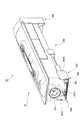
図2は、トナーカートリッジ80の一方側(ユーザにより操作される側とは反対側、画像形成装置1に挿入される際に先頭となる先頭部側)からトナーカートリッジ80を眺めた場合の図である。付言すると、画像形成装置1のリア側から眺めた際のトナーカートリッジ80の状態を示した図である。また図3は、トナーカートリッジ80の側面を示した図である。付言すると、図2の矢印III方向からトナーカートリッジ80を眺めた場合の図である。
Here, thetoner cartridge 80 will be described in detail.
FIG. 2 is a view when thetoner cartridge 80 is viewed from one side of the toner cartridge 80 (the side opposite to the side operated by the user, the leading portion side that is the leading end when inserted into the image forming apparatus 1). is there. In other words, it is a diagram showing a state of thetoner cartridge 80 when viewed from the rear side of the image forming apparatus 1. FIG. 3 is a view showing a side surface of thetoner cartridge 80. In other words, thetoner cartridge 80 is viewed from the direction of arrow III in FIG.

図2に示すように、本実施形態のトナーカートリッジ80は、内部にトナーを収容し画像形成装置1に挿入される筒状部材300を有している。またトナーカートリッジ80には、筒状部材300の長手方向における一端部に取り付けられユーザにより操作される操作部材360が設けられている。ここで筒状部材300には、操作部材360が取り付けられている一端部側とは反対の他端部側に、回転部材301が設けられている。ここでこの回転部材301は、画像形成装置1側から駆動力を受ける受け部として捉えることができる。また筒状部材300および操作部材360により構成された箇所は、トナーカートリッジ80の本体部として捉えることができる。さらに本実施形態では、この回転部材301に接続して設けられるとともに筒状部材300の内部に収容され、回転部材301から駆動力を受けることで回転し、トナーカートリッジ80の内部のトナーを搬送する搬送部材(駆動部の一例、不図示)が設けられている。ここで本実施形態では、トナーカートリッジ80が画像形成装置1に挿入された際に、回転部材301が、画像形成装置1に設けられている回転部材(後述)に連結される。これにより、回転部材301が回転し上記搬送部材が回転する。  As illustrated in FIG. 2, thetoner cartridge 80 according to the present exemplary embodiment includes acylindrical member 300 that contains toner therein and is inserted into the image forming apparatus 1. Further, thetoner cartridge 80 is provided with anoperation member 360 that is attached to one end of thecylindrical member 300 in the longitudinal direction and is operated by a user. Here, thecylindrical member 300 is provided with a rotatingmember 301 on the other end side opposite to the one end side to which theoperation member 360 is attached. Here, the rotatingmember 301 can be regarded as a receiving portion that receives a driving force from the image forming apparatus 1 side. Further, the portion constituted by thecylindrical member 300 and theoperation member 360 can be regarded as a main body portion of thetoner cartridge 80. Further, in the present embodiment, the rotatingmember 301 is provided and connected to the inside of thecylindrical member 300, is rotated by receiving a driving force from the rotatingmember 301, and conveys the toner inside thetoner cartridge 80. A conveying member (an example of a driving unit, not shown) is provided. Here, in this embodiment, when thetoner cartridge 80 is inserted into the image forming apparatus 1, the rotatingmember 301 is coupled to a rotating member (described later) provided in the image forming apparatus 1. Thereby, therotation member 301 rotates and the said conveyance member rotates.

また本実施形態のトナーカートリッジ80では、筒状部材300の先端部且つ下部(下面)に、トナーの排出に用いられる排出口(後述)が形成されている。さらに筒状部材300には、図2に示すように、筒状部材300の長手方向(軸方向)に沿って移動可能に設けられ上記排出口を閉鎖する第1シャッタ302が設けられている。また図2および図3に示すように、筒状部材300の長手方向に沿って移動可能に設けられ、第1シャッタ302を覆う第2シャッタ303が設けられている。また図3に示すように、一端部が第2シャッタ303に取り付けられ他端部が案内部304(後述)に取り付けられ、第2シャッタ303がトナーカートリッジ80の先端部側に移動するように第2シャッタ303を引っ張るコイルスプリングSPが設けられている。  Further, in thetoner cartridge 80 of the present embodiment, a discharge port (described later) used for discharging the toner is formed at the distal end portion and the lower portion (lower surface) of thecylindrical member 300. Furthermore, as shown in FIG. 2, thecylindrical member 300 is provided with afirst shutter 302 that is provided so as to be movable along the longitudinal direction (axial direction) of thecylindrical member 300 and closes the discharge port. As shown in FIGS. 2 and 3, asecond shutter 303 is provided so as to be movable along the longitudinal direction of thecylindrical member 300 and covers thefirst shutter 302. As shown in FIG. 3, one end is attached to thesecond shutter 303, the other end is attached to a guide portion 304 (described later), and thesecond shutter 303 is moved to the front end side of thetoner cartridge 80. 2 A coil spring SP for pulling theshutter 303 is provided.

一方で、操作部材360は、筒状に形成され、図3に示すように、筒状部材300の一端部側に被せられた状態で筒状部材300に装着されている。ここで本実施形態では、この操作部材360の外周面に対し、上記にて説明した記憶媒体17が装着されている。ここでこの記憶媒体17は、同図に示すように4つの端子17A(接点の一例)を有している。  On the other hand, theoperation member 360 is formed in a cylindrical shape, and is attached to thecylindrical member 300 in a state where it is covered on one end side of thecylindrical member 300 as shown in FIG. Here, in the present embodiment, thestorage medium 17 described above is attached to the outer peripheral surface of theoperation member 360. Here, thestorage medium 17 has fourterminals 17A (an example of contacts) as shown in FIG.

図4は、第2シャッタ303がトナーカートリッジ80の後端部側に移動した後のトナーカートリッジ80の状態を示した図である。上記にて説明した通り、本実施形態では、筒状部材300の長手方向に沿って移動可能に設けられ、第1シャッタ302を覆う第2シャッタ303が設けられている。第2シャッタ303がコイルスプリングSPによる引っ張り力に抗して筒状部材300の長手方向に沿って移動した場合、図4に示すように、第2シャッタ303に覆われていた第1シャッタ302が露出するようになる。なお上記では説明を省略したが、図4に示すように、筒状部材300の両側面(図4では一方の側面のみを図示)には、筒状部材300の長手方向に沿って設けられ、第2シャッタ303を案内する案内部304が設けられている。  FIG. 4 is a diagram illustrating the state of thetoner cartridge 80 after thesecond shutter 303 has moved to the rear end side of thetoner cartridge 80. As described above, in the present embodiment, thesecond shutter 303 that is provided so as to be movable along the longitudinal direction of thecylindrical member 300 and covers thefirst shutter 302 is provided. When thesecond shutter 303 moves along the longitudinal direction of thecylindrical member 300 against the pulling force of the coil spring SP, thefirst shutter 302 covered by thesecond shutter 303 is moved as shown in FIG. Be exposed. Although not described above, as shown in FIG. 4, both side surfaces of the cylindrical member 300 (only one side surface is shown in FIG. 4) are provided along the longitudinal direction of thecylindrical member 300. Aguide unit 304 that guides thesecond shutter 303 is provided.

図5は、第1シャッタ302および第2シャッタ303がトナーカートリッジ80の後端部側に移動した後のトナーカートリッジ80の状態を示した図である。上記にて説明したとおり、筒状部材300の先端部且つ下部には、トナーカートリッジ80の内部に収容されたトナーの排出に用いられる排出口305が形成されている。そして本実施形態では、第1シャッタ302がこの排出口305を覆うとともに、第1シャッタ302が筒状部材300の長手方向に沿って移動することで排出口305が露出するようになっている。そしてこのように排出口305が露出することで、トナーカートリッジ80の内部のトナーが排出可能となっている。なお、排出口305の周囲には、トナーの漏れ出しを抑制するためにシール部材として機能する弾性部材306が設けられている。  FIG. 5 is a diagram illustrating the state of thetoner cartridge 80 after thefirst shutter 302 and thesecond shutter 303 have moved to the rear end side of thetoner cartridge 80. As described above, thedischarge port 305 used to discharge the toner stored in thetoner cartridge 80 is formed at the tip and bottom of thecylindrical member 300. In the present embodiment, thefirst shutter 302 covers thedischarge port 305, and thedischarge port 305 is exposed when thefirst shutter 302 moves along the longitudinal direction of thecylindrical member 300. Thus, by exposing thedischarge port 305, the toner inside thetoner cartridge 80 can be discharged. Anelastic member 306 that functions as a seal member is provided around thedischarge port 305 in order to suppress toner leakage.

なお上記では説明を省略したが、第2シャッタ303は、筒状部材300の底部と対向する対向片3031と、側片3032とから構成されている。より具体的には、平板状に形成された対向片3031と、同じく平板状に形成された側片3032とから構成されている。ここで、側片3032は、2つ設けられており、一方の側片303Bは、対向片3031の一方の端部に接続して設けられるとともに対向片3031との接続部からトナーカートリッジ80の上部側に向かうように設けられている。また他方の側片303Cは、対向片3031の他方の端部に接続して設けられるとともに、上記と同様、対向片3031との接続部からトナーカートリッジ80の上部側に向かうように設けられている。  Although not described above, thesecond shutter 303 includes a facingpiece 3031 that faces the bottom of thecylindrical member 300 and aside piece 3032. More specifically, it is composed of a facingpiece 3031 formed in a flat plate shape and aside piece 3032 formed in a flat plate shape. Here, twoside pieces 3032 are provided, and oneside piece 303B is provided so as to be connected to one end portion of the opposingpiece 3031 and from the connecting portion with the opposingpiece 3031 to the upper part of thetoner cartridge 80. It is provided to go to the side. Theother side piece 303C is provided so as to be connected to the other end portion of the opposingpiece 3031 and is provided so as to face the upper side of thetoner cartridge 80 from the connecting portion with the opposingpiece 3031 as described above. .

また本実施形態におけるトナーカートリッジ80では、排出口305よりもトナーカートリッジ80の後端部側に、後述する変位突起954(図15参照)を押圧する押圧突起307が設けられている。なお本実施形態におけるトナーカートリッジ80では、第2シャッタ303により第1シャッタ302が覆われている際、この押圧突起307も第2シャッタ303により覆われるようになっている。このような構成の場合、押圧突起307の破損が生じにくくなる。なお図5では、図中の右側に向かって突出する一つの押圧突起307のみが示されているが、図中の左側に向かって突出する押圧突起307も設けられている(不図示)。  Further, in thetoner cartridge 80 in the present embodiment, apressing protrusion 307 that presses a displacement protrusion 954 (see FIG. 15) described later is provided on the rear end side of thetoner cartridge 80 from thedischarge port 305. In thetoner cartridge 80 according to this embodiment, when thefirst shutter 302 is covered by thesecond shutter 303, thepressing protrusion 307 is also covered by thesecond shutter 303. In the case of such a configuration, thepressing protrusion 307 is hardly damaged. In FIG. 5, only one pressingprotrusion 307 protruding toward the right side in the drawing is shown, but apressing protrusion 307 protruding toward the left side in the drawing is also provided (not shown).

図6は、図5のVI−VI線におけるトナーカートリッジ80の断面図である。
同図に示すようにトナーカートリッジ80の筒状部材300には、筒状部材300の外表面から筒状部材300の径方向に向かって突出する第1突出部371と第2突出部372とが設けられている。なお上記排出口305は、この第1突出部371と第2突出部372との間に形成されている。また本実施形態では、第1突出部371の上端部に接続され、第2突出部372から離れる方向に向かって突出するとともに、筒状部材300の外表面に対向して配置される第1対向片373が設けられている。さらに、第2突出部372の上端部に接続され、第1突出部371から離れる方向に向かって突出するとともに、筒状部材300の外表面に対向して配置される第2対向片374が設けられている。
6 is a cross-sectional view of thetoner cartridge 80 taken along line VI-VI in FIG.
As shown in the figure, thecylindrical member 300 of thetoner cartridge 80 includes a first protrudingportion 371 and a second protrudingportion 372 that protrude from the outer surface of thecylindrical member 300 toward the radial direction of thecylindrical member 300. Is provided. Thedischarge port 305 is formed between the first projectingportion 371 and the second projectingportion 372. In the present embodiment, the first opposing portion is connected to the upper end portion of the first protrudingportion 371 and protrudes in a direction away from the second protrudingportion 372 and is disposed to face the outer surface of thecylindrical member 300. Apiece 373 is provided. Furthermore, a second opposingpiece 374 is provided that is connected to the upper end of the second projectingportion 372 and projects in a direction away from the first projectingportion 371 and is disposed to face the outer surface of thecylindrical member 300. It has been.

一方で、第1シャッタ302にも、板状に形成されたシャッタ本体部302Aの一端部側に接続されこのシャッタ本体部302Aに対向する第1対向片302Bと、シャッタ本体部302Aの他端部側に接続されシャッタ本体部302Aに対向する第2対向片302Cとが設けられている。ここで本実施形態では、筒状部材300の外表面と第1対向片373との間に形成された間隙に、第1シャッタ302の第1対向片302Bが位置している。また、筒状部材300の外表面と第2対向片374との間に形成された間隙に、第1シャッタ302の第2対向片302Cが位置している。これより第1シャッタ302の脱落が防止されるとともにトナーカートリッジ80の長手方向における第1シャッタ302の移動が可能になっている。  On the other hand, thefirst shutter 302 is also connected to one end of the shuttermain body 302A formed in a plate shape and is opposed to the shuttermain body 302A, and the other end of the shuttermain body 302A. And asecond facing piece 302C facing the shuttermain body 302A. Here, in the present embodiment, the first facingpiece 302B of thefirst shutter 302 is located in the gap formed between the outer surface of thecylindrical member 300 and the first facingpiece 373. Further, the second opposingpiece 302C of thefirst shutter 302 is located in a gap formed between the outer surface of thecylindrical member 300 and the second opposingpiece 374. This prevents thefirst shutter 302 from falling off and allows thefirst shutter 302 to move in the longitudinal direction of thetoner cartridge 80.

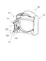
次に操作部材360について詳細に説明する。
図7は、筒状部材300が設けられている側から操作部材360を眺めた場合の図である。同図に示すように、操作部材360は、筒状に形成され、外周面に上記記憶媒体17が装着されている。また操作部材360には、操作部材360の本体部から突出するように設けられ、トナーカートリッジ80が画像形成装置1に装着される際に画像形成装置1の本体側に設けられた挿入口(後述)に挿入される2つの挿入部361(突出部、抑制部の一例)が設けられている。ここで本実施形態では、トナーカートリッジ80が画像形成装置1に装着される際に画像形成装置1の挿入口(後述)にこの挿入部361が入り込む。これにより、トナーカートリッジ80の移動が規制されトナーカートリッジ80の位置決めが行われる。そしてこれにより本実施形態では、記憶媒体17の端子17A(図3参照)と画像形成装置1側に設けられた端子(後述)との接触が維持されやすくなっている。
Next, theoperation member 360 will be described in detail.
FIG. 7 is a view when theoperation member 360 is viewed from the side where thecylindrical member 300 is provided. As shown in the figure, theoperation member 360 is formed in a cylindrical shape, and thestorage medium 17 is mounted on the outer peripheral surface. Theoperation member 360 is provided so as to protrude from the main body of theoperation member 360, and an insertion port (described later) provided on the main body side of the image forming apparatus 1 when thetoner cartridge 80 is mounted on the image forming apparatus 1. ) Are inserted in two insertion portions 361 (an example of a protruding portion and a suppressing portion). Here, in this embodiment, when thetoner cartridge 80 is mounted on the image forming apparatus 1, theinsertion portion 361 enters an insertion port (described later) of the image forming apparatus 1. Thereby, the movement of thetoner cartridge 80 is restricted, and the positioning of thetoner cartridge 80 is performed. As a result, in this embodiment, the contact between the terminal 17A (see FIG. 3) of thestorage medium 17 and a terminal (described later) provided on the image forming apparatus 1 side is easily maintained.

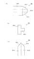
図8は、挿入部361を説明するための図である。詳細には、同図(A)は図7の矢印VIIIA方向から眺めた場合の挿入部361を示し、同図(B)は図7の矢印VIIIB方向から眺めた場合の挿入部361を示し、同図(C)は図7の矢印VIIIC方向から眺めた場合の挿入部361を示している。  FIG. 8 is a diagram for explaining theinsertion portion 361. Specifically, FIG. 7A shows theinsertion portion 361 when viewed from the direction of arrow VIIIA in FIG. 7, and FIG. 7B shows theinsertion portion 361 when viewed from the direction of arrow VIIIB of FIG. FIG. 8C shows theinsertion portion 361 when viewed from the direction of arrow VIIIC in FIG.

挿入部361は、同図(B)に示すように、筒状部材300が設けられている側から眺めた場合の断面形状がT字状となっている。付言すると、トナーカートリッジ80の挿入方向における下流側から眺めた場合の断面形状がT字状となっている。このようにT字状に形成されている場合、挿入部361が単に平板状に形成される場合に比べ、挿入部361の剛性が高まる。  Theinsertion portion 361 has a T-shaped cross section when viewed from the side where thetubular member 300 is provided, as shown in FIG. In addition, the cross-sectional shape when viewed from the downstream side in the insertion direction of thetoner cartridge 80 is a T-shape. Thus, when formed in T shape, the rigidity of theinsertion part 361 increases compared with the case where theinsertion part 361 is simply formed in flat form.

挿入部361についてさらに具体的に説明すると、挿入部361は、トナーカートリッジ80の長手方向に沿うように設けられた平板状の基部361Aを有している。また挿入部361は、基部361Aから突出した状態で設けられるとともに基部361Aと直交する関係で配置され、且つ、トナーカートリッジ80の長手方向に沿うように設けられた突出部361Bを有している。さらに挿入部361の先端には面とりが施されており、同図(A)に示すように、基部361Aの先端に位置する2つの角部(基部361Aの幅方向における両端に位置する2つの角部)には傾斜面361Cが形成されている。また、同図(C)に示すように、突出部361Bの先端に位置する1つの角部にも傾斜面361Dが形成されている。また同図(C)に示すように、基部361Aの厚み方向における一端部に位置する角部にも面とりが施されており、この部位にも傾斜面361Eが形成されている。  Theinsertion portion 361 will be described in more detail. Theinsertion portion 361 has a flat plate-like base portion 361 A provided along the longitudinal direction of thetoner cartridge 80. Theinsertion portion 361 has aprotrusion 361B that is provided in a state of protruding from thebase 361A, is disposed in a relationship orthogonal to thebase 361A, and is provided along the longitudinal direction of thetoner cartridge 80. Further, the distal end of theinsertion portion 361 is chamfered, and as shown in FIG. 3A, two corner portions (two ends located at both ends in the width direction of thebase portion 361A) are located at the distal end of thebase portion 361A. Aninclined surface 361C is formed at the corner. Further, as shown in FIG. 5C, aninclined surface 361D is also formed at one corner located at the tip of the protrudingportion 361B. Further, as shown in FIG. 5C, the corner portion located at one end in the thickness direction of thebase portion 361A is also chamfered, and aninclined surface 361E is also formed at this portion.

次に、画像形成装置1のうちのトナーカートリッジ80が装着される箇所について説明する。ここで図9は、画像形成装置1のうちトナーカートリッジ80が装着される箇所を示した斜視図である。また図10は、トナーカートリッジ80を収容する収容部材900の正面図である。  Next, a location where thetoner cartridge 80 of the image forming apparatus 1 is mounted will be described. Here, FIG. 9 is a perspective view showing a portion of the image forming apparatus 1 where thetoner cartridge 80 is mounted. FIG. 10 is a front view of ahousing member 900 that houses thetoner cartridge 80.

図9に示すように、画像形成装置1のうちトナーカートリッジ80が装着される箇所には、樋状に形成されトナーカートリッジ80を収容する収容部材900が設けられている。さらに本実施形態では、この収容部材900のうちのトナーカートリッジ80の挿入が開始される入口部側に、記憶媒体17に形成された端子17A(図3参照)に接触する端子911(図14参照)を保持した保持部材910(本体側部材の一例)が設けられている。ここで保持部材910には、図10に示すように、上述した挿入部361が挿入される挿入口921(凹部の一例)が形成されるとともに板状且つ矩形状に形成され挿入部361の位置決めを行う位置決め部920が設けられている。なお図10、図11では、端子911(図14参照)の図示を省略している。また本実施形態における位置決め部920は、トナーカートリッジ80の挿入方向と交差する方向へのトナーカートリッジ80の移動を規制する規制部として捉えることができる。  As shown in FIG. 9, astorage member 900 that is formed in a bowl shape and stores thetoner cartridge 80 is provided at a position where thetoner cartridge 80 is mounted in the image forming apparatus 1. Further, in the present embodiment, a terminal 911 (see FIG. 14) that contacts aterminal 17A (see FIG. 3) formed on thestorage medium 17 on the inlet side of thehousing member 900 where the insertion of thetoner cartridge 80 is started. ) (An example of a main body side member) is provided. Here, as shown in FIG. 10, the holdingmember 910 is formed with an insertion port 921 (an example of a concave portion) into which theinsertion portion 361 described above is inserted, and is formed in a plate shape and a rectangular shape, and the positioning of theinsertion portion 361 is performed. Apositioning part 920 for performing the above is provided. 10 and 11, the terminal 911 (see FIG. 14) is not shown. Further, thepositioning portion 920 in the present embodiment can be regarded as a restricting portion that restricts the movement of thetoner cartridge 80 in the direction intersecting the insertion direction of thetoner cartridge 80.

ここで位置決め部920に形成された挿入口921は、図11(保持部材の拡大図)に示すように、2つの挿入部361に対応して2つ設けられている。ここで挿入口921の各々は、同図に示すように正面視にてT字状に形成され、挿入部361の断面形状に倣う形状を有している。より具体的に説明すると、挿入口921には、断面形状が矩形の第1貫通孔921A、同じく矩形状に形成され第1貫通孔921Aに接続して設けられるとともにこの第1貫通孔921Aと直交する関係で配置された第2貫通孔921Bが設けられている。そして本実施形態では、トナーカートリッジ80の挿入がなされる際、第1貫通孔921Aを上記基部361A(図8参照)が通過し、第2貫通孔921Bを上記突出部361Bが通過する。  Here, twoinsertion openings 921 formed in thepositioning portion 920 are provided corresponding to the twoinsertion portions 361 as shown in FIG. 11 (enlarged view of the holding member). Here, each of theinsertion ports 921 is formed in a T shape in a front view as shown in the figure, and has a shape that follows the cross-sectional shape of theinsertion portion 361. More specifically, theinsertion port 921 is provided with a first throughhole 921A having a rectangular cross-sectional shape, which is also formed in a rectangular shape and connected to the first throughhole 921A, and orthogonal to the first throughhole 921A. The 2nd through-hole 921B arrange | positioned by the relationship which concerns is provided. In the present embodiment, when thetoner cartridge 80 is inserted, thebase 361A (see FIG. 8) passes through the first throughhole 921A, and theprotrusion 361B passes through the second throughhole 921B.

図12は、挿入口921を説明するための図である。詳細には、同図(A)は図11のXIIA−XIIA線における断面を示し、同図(B)は図11のXIIB−XIIB線における断面を示している。  FIG. 12 is a diagram for explaining theinsertion slot 921. Specifically, FIG. 11A shows a cross section taken along line XIIA-XIIA in FIG. 11, and FIG. 11B shows a cross section taken along line XIIB-XIIB in FIG.

ここで本実施形態では、挿入口921のうち挿入部361の挿入が開始される入口部側に面とりが施されている。より具体的に説明すると、同図(A)、(B)に示すように、第1貫通孔921Aの内壁面921Cと位置決め部920の外表面920Aとが交差する箇所に対して面取りが施されており、この交差する箇所には傾斜面921Dが形成されている。より具体的には、挿入部361の挿入方向における下流側に進むに従い第1貫通孔921Aの中心部側に接近する傾斜面921Dが形成されている。この傾斜面921Dが形成されていることで、本実施形態では、挿入口921に対し挿入部361が入り込みやすくなっている。なお、挿入部361の先端部にも、上記の通り面取りが形成されているため、挿入口921に対し挿入部361が更に入り込みやすくなっている。  Here, in the present embodiment, chamfering is performed on the inlet portion side of theinsertion port 921 where insertion of theinsertion portion 361 is started. More specifically, as shown in FIGS. 1A and 1B, chamfering is performed at a location where theinner wall surface 921C of the first throughhole 921A and theouter surface 920A of thepositioning portion 920 intersect. Aninclined surface 921D is formed at the intersection. More specifically, aninclined surface 921D that approaches the central portion side of the first throughhole 921A as it goes downstream in the insertion direction of theinsertion portion 361 is formed. By forming theinclined surface 921D, theinsertion portion 361 can easily enter theinsertion port 921 in this embodiment. Since the chamfer is also formed at the distal end portion of theinsertion portion 361 as described above, theinsertion portion 361 can further enter theinsertion port 921 more easily.

なお上記では説明を省略したが、本実施形態では、記憶媒体17および記憶媒体17に接触する端子911(図14参照)を有した保持部材910を、いずれも、トナーカートリッジ80の挿入方向における下流側(奥側)でなく、挿入方向における上流側(手前側)に設けている。より具体的には、記憶媒体17を、トナーカートリッジ80の後端部側に設け、保持部材910を、収容部材900のうちのトナーカートリッジ80の挿入が開示される入口部側に設けている。  Although not described above, in this embodiment, both thestorage medium 17 and the holdingmember 910 having a terminal 911 (see FIG. 14) that contacts thestorage medium 17 are arranged downstream in the insertion direction of thetoner cartridge 80. It is provided not on the side (back side) but on the upstream side (front side) in the insertion direction. More specifically, thestorage medium 17 is provided on the rear end side of thetoner cartridge 80, and the holdingmember 910 is provided on the inlet side of thehousing member 900 where the insertion of thetoner cartridge 80 is disclosed.

ここでトナーカートリッジ80が画像形成装置1に挿入される際、ユーザの操作の仕方によっては、トナーカートリッジ80の挿入位置が一定とならず、画像形成装置1の奥側にて位置ずれが発生した状態で、トナーカートリッジ80の挿入がなされるおそれがある。付言すると、予め定められた経路に沿って真っすぐにトナーカートリッジ80が挿入されずこの経路から外れた状態でトナーカートリッジ80の挿入なされるおそれがある。このような場合において、トナーカートリッジ80の先端部側に記憶媒体17が設けられ、また、画像形成装置1の奥側に端子911が設けられていると、記憶媒体17と端子911との接触がなされなくなるおそれがある。このため本実施形態では、上記のような位置ずれが発生しにくいトナーカートリッジ80の後端部側に記憶媒体17を設けるとともに、画像形成装置1の手前側(トナーカートリッジ80の挿入が開始される側)に記憶媒体17に接触する端子911を設けるようにしている。  Here, when thetoner cartridge 80 is inserted into the image forming apparatus 1, the insertion position of thetoner cartridge 80 is not constant depending on how the user operates, and a position shift occurs on the back side of the image forming apparatus 1. In this state, thetoner cartridge 80 may be inserted. In other words, thetoner cartridge 80 may not be inserted straight along a predetermined path, and thetoner cartridge 80 may be inserted out of the path. In such a case, if thestorage medium 17 is provided on the front end side of thetoner cartridge 80 and the terminal 911 is provided on the back side of the image forming apparatus 1, the contact between thestorage medium 17 and the terminal 911 is prevented. There is a risk that it will not be done. For this reason, in the present embodiment, thestorage medium 17 is provided on the rear end side of thetoner cartridge 80 in which the above-described positional displacement is unlikely to occur, and the front side of the image forming apparatus 1 (insertion of thetoner cartridge 80 is started). The terminal 911 that contacts thestorage medium 17 is provided on the side).

ところで本実施形態では、トナーカートリッジ80の内部に設けられた回転部材(トナーの搬送に用いられる回転部材)の回転により、振動が発生する。そしてこのように振動が発生すると、トナーカートリッジ80の挿入方向と交差する方向(直交する方向)にトナーカートリッジ80が移動(変位)し、保持部材910に設けられた端子911から記憶媒体17の端子17Aが離れる事態が起こり得る。このため本実施形態では、挿入部361および挿入口921を設けることで、端子911に対する端子17Aの移動を抑制し(上記交差する方向への端子17Aの移動を抑制)、端子911と端子17Aとの接触が維持されるようにしている。なお本実施形態では、トナーカートリッジ80側に突出部(挿入部361)を設け、画像形成装置1の本体側に凹部(挿入口921)を設けたが、トナーカートリッジ80側に凹部を設け、画像形成装置1の本体側に突出部を設けることもできる。  By the way, in the present embodiment, vibration is generated by rotation of a rotating member (a rotating member used for toner conveyance) provided in thetoner cartridge 80. When the vibration occurs in this way, thetoner cartridge 80 moves (displaces) in a direction intersecting (orthogonal to) the direction in which thetoner cartridge 80 is inserted, and the terminal of thestorage medium 17 is changed from the terminal 911 provided on the holdingmember 910. The situation where 17A leaves may occur. For this reason, in this embodiment, by providing theinsertion portion 361 and theinsertion port 921, the movement of the terminal 17A with respect to the terminal 911 is suppressed (the movement of the terminal 17A in the intersecting direction is suppressed), and the terminal 911, theterminal 17A, To maintain contact. In this embodiment, the protruding portion (insertion portion 361) is provided on thetoner cartridge 80 side, and the concave portion (insertion port 921) is provided on the main body side of the image forming apparatus 1, but the concave portion is provided on thetoner cartridge 80 side. A protrusion may be provided on the main body side of the forming apparatus 1.

なお端子911は、図14にも示すように、金属片に対し曲げ加工を施すことにより形成され、トナーカートリッジ80が位置する側に向かって突出するように設けられている。そしてこの端子911は、トナーカートリッジ80の挿入がなされた際に、記憶媒体17の端子17Aにより押圧され弾性変形するとともに、端子17Aを押圧する状態となる。このような構成とした場合、記憶媒体17の端子17Aが端子911から離れる方向に移動したとしても、この端子17Aに追従して端子911が移動するようになり、端子17Aと端子911との接触が維持されやすくなる。  As shown in FIG. 14, the terminal 911 is formed by bending a metal piece, and is provided so as to protrude toward the side where thetoner cartridge 80 is located. When thetoner cartridge 80 is inserted, the terminal 911 is pressed by the terminal 17A of thestorage medium 17 to be elastically deformed and presses the terminal 17A. In such a configuration, even if the terminal 17A of thestorage medium 17 moves away from the terminal 911, the terminal 911 moves following theterminal 17A, and the contact between the terminal 17A and the terminal 911 is reached. Is easily maintained.

また本実施形態では、挿入部361が設けられている部材(操作部材360)に対して記憶媒体17を装着している。付言すると、挿入部361および記憶媒体17が共通の部材(部品)に設けられている。さらに説明すると、挿入部361が操作部材360と一体で形成され、記憶媒体17はこの操作部材360に設けられている。ここで、挿入部361および記憶媒体17の各々を異なる部材(部品)に設けることもできるが、この場合、共通の部材に設ける場合に比べ、記憶媒体17が挿入部361に対して動きやすくなってしまう。そしてこのように動きやすくなると、記憶媒体17の変位が生じやすくなり、保持部材910の端子911に対し記憶媒体17の端子17Aがより動きやすくなってしまう。このため本実施形態では、一つ(共通の)の部材(操作部材360)に対して、挿入部361および記憶媒体17を設けている。  In this embodiment, thestorage medium 17 is attached to the member (operation member 360) provided with theinsertion portion 361. In other words, theinsertion portion 361 and thestorage medium 17 are provided on a common member (component). More specifically, theinsertion portion 361 is formed integrally with theoperation member 360, and thestorage medium 17 is provided on theoperation member 360. Here, each of theinsertion unit 361 and thestorage medium 17 can be provided on different members (parts). However, in this case, thestorage medium 17 can move more easily with respect to theinsertion unit 361 than in the case where theinsertion unit 361 and thestorage medium 17 are provided on a common member. End up. And if it becomes easy to move in this way, the displacement of thestorage medium 17 is likely to occur, and the terminal 17A of thestorage medium 17 becomes easier to move with respect to theterminal 911 of the holdingmember 910. For this reason, in this embodiment, theinsertion portion 361 and thestorage medium 17 are provided for one (common) member (operation member 360).

また本実施形態では、図3に示すように、挿入部361と記憶媒体17とを接近させた状態で、挿入部361および記憶媒体17を配置している。このように、挿入部361と記憶媒体17とを接近させて配置した場合、挿入部361と記憶媒体17とを離して配置した場合に比べ、挿入部361に対する記憶媒体17の変位が生じにくくなる。また本実施形態では、図3に示すように、2つの挿入部361の間に位置する領域3A内に、記憶媒体17が配置されている。このように挿入部361を複数設け、且つ、挿入部361間に記憶媒体17を設ける場合、挿入部361が単数である場合や、挿入部361間に記憶媒体17が位置していない場合に比べ、挿入部361に対する記憶媒体17の変位が生じにくくなる。  In the present embodiment, as shown in FIG. 3, theinsertion unit 361 and thestorage medium 17 are arranged in a state where theinsertion unit 361 and thestorage medium 17 are brought close to each other. Thus, when theinsertion portion 361 and thestorage medium 17 are arranged close to each other, the displacement of thestorage medium 17 with respect to theinsertion portion 361 is less likely to occur than when theinsertion portion 361 and thestorage medium 17 are arranged apart from each other. . In the present embodiment, as shown in FIG. 3, thestorage medium 17 is arranged in the area 3 </ b> A located between the twoinsertion portions 361. As described above, when a plurality of theinsertion portions 361 are provided and thestorage medium 17 is provided between theinsertion portions 361, the case where the number of theinsertion portions 361 is single or thestorage medium 17 is not located between theinsertion portions 361 is compared. The displacement of thestorage medium 17 with respect to theinsertion portion 361 is less likely to occur.

また図7に示すように、挿入部361および記憶媒体17は、操作部材360(トナーカートリッジ80)のうちの一方の側面側(一側面側)に設けられている。付言すると、挿入部361および記憶媒体17の両者は、操作部材360に設けられている複数の面のうちの同じ面に対して設けられている。ここで例えば、挿入部361を図7における第1側面368側に設け、記憶媒体17を図7における第2側面369(第1側面368とは反対側に位置する側面)側に設けこともできるが、この場合、一方の側面側に挿入部361および記憶媒体17の両者が設けられている場合に比べ、挿入部361に対する記憶媒体17の変位が生じやすくなる。このため本実施形態では、操作部材360のうちの一方の側面側(同じ側面側)に挿入部361および記憶媒体17を設けている。  As shown in FIG. 7, theinsertion portion 361 and thestorage medium 17 are provided on one side surface (one side surface) of the operation member 360 (toner cartridge 80). In addition, both theinsertion portion 361 and thestorage medium 17 are provided on the same surface among the plurality of surfaces provided on theoperation member 360. Here, for example, theinsertion portion 361 can be provided on thefirst side surface 368 side in FIG. 7 and thestorage medium 17 can be provided on the second side surface 369 (side surface opposite to the first side surface 368) side in FIG. However, in this case, the displacement of thestorage medium 17 with respect to theinsertion portion 361 is more likely to occur than when both theinsertion portion 361 and thestorage medium 17 are provided on one side surface side. Therefore, in the present embodiment, theinsertion portion 361 and thestorage medium 17 are provided on one side surface (the same side surface) of theoperation member 360.

またトナーカートリッジ80の長手方向における一端部側に記憶媒体17を設けトナーカートリッジ80の長手方向における他端部側に挿入部361を設けることもできるが、この場合、記憶媒体17と挿入部361との距離が大きくなる。そしてこのような場合、上記と同様、挿入部361に対する記憶媒体17の変位が生じやすくなる。このため本実施形態では、2つの端部のうちの同じ端部側に、記憶媒体17および挿入部361を設ける構成としている。付言すると、本実施形態では、記憶媒体17はトナーカートリッジ80の長手方向における一方の端部側に設けられ、保持部材910の位置決め部920がトナーカートリッジ80に接触する箇所も、トナーカートリッジ80の長手方向における一方の端部側となっている。  Further, thestorage medium 17 can be provided on one end side in the longitudinal direction of thetoner cartridge 80 and theinsertion portion 361 can be provided on the other end side in the longitudinal direction of thetoner cartridge 80. In this case, thestorage medium 17 and theinsertion portion 361 The distance becomes larger. In such a case, similarly to the above, the displacement of thestorage medium 17 with respect to theinsertion portion 361 is likely to occur. Therefore, in the present embodiment, thestorage medium 17 and theinsertion portion 361 are provided on the same end side of the two end portions. In addition, in the present embodiment, thestorage medium 17 is provided on one end side in the longitudinal direction of thetoner cartridge 80, and the position where thepositioning portion 920 of the holdingmember 910 contacts thetoner cartridge 80 is also the longitudinal direction of thetoner cartridge 80. One end side in the direction.

さらに本実施形態では、記憶媒体17および挿入部361を、トナーカートリッジ80のうちの回転部材301(図2参照)が設けられている側とは反対側に設けている。本トナーカートリッジ80では、回転部材301が設けられている側(駆動力を受ける側)にて振動が大きくなる傾向にある。このため本実施形態では、トナーカートリッジ80のうちの回転部材301が設けられている側とは反対側に、記憶媒体17および挿入部361を設けるようにしている。なお上記では、挿入部361の断面形状をT字状としたが、T字状に限らず、矩形、三角形、楕円、円などの形状とすることもできる。また上記では、トナーカートリッジ80に記憶媒体17が設けられている場合を説明したが、これは一例であり、記憶媒体17はプロセスカートリッジ100などに設けられる場合もある。付言すると、上記にて示した構成は、プロセスカートリッジ100などの他の着脱体に対しても適用可能である。  Furthermore, in this embodiment, thestorage medium 17 and theinsertion portion 361 are provided on the opposite side of thetoner cartridge 80 from the side on which the rotation member 301 (see FIG. 2) is provided. In thetoner cartridge 80, the vibration tends to increase on the side where the rotatingmember 301 is provided (the side receiving the driving force). Therefore, in the present embodiment, thestorage medium 17 and theinsertion portion 361 are provided on the opposite side of thetoner cartridge 80 from the side on which therotation member 301 is provided. In the above description, the cross-sectional shape of theinsertion portion 361 is a T-shape, but is not limited to a T-shape, and may be a rectangle, a triangle, an ellipse, a circle, or the like. In the above description, thestorage medium 17 is provided in thetoner cartridge 80. However, this is an example, and thestorage medium 17 may be provided in theprocess cartridge 100 or the like. In addition, the configuration described above can be applied to other detachable bodies such as theprocess cartridge 100.

また、挿入部361に、位置決め部920に対する挿入部361の移動を規制する規制部を設けることもできる。付言すると、挿入口921から挿入部361が抜ける方向への挿入部361の移動を規制する規制部を挿入部361に対して設けることができる。
図13は、挿入部361に設けられた規制部を説明するための図である。
挿入部361には、同図(A)に示すように、トナーカートリッジ80の長手方向に沿うように設けられた第1基部361Gと、この第1基部361Gとの間に間隙を有した状態で配置され同じくトナーカートリッジ80の長手方向に沿うように設けられた第2基部361Hと、が設けられている。
In addition, theinsertion portion 361 can be provided with a restriction portion that restricts the movement of theinsertion portion 361 relative to thepositioning portion 920. In addition, a restricting portion that restricts the movement of theinsertion portion 361 in the direction in which theinsertion portion 361 is removed from theinsertion port 921 can be provided for theinsertion portion 361.
FIG. 13 is a view for explaining a restricting portion provided in theinsertion portion 361.
As shown in FIG. 6A, theinsertion portion 361 has afirst base portion 361G provided along the longitudinal direction of thetoner cartridge 80 and a gap between thefirst base portion 361G. Asecond base portion 361H that is disposed and is provided along the longitudinal direction of thetoner cartridge 80 is also provided.

また、第1基部361Gに接続して設けられるとともにトナーカートリッジ80の挿入方向における下流側に向かうに従い第2基部361H側から離れる第1片部361J、第2基部361Hに接続して設けられるとともにトナーカートリッジ80の挿入方向における下流側に向かうに従い第1基部361G側から離れる第2片部361Kが設けられている。さらに、第1片部361Jに接続して設けられ、トナーカートリッジ80の挿入方向における下流側に向かうに従い第2基部361Hが設けられている側に接近する第3片部361L、第2片部361Kに接続して設けられ、トナーカートリッジ80の挿入方向における下流側に向かうに従い第1基部361Gが設けられている側に接近する第4片部361Mが設けられている。ここで本実施形態では、第3片部361Lの先端部と第4片部361Mの先端部とが接続されている。  Further, it is provided connected to thefirst base portion 361G and is provided connected to thefirst piece portion 361J and thesecond base portion 361H, which are separated from thesecond base portion 361H side toward the downstream side in the insertion direction of thetoner cartridge 80, and the toner. Asecond piece 361K is provided that moves away from thefirst base 361G side toward the downstream side in the insertion direction of thecartridge 80. Further, thethird piece 361L and thesecond piece 361K are provided connected to thefirst piece 361J and approach the side where thesecond base 361H is provided toward the downstream side in the insertion direction of thetoner cartridge 80. Afourth piece portion 361M is provided that is connected to the first cartridge portion 341M and is closer to the side where thefirst base portion 361G is provided toward the downstream side in the insertion direction of thetoner cartridge 80. Here, in the present embodiment, the tip of thethird piece 361L and the tip of thefourth piece 361M are connected.

ここで本実施形態では、第1片部361Jと第3片部361Lとの接続部に位置する第1頂部361Nと、第2片部361Kと第4片部361Mとの接続部に位置する第2頂部361Pとの離間距離が、挿入口921の幅Lよりも大きくなっている。このため、挿入口921に挿入された挿入部361が引き抜かれる方向に移動する際には、頂部361N,361Pが位置決め部920に突き当たるようになる。これにより、挿入部361が抜ける方向への挿入部361の移動が規制される。  Here, in the present embodiment, the firsttop portion 361N located at the connection portion between thefirst piece portion 361J and thethird piece portion 361L, and the first portion located at the connection portion between thesecond piece portion 361K and thefourth piece portion 361M. The separation distance from the twotop portions 361 </ b> P is larger than the width L of theinsertion port 921. For this reason, when theinsertion part 361 inserted in theinsertion port 921 moves in the direction in which it is pulled out, thetop parts 361N and 361P come into contact with thepositioning part 920. As a result, the movement of theinsertion portion 361 in the direction in which theinsertion portion 361 is removed is restricted.

なお、ユーザによりトナーカートリッジ80が装着される際には、挿入部361が位置決め部920に接触した際に、第1基部361G、第2基部361H、第1片部361J〜第4片部361Mが弾性変形し、第1頂部361Nと第2頂部361Pとが接近する。これにより、挿入口921を挿入部361が通過する。またユーザによりトナーカートリッジ80が取り外される際も、挿入部361が位置決め部920に接触した際に、第1基部361G、第2基部361H、第1片部361J〜第4片部361Mが弾性変形し、第1頂部361Nと第2頂部361Pとが接近する。これにより、挿入口921を挿入部361が通過するようになる。なお上記では、第3片部361Lの先端部と第4片部361Mの先端部とが接続されている場合を例示したが、同図(B)に示すように、第3片部361Lの先端部と第4片部361Mの先端部とを離間させるようにしてもよい。  When the user installs thetoner cartridge 80, thefirst base portion 361G, thesecond base portion 361H, and thefirst piece portion 361J to thefourth piece portion 361M are moved when theinsertion portion 361 comes into contact with thepositioning portion 920. The firsttop portion 361N and the secondtop portion 361P approach each other due to elastic deformation. As a result, theinsertion portion 361 passes through theinsertion port 921. Further, when thetoner cartridge 80 is removed by the user, thefirst base portion 361G, thesecond base portion 361H, and thefirst piece portion 361J to thefourth piece portion 361M are elastically deformed when theinsertion portion 361 contacts thepositioning portion 920. The firsttop portion 361N and the secondtop portion 361P approach each other. As a result, theinsertion portion 361 passes through theinsertion port 921. In addition, although the case where the front-end | tip part of the3rd piece part 361L and the front-end | tip part of the4th piece part 361M were connected was illustrated above, as shown to the same figure (B), the front-end | tip of the3rd piece part 361L is shown. You may make it space | separate a part and the front-end | tip part of the4th piece part 361M.

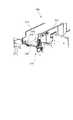
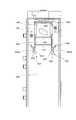
図14は、収容部材900の上方から収容部材900を眺めた場合の斜視図である。また図15は、収容部材900の上面図である。
図14に示すようにまた上記のとおり、収容部材900のうちのトナーカートリッジ80の挿入が開始される入口部側には、保持部材910が設けられている。そしてこの保持部材910には、上記にて説明したとおり、記憶媒体17に形成された端子17A(図3参照)に接触する端子911が設けられている。なお図14では、不図示のモータにより回転駆動し、トナーカートリッジ80に設けられた上記回転部材301(図2参照)を回転させる回転部材990も表示している。
FIG. 14 is a perspective view of thehousing member 900 as viewed from above thehousing member 900. FIG. 15 is a top view of thehousing member 900.
As shown in FIG. 14, as described above, the holdingmember 910 is provided on the inlet side of thehousing member 900 where the insertion of thetoner cartridge 80 is started. As described above, the holdingmember 910 is provided with the terminal 911 that contacts theterminal 17A (see FIG. 3) formed on thestorage medium 17. In FIG. 14, a rotatingmember 990 that is driven to rotate by a motor (not shown) and rotates the rotating member 301 (see FIG. 2) provided in thetoner cartridge 80 is also displayed.

また本実施形態では、図14、図15に示すように、収容部材900の奥側(トナーカートリッジ80の挿入方向における奥側)、且つ、収容部材900の底部に、第1平坦面941が形成されている。さらにこの第1平坦面941に、開口942が形成されている。ここで本実施形態では、この開口942を通じ、トナーカートリッジ80から排出されたトナーが、収容部材900の下方に設けられたトナー搬送機構(不図示)に供給されるようになっている。  In this embodiment, as shown in FIGS. 14 and 15, a firstflat surface 941 is formed on the back side of the housing member 900 (the back side in the insertion direction of the toner cartridge 80) and on the bottom of thehousing member 900. Has been. Further, anopening 942 is formed in the firstflat surface 941. Here, in this embodiment, the toner discharged from thetoner cartridge 80 is supplied to a toner conveyance mechanism (not shown) provided below thestorage member 900 through theopening 942.

また第1平坦面941よりもトナーカートリッジ80の挿入方向における上流側には、この第1平坦面941よりも低い箇所に位置する第2平坦面943が設けられている。また、第2平坦面943よりもトナーカートリッジ80の挿入方向における上流側には、この第2平坦面943よりも低い箇所に位置する第3平坦面944が設けられている。また上下方向に沿って設けられ第1平坦面941と第2平坦面943とを接続する第1接続面945、同じく上下方向に沿って設けられ第2平坦面943と第3平坦面944とを接続する第2接続面946が設けられている。  Further, a secondflat surface 943 located at a position lower than the firstflat surface 941 is provided on the upstream side in the insertion direction of thetoner cartridge 80 from the firstflat surface 941. Further, a thirdflat surface 944 located at a position lower than the secondflat surface 943 is provided upstream of the secondflat surface 943 in the insertion direction of thetoner cartridge 80. Also, afirst connection surface 945 provided along the vertical direction and connecting the firstflat surface 941 and the secondflat surface 943, and a secondflat surface 943 and a thirdflat surface 944 provided along the vertical direction are also provided. Asecond connection surface 946 to be connected is provided.

また収容部材900には、第1平坦面941との間に間隙を有して配置され第1平坦面941と対向する第1対向片947、第2対向片948が設けられている。ここで第1対向片947および第2対向片948は、トナーカートリッジ80の挿入方向(収容部材900の長手方向)に沿うように設けられている。なお上記開口942は、この第1対向片947と第2対向片948との間に配置されている。  Theaccommodating member 900 is provided with a first opposingpiece 947 and a second opposingpiece 948 that are disposed with a gap between theaccommodating member 900 and the firstflat surface 941 and face the firstflat surface 941. Here, the first opposingpiece 947 and the second opposingpiece 948 are provided along the insertion direction of the toner cartridge 80 (the longitudinal direction of the housing member 900). Theopening 942 is disposed between the first facingpiece 947 and thesecond facing piece 948.

さらに本実施形態では、第1接続面945からトナーカートリッジ80の挿入方向における上流側に向かって突出した第1突出片951および第2突出片952が設けられている。ここで第1突出片951および第2突出片952は、弾性変形可能に設けられておりトナーカートリッジ80の挿入方向と直交する方向に撓むことが可能となっている。また、第1突出片951および第2突出片952は、第2接続面946よりもトナーカートリッジ80の挿入方向における上流側に、その先端部が位置するように設けられている。また本実施形態では、第1突出片951と第3平坦面944との間に間隙が形成されている。また第2突出片952と第3平坦面944との間に間隙が形成されている。  Furthermore, in the present embodiment, a firstprotruding piece 951 and a secondprotruding piece 952 that protrude from thefirst connection surface 945 toward the upstream side in the insertion direction of thetoner cartridge 80 are provided. Here, the firstprotruding piece 951 and the secondprotruding piece 952 are provided so as to be elastically deformable, and can be bent in a direction perpendicular to the insertion direction of thetoner cartridge 80. Further, the first projectingpiece 951 and the second projectingpiece 952 are provided such that their tip portions are positioned on the upstream side in the insertion direction of thetoner cartridge 80 from thesecond connection surface 946. In the present embodiment, a gap is formed between the firstprotruding piece 951 and the thirdflat surface 944. Further, a gap is formed between the secondprotruding piece 952 and the thirdflat surface 944.

また第1突出片951および第2突出片952の各々は、図15に示すように、その先端部に、第1シャッタ302(図5参照)の移動経路上に突出し第1シャッタ302の移動(後退)を規制(後述)する規制突起953を備えている。また、第1突出片951および第2突出片952の各々には、トナーカートリッジ80に設けられた押圧突起307(図5参照)により押圧されることで移動し、第1突出片951および第2突出片952を変位させる変位突起954が設けられている。  Further, as shown in FIG. 15, each of the first projectingpiece 951 and the second projectingpiece 952 protrudes on the moving path of the first shutter 302 (see FIG. 5) at the tip thereof, and moves the first shutter 302 ( Arestriction protrusion 953 is provided for restricting (described later) retreat. Further, each of the first projectingpiece 951 and the second projectingpiece 952 is moved by being pressed by a pressing projection 307 (see FIG. 5) provided in thetoner cartridge 80, and the first projectingpiece 951 and the second projectingpiece 951 are moved.Displacement protrusions 954 for displacing the protrudingpieces 952 are provided.

ここで上記変位突起954は、トナーカートリッジ80の挿入方向における上流側に向かうに従い収容部材900の中央部側に接近する傾斜面954Aを有しており、この傾斜面954Aが上記押圧突起307により押圧されることで移動し、第1突出片951および第2突出片952を変位させる。より具体的には、第1突出片951および第2突出片952が互いに離れるように第1突出片951および第2突出片952を変位させる。  Here, thedisplacement protrusion 954 has aninclined surface 954A that approaches the central side of thehousing member 900 as it goes upstream in the insertion direction of thetoner cartridge 80, and theinclined surface 954A is pressed by thepressing protrusion 307. As a result, the first projectingpiece 951 and the second projectingpiece 952 are displaced. More specifically, the first projectingpiece 951 and the second projectingpiece 952 are displaced so that the first projectingpiece 951 and the second projectingpiece 952 are separated from each other.

次に、収容部材900にトナーカートリッジ80が挿入される際の各部の動きを図14を参照しながら説明する。収容部材900へトナーカートリッジ80の挿入が開始されると、トナーカートリッジ80の移動に伴い、第2シャッタ303が収容部材900の奥側に向かって移動していく。そしてこの第2シャッタ303は、第1突出片951と第3平坦面944との間に形成された間隙、および、第2突出片952と第3平坦面944との間に形成された間隙に進入するとともに、第2接続面946に突き当たる。  Next, the movement of each part when thetoner cartridge 80 is inserted into thehousing member 900 will be described with reference to FIG. When the insertion of thetoner cartridge 80 into thehousing member 900 is started, thesecond shutter 303 moves toward the back side of thehousing member 900 as thetoner cartridge 80 moves. Thesecond shutter 303 has a gap formed between the firstprotruding piece 951 and the thirdflat surface 944 and a gap formed between the secondprotruding piece 952 and the thirdflat surface 944. While entering, it hits thesecond connection surface 946.

これにより、第2シャッタ303は、移動が規制され第3平坦面944の上に留まるようになる。なお第2シャッタ303が第2接続面946に突き当たった後、伸長するコイルスプリングSP(図4参照)からトナーカートリッジ80の筒状部材300に対し荷重が作用するようになる。このため、第2シャッタ303が第2接続面946に突き当たった後、ユーザは、この荷重よりも大きい荷重でトナーカートリッジ80を画像形成装置1の奥側に向けて押し込むこととなる。なお本実施形態では、コイルスプリングSPのばね定数が小さく設定されており、コイルスプリングSPからトナーカートリッジ80の筒状部材300に対して作用する荷重は小さくなっている。このため本実施形態では、コイルスプリングSPからの荷重をユーザがほとんど感じないようになっている。付言するとユーザが感じる操作感に変化が生じないようになっている。  As a result, the movement of thesecond shutter 303 is restricted and thesecond shutter 303 remains on the thirdflat surface 944. After thesecond shutter 303 hits thesecond connection surface 946, a load is applied to thecylindrical member 300 of thetoner cartridge 80 from the extending coil spring SP (see FIG. 4). Therefore, after thesecond shutter 303 hits thesecond connection surface 946, the user pushes thetoner cartridge 80 toward the back side of the image forming apparatus 1 with a load larger than this load. In this embodiment, the spring constant of the coil spring SP is set small, and the load acting on thecylindrical member 300 of thetoner cartridge 80 from the coil spring SP is small. For this reason, in this embodiment, the user hardly feels the load from the coil spring SP. In other words, the operation feeling felt by the user is not changed.

その後、トナーカートリッジ80の更なる移動に伴い第1シャッタ302が収容部材900の奥側に向かって移動していく。そして、第1シャッタ302が、第1突出片951と第2突出片952との間に入り込むとともに、第1シャッタ302が第1接続面945に突き当たるようになる。これにより、第1シャッタ302は、その移動が規制され、第2平坦面943上に、且つ、第1突出片951と第2突出片952との間に留まるようになる。その後、本実施形態では、トナーカートリッジ80の更なる移動によって、排出口305が移動し、排出口305が開口942上に位置するようになる。これにより、トナーカートリッジ80の内部のトナーが画像形成装置1の本体側に供給される状態となる。  Thereafter, as thetoner cartridge 80 is further moved, thefirst shutter 302 moves toward the back side of thehousing member 900. Then, thefirst shutter 302 enters between the firstprotruding piece 951 and the secondprotruding piece 952, and thefirst shutter 302 comes into contact with thefirst connection surface 945. Thereby, the movement of thefirst shutter 302 is restricted, and thefirst shutter 302 remains on the secondflat surface 943 and between the firstprotruding piece 951 and the secondprotruding piece 952. Thereafter, in this embodiment, thedischarge port 305 is moved by the further movement of thetoner cartridge 80, and thedischarge port 305 is positioned on theopening 942. As a result, the toner inside thetoner cartridge 80 is supplied to the main body side of the image forming apparatus 1.

なお、第1シャッタ302が第1接続面945に突き当たり第1シャッタ302が停止した後は、筒状部材300が第1シャッタ302に対して移動することとなる。この際、第2シャッタ302と第1対向片373(図6参照)等との間で摩擦が生じるようになる。このため、第1シャッタ302が第1接続面945に突き当たった後は、トナーカートリッジ80の挿入に要する操作荷重が大きくなる。  Note that after thefirst shutter 302 hits thefirst connection surface 945 and thefirst shutter 302 stops, thecylindrical member 300 moves with respect to thefirst shutter 302. At this time, friction occurs between thesecond shutter 302 and the first opposing piece 373 (see FIG. 6). For this reason, after thefirst shutter 302 hits thefirst connection surface 945, the operation load required to insert thetoner cartridge 80 increases.

ここで図16は、トナーカートリッジ80の挿入が終了した後における収容部材900の内部の状態を示した図である。なお本図では、トナーカートリッジ80に設けられた第1シャッタ302、第2シャッタ303も併せて表示している。  Here, FIG. 16 is a diagram showing an internal state of thehousing member 900 after the insertion of thetoner cartridge 80 is completed. In the drawing, afirst shutter 302 and asecond shutter 303 provided in thetoner cartridge 80 are also displayed.

上記のとおり、トナーカートリッジ80の挿入がなされると、第1突出片951と第3平坦面944との間に形成された間隙、および、第2突出片952と第3平坦面944との間に形成された間隙に第2シャッタ303が進入する。また、第2接続面946に対し第2シャッタ303が突き当たる。これにより、第2シャッタ303の移動が規制され、図16に示すように、第2シャッタ303は、第2接続面946の手前側に留まるようになる。また上記のとおり、トナーカートリッジ80のさらなる挿入によって、第1シャッタ302が、第1接続面945に突き当たるようになる。これにより、第1シャッタ302は、移動が規制され、図16に示すように、第1接続面945の手前側に留まるようになる。  As described above, when thetoner cartridge 80 is inserted, the gap formed between the first projectingpiece 951 and the thirdflat surface 944 and the space between the second projectingpiece 952 and the thirdflat surface 944 are disposed. Thesecond shutter 303 enters the gap formed at. Further, thesecond shutter 303 comes into contact with thesecond connection surface 946. Accordingly, the movement of thesecond shutter 303 is restricted, and thesecond shutter 303 remains on the near side of thesecond connection surface 946 as shown in FIG. Further, as described above, the further insertion of thetoner cartridge 80 causes thefirst shutter 302 to abut against thefirst connection surface 945. As a result, the movement of thefirst shutter 302 is restricted, and thefirst shutter 302 remains on the near side of thefirst connection surface 945 as shown in FIG.

なお図16に示すように、トナーカートリッジ80の挿入方向と直交する方向において、第2シャッタ303の側片303Bと第1突出片951との間には間隙が形成されている。また、第2シャッタ303の側片303Cと第2突出片952との間にも間隙が形成されている。ここで、トナーカートリッジ80が画像形成装置1から引き抜かれる際、第1突出片951および第2突出片952は互いに離れる方向に移動する(後述)。ところでこの場合に、側片303Bと第1突出片951との間、側片303Cと第2突出片952との間に、上記のように間隙が形成されていないと、第1突出片951および第2突出片952と、第2シャッタ303とが干渉してしまう。そしてこの場合、第1シャッタ302の後退が困難となり、トナーカートリッジ80の引き抜きが困難となる。このため本実施形態では、上記のような間隙を形成している。  As shown in FIG. 16, a gap is formed between theside piece 303 </ b> B of thesecond shutter 303 and the firstprotruding piece 951 in a direction orthogonal to the insertion direction of thetoner cartridge 80. Further, a gap is also formed between theside piece 303C of thesecond shutter 303 and the secondprotruding piece 952. Here, when thetoner cartridge 80 is pulled out from the image forming apparatus 1, the firstprotruding piece 951 and the secondprotruding piece 952 move away from each other (described later). In this case, if the gap is not formed between theside piece 303B and the firstprotruding piece 951 and between theside piece 303C and the secondprotruding piece 952, the firstprotruding piece 951 and The secondprotruding piece 952 and thesecond shutter 303 interfere with each other. In this case, it is difficult to retract thefirst shutter 302, and it is difficult to pull out thetoner cartridge 80. Therefore, in the present embodiment, the gap as described above is formed.

なお上記では説明を省略したが、トナーカートリッジ80が収容部材900に挿入される際、第1対向片947(図14参照)と第1平坦面941との間に形成された間隙に、トナーカートリッジ80に形成された第1対向片373(図6参照)が進入する。また、この間隙には、弾性部材306(図6参照)も進入する。また、トナーカートリッジ80が収容部材900に挿入される際、第2対向片948(図14参照)と第1平坦面941との間に形成された間隙に、トナーカートリッジ80に形成された第2対向片374(図6参照)が進入する。またこの間隙には、弾性部材306も進入する。  Although not described above, when thetoner cartridge 80 is inserted into thehousing member 900, the toner cartridge is inserted into a gap formed between the first facing piece 947 (see FIG. 14) and the firstflat surface 941. A first opposing piece 373 (see FIG. 6) formed at 80 enters. The elastic member 306 (see FIG. 6) also enters the gap. Further, when thetoner cartridge 80 is inserted into thehousing member 900, the second cartridge formed in thetoner cartridge 80 is formed in the gap formed between the second facing piece 948 (see FIG. 14) and the firstflat surface 941. The opposing piece 374 (see FIG. 6) enters. Theelastic member 306 also enters this gap.

そして本実施形態では、第1対向片947と第1平坦面941との間に形成された上記間隙に対して、上記第1対向片373と弾性部材306とが進入することにより弾性部材306が圧縮されるようになっている。また、第2対向片948と第1平坦面941との間に形成された上記間隙に対して、上記第2対向片374と弾性部材306とが進入することにより弾性部材306が圧縮されるようになっている。そして本実施形態では、このように弾性部材306が圧縮されることで、開口305(図5参照)、開口942(図14参照)のまわりがシールされた状態となり、収容部材900内へのトナーの漏れ出しが抑制されるようになっている。  In this embodiment, theelastic member 306 is moved by the first opposingpiece 373 and theelastic member 306 entering the gap formed between the first opposingpiece 947 and the firstflat surface 941. It is designed to be compressed. Further, theelastic member 306 is compressed as the second opposingpiece 374 and theelastic member 306 enter the gap formed between the second opposingpiece 948 and the firstflat surface 941. It has become. In this embodiment, theelastic member 306 is compressed in this way, so that the area around the opening 305 (see FIG. 5) and the opening 942 (see FIG. 14) is sealed. Leakage is suppressed.

次に図16を参照しながらトナーカートリッジ80が引き抜かれる際の各部の動きを説明する。
トナーカートリッジ80の引き抜きが開始されると、図6にて示した第1対向片373、第2対向片374、および弾性部材306が、トナーカートリッジ80の引き抜き方向における上流側に向かって移動する。そして、第1対向片373、第2対向片374、および弾性部材306が、停止している第1シャッタ302まで到達すると、第1対向片373、第2対向片374、および弾性部材306は、第1シャッタ302の内部に進入する。より具体的には、シャッタ本体部302A(図6参照)と第1対向片302Bとの間、シャッタ本体部302Aと第2対向片302Cとの間に進入するようになる。またトナーカートリッジ80に設けられた排出口305も第1シャッタ302に向かって移動し、排出口305が第1シャッタ302により覆われる状態となる。
Next, the movement of each part when thetoner cartridge 80 is pulled out will be described with reference to FIG.
When the extraction of thetoner cartridge 80 is started, the first opposingpiece 373, the second opposingpiece 374, and theelastic member 306 shown in FIG. 6 move toward the upstream side in the extraction direction of thetoner cartridge 80. When the first opposingpiece 373, the second opposingpiece 374, and theelastic member 306 reach the stoppedfirst shutter 302, the first opposingpiece 373, the second opposingpiece 374, and theelastic member 306 are It enters the inside of thefirst shutter 302. More specifically, it enters between theshutter body 302A (see FIG. 6) and the first opposingpiece 302B, and enters between theshutter body 302A and the second opposingpiece 302C. Further, thedischarge port 305 provided in thetoner cartridge 80 also moves toward thefirst shutter 302, so that thedischarge port 305 is covered with thefirst shutter 302.

なお、排出口305が第1シャッタ302により覆われるまでは、第1突出片951および第2突出片952に形成された規制突起953(図15参照)により、第1シャッタ302の移動が規制されるようになっている。そして本実施形態では、排出口305が第1シャッタ302により覆われた後に、変位突起954(図15参照)に対してトナーカートリッジ80に設けられた押圧突起307(図5参照)が突き当たる。これにより、第1突出片951および第2突出片952が互いに離れる方向に移動し、第1シャッタ302の移動の規制が解除される。これにより第1シャッタ302の後退が開始される。  Until thedischarge port 305 is covered by thefirst shutter 302, the movement of thefirst shutter 302 is restricted by the restriction protrusion 953 (see FIG. 15) formed on thefirst protrusion piece 951 and thesecond protrusion piece 952. It has become so. In this embodiment, after thedischarge port 305 is covered by thefirst shutter 302, the pressing protrusion 307 (see FIG. 5) provided on thetoner cartridge 80 abuts against the displacement protrusion 954 (see FIG. 15). Thereby, the1st protrusion piece 951 and the2nd protrusion piece 952 move to the direction which mutually leaves | separates, and the restriction | limiting of the movement of the1st shutter 302 is cancelled | released. As a result, the backward movement of thefirst shutter 302 is started.

そして第1シャッタ302の後退が開始されると、第1シャッタ302が第2シャッタ303により覆われた状態となる。付言すると、第2シャッタ303はコイルスプリングSPにより引っ張られることで第2接続面946に向けて押圧されており、一定の位置に留まっている。このため、第1シャッタ302が第2シャッタ303に対して相対的に移動し、第1シャッタ302が第2シャッタ303により覆われるようになる。その後、トナーカートリッジ80の更なる移動に伴い、第2シャッタ303が第2接続面946から離れるようになる。その後、第2シャッタ303により第1シャッタ302が覆われた状態で、トナーカートリッジ80の引き抜きが更に行われる。  When thefirst shutter 302 starts to be retracted, thefirst shutter 302 is covered with thesecond shutter 303. In addition, thesecond shutter 303 is pressed toward thesecond connection surface 946 by being pulled by the coil spring SP, and remains in a certain position. For this reason, thefirst shutter 302 moves relative to thesecond shutter 303, and thefirst shutter 302 is covered with thesecond shutter 303. Thereafter, with the further movement of thetoner cartridge 80, thesecond shutter 303 moves away from thesecond connection surface 946. Thereafter, thetoner cartridge 80 is further pulled out while thefirst shutter 302 is covered by thesecond shutter 303.

ここで本実施形態では、上記のように、第1シャッタ302が第2シャッタ303により覆われた後に、第2シャッタ303が第2接続面946から離れるようになっている。付言すると、第2シャッタ303と第2接続面946との接合部(図16の符号16A参照)の上方を第1シャッタ302の端部302G(トナーカートリッジ80の引き抜き方向において上流側に位置する端部)が通過した後に、第2シャッタ303が第2接続面946から離れるようになっている。  Here, in the present embodiment, as described above, thesecond shutter 303 is separated from thesecond connection surface 946 after thefirst shutter 302 is covered with thesecond shutter 303. In other words, theend portion 302G of the first shutter 302 (the end located upstream in the pulling direction of the toner cartridge 80) above the joint portion (see 16A in FIG. 16) between thesecond shutter 303 and thesecond connection surface 946. Thesecond shutter 303 is separated from thesecond connection surface 946 after the first portion passes.

ここで、第1シャッタ302が第2シャッタ303により覆われる前に(上記接合部の上方を上記端部302Gが通過する前に)、第2シャッタ303が第2接続面946から離れてしまうと、第1シャッタ302などから落下するトナーが、第2シャッタ303と第2接続面946との間に形成される間隙内に進入してしまうおそれがある。付言すると、収容部材900の内部にトナーが排出されてしまうおそれがある。このため、本実施形態では、第1シャッタ302が第2シャッタ303により覆われた後に第2シャッタ303が第2接続面946から離れる構成としている。  Here, before thefirst shutter 302 is covered by the second shutter 303 (before theend portion 302G passes above the joint portion), thesecond shutter 303 is separated from thesecond connection surface 946. The toner falling from thefirst shutter 302 or the like may enter a gap formed between thesecond shutter 303 and thesecond connection surface 946. In other words, the toner may be discharged into thehousing member 900. Therefore, in the present embodiment, thesecond shutter 303 is separated from thesecond connection surface 946 after thefirst shutter 302 is covered by thesecond shutter 303.

また上記では説明を省略したが、図16に示すように、第2シャッタ303の内面には、トナーカートリッジ80の長手方向と直交する方向(交差する方向)に沿って設けられた線状の突出部303Tが設けられている。付言すると、第2シャッタ303の対向片3031(図5参照)の裏面に、トナーカートリッジ80の長手方向と直交する方向に延びる突出部303Tが設けられている。なおこの突出部303Tは、トナーカートリッジ80の長手方向において並んだ状態で複数設けられている。ここで、第2シャッタ303の内面にトナーが付着することがあるが、第2シャッタ303の内面が平滑であると、トナーが移動しやすくなり、第2シャッタ303の前端部(図2も参照)からトナーが落下等しやすくなる。このため、本実施形態では、複数の突出部303Tを設けることでトナーの移動を規制している。  Although not described above, as shown in FIG. 16, a linear protrusion provided on the inner surface of thesecond shutter 303 along a direction orthogonal to the longitudinal direction of the toner cartridge 80 (direction intersecting). Aportion 303T is provided. In other words, aprotrusion 303 </ b> T extending in a direction orthogonal to the longitudinal direction of thetoner cartridge 80 is provided on the back surface of the facing piece 3031 (see FIG. 5) of thesecond shutter 303. Note that a plurality of the protrudingportions 303T are provided in a state of being aligned in the longitudinal direction of thetoner cartridge 80. Here, toner may adhere to the inner surface of thesecond shutter 303. However, if the inner surface of thesecond shutter 303 is smooth, the toner is likely to move, and the front end portion of the second shutter 303 (see also FIG. 2). ) Makes it easy for the toner to fall. For this reason, in this embodiment, the movement of the toner is restricted by providing a plurality ofprotrusions 303T.

また上記では説明を省略したが、本実施形態では、トナーカートリッジ80の先端部の形状を、収容部材900のうちのトナーカートリッジ80の挿入が開始される入口部側の形状に倣うようにしている。より具体的には、図9に示すように、収容部材900の底板970と一方の側板971とを直交させ、また、底板970と他方の側板972とを直交させ、収容部材900のうちのトナーカートリッジ80の挿入が開始される入口部側に2つの角部974,975を形成している。  Although not described above, in the present embodiment, the shape of the front end portion of thetoner cartridge 80 is made to follow the shape of the inlet portion side of thehousing member 900 where insertion of thetoner cartridge 80 is started. . More specifically, as shown in FIG. 9, thebottom plate 970 and the oneside plate 971 of thestorage member 900 are orthogonal to each other, and thebottom plate 970 and theother side plate 972 are orthogonal to each other. Twocorners 974 and 975 are formed on the inlet side where the insertion of thecartridge 80 is started.

またトナーカートリッジ80の先端部に位置する第2シャッタ303にも、図2に示すように、対向片3031と一方の側片303Bとを直交させ、対向片3031と他方の側片303Cとを直交させることで、トナーカートリッジ80の先端部に2つの角部308,309(図2参照)を形成している。このような形状で収容部材900およびトナーカートリッジ80を形成した場合、トナーカートリッジ80の挿入誤りが起きにくくなる。より具体的には、例えば上下が反転した状態でトナーカートリッジ80の挿入がなされることが起きにくくなる。  Also, as shown in FIG. 2, the opposingpiece 3031 and oneside piece 303B are orthogonal to each other, and the opposingpiece 3031 and theother side piece 303C are orthogonal to thesecond shutter 303 located at the tip of thetoner cartridge 80. As a result, twocorners 308 and 309 (see FIG. 2) are formed at the tip of thetoner cartridge 80. When theaccommodating member 900 and thetoner cartridge 80 are formed in such a shape, an insertion error of thetoner cartridge 80 is less likely to occur. More specifically, for example, it is difficult for thetoner cartridge 80 to be inserted in an upside down state.

ここで画像形成装置1に装着されるトナーカートリッジ80では、上記のように、トナーの排出口を覆うシャッタが設けられることが多いが、このシャッタにトナーが付着することが多く、ユーザの衣服など周辺のものにトナーが付着しやすくなる。またトナーカートリッジ80の使用前などに、ユーザによってトナーカートリッジ80が振られることもある。そしてこの際に、シャッタの部分が把持された状態でトナーカートリッジ80が振られると、シャッタが開き内部のトナーが漏れ出すおそれがある。  Here, as described above, thetoner cartridge 80 attached to the image forming apparatus 1 is often provided with a shutter that covers the toner discharge port. However, the toner often adheres to the shutter, and the user's clothes, etc. The toner tends to adhere to the surroundings. In addition, thetoner cartridge 80 may be shaken by the user before thetoner cartridge 80 is used. At this time, if thetoner cartridge 80 is shaken with the shutter portion held, the shutter may open and the toner inside may leak out.

このため本実施形態では、トナーが排出される排出口305を覆う第1シャッタ302の他に、この第1シャッタ302を覆う第2シャッタ303を設ける構成としている。また本実施形態では、上記のようにトナーカートリッジ80を構成することで、一方向に直線的にトナーカートリッジ80を挿入するだけで第1シャッタ302および第2シャッタ303が開くようになっている。また同じく、一方向に直線的にトナーカートリッジを引き抜くだけで、第1シャッタ302および第2シャッタ303が閉じるようになっている。付言すると本実施形態におけるトナーカートリッジ80では、トナーカートリッジ80を周方向に回転させるなどの複雑を操作を行わずに2つのシャッタの開閉がなされるようになっている。  Therefore, in this embodiment, in addition to thefirst shutter 302 that covers thedischarge port 305 from which the toner is discharged, asecond shutter 303 that covers thefirst shutter 302 is provided. In the present embodiment, thetoner cartridge 80 is configured as described above, so that thefirst shutter 302 and thesecond shutter 303 are opened only by inserting thetoner cartridge 80 linearly in one direction. Similarly, thefirst shutter 302 and thesecond shutter 303 are closed only by pulling out the toner cartridge linearly in one direction. In addition, in thetoner cartridge 80 in the present embodiment, the two shutters are opened and closed without performing complicated operations such as rotating thetoner cartridge 80 in the circumferential direction.

1…画像形成装置、10…画像形成部、17…記憶媒体、17A…端子、300…筒状部材、301…回転部材、360…操作部材、361…挿入部、910…保持部材、911…端子、920…位置決め部、921…挿入口、P…用紙、80…トナーカートリッジDESCRIPTION OF SYMBOLS 1 ... Image forming apparatus, 10 ... Image forming part, 17 ... Storage medium, 17A ... Terminal, 300 ... Cylindrical member, 301 ... Rotating member, 360 ... Operation member, 361 ... Inserting part, 910 ... Holding member, 911 ... Terminal 920: Positioning portion, 921 ... Insertion slot, P ... Paper, 80 ... Toner cartridge

Claims (12)

Translated fromJapanese
記録材に画像を形成する画像形成部を有した装置本体と、
複数の側面を有し、情報を記憶し接点を備えた記憶媒体が当該複数の側面のうちの一側面に取り付けられ、前記装置本体に挿入され当該装置本体に装着される装着部材と、
前記装置本体側に設けられ、当該装置本体に挿入される前記装着部材に取り付けられた前記記憶媒体に対峙する対峙部分を有し、当該対峙部分に、当該記憶媒体の前記接点に接触する端子が設けられ、挿入された当該装着部材の当該一側面側に位置する部位に接触し当該装着部材の挿入方向と交差する方向であって当該記憶媒体と当該対峙部分との間の間隙が拡がる方向への当該装着部材の移動を規制する規制部を有した本体側部材と、
を備える画像形成装置。
An apparatus main body having an image forming unit for forming an image on a recording material;
A storage medium having a plurality of side surfaces, storing information and provided with a contact, is attached to one side surface of the plurality of side surfaces, and is attached to the apparatus main body and attached to the apparatus main body,
A terminal provided on the apparatus main body side andfacing the storage medium attached to the mounting member inserted into the apparatus main body, and a terminalthat contacts the contact point of the storage medium isprovided on the counter part.provided, in contact with the site located onthe one side of the inserted the attachmentmember,the direction in which gap extends between insertion direction anda directionthe storage medium and the facing portion intersecting of the mounting member A body-side member having a restricting portion that restricts movement of the mounting member to
An image forming apparatus comprising:
前記記憶媒体は、板状に形成され、表面および裏面を有し、当該表面および裏面の何れか一方の面に、前記接点が形成され、The storage medium is formed in a plate shape, has a front surface and a back surface, and the contact point is formed on any one of the front surface and the back surface,
前記本体側部材の前記規制部は、前記一方の面に対する法線が延びる方向および反対方向への前記装着部材の移動を規制することを特徴とする請求項1に記載の画像形成装置。The image forming apparatus according to claim 1, wherein the restricting portion of the main body side member restricts movement of the mounting member in a direction in which a normal to the one surface extends and in an opposite direction.
前記記憶媒体は、前記装着部材の挿入方向における一方の端部側に設けられ、
前記本体側部材の前記規制部は、前記装着部材の挿入方向における前記一方の端部側に位置する部位に接触し当該装着部材の前記交差する方向であって前記間隙が広がる方向への前記移動を規制することを特徴とする請求項1記載の画像形成装置。
The storage medium is provided on one end side in the insertion direction of the mounting member,
The restricting portion of the main body side member contacts the part located on the one end side in the insertion direction of the mounting member, and the movement of the mounting member in the intersecting directionand the gap expanding direction . The image forming apparatus according to claim 1, wherein:
前記装着部材は、内部に駆動部を有するとともに、当該駆動部が用いる駆動力を前記装置本体側から受ける受け部を有し、
前記受け部は、前記装着部材の挿入方向における他方の端部側に設けられていることを特徴とする請求項記載の画像形成装置。
The mounting member has a driving portion inside, and a receiving portion that receives a driving force used by the driving portion from the apparatus main body side,
The image forming apparatus according to claim3 , wherein the receiving portion is provided on the other end side in the insertion direction of the mounting member.
前記装着部材は、前記挿入方向における下流側に先端部を有し当該挿入方向における上流側に後端部を有し、
前記記憶媒体は、前記装着部材のうちの前記後端部側に取り付けられ、
前記装置本体には、前記装着部材の挿入が開始される入口部が形成され、
前記本体側部材は、前記装置本体の前記入口部に設けられていることを特徴とする請求項1乃至の何れかに記載の画像形成装置。
The mounting member has a front end on the downstream side in the insertion direction and a rear end on the upstream side in the insertion direction,
The storage medium is attached to the rear end side of the mounting member,
The apparatus body is formed with an inlet for starting insertion of the mounting member,
Said body side member, an image forming apparatus according to any one of claims 1 to4, characterized in that provided in the inlet portion of the apparatus main body.
前記本体側部材に設けられた前記規制部は、前記装着部材に形成された突出部が入り込む凹部を有し当該突出部の移動を規制することで当該装着部材の前記交差する方向であって前記間隙が広がる方向への前記移動を規制し、又は、当該装着部材に形成された凹部に入り込む突出部を有し当該突出部を用い前記交差する方向であって当該間隙が広がる方向への当該装着部材の当該移動を規制することを特徴とする請求項1乃至の何れかに記載の画像形成装置。The regulating portion provided in the body side member,said a the crossing direction of the mounting member by restricting the movement of the projecting portions has a recess in which the protruding portion formed on the mounting member enters Restricting the movement in thedirection in which thegap widens , or having a protrusion that enters the recess formed in the mounting member, and using the protrusion, the mounting in the intersecting directionand the gap widening the image forming apparatus according to any one of claims 1 to5, characterized in that to regulate the movement of the member. 前記本体側部材に設けられた前記規制部は、挿入された前記装着部材の前記一側面側に位置する前記部位に接触し、前記挿入方向とは反対方向への当該装着部材の移動をさらに規制することを特徴とする請求項1乃至の何れかに記載の画像形成装置。The restricting portion provided on the main body side member contacts the portion located on the one side surface of the inserted attachment member, and further restricts movement of the attachment member in a direction opposite to the insertion direction. the image forming apparatus according to any one of claims 1 to6, characterized in that. 前記本体側部材に設けられた前記端子は、弾性変形した状態で前記記憶媒体の前記接点に押し付けられ、当該接点が当該端子から離れる方向に移動する際に当該接点に追従して移動することを特徴とする請求項1乃至の何れかに記載の画像形成装置。The terminal provided on the body side member is pressed against the contact of the storage medium in an elastically deformed state, and moves following the contact when the contact moves in a direction away from the terminal. the image forming apparatus according to any one of claims 1 to7, characterized.画像形成に用いられる装着体であって、
筒状に形成され画像形成装置に挿入されるとともに挿入方向における先端と後端との間に複数の側面を有する本体部と、
前記本体部の前記複数の側面のうちの一側面に取り付けられるとともに当該本体部の前記後端側に取り付けられ、当該本体部が前記画像形成装置に挿入されると、当該画像形成装置の予め定められた対峙部分と対峙するとともに、当該対峙部分に設けられた端子に接触する接点を有し、情報を記憶した記憶媒体と、
前記本体部の前記一側面側に設けられるとともに当該本体部の前記後端側に設けられ、前記画像形成装置側の予め定められた部位により移動が規制され、前記挿入方向と交差する方向への且つ前記記憶媒体と前記対峙部分との間の間隙が拡がる方向への、当該本体部の変位を抑制する抑制部と、
を備える装着体。
A mounting body used for image formation,
A main body having a plurality of side surfaces between a front end and a rear end in the insertion direction, and formed into a cylindrical shape and inserted into the image forming apparatus;
When the main body is attached to one side of the plurality of side surfaces and attached to the rear end side of themain body , and themain body is inserted into the image forming apparatus, the image forming apparatus is predetermined. A storage medium that stores the information and has a contact point that contactsa terminal provided in the facing part and faces the facing part
Provided on the rear end side of the main body with provided on the one side of the body, moved by the predetermined portion ofthe image forming apparatus is regulated,in a direction crossing the insertion directionAnd a suppression unit that suppresses displacement of the main body in adirection in which a gap between the storage medium and the facing part widens ,
Wearing body comprising.
前記本体部の内部には駆動部が設けられるとともに、当該駆動部が用いる駆動力を前記画像形成装置側から受ける受け部が設けられ、
前記受け部は、前記本体部の前記先端側に設けられていることを特徴とする請求項記載の装着体。
A drive unit is provided inside the main body, and a receiving unit that receives a driving force used by the drive unit from the image forming apparatus side is provided.
The mounting body according to claim9 , wherein the receiving portion is provided on the distal end side of the main body portion.
前記本体部は、複数の部材により構成され、
前記抑制部は、前記複数の部材のうちの一部の部材と一体で形成され、
前記記憶媒体は、前記抑制部が形成されている前記一部の部材に取り付けられていることを特徴とする請求項又は10に記載の装着体。
The main body is composed of a plurality of members,
The suppressing portion is formed integrally with a part of the plurality of members,
The mounting body according to claim9 or10 , wherein the storage medium is attached to the part of the member on which the suppressing portion is formed.
前記抑制部は、複数設けられ、
前記記憶媒体は、一の前記抑制部と他の前記抑制部との間に位置する領域内に設けられていることを特徴とする請求項乃至11の何れかに記載の装着体。
A plurality of the suppression units are provided,
Thestorage medium is mounted body according to any one of claims9 to11, characterized in that provided in the region located between the suppressing portion and the other of the suppression of the scratch.
JP2010245817A2010-11-022010-11-02 Image forming apparatus and mounting bodyExpired - Fee RelatedJP5747478B2 (en)

Priority Applications (1)

Application NumberPriority DateFiling DateTitle
JP2010245817AJP5747478B2 (en)2010-11-022010-11-02 Image forming apparatus and mounting body

Applications Claiming Priority (1)

Application NumberPriority DateFiling DateTitle
JP2010245817AJP5747478B2 (en)2010-11-022010-11-02 Image forming apparatus and mounting body

Publications (2)

Publication NumberPublication Date
JP2012098488A JP2012098488A (en)2012-05-24
JP5747478B2true JP5747478B2 (en)2015-07-15

Family

ID=46390461

Family Applications (1)

Application NumberTitlePriority DateFiling Date
JP2010245817AExpired - Fee RelatedJP5747478B2 (en)2010-11-022010-11-02 Image forming apparatus and mounting body

Country Status (1)

CountryLink
JP (1)JP5747478B2 (en)

Family Cites Families (5)

* Cited by examiner, † Cited by third party
Publication numberPriority datePublication dateAssigneeTitle
JP3970279B2 (en)*2004-07-302007-09-05キヤノン株式会社 Process cartridge and electrophotographic image forming apparatus
JP4794892B2 (en)*2005-04-112011-10-19キヤノン株式会社 Process cartridge and electrophotographic image forming apparatus
JP5070821B2 (en)*2006-11-292012-11-14コニカミノルタビジネステクノロジーズ株式会社 Image forming apparatus
JP4910793B2 (en)*2007-03-122012-04-04ブラザー工業株式会社 Developer cartridge
JP4968246B2 (en)*2008-12-012012-07-04富士ゼロックス株式会社 Image forming apparatus

Also Published As

Publication numberPublication date
JP2012098488A (en)2012-05-24

Similar Documents

PublicationPublication DateTitle
TWI875584B (en)Process cartridge and electrophotographic image forming apparatus
JP5115670B1 (en) Powder container and image forming apparatus
KR100886440B1 (en) Developer Cartridge and Image Forming Device
JP5633309B2 (en) Container and image forming apparatus
JP5976057B2 (en) Sheet storage cassette and image forming apparatus having the same
CN105573079B (en)Thin sheet feeder and image processing system
JP5659702B2 (en) Image forming apparatus
JP2024004213A (en) image forming device
JP5747478B2 (en) Image forming apparatus and mounting body
JP2024004212A (en) image forming device
JP5540759B2 (en) Toner storage container and image forming apparatus using toner storage container
JP2013200357A (en)Image forming apparatus and transfer unit
JP5847028B2 (en) Developing device and image forming apparatus
JP2020052198A (en)Development device, process cartridge using the same and image formation apparatus
JP5207099B2 (en) Transfer unit and image forming apparatus having the same
JP6381292B2 (en) Developing device, process cartridge, and image forming apparatus
JP2014139628A (en)Cleaning member, developing device, and image forming apparatus
JP2008110831A (en)Roll support structure, paper sheet feed cassette, and sheet conveyer
JP5439238B2 (en) Cassette and image forming apparatus incorporating the cassette
JP5641201B2 (en) Static eliminator, transfer device, and image forming apparatus
JP2009298591A (en)Tray, image forming device, and sheet post-processing device
JP6024548B2 (en) Developing unit, image forming unit, and image forming apparatus
JP5126438B1 (en) Powder container and image forming apparatus
JP2017058508A (en)Developing device, image forming unit, and image forming apparatus
JP4998651B1 (en) Powder container and image forming apparatus

Legal Events

DateCodeTitleDescription
A621Written request for application examination

Free format text:JAPANESE INTERMEDIATE CODE: A621

Effective date:20131024

A977Report on retrieval

Free format text:JAPANESE INTERMEDIATE CODE: A971007

Effective date:20140813

A131Notification of reasons for refusal

Free format text:JAPANESE INTERMEDIATE CODE: A131

Effective date:20140819

TRDDDecision of grant or rejection written
A01Written decision to grant a patent or to grant a registration (utility model)

Free format text:JAPANESE INTERMEDIATE CODE: A01

Effective date:20150414

A61First payment of annual fees (during grant procedure)

Free format text:JAPANESE INTERMEDIATE CODE: A61

Effective date:20150427

R150Certificate of patent or registration of utility model

Ref document number:5747478

Country of ref document:JP

Free format text:JAPANESE INTERMEDIATE CODE: R150

S533Written request for registration of change of name

Free format text:JAPANESE INTERMEDIATE CODE: R313533

R350Written notification of registration of transfer

Free format text:JAPANESE INTERMEDIATE CODE: R350

LAPSCancellation because of no payment of annual fees

[8]ページ先頭

©2009-2025 Movatter.jp