JP5739236B2 - Automatic analyzer - Google Patents
Automatic analyzerDownload PDFInfo
- Publication number
- JP5739236B2 JP5739236B2JP2011122956AJP2011122956AJP5739236B2JP 5739236 B2JP5739236 B2JP 5739236B2JP 2011122956 AJP2011122956 AJP 2011122956AJP 2011122956 AJP2011122956 AJP 2011122956AJP 5739236 B2JP5739236 B2JP 5739236B2
- Authority
- JP
- Japan
- Prior art keywords
- sample
- container
- rack
- unit
- reagent
- Prior art date
- Legal status (The legal status is an assumption and is not a legal conclusion. Google has not performed a legal analysis and makes no representation as to the accuracy of the status listed.)
- Active
Links
Images


Landscapes
- Automatic Analysis And Handling Materials Therefor (AREA)
Description
Translated fromJapanese本発明の実施形態は、被検体から採取された試料等の液体に含まれる成分を分析する自動分析装置に関する。 Embodiments described herein relate generally to an automatic analyzer that analyzes components contained in a liquid such as a sample collected from a subject.
自動分析装置は生化学検査項目や免疫検査項目等を対象とし、被検体から採取された試料と各検査項目の分析を行うための試薬との混合液の反応によって生ずる色調や濁りの変化を光学的に測定する。この測定により、試料中の様々な検査項目成分の濃度や酵素の活性等で表される分析データを生成する。 The automatic analyzer is intended for biochemical test items, immunological test items, etc., and optically detects changes in color and turbidity caused by the reaction of a mixture of a sample collected from a specimen and a reagent for analyzing each test item. Measure automatically. By this measurement, analytical data represented by the concentrations of various test item components in the sample, enzyme activities, and the like are generated.
自動分析装置では、試料を収容する試料容器が試料保持テーブルに保持され、試料保持テーブルの保持位置に夫々番号が割り付けられている。そして、試料容器を設置した試料保持テーブルの保持位置の番号及びこの番号の保持位置に設置される試料の検査項目を入力する事前準備が必要である。 In the automatic analyzer, a sample container for storing a sample is held by a sample holding table, and a number is assigned to each holding position of the sample holding table. And it is necessary to prepare in advance to input the number of the holding position of the sample holding table on which the sample container is set and the inspection item of the sample set at the holding position of this number.
しかしながら、試料毎に試料容器の保持位置及びその試料の検査項目を入力する操作が面倒であるため、不慣れな操作者や緊急時の操作には不向きである。 However, since the operation of inputting the holding position of the sample container and the inspection item of the sample for each sample is troublesome, it is not suitable for an unfamiliar operator or an emergency operation.
実施形態は、上記問題点を解決するためになされたもので、操作を軽減することができる自動分析装置を提供することを目的とする。 The embodiment has been made to solve the above-described problems, and an object thereof is to provide an automatic analyzer that can reduce operations.
上記目的を達成するために、実施形態の自動分析装置は、試料が収容される試料容器を移動可能に保持する保持手段と、前記保持手段により保持された前記試料容器内の試料を吸引して反応容器内に吐出する分注を行うサンプル分注プローブと、前記反応容器内に分注された試料とこの試料に含まれる検査項目の成分を分析するための試薬との混合液を測定する測定手段と、前記サンプル分注プローブにより分注が行われている場合に前記検査項目の設定を阻止し、前記サンプル分注プローブによる分注が停止して前記測定手段により測定が行われている場合に前記検査項目の設定を可能とする設定手段とを備えたことを特徴とする。 In order to achieve the above object, the automatic analyzer according to the embodiment sucks the sample in the sample container held by the holding means, holding means for movably holding the sample container in which the sample is accommodated. Measurement for measuring a mixed solution of a sample dispensing probe for dispensing into a reaction vessel, a sample dispensed in the reaction vessel, and a reagent for analyzing a component of an inspection item contained in the sample And when the sample is dispensed by the sample dispensing probe, the setting of the inspection item is blocked, and the dispensing by the sample dispensing probe is stopped and the measurement is performed by the measuring unit. And setting means for enabling setting of the inspection items.
以下、図面を参照して実施形態を説明する。 Hereinafter, embodiments will be described with reference to the drawings.
図1は、実施形態に係る自動分析装置の構成を示したブロック図である。この自動分析装置100は、各検査項目の標準試料や被検試料と各検査項目成分を分析するための試薬との混合液を測定して標準データや被検データを生成する分析部10と、分析部10の各分析ユニットを駆動制御する分析制御部50と、分析部10で生成された標準データや被検データを処理して検量データや分析データの生成を行うデータ処理部60とを備えている。 FIG. 1 is a block diagram illustrating a configuration of an automatic analyzer according to the embodiment. The automatic analyzer 100 measures a mixture of a standard sample or test sample for each test item and a reagent for analyzing each test item component to generate standard data or test data, An analysis control unit 50 that drives and controls each analysis unit of the analysis unit 10 and a
また、自動分析装置100は、データ処理部60で生成された検量データや分析データを印刷出力や表示出力する出力部70と、各種コマンド信号の入力等を行う操作部80と、分析制御部50、データ処理部60及び出力部70を統括して制御するシステム制御部90とを備えている。 The automatic analyzer 100 also includes an output unit 70 that prints out and displays the calibration data and analysis data generated by the
図2は、分析部10の構成を示した斜視図である。この分析部10は、標準試料や被検試料等の各試料が収容される試料容器11と、この試料容器11を移動可能に保持するサンプラ部12と、各検査項目成分を分析するための1試薬系及び2試薬系の第1試薬を収容する第1試薬容器13と、2試薬系の第1試薬と対をなす第2試薬を収容する第2試薬容器14とを備えている。 FIG. 2 is a perspective view showing the configuration of the analysis unit 10. The analysis unit 10 includes a
また、分析部10は、第1及び第2試薬容器13,14内の第1及び第2試薬を保冷するための試薬庫17と、試薬庫17内に格納された第1及び第2試薬容器13,14を移動可能に保持する第1試薬ラック15と、試薬庫17内に格納された第2試薬容器14を移動可能に保持する第2試薬ラック16と、円周上に配置された複数の反応容器19を回転移動可能に保持する反応ディスク20とを備えている。 The analysis unit 10 also includes a
また、分析部10は、サンプラ部12に保持された試料容器11内の試料を吸引して反応容器19内へ吐出する分注を行うサンプル分注プローブ21と、サンプル分注プローブ21を回動及び上下移動可能に保持するサンプル分注アーム22と、第1試薬ラック15に保持された第1試薬容器13内の第1試薬を吸引して各試料が吐出された反応容器19内に吐出する分注を行う第1試薬分注プローブ23とを備えている。 Further, the analysis unit 10 rotates the
また、分析部10は、第1試薬分注プローブ23を回動及び上下移動可能に保持する第1試薬分注アーム24と、反応容器19内に吐出された各試料と第1試薬の混合液を撹拌する第1撹拌子25と、第1撹拌子25を回動及び上下移動可能に保持する第1撹拌アーム26と、第2試薬ラック16に保持された第2試薬容器14内の第2試薬を吸引して各試料及び第1試薬が吐出された反応容器19内に吐出する分注を行う第2試薬分注プローブ27とを備えている。 The analysis unit 10 also includes a first
また、分析部10は、第2試薬分注プローブ27を回動及び上下移動可能に保持する第2試薬分注アーム28と、反応容器19内の各試料、第1試薬、及び第2試薬の混合液を撹拌する第2撹拌子29と、第2撹拌子29を回動及び上下移動可能に保持する第2撹拌アーム30と、反応容器19内の混合液に光を照射して光学的に測定する測定部31と、測定部31による測定を終了した反応容器19内を洗浄する洗浄ユニット32とを備えている。 The analysis unit 10 also includes a second
そして、測定部31は、反応容器19に光を照射し、その反応容器19内の標準試料や被検試料を含む混合液を透過した光を検出する検出信号に基づいて、例えば吸光度や吸光度の変化量で表される標準データや被検データを生成する。そして、生成した標準データや被検データをデータ処理部60に出力する。 Then, the
分析制御部50は、分析部10の各分析ユニットを駆動する機構を有する機構部51、及びこの機構部51の各機構を制御して分析部10の各分析ユニットを1サイクル毎に所定のタイミングで作動させる機構制御部52を備えている。 The analysis control unit 50 controls a
機構部51は、サンプラ部12の試料容器11を移動する機構、並びに第1試薬ラック15及び第2試薬ラック16を夫々回動する機構を備えている。また、反応ディスク20を回転する機構を備えている。また、サンプル分注アーム22、第1試薬分注アーム24、第2試薬分注アーム28、第1撹拌アーム26、及び第2撹拌アーム30を夫々回動及び上下移動する機構を備えている。また、洗浄ユニット32を上下移動する機構等を備えている。 The
図1のデータ処理部60は、分析部10の測定部31から出力された標準データや被検データを処理して各検査項目の検量データや分析データを生成する演算部61と、演算部61で生成された標準データや分析データを保存するデータ記憶部62とを備えている。 The
演算部61は、測定部31から出力された標準データ及びこの標準データの標準試料に予め設定された標準値から、各検査項目成分の濃度や活性と標準データの関係を表す検量データを生成し、生成した検量データを出力部70に出力すると共にデータ記憶部62に保存する。 The calculation unit 61 generates calibration data representing the relationship between the concentration and activity of each test item component and the standard data from the standard data output from the
また、測定部31から出力された吸光度で表される被検データに対応する検査項目の検量データをデータ記憶部62から読み出し、読み出した検量データを用いて測定部31により生成された被検データから濃度値や酵素の活性値として表される分析データを生成する。そして、生成した分析データを出力部70に出力すると共にデータ記憶部62に保存する。 In addition, the calibration data of the test item corresponding to the test data represented by the absorbance output from the
データ記憶部62は、ハードディスク等のメモリデバイスを備え、演算部61から出力された検量データを検査項目毎に保存する。また、演算部61から出力された各検査項目の分析データを被検試料毎に保存する。 The data storage unit 62 includes a memory device such as a hard disk, and stores calibration data output from the calculation unit 61 for each inspection item. In addition, the analysis data of each inspection item output from the calculation unit 61 is stored for each test sample.
出力部70は、データ処理部60の演算部61から出力された検量データや分析データを印刷出力する印刷部71及び表示出力する表示部72を備えている。そして、印刷部71は、プリンタなどを備え、演算部61から出力された検量データや分析データを予め設定されたフォーマットに従って、プリンタ用紙などに印刷する。 The output unit 70 includes a
表示部72は、CRTや液晶パネルなどのモニタを備え、演算部61から出力された検量データや分析データを表示する。また、自動分析装置100で検査可能な各検査項目の分析パラメータを設定するための分析パラメータ設定画面を表示する。また、分析部10のサンプラ部12に保持される試料容器11の保持位置及びその試料容器11に収容された被検試料の検査項目を設定するための一般設定画面を表示する。また、分析部10のサンプラ部12に保持される試料容器11内に収容された被検試料の検査項目を設定するための簡易設定画面を表示する。 The display unit 72 includes a monitor such as a CRT or a liquid crystal panel, and displays calibration data and analysis data output from the calculation unit 61. Also, an analysis parameter setting screen for setting analysis parameters for each inspection item that can be inspected by the automatic analyzer 100 is displayed. Further, a general setting screen for setting the holding position of the
操作部80は、キーボード、マウス、ボタン、タッチキーパネルなどの入力デバイスを備え、表示部72に表示された分析パラメータ設定画面で各検査項目の分析パラメータを設定するための入力を行う。また、表示部72に表示された一般設定画面で試料容器11の保持位置及び検査項目を設定するための入力を行う。また、表示部72に表示された簡易設定画面で検査項目を設定するための入力を行う。 The
システム制御部90は、CPU及び記憶回路を備え、操作部80から入力されたコマンド信号、各検査項目の分析パラメータの情報、保持位置や検査項目の情報等の入力情報を記憶回路に記憶した後、これらの入力情報に基づいて、分析制御部50、データ処理部60及び出力部70を統括してシステム全体を制御する。 The
次に、図2及び図3を参照して、分析部10のサンプラ部12の構成の一例を説明する。
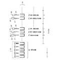
図3は、サンプラ部12の構成を示した平面図である。このサンプラ部12は、試料容器11を保持する試料ラック40、試料ラック40を移動可能に保持するベルト41及びレーン42により構成される保持部43と、保持部43のベルト41に保持された待機位置A1における試料ラック40の位置やラックIDを検出するラック検出器44とを備えている。また、分析制御部50の機構部51により保持部43のベルト41上の引出位置A2から矢印L2方向のレーン42上に引き出された試料ラック40が保持する試料容器11を検出する容器検出器45を備えている。Next, an example of the configuration of the sampler unit 12 of the analysis unit 10 will be described with reference to FIGS. 2 and 3.
FIG. 3 is a plan view showing the configuration of the sampler unit 12. The sampler unit 12 includes a
そして、ベルト41は機構部51に駆動され、ラック検出器44に検出された待機位置A1の試料ラック40を引出位置A2へ移動する。引出位置A2へ移動された試料ラック40は、容器検出器45に検出された試料容器11内の試料をサンプル分注プローブ21で吸引可能な吸引位置A4へ移動される。サンプル分注プローブ21により分注を終えた試料容器11を保持する試料ラック40は、機構部51によりL2方向とは反対方向の矢印L3方向へ移動され、ベルト41上の引出位置A2で停止する。ベルト41は、引出位置A2で停止した試料ラック40を退避位置A3へ移動する。 Then, the
次に、図2乃至図4を参照して、分析部10の測定動作について説明する。
図4は、分析部10の測定動作を説明するための図である。各反応容器19は、洗浄ユニット32により洗浄が行われる洗浄位置Wで停止する。そして、洗浄位置Wで洗浄を終えた反応容器19は、洗浄を終えたときのサイクルから所定のサイクル経過したaサイクル目において、試料吐出位置Paで停止する。サンプル分注プローブ21は、サンプラ部12の試料ラック40に保持された試料容器11内の被検試料を試料吐出位置Paの反応容器19内へ分注する。Next, the measurement operation of the analysis unit 10 will be described with reference to FIGS.
FIG. 4 is a diagram for explaining the measurement operation of the analysis unit 10. Each
aサイクル目から例えば1サイクル経過したbサイクル目において、aサイクル目に被検試料が分注された反応容器19は、第1試薬吐出位置Pbで停止する。第1試薬分注プローブ23は、第1試薬ラック15に保持された第1試薬容器13内の第1試薬を第1試薬吐出位置Pbの反応容器19内へ分注する。 For example, in the b cycle when one cycle has elapsed from the a cycle, the
bサイクル目から例えば1サイクル経過したcサイクル目において、bサイクル目に第1試薬が分注された反応容器19は、第1撹拌位置Pcで停止する。第1撹拌子25は、第1試薬吐出位置Pbの反応容器19内の被検試料及び第1試薬の混合液を撹拌する。 For example, in the c cycle when one cycle has elapsed from the b cycle, the
cサイクル目から所定のサイクル経過したdサイクル目において、cサイクル目に混合液が撹拌された反応容器19は、第2試薬吐出位置Pdで停止する。第2試薬分注プローブ27は、第2試薬吐出位置Pdの反応容器19内に分注された第1試薬が2試薬系である場合、その第1試薬と対をなす第2試薬ラック16に保持された第2試薬容器14内の第2試薬を第2試薬吐出位置Pdの反応容器19内へ分注する。 In the d cycle after a predetermined cycle has elapsed from the c cycle, the
dサイクル目から例えば1サイクル経過したeサイクル目において、dサイクル目に第2試薬が分注された反応容器19は、第2撹拌位置Peで停止する。第2撹拌子29は、第2試薬吐出位置Peの反応容器19内の被検試料、第1試薬及び第2試薬の混合液を撹拌する。 For example, in the e cycle when one cycle has elapsed from the d cycle, the
eサイクル目から所定のサイクル経過したfサイクル目において、eサイクル目に混合液が撹拌された反応容器19は、洗浄位置Wで停止する。洗浄ユニット32は、洗浄位置Wの反応容器19内を洗浄する。 In the f-th cycle when a predetermined cycle has elapsed from the e-th cycle, the
測定部31は、aサイクル目に被検試料が分注された反応容器19内の混合液を、その反応容器19がcサイクル目に第1撹拌位置Pcで停止してから、fサイクル目に洗浄位置Wで停止するまでの間のサイクル毎に回転移動中に測定する。 The
以下、図1乃至図7を参照して、自動分析装置100の動作の一例を説明する。
検査対象の被検試料を収容する試料容器11の保持位置及び検査項目を設定するために、操作部80から一般設定画面を表示させる入力が行われると、表示部72に一般設定画面が表示される。Hereinafter, an example of the operation of the automatic analyzer 100 will be described with reference to FIGS. 1 to 7.
When an input for displaying a general setting screen is performed from the
図5は、表示部72に表示された一般設定画面の一例を示した図である。この一般設定画面73は、分析部10の試料容器11を保持させるサンプラ部12の保持位置を設定する「位置」の欄と、「位置」の欄で設定された保持位置の試料容器11内の被検試料の検査項目を設定する「項目」の欄とにより構成される。また、「位置」及び「位置」の欄で設定された条件で分析を開始させるためのボタンである「一般測定」により構成される。 FIG. 5 is a diagram illustrating an example of a general setting screen displayed on the display unit 72. The general setting screen 73 includes a “position” column for setting the holding position of the sampler unit 12 that holds the
そして、操作部80からの入力により、「位置」及び「項目」の欄で設定された入力情報がシステム制御部90の記憶回路に保存されると共に表示部72に表示される。また、「一般測定」を指定する一般測定開始の入力により、システム制御部90は、「位置」及び「項目」の欄で設定された入力情報に基づいて分析制御部50、データ処理部60及び出力部70を制御し、分析動作を実行させる。 Then, by input from the
「位置」の欄は、試料ラック40を識別するラックIDを設定する「ID」の欄と、「ID」の欄で設定されたラックIDで識別される試料ラック40の試料容器11を保持するラック位置の番号を設定する「番号」の欄とにより構成される。そして、操作部80から「ID」の欄に設定する入力が行われると例えばラックIDである「1」がダイアログボックス441内に表示される。また、「番号」の欄に設定する入力が行われると、ラック位置の番号である「1」がダイアログボックス442内に表示される。 The “position” column holds the “ID” column for setting the rack ID for identifying the
「項目」の欄には、分析可能な検査項目である「項目A」、「項目B」、「項目C」、「項目D」等が表示されている。そして、表示された検査項目の中から、「位置」の欄に設定された保持位置の試料容器11内に収容される被検試料の検査項目を設定する選択入力が行われると、選択入力された例えば「項目A」、「項目B」及び「項目C」が識別して表示される。 In the “item” column, analysis items “item A”, “item B”, “item C”, “item D”, and the like that can be analyzed are displayed. When the selection input for setting the inspection item of the sample to be stored in the
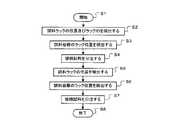
図6は、自動分析装置100の動作を示したフローチャートである。図5の一般設定画面73で保持位置及び検査項目が設定された検査対象の被検試料を収容する試料容器11が、ラックID「1」で識別される試料ラック40の番号「1」のラック位置に保持される。そして、試料容器11を保持する試料ラック40が分析部10におけるサンプラ部12のベルト41上の待機位置A1に載置された後、操作部80から一般測定開始の入力が行われると、自動分析装置100は、動作を開始する(ステップS1)。 FIG. 6 is a flowchart showing the operation of the automatic analyzer 100. The
システム制御部90は、一般設定画面73の「位置」及び「項目」の欄で設定された入力情報に基づいて分析制御部50、データ処理部60及び出力部70を制御し、分析動作を実行させる。分析制御部50の機構制御部52は、分析部10の各分析ユニットを作動させる。サンプラ部12のラック検出器44は、ベルト41に保持された待機位置A1における試料ラック40の位置及びラックIDを検出する(ステップS2)。 The
ここで、ラック検出器44が検出したラックIDが一般設定画面73で設定されたラックIDと同じである場合、ステップS3へ移行する。また、検出したラックIDが一般設定画面73で設定されたラックIDと異なる場合、ステップS8へ移行する。 If the rack ID detected by the
ベルト41は、ラック検出器44によりラックIDが「1」であると検出された試料ラック40を引出位置A2へ移動する。引出位置A2へ移動された試料ラック40は、機構部51によりL2方向へ移動される。容器検出器45は、試料ラック40に保持された試料容器11を検出する。機構制御部52は、容器検出器45からの検出信号に基づいて、容器検出器45により検出された試料容器11のラック位置を検出する(ステップS3)。 The
なお、L2方向へ移動される試料ラック40に試料容器11が保持されていない場合、ステップS8へ移行する。また、容器検出器45により検出された試料容器11のラック位置が一般設定画面73で設定されたラック位置と異なる場合、ステップS8へ移行する。 When the
サンプル分注プローブ21は、吸引位置A4で停止した試料ラック40の番号「1」のラック位置に保持される容器検出器45により検出された試料容器11内の被検試料を反応容器19内に分注する(ステップS4)。 The
ここでは、先ず「項目A」を分析するための被検試料を試料吐出位置Paに停止した反応容器19内に分注する。また、次のサイクルにおいて、前記試料容器11内の「項目B」を分析するための被検試料を試料吐出位置Paに停止した反応容器19内に分注する。更に、次のサイクルにおいて、前記試料容器11内の「項目C」を分析するための被検試料を試料吐出位置Paに停止した反応容器19内に分注する。 Here, first, a test sample for analyzing “item A” is dispensed into the
次に、操作部80から簡易設定画面を表示させる入力が行われると、表示部72に簡易設定画面が表示される。 Next, when an input for displaying the simple setting screen is performed from the
図7は、表示部72に表示された簡易設定画面の一例を示した図である。この簡易設定画面74は、図5に示した一般設定画面73から「位置」の欄を除いた「項目」の欄により構成される。また、「項目」の欄で設定された条件で分析を開始させるためのボタンである「簡易測定」により構成される。「項目」の欄には、一般設定画面73の「項目」の欄に表示された検査項目と同じ検査項目である「項目A」、「項目B」、「項目C」、「項目D」等が表示されている。そして、操作部80からの入力により、「項目」の欄で設定された入力情報がシステム制御部90の記憶回路に保存されると共に表示部72に表示されることになる。また、「簡易測定」を指定する簡易測定開始の入力により、「項目」の欄で設定された入力情報に基づいて分析制御部50、データ処理部60及び出力部70を制御し、分析動作を実行させることになる。 FIG. 7 is a diagram illustrating an example of a simple setting screen displayed on the display unit 72. The
表示部72に簡易設定画面74が表示された後、操作部80から検査項目を設定するための入力が行われると、サンプル分注プローブ21により分注が行われている場合、システム制御部90は、操作部80からの検査項目の入力を拒否することにより、簡易設定画面74での検査項目の設定を阻止する。また、サンプル分注プローブ21による分注が停止して測定部31により各反応容器19内の混合液の測定が行われている場合、システム制御部90は、操作部80からの検査項目の入力を受付け、簡易設定画面74での検査項目の設定を可能とする。 After the
なお、サンプル分注プローブ21により分注が行われている場合、操作部80からの簡易設定画面74を表示させる入力を拒否することにより、簡易設定画面74での検査項目の設定を阻止するように実施してもよい。 When dispensing is performed by the
サンプル分注プローブ21による分注が停止して測定部31により各反応容器19内の混合液の測定が行われている場合、操作部80からの選択入力により、簡易設定画面74の各欄で設定された入力情報がシステム制御部90の記憶回路に保存されると共に表示部72に表示される。ここでは、「項目」の欄で選択入力された例えば「項目A」が識別して表示される。 When dispensing by the
次に、簡易設定画面74で設定された「項目A」を分析する例えば2つの被検試料を収容する2個の試料容器11が任意の試料ラック40の任意のラック位置に保持される。2個の試料容器11を保持する試料ラック40がベルト41上の待機位置A1に載置され、ステップS3で分注を終えた退避位置A3の試料ラック40がベルト41から取り外された後の測定中において、操作部80から簡易測定開始の入力が行われると、機構制御部52は、システム制御部90から供給される簡易設定画面74で設定された検査項目の入力情報に基づいて機構部51を制御する。ラック検出器44は、簡易測定開始の入力に応じて、ベルト41に保持された待機位置A1の試料ラック40の位置を検出する(図6のステップS5)。 Next, for example, two
このように、サンプル分注プローブ21により分注が行われている場合に簡易設定画面74での検査項目の設定を阻止することにより、一般設定画面73で設定されたラックIDの試料ラック40が待機位置A1に残存している場合のその試料ラック40を簡易設定画面74で設定された検査項目を分析するための試料ラック40として検出されるのを防ぐことができる。 As described above, when the
なお、簡易測定開始の入力に応じて、ラック検出器44により試料ラック40が検出されない場合、ステップS8へ移行する。 If the
ベルト41は、ラック検出器44により位置が検出された全ての試料ラック40を引出位置A2へ移動する。引出位置A2へ移動された試料ラック40は、機構部51によりL2方向へ移動される。容器検出器45は、試料ラック40に保持された試料容器11を検出する。機構制御部52は、容器検出器45からの検出信号に基づいて、容器検出器45により検出された試料容器11のラック位置を検出する(ステップS6)。 The
機構部51は、引出位置A2へ移動された試料ラック40を容器検出器45に検出された試料容器11内の試料をサンプル分注プローブ21で吸引可能な吸引位置A4へ移動する。なお、容器検出器45によりL2方向へ移動される試料ラック40から試料容器11が検出されない場合、ステップS8へ移行する。 The
サンプル分注プローブ21は、容器検出器45により検出された全ての試料容器11内の被検試料を、簡易設定画面74で設定された検査項目に基づいて、反応容器19内に分注する(図6のステップS7)。 The
ここでは、吸引位置A4で停止した試料ラック40に保持される容器検出器45により検出された1個目の試料容器11内の「項目A」を分析するための被検試料を反応容器19内に分注する。次のサイクルにおいて、吸引位置A4で停止した試料ラック40に保持される容器検出器45により検出された2個目の試料容器11内の「項目A」を分析するための被検試料を反応容器19内に分注する。 Here, a test sample for analyzing “item A” in the
このように、サンプル分注プローブ21による分注が停止した後の測定中において、簡易設定画面74で検査項目を設定することにより、簡易測定開始の入力に応じてベルト41に保持されている待機位置A1の試料ラック40及びこの試料ラック40に保持された試料容器11を検出し、検出した全ての試料ラック40に保持される全ての試料容器11内の被検試料を、簡易設定画面74で設定された検査項目を分析するための試料として反応容器19内に分注することができる。 Thus, during the measurement after the dispensing by the
これにより、被検試料毎に試料容器11の保持位置及びその試料の検査項目を入力する操作を必要としないため、面倒な操作を軽減することができる。そして、不慣れな操作者でも容易に操作することができる。また、緊急時に迅速に操作することができる。 Thereby, since the operation which inputs the holding position of the
なお、ステップS7において、サンプル分注プローブ21により分注が行われているときに、試料容器11を保持する試料ラック40がベルト41上の待機位置A1に載置されると、待機位置A1の試料ラック40及びこの試料ラック40に保持された試料容器11を検出し、検出した全ての試料容器11内の被検試料を、簡易設定画面74で設定された検査項目を分析するための試料として反応容器19内に分注する。 In step S7, when the
サンプル分注プローブ21により分注を終えた試料容器11を保持する試料ラック40はL3方向へ移動され、ベルト41上の引出位置A2で停止する。ベルト41は、引出位置A2で停止した試料ラック40を退避位置A3へ移動する。 The
そして、サンプル分注プローブ21により分注された被検試料を含む全ての混合液の測定が終了し、その分析データが出力部70に出力された後、システム制御部90が分析制御部50、データ処理部60及び出力部70に分析の終了を指示することにより、自動分析装置100は動作を終了する(図6のステップS8)。 After the measurement of all the mixed liquids including the test sample dispensed by the
以上述べた実施形態によれば、サンプル分注プローブ21により分注が行われている場合に簡易設定画面74での検査項目の設定を阻止することにより、一般設定画面73で設定されたラックIDの試料ラック40が待機位置A1に残存している場合のその試料ラック40を簡易設定画面74で設定された検査項目を分析するための試料ラック40として検出されるのを防ぐことができる。 According to the embodiment described above, the rack ID set on the general setting screen 73 is prevented by preventing the setting of the inspection item on the
また、サンプル分注プローブ21による分注が停止した後の測定中において、簡易設定画面74で検査項目を設定することにより、簡易測定開始の入力に応じてベルト41に保持されている待機位置A1の試料ラック40及びこの試料ラック40に保持された試料容器11を検出し、検出した全ての試料ラック40に保持される全ての試料容器11内の被検試料を、簡易設定画面74で設定された検査項目を分析するための試料として反応容器19内に分注することができる。 Further, during the measurement after the dispensing by the
これにより、被検試料毎に試料容器11の保持位置及びその試料の検査項目を入力する操作を必要としないため、面倒な操作を軽減することができる。そして、不慣れな操作者でも容易に操作することができる。また、緊急時に迅速に操作することができる。 Thereby, since the operation which inputs the holding position of the
本発明のいくつかの実施形態を説明したが、これらの実施形態は、例として提示したものであり、発明の範囲を限定することを意図していない。これらの実施形態は、その他の様々な形態で実施されることが可能であり、発明の要旨を逸脱しない範囲で、種々の省略、置き換え、変更を行うことができる。これら実施形態やその変形は、発明の範囲や要旨に含まれると共に、特許請求の範囲に記載された発明とその均等の範囲に含まれる。 Although several embodiments of the present invention have been described, these embodiments are presented by way of example and are not intended to limit the scope of the invention. These embodiments can be implemented in various other forms, and various omissions, replacements, and changes can be made without departing from the scope of the invention. These embodiments and modifications thereof are included in the scope and gist of the invention, and are included in the invention described in the claims and the equivalents thereof.
A1 待機位置
A2 引出位置
A3 退避位置
A4 吸引位置
10 分析部
11 試料容器
12 サンプラ部
19 反応容器
21 サンプル分注プローブ
22 サンプル分注アーム
40 試料ラック
41 ベルト
42 レーン
43 保持部
44 ラック検出器
45 容器検出器A1 Standby position A2 Pull-out position A3 Retraction position A4 Suction position 10
Claims (4)
Translated fromJapanese前記保持手段により保持された前記試料容器内の試料を吸引して反応容器内に吐出する分注を行うサンプル分注プローブと、
前記反応容器内に分注された試料とこの試料に含まれる検査項目の成分を分析するための試薬との混合液を測定する測定手段と、
前記サンプル分注プローブにより分注が行われている場合に前記検査項目の設定を阻止し、前記サンプル分注プローブによる分注が停止して前記測定手段により測定が行われている場合に前記検査項目の設定を可能とする設定手段とを
備えたことを特徴とする自動分析装置。Holding means for movably holding a sample container in which a sample is stored;
A sample dispensing probe that performs dispensing to suck and discharge the sample in the sample container held by the holding means into the reaction container;
Measuring means for measuring a mixed solution of a sample dispensed in the reaction container and a reagent for analyzing a component of a test item included in the sample;
Setting of the inspection item is blocked when dispensing by the sample dispensing probe is performed, and the inspection is performed when dispensing by the sample dispensing probe is stopped and measurement is performed by the measuring means An automatic analyzer comprising setting means for enabling setting of items.
前記サンプル分注プローブは、前記設定手段により設定された後に前記容器検出手段により検出される全ての前記試料容器内の試料を、前記設定手段により設定された前記検査項目の試料として前記反応容器内に分注することを特徴とする請求項1に記載の自動分析装置。Having container detection means for detecting the sample container held by the holding means;
The sample dispensing probe includes all the samples in the sample container detected by the container detection means after being set by the setting means as samples of the inspection items set by the setting means. The automatic analyzer according to claim 1, wherein the automatic analyzer is dispensed into two.
前記設定手段により設定された後に前記ラック検出手段により検出される全ての前記試料ラックが前記吸引位置へ引き出されることを特徴とする請求項3に記載の自動分析装置。Rack detecting means for detecting the position of the sample rack held by the belt;
4. The automatic analyzer according to claim 3, wherein all the sample racks detected by the rack detection unit after being set by the setting unit are pulled out to the suction position.
Priority Applications (1)
| Application Number | Priority Date | Filing Date | Title |
|---|---|---|---|
| JP2011122956AJP5739236B2 (en) | 2011-05-31 | 2011-05-31 | Automatic analyzer |
Applications Claiming Priority (1)
| Application Number | Priority Date | Filing Date | Title |
|---|---|---|---|
| JP2011122956AJP5739236B2 (en) | 2011-05-31 | 2011-05-31 | Automatic analyzer |
Publications (2)
| Publication Number | Publication Date |
|---|---|
| JP2012251804A JP2012251804A (en) | 2012-12-20 |
| JP5739236B2true JP5739236B2 (en) | 2015-06-24 |
Family
ID=47524757
Family Applications (1)
| Application Number | Title | Priority Date | Filing Date |
|---|---|---|---|
| JP2011122956AActiveJP5739236B2 (en) | 2011-05-31 | 2011-05-31 | Automatic analyzer |
Country Status (1)
| Country | Link |
|---|---|
| JP (1) | JP5739236B2 (en) |
Families Citing this family (4)
| Publication number | Priority date | Publication date | Assignee | Title |
|---|---|---|---|---|
| JP6165961B2 (en) | 2013-03-15 | 2017-07-19 | アボット・ラボラトリーズAbbott Laboratories | Diagnostic analyzer with pre-process carousel and associated method |
| CN107831324B (en) | 2013-03-15 | 2021-11-19 | 雅培制药有限公司 | Automated diagnostic analyzer with rear accessible track system and related methods |
| WO2014144640A1 (en) | 2013-03-15 | 2014-09-18 | Abbott Laboratories | Automated diagnostic analyzers having vertically arranged carousels and related methods |
| JP6929636B2 (en)* | 2016-11-18 | 2021-09-01 | キヤノンメディカルシステムズ株式会社 | Automatic analyzer |
Family Cites Families (8)
| Publication number | Priority date | Publication date | Assignee | Title |
|---|---|---|---|---|
| JPS56168555A (en)* | 1980-05-30 | 1981-12-24 | Hitachi Ltd | Sample feeder |
| JPH06167502A (en)* | 1992-11-30 | 1994-06-14 | Toshiba Corp | Automatic chemical analyzer |
| JPH0676862U (en)* | 1993-03-31 | 1994-10-28 | 株式会社島津製作所 | Biochemical automatic analyzer |
| JP3031374B2 (en)* | 1999-03-10 | 2000-04-10 | 株式会社日立製作所 | Multi-item analyzer |
| JP2003329691A (en)* | 2002-05-14 | 2003-11-19 | Fuji Photo Film Co Ltd | Biochemical analyzer |
| CA2949524C (en)* | 2003-07-18 | 2017-07-04 | Bio-Rad Laboratories, Inc. | System and method for multi-analyte detection |
| JP5205124B2 (en)* | 2008-05-26 | 2013-06-05 | 株式会社東芝 | Automatic analyzer and its management method |
| JP2011066714A (en)* | 2009-09-17 | 2011-03-31 | Konica Minolta Business Technologies Inc | Image forming system |
- 2011
- 2011-05-31JPJP2011122956Apatent/JP5739236B2/enactiveActive
Also Published As
| Publication number | Publication date |
|---|---|
| JP2012251804A (en) | 2012-12-20 |
Similar Documents
| Publication | Publication Date | Title |
|---|---|---|
| JP2011232249A (en) | Automatic analyzing apparatus | |
| JP5996350B2 (en) | Automatic analyzer | |
| JP5739236B2 (en) | Automatic analyzer | |
| JP5161592B2 (en) | Automatic analyzer and maintenance method thereof | |
| JP2014066730A (en) | Automatic analyzing apparatus | |
| JP2015158410A (en) | automatic analyzer | |
| JP5134452B2 (en) | Automatic analyzer | |
| JP6521628B2 (en) | Automatic analyzer | |
| JP6289021B2 (en) | Automatic analyzer | |
| JP6758821B2 (en) | Automatic analyzer | |
| JP6675162B2 (en) | Automatic analyzer | |
| JP2012198237A (en) | Autoanalyzer | |
| JP2018132416A (en) | Autoanalyzer | |
| JP6537895B2 (en) | Automatic analyzer | |
| JP5808473B2 (en) | Automatic analyzer | |
| JP5205124B2 (en) | Automatic analyzer and its management method | |
| JP6071384B2 (en) | Automatic analyzer | |
| JP6165555B2 (en) | Automatic analyzer and its dispensing performance confirmation method | |
| JP2011257248A (en) | Automatic analyzer | |
| JP2010266245A (en) | Automatic analyzer | |
| US10908174B2 (en) | Automatic analyzing apparatus | |
| JP6430134B2 (en) | Automatic analyzer | |
| JP5180710B2 (en) | Automatic analyzer | |
| JP2013061360A (en) | Automatic analyzer | |
| JP5706252B2 (en) | Automatic analyzer |
Legal Events
| Date | Code | Title | Description |
|---|---|---|---|
| A621 | Written request for application examination | Free format text:JAPANESE INTERMEDIATE CODE: A621 Effective date:20140523 | |
| A977 | Report on retrieval | Free format text:JAPANESE INTERMEDIATE CODE: A971007 Effective date:20150212 | |
| RD02 | Notification of acceptance of power of attorney | Free format text:JAPANESE INTERMEDIATE CODE: A7422 Effective date:20150216 | |
| RD04 | Notification of resignation of power of attorney | Free format text:JAPANESE INTERMEDIATE CODE: A7424 Effective date:20150218 | |
| TRDD | Decision of grant or rejection written | ||
| A01 | Written decision to grant a patent or to grant a registration (utility model) | Free format text:JAPANESE INTERMEDIATE CODE: A01 Effective date:20150327 | |
| A61 | First payment of annual fees (during grant procedure) | Free format text:JAPANESE INTERMEDIATE CODE: A61 Effective date:20150423 | |
| R150 | Certificate of patent or registration of utility model | Ref document number:5739236 Country of ref document:JP Free format text:JAPANESE INTERMEDIATE CODE: R150 | |
| S111 | Request for change of ownership or part of ownership | Free format text:JAPANESE INTERMEDIATE CODE: R313117 | |
| R350 | Written notification of registration of transfer | Free format text:JAPANESE INTERMEDIATE CODE: R350 | |
| S533 | Written request for registration of change of name | Free format text:JAPANESE INTERMEDIATE CODE: R313533 | |
| R350 | Written notification of registration of transfer | Free format text:JAPANESE INTERMEDIATE CODE: R350 |