JP5737675B2 - Sabo weir - Google Patents
Sabo weirDownload PDFInfo
- Publication number
- JP5737675B2 JP5737675B2JP2011051762AJP2011051762AJP5737675B2JP 5737675 B2JP5737675 B2JP 5737675B2JP 2011051762 AJP2011051762 AJP 2011051762AJP 2011051762 AJP2011051762 AJP 2011051762AJP 5737675 B2JP5737675 B2JP 5737675B2
- Authority
- JP
- Japan
- Prior art keywords
- dam
- water
- sabo
- slit
- channel
- Prior art date
- Legal status (The legal status is an assumption and is not a legal conclusion. Google has not performed a legal analysis and makes no representation as to the accuracy of the status listed.)
- Active
Links
Images


Landscapes
- Barrages (AREA)
Description
Translated fromJapanese本発明は河川上流や山岳渓谷に設置される砂防堰の堆砂抑制と水生生物の往来確保、及び、ダムや湖沼、かんがい用貯水池、雨水貯留池の堆砂や泥土、ヘドロの排出に関するものである。 The present invention relates to sediment control of a sabo weir installed in an upstream river or a mountain valley, securing traffic of aquatic organisms, and discharge of sediment, mud and sludge from dams, lakes, irrigation reservoirs, rainwater reservoirs. is there.
従来の砂防堰は不透過型砂防堰が多く設置され、堰提には底部及び中間高さ位置に複数箇所の貫通した水抜き孔を設け、小さな礫石や泥土は流下させるべく構成されているけれども、水抜き孔は目詰りや閉塞を生じやすく、現在では、スリット型、或いは透過型と称されるものが採用され、大きすぎる礫石は阻止するが、小さな礫や泥土は流下させて、河床や海浜の維持や、水生生物の生育に役立てる等の配慮がなされるようになってきた。 The conventional sabo dams are often equipped with impervious sabo dams, and the dams are provided with multiple drainage holes at the bottom and at intermediate heights so that small gravel stones and mud can flow down. Water drainage holes are prone to clogging and clogging, and what is now called slit-type or transmission-type is adopted to prevent too large gravel, but small gravel and mud are allowed to flow down, Consideration has been given to maintaining the beach and to help aquatic organisms grow.
新設される透過型の砂防堰では多くの問題が解決されているとしても、不透過型の砂防堰が必要とされる所もあり、また、多くの既設不透過型砂防堰が存在し、集中豪雨等で大量の崩落があれば、礫石混じり泥土が砂防堰内に一気に流入して、砂防堰提の水抜き孔は礫石や流木のために閉塞されやすく、砂防堰内は堆積沈殿物により短期間で満杯になりやすい問題がある。Even though many problems have been solved in the newly established transmission-type sabo dams, there are places where impermeable-type sabo dams are required, and there are many existing non-permeable-type sabo dams. If there is a large amount of collapse due to heavy rain, mud soil mixed with conglomerate flows into the sabo weir at once, and the drainage hole of the sabo dam tends to be clogged with conglomerate and driftwood, and the sabo weir is short-termed by sedimentary sediment. There is a problem that tends to fill up between.
近年は川床や海浜の状況に合わせて流砂量をコントロールする研究もなされており、これに利用しやすい砂防堰が必要になることや、沢に設けられた砂防堰はその高さゆえに、水生生物の往来をまったく困難にしてしまう改善されるべき問題点もある。In recent years, research has been conducted to control the amount of sand flow according to the conditions of the riverbed and the beach, and it is necessary to use an easy-to-use sabo weir. There is also a problem that needs to be improved that makes it difficult to come and go.
また、ダムや湖沼、かんがい用貯水池、雨水貯留池においても、堆砂の排出、堆積泥土の排出、ヘドロの排出等の問題がある。In addition, dams, lakes, irrigation reservoirs, and rainwater reservoirs also have problems such as sediment discharge, sediment mud discharge, and sludge discharge.
本発明では、砂防堰に礫石泥土が一気に流入した場合においても、堰提を貫通した水抜き孔を閉塞させないために、堰提底部に設けられた水抜き孔の堰内側壁面に、水抜き孔から上方に向かって堰提を越えない高さの筒状体補給水塔を立設し、該補給水塔には、礫石が流入し難い補給水塔の壁面側に、全高さにわたって縦方向に多数の孔を配列して窄穴することや、1条か2条の縦方向スリット状長孔を開窄した吸水口を設け、ほぼ全高さ位置からの吸水を可能にする。 In the present invention, even when gravel stone mud flows into the sabo dam at once, the drainage hole is formed on the inner wall surface of the drainage hole provided in the bottom of the dam in order not to block the drainage hole penetrating the dam. A cylindrical supplementary water tower with a height that does not exceed the dam from the upper side to the upper side is installed, and there are a number of holes in the vertical direction over the entire height on the wall surface of the supplementary water tower where conglomerate is difficult to flow. Are arranged to form a constricted hole, or a water absorption port is formed by constricting one or two longitudinal slit-like elongated holes, thereby enabling water absorption from almost the entire height.
該補給水塔は、水抜き孔に大量の礫石が押し寄せ、泥水が水抜き孔に流入し難くなったときに、礫石を防御した補給水塔内水を水抜き孔に流入させるものであり、下方端は水抜き孔に近接した位置で開放する。
例えば、水抜き孔の上辺に堰提から一定長さ庇状にカバーを突出させ、該カバーの両側に2体の補給水塔を設け、下方端を水抜き孔の両側に開放することや、水抜き孔を一定長さ上流側に突出させる形の吸泥管を設け、該吸泥管の下方を開窄して吸泥口を開口させると共に、補給水塔下方端の補給水を吸泥管先端に導き、吸泥管の上流側先端部に注入する。The replenishing water tower is configured to allow the water in the replenishing water tower, which has protected the gravel stones, to flow into the water drain hole when a large amount of gravel stones are pushed into the water drain hole and it is difficult for the muddy water to flow into the water drain hole. Opens at a position close to the drain hole.
For example, a cover is projected from the weir over the upper side of the drainage hole in a certain length, and two makeup water towers are provided on both sides of the cover, and the lower end is opened on both sides of the drainage hole, A mud pipe with a shape that allows the vent hole to protrude upstream by a certain length is provided, the lower part of the mud pipe is narrowed to open the mud opening, and the make-up water at the lower end of the make-up water tower is supplied to the tip of the mud pipe And inject it into the upstream end of the mud pipe.
また、万一補給水塔の下方部分が埋没した時にも、該補給水塔のスリット状吸水口からの上方水の流入水勢によって、スリット状吸水口周りの堆砂を洗掘流入させて排出し、上方水が水抜き孔へ直接流入する水路を開窄しやすくする。In addition, even if the lower part of the make-up water tower is buried, due to the inflow water of the upper water from the slit-like water intake of the make-up water tower, the sediment around the slit-like water intake is scoured and discharged, It makes it easy to open the water channel where water flows directly into the drain hole.
次に、本発明では、水抜き孔をすぐに閉塞させないために、水抜き孔の上流側砂防堰内底面において、断面形状がU字形やV字形、凹型や欠円状の溝状体を伏せた形で、下縁設置面にスリット状の吸泥口隙間を設けた覆水路を上流方向に向け延伸配設して、流入礫石大きさを制限すると共に、水抜き孔流入口面積の増大を図る。
該覆水路の下流側端部は、堰提の水抜き孔位置に合せて堰提に当接させることや、補給水塔の上流側端面と水抜き孔の最大通過径以下の隙間を設けた位置までとすることができる。Next, in the present invention, in order not to close the drain hole immediately, the groove-shaped body having a U-shaped, V-shaped, concave or not-circular cross section is turned down on the bottom surface inside the sabo dam upstream of the drain hole. In this way, a drainage channel with a slit-shaped mud opening on the lower edge installation surface is extended and arranged in the upstream direction to limit the size of the inflow gravel and increase the drain hole inlet area. Plan.
The downstream end of the flood channel is in contact with the dam according to the position of the drainage hole of the dam, or the position where the upstream end surface of the make-up water tower and the gap less than the maximum passage diameter of the drainage hole are provided. Can be up to.
覆水路を堰内底面に沿わせ、流下勾配を付して上流側に向け大きく延伸することは、洪水時に覆水路の上流側が埋没しても、該覆水路内は外部から保護された安静な状態で、濃度の低い水が貯留されることに加え、長い距離間のスリット状吸泥口からの礫間、及び、砂粒間浸透水も期待できるために、補吸水塔に替わり水抜き孔への補給水が行えて、覆水路だけのシンプルな構成の堆砂排出装置とすることができる。Extending the floodway along the bottom of the weir and extending it toward the upstream side with a downflow gradient means that even if the upstream side of the floodway is buried during a flood, the inside of the floodway is protected from the outside. In addition to storing low-concentration water in the state, in addition to the gravel from the slit-shaped mud suction port for a long distance and the permeation water between the sand grains can be expected, instead of the auxiliary water absorption tower to the drain hole Therefore, it is possible to provide a sediment discharge device having a simple configuration with only a cover channel.
また、上流側に向けて延伸した覆水路は、砂防堰内滞留水が無くなった後に、砂防堰への流入水が堆砂上を水抜き孔に向けて流下するようになり、流入量と流速に応じて堆砂が洗掘されて流下し、洗掘が進むに連れ、流下水は次第に上流側スリット状吸泥口から覆水路内に流入するようになり、水抜き孔から排砂、排水され、砂防堰内の最低流水路床を覆水路の設置床面にキープして、覆水路上流端までの堆砂排出が行える。In addition, the drainage channel extending toward the upstream side causes the inflow water to the sabo weir to flow down on the sediment toward the drain hole after the accumulated water in the sabo dam disappears. In response, the sediment is scoured and flowed down, and as the scouring progressed, the sewage gradually began to flow into the cover channel from the upstream slit-shaped mud suction port, and was discharged and drained from the drain hole. By keeping the lowest flow channel floor in the sabo weir on the floor of the cover channel, sediment can be discharged up to the upstream end of the channel.
前記する覆水路の堆砂排出の特性は、透過型砂防堰においても堰提を開窄した通水スリットに合せた上流側に、覆水路を上流側に向け長く延伸配設することによって、砂防堰内の最低流水路床を覆水路の設置面にキープした堆砂排出が行える。
尚、この場合の覆水路の下流端位置は、堰提から下流側に突出させることや、堰提上流側に通水スリット巾以下の隙間を設けた位置までとすることができる。The characteristics of sediment discharge in the above-mentioned water-carrying channel are the same as those of the transmission type sabo dam. The sediment can be discharged by keeping the lowest flow channel in the weir to the surface of the cover channel.
In this case, the downstream end position of the water covering channel can be projected from the dam to the downstream side or to a position where a gap less than the width of the water passage slit is provided on the upstream side of the dam.
また、ダムにおける堆砂排出においても、ダム底に設けられた土吐きゲートに合せて、覆水路を上流側に向けて延伸配設し、ダム水位を下げて、ダムへの流入水を土吐きゲートに向けて流下排水させることによって、延伸した覆水路の上流端までの、覆水路設置床面をキープした堆砂の洗掘排砂が行える。In addition, when discharging sediment in the dam, the drainage channel is extended and arranged upstream to match the earth discharge gate provided at the bottom of the dam, the dam water level is lowered, and the inflow water to the dam is discharged. By letting it flow down toward the gate, it is possible to scour and discharge the sediment that keeps the floor surface of the cover channel up to the upstream end of the extended cover channel.
更に、本発明では、水生生物が砂防堰を越えて往来できるように、水抜き孔の下流側に、水抜き孔の高さに合せた魚道を下流の川床に向けて配設し、該魚道には、這い上がる習性の水生生物のために蟹ロープ(麻縄)や藻縄(麻縄に藻草に似せた多数の紐を編みこんだ縄とする)を魚道の全長にわたって配設することができる。Furthermore, in the present invention, in order to allow aquatic organisms to pass over the sabo dam, a fishway that matches the height of the water drainage hole is arranged on the downstream side of the water drainage hole toward the downstream riverbed. For the aquatic habits of climbing habits, it is possible to arrange cocoon ropes (hemp ropes) and algae ropes (with ropes woven with a lot of strings resembling algae in the hemp rope) over the entire length of the fishway it can.
また、本発明では、河川流砂量をコントロールするために、砂防堰水抜き孔の下流側端にバルブを設け、閉止することで堰内堆砂の流出を止め、開放することで堆砂を流出させ、下流河川流砂のコントロールを自然に近い形で行う。Further, in the present invention, in order to control the amount of river sand flow, a valve is provided at the downstream end of the sabo weir drain hole and closed to stop outflow of sediment in the weir and open to discharge sediment. And control the river sediments in the downstream river in a form close to nature.
上述する本発明の補給水塔を備えた砂防堰においては、豪雨時の洪水によって大量の礫石が一気に流入した場合、泥流は堰提を超えて下流に流出すると同時に、堰内においては礫石が急速に沈降しつつ、次々に水抜き孔に押し寄せ、集積する形で、水抜き孔は閉塞されやすい状態になるけれども、補給水塔から比較的にきれいな上方水が水抜き孔に補給されるようになり、完全な閉塞を生じさせることなく砂防堰内泥土の排出が続けられる。In the sabo dam equipped with the replenishment water tower of the present invention described above, when a large amount of conglomerate flows in at a stroke due to a flood during heavy rain, the mudflow flows downstream beyond the dam and at the same time the conglomerate rapidly The water drainage holes are likely to be clogged in the form of being pushed down and gathering one after another while sinking into the drainage water, but relatively clean upward water will be replenished to the water drainage holes from the make-up water tower. The discharge of mud in the sabo dam continues without causing complete blockage.
洪水後の砂防堰内滞留水がなくなった後は、堰内に礫石泥土が残るけれども、その後の降雨や、上流からの流入水によって自然に洗掘流下して、砂防堰内には大きな礫は残るけれども、小さな礫石泥土は水抜き孔より下流堰提外に排除され、砂防堰内堆砂量は著しく軽減される。After the flood, the accumulated water in the sabo weir remains, but gravel mud remains in the weir. Although it remains, the small gravel mud is removed outside the drainage weir from the drainage hole, and the amount of sediment in the sabo weir is significantly reduced.
覆水路を備えた砂防堰の水抜き孔は、大きな礫石が多量に流入した場合や、流木の流入があった場合においても、礫石大きさがスリット状吸泥口で制限され詰りを生じることはなく、スリット状吸泥口面積も覆水路の延伸で充分なものにできやすく、通過させる礫の大きさは、水抜き孔の径及びスリット状吸泥口高さを共に大きくすることで自由に対応できる。The drainage hole of a sabo weir with a floodway is clogged because the size of the gravel is limited by the slit-shaped mud suction port even when a large amount of large gravel stone flows in or when a driftwood flows in. It is easy to make the slit-shaped mud mouth area sufficient by extending the water-covered channel, and the size of gravel to pass through can be freely increased by increasing both the diameter of the drain hole and the height of the slit-shaped mud hole. Yes.
更に、覆水路を上流側に向けて長く伸延することにより、流入口から水抜き孔へ向けた自然な洗掘流下勾配ではなく、配設した覆水路の設置面を最低流水路床とした堆砂排出が行えて、残留堆砂量を著しく抑制でき、仮に、残留堆砂が中高に堆積して覆水路を埋没させても、覆水路内水路は確保されて砂防堰内ダムの発生を防止するばかりでなく、覆水路内流水はスリット状吸泥口から埋没した部分の外部堆砂を洗掘、崩落流入させて排除し開放させることができる。Furthermore, by extending the cover channel long toward the upstream side, it is not a natural scouring slope down from the inlet to the drain hole, but the installed surface of the installed cover channel is the minimum flow channel floor. Sand can be discharged and the amount of residual sediment can be remarkably suppressed. Even if residual sediment accumulates at a medium to high level and the cover channel is buried, the cover channel is secured and the occurrence of a dam in the sabo dam is prevented. In addition, the flowing water in the cover channel can be removed by scouring and collapsing the portion of the external sediment buried through the slit-shaped mud suction port and releasing it.
また、覆水路を上流側に向けて長く延伸することは、洪水時に覆水路が埋没した時にも、覆水路内に濃度の低い水を貯留して、また、浸透水も得やすく、補給水塔を不要にした覆水路を伸延しただけのシンプルな堆砂排出装置にできる。In addition, extending the spillway toward the upstream side means that even when the spillway is buried during floods, low-concentration water is stored in the spillway and it is easy to obtain osmotic water. It can be a simple sediment discharge device that simply extends a covered channel.
透過型砂防堰内に覆水路を配設した場合においても、伸延した覆水路の上流端までの最低流水路床を覆水路の設置面にキープした堆砂排出が行えて、残留堆砂量を著しく軽減でき、加えて、洪水時には転がりながら流下する大きな礫が流れ方向に沿った覆水路に緩衝され、堰提への直接的な衝撃を緩和する。Even when a cover channel is installed in the transmission type sabo dam, the sediment flow can be discharged by keeping the lowest flow channel floor up to the upstream end of the extended cover channel on the installation surface of the cover channel. In addition, it can remarkably reduce, and in addition, large gravel that rolls down during a flood is buffered in a floodway along the flow direction, reducing the direct impact on the weir.
更に、ダム底の土吐きゲートに合せて設けた覆水路においても、最低流下水路床を覆水路設置床面にキープして、覆水路上流端までの堆砂排出が行え、特に、ダム底が緩やかな傾斜の場合や、平坦部が長いダムにおいての残留堆砂軽減効果は甚大である。Furthermore, even in the diversion channel provided along with the earth discharge gate at the bottom of the dam, sediment can be discharged up to the upstream end of the diversion channel by keeping the lowest runoff diversion floor to the floor of the diversion channel. In the case of a gentle slope or in a dam with a long flat part, the residual sediment reduction effect is enormous.
次に、水抜き孔下流側に魚道を設けた本発明においては、大量の降雨時には水抜き孔からの流出水が強烈な噴流となり役立たないものとなるが、気候と天気の移り変わりの中で、沢水の流れと共に水抜き孔からの流量が変化し役に立つ時期もあり、魚道、水抜き孔へと遡上した生物は、配設した覆水路内や、自然に洗掘された堆砂中の水路、或いは、礫間を更に上流に遡上往来でき、一般河川の魚道とは少し趣は異なるが、当該地域の水生生物、例えば、沢蟹、小形サンショウウオ、ヤマメに砂防堰を越える小さな沢を提供する効果がある。Next, in the present invention in which a fishway is provided on the downstream side of the drainage hole, the effluent water from the drainage hole becomes a strong jet during the heavy rain, but it is not useful, but in the change of climate and weather, There are times when the flow from the drainage holes changes with the flow of the stream, and there are times when it is useful, and the organisms that have gone up to the fishway and drainage holes can be found in the drainage channels and in the scoured sand that has been scoured naturally. It can go up and down the waterway or between the gravel, and it is a little different from the fishway of general rivers, but it provides aquatic organisms in the area, for example, swamps, small salamanders, yamame trout, and small swamps that exceed the sabo dam There is an effect to.
水抜き孔にバルブを設けた本発明砂防堰においては、必要に応じて砂防堰内に礫石泥土を貯留することや、必要な時期に開放して、降雨や上流からの流入水量に応じて流出させて下流河川に流砂として供給し、最も自然な状態での河川流砂のコントロールが行える効果がある。In the present sabo dam with a valve in the drain hole, it is possible to store gravel stone mud in the sabo dam as needed, or to open it when necessary, and to discharge according to rainfall or the amount of inflow water from upstream. It can be supplied to the downstream river as sediment and can control the river sediment in the most natural state.
以下、本発明の実施形態を図1〜図9に基づいて説明する。 Hereinafter, embodiments of the present invention will be described with reference to FIGS.
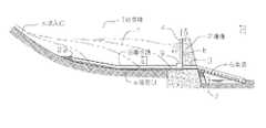
本発明の第1実施例は、図1、図2、図3に図示するように、堰提2の上流側壁面に水抜き孔位置にあわせて補給水塔4を立設し、砂防堰1内に一定長さの覆水路8を堰内底面に沿わせ、流下勾配を設けて配設し、上流端には石受け22を設けて礫石から覆水路8を防御し、下流側端は、補給水塔4の下方端に水抜き孔を囲う形に設けたカバー9内に挿入連通させたものである。In the first embodiment of the present invention, as shown in FIGS. 1, 2, and 3, a
本実施例の場合は、洪水時には補給水塔4の働きにより水抜き孔3の閉塞を防止して、濁流礫石を水抜き孔3から流出させ、洪水後においては流入口nからの降雨や上流からの流入水を堆砂予想線fで示す堆砂上を自然に流下させることにより、堆砂を自然に洗掘流下させて水抜き孔3から流出させる。
初期においては、砂防堰1の流入口nから水抜き孔3に至る自然な流下勾配であるが、堆砂の洗掘の進行に伴い、順次覆水路8の上流側吸泥口aから流入し排出されるようになり、覆水路の上流端に至る堆砂排出が行える。In the case of this embodiment, during the flood, the
In the initial stage, it is a natural downflow gradient from the inlet n of the
また、図1においては、堰提2の水抜き孔3下流側に連接した魚道6は、下流方向に向けた魚道としているけれども、洪水時には上方の越流水勢と水抜き孔3からの激しい流出水勢に加え、混入する礫石に魚道6が損傷しやすいために、魚道7で示すように堰提2の壁面に沿わせる形に配設するほうが良く、図示はしていないけれども覆水路8の上流端に締結した藻縄を魚道6の下流端に至るまで配設する。 In FIG. 1, the fishway 6 connected to the downstream side of the
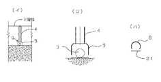
第2実施例は図4及び図5に示すように、砂防堰1の堰提2内側壁面に、水抜き孔3位置にあわせて補給水塔4を立設したものであり、下方に連接する吸泥管5と共に鋼管と鋼材で構成したものである、補給水塔4の吸水口bから流入した補給水は、吸泥管5の上部に設けた通水路dによって導かれ、吸泥管5の先端部eから吸泥管5内に給水する。
該給水量は、吸泥口cの吸入抵抗が大きくなれば多量に、小さくなれば少量の補給水が注入される。In the second embodiment, as shown in FIGS. 4 and 5, a make-up
The amount of water supplied is large when the suction resistance of the mud suction port c is increased, and a small amount of makeup water is injected when it is decreased.
堰提2の水抜き孔3下流端にはバルブ10を連接して開閉し、下流河川流砂のコントロール時に使用する。 A
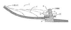
図7及び図8に示す第3実施例は、砂防堰1の堰提2の底部に開窄された矩形の水抜き孔13に合せて、図6に示すコンクリートブロック24を配列して覆水路18、及び補給水塔14を構成したものであり、覆水路18の下流端と補給水塔14の間には、覆水路18の下辺の吸泥口aのスリット高さと同程度の隙間を設けて配設したものであり、水抜き孔13の流入口周辺面積の増加と施行の容易さを求めたものである。7 and 8, the
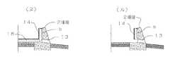
また、図9の(ヌ)に示すものは実施例3の覆水路18と補給水塔14の交差部分の構成を変えた実施例の堰提2部分の断面図であり、図9の(ル)は実施例3の覆水路18を設けない実施例の堰提2部分の断面図であり、水抜き孔13の閉塞を防止する最低限の装置である。Moreover, what is shown in (nu) of FIG. 9 is a cross-sectional view of the dam 2 portion of the embodiment in which the configuration of the crossing portion of the
本発明の砂防堰は、砂防堰が堆砂で満杯になるまでの期間を著しく改善して、土石流災害を緩和すると共に、水生生物と河川、海浜環境の回復保全に大きく貢献するものである。
また、ダムにおける残留堆砂量の軽減、かんがい用溜池等における残留ヘドロ量の軽減は貯留容量の回復ばかりでなく、すべての作業が天然自然に行える省力、省エネの経済的効果は大なるものがある。The sabo weir of the present invention significantly improves the period until the sabo dam is filled with sediment, mitigates debris flow disasters, and greatly contributes to the restoration and maintenance of aquatic organisms, rivers and beach environments.
In addition, reducing the amount of residual sediment in dams and reducing residual sludge in irrigation ponds, etc. not only restores storage capacity, but also saves labor and can save all the work naturally. is there.
1 砂防堰
2 砂防堰の堰提
3、13 砂防堰の水抜き孔
4、14 補給水塔
5 吸泥管
6 魚道
7 魚道
8、18 覆水路
9 補給水塔下方端に水抜き孔を覆う形に設けたカバー
10 バルブ
21 ベースプレート
22 石受けブロック
23 石受けブロック
a 吸泥口
b 補給水塔の吸水口
c 吸泥口
d 補給水の水路
e 吸泥管先端の補給水の注水口
f 砂防堰内堆砂の堆砂予想線1 Sabo Weir 2
Claims (5)
Translated fromJapanesePriority Applications (1)
| Application Number | Priority Date | Filing Date | Title |
|---|---|---|---|
| JP2011051762AJP5737675B2 (en) | 2011-03-09 | 2011-03-09 | Sabo weir |
Applications Claiming Priority (1)
| Application Number | Priority Date | Filing Date | Title |
|---|---|---|---|
| JP2011051762AJP5737675B2 (en) | 2011-03-09 | 2011-03-09 | Sabo weir |
Publications (2)
| Publication Number | Publication Date |
|---|---|
| JP2012188829A JP2012188829A (en) | 2012-10-04 |
| JP5737675B2true JP5737675B2 (en) | 2015-06-17 |
Family
ID=47082288
Family Applications (1)
| Application Number | Title | Priority Date | Filing Date |
|---|---|---|---|
| JP2011051762AActiveJP5737675B2 (en) | 2011-03-09 | 2011-03-09 | Sabo weir |
Country Status (1)
| Country | Link |
|---|---|
| JP (1) | JP5737675B2 (en) |
Families Citing this family (8)
| Publication number | Priority date | Publication date | Assignee | Title |
|---|---|---|---|---|
| CN103938591B (en)* | 2014-02-27 | 2015-12-02 | 黄河水利委员会河南黄河河务局 | A kind of method reducing reservoir on hyperconcentration river alluvial |
| CN103938578B (en)* | 2014-02-27 | 2015-09-30 | 黄河水利委员会河南黄河河务局 | A kind of reservoir on hyperconcentration river subtract silt system |
| DE102014014009A1 (en)* | 2014-09-25 | 2016-03-31 | Dietrich Bartelt | Process for the artificial erosion of dams |
| CN104831689B (en)* | 2015-05-28 | 2016-08-17 | 杨建能 | A kind of automatic flood control, the water intake facilities of anti-alluvial of blowdown |
| JP6689503B2 (en)* | 2016-01-25 | 2020-04-28 | 井上 虎男 | Lifting sand mud device using covered channel |
| JP6896206B2 (en)* | 2016-01-25 | 2021-06-30 | 井上 虎男 | Divided vertical channel mud pumping device |
| JP7593226B2 (en) | 2021-05-17 | 2024-12-03 | 株式会社大林組 | Water intake and sand discharge device |
| CN114837143A (en)* | 2022-06-09 | 2022-08-02 | 中国电建集团中南勘测设计研究院有限公司 | Flip bucket and drainage structure thereof |
Family Cites Families (8)
| Publication number | Priority date | Publication date | Assignee | Title |
|---|---|---|---|---|
| JPH0529227Y2 (en)* | 1989-12-27 | 1993-07-27 | ||
| JP2981570B2 (en)* | 1990-11-15 | 1999-11-22 | 社団法人ダム・堰施設技術協会 | Fish road |
| JP3747296B2 (en)* | 1996-04-26 | 2006-02-22 | 財団法人ダム水源地環境整備センター | Floating fishway equipment |
| JP3895505B2 (en)* | 1999-06-24 | 2007-03-22 | 虎男 井上 | Equipment for collecting and transferring sediment |
| JP4663145B2 (en)* | 2001-03-30 | 2011-03-30 | 橋本 徹 | Underwater sediment flow method using hydrostatic pressure, pipe with opening and underwater sediment flow facility |
| JP3860029B2 (en)* | 2001-12-26 | 2006-12-20 | 財団法人砂防・地すべり技術センター | Transmission type sabo dam and manufacturing method thereof |
| JP4798523B2 (en)* | 2006-06-13 | 2011-10-19 | 虎男 井上 | A device that recovers and removes long-range precipitates without turbidity. |
| JP4678893B1 (en)* | 2010-08-26 | 2011-04-27 | 秀樹 中込 | Intake mechanism of Sabo Dam |
- 2011
- 2011-03-09JPJP2011051762Apatent/JP5737675B2/enactiveActive
Also Published As
| Publication number | Publication date |
|---|---|
| JP2012188829A (en) | 2012-10-04 |
Similar Documents
| Publication | Publication Date | Title |
|---|---|---|
| JP5737675B2 (en) | Sabo weir | |
| JP5867918B2 (en) | A device that pumps and discharges deep water from a dam lake | |
| LARINIER | Fish passage through culverts, rock weirs and estuarine obstructions | |
| KR100783747B1 (en) | Drainage structure in tunnel | |
| KR100780743B1 (en) | Series of siphon channel channels equipped with air discharge means having a height difference | |
| KR20140017412A (en) | An ecology river | |
| JP3628302B2 (en) | Sabo Dam | |
| KR100619459B1 (en) | River sluice automatically adjusted according to water level | |
| JP7593226B2 (en) | Water intake and sand discharge device | |
| US1376889A (en) | Lake or pond | |
| TWI610008B (en) | A kind of remediation structure technology of hydraulic ecosystem | |
| KR100607455B1 (en) | Underwater walkway for smooth use of river water | |
| KR100572507B1 (en) | Overflow discharge chamber | |
| JP4443869B2 (en) | Underground irrigation system | |
| KR100571724B1 (en) | Sliding Gate | |
| JP5397728B2 (en) | Leveling method for rivers, etc. | |
| JP4118770B2 (en) | Sabo dam storage and drainage structure | |
| KR101008462B1 (en) | Fish-fishing device for fry | |
| KR100674355B1 (en) | Installation structure of water supply tower | |
| KR200341022Y1 (en) | Embankment draining structure for preventing river flooding | |
| RU2623047C1 (en) | Flood spillway for dams and other water supply facilities | |
| KR100424282B1 (en) | The automatic system for elimination of material desposited inside a underwater beam | |
| KR101555657B1 (en) | An undercurrent block for flow control of river | |
| KR100608172B1 (en) | Freshwater lake construction and construction method | |
| JP3075109B2 (en) | Water intake structure from storage structure to fishway |
Legal Events
| Date | Code | Title | Description |
|---|---|---|---|
| A621 | Written request for application examination | Free format text:JAPANESE INTERMEDIATE CODE: A621 Effective date:20140219 | |
| A977 | Report on retrieval | Free format text:JAPANESE INTERMEDIATE CODE: A971007 Effective date:20140821 | |
| A131 | Notification of reasons for refusal | Free format text:JAPANESE INTERMEDIATE CODE: A131 Effective date:20140916 | |
| A521 | Request for written amendment filed | Free format text:JAPANESE INTERMEDIATE CODE: A523 Effective date:20141030 | |
| TRDD | Decision of grant or rejection written | ||
| A01 | Written decision to grant a patent or to grant a registration (utility model) | Free format text:JAPANESE INTERMEDIATE CODE: A01 Effective date:20150203 | |
| A61 | First payment of annual fees (during grant procedure) | Free format text:JAPANESE INTERMEDIATE CODE: A61 Effective date:20150210 | |
| A59 | Written plea | Free format text:JAPANESE INTERMEDIATE CODE: A59 Effective date:20150413 | |
| A61 | First payment of annual fees (during grant procedure) | Free format text:JAPANESE INTERMEDIATE CODE: A61 Effective date:20150413 | |
| R150 | Certificate of patent or registration of utility model | Ref document number:5737675 Country of ref document:JP Free format text:JAPANESE INTERMEDIATE CODE: R150 | |
| R250 | Receipt of annual fees | Free format text:JAPANESE INTERMEDIATE CODE: R250 | |
| R250 | Receipt of annual fees | Free format text:JAPANESE INTERMEDIATE CODE: R250 | |
| R250 | Receipt of annual fees | Free format text:JAPANESE INTERMEDIATE CODE: R250 | |
| R250 | Receipt of annual fees | Free format text:JAPANESE INTERMEDIATE CODE: R250 | |
| R250 | Receipt of annual fees | Free format text:JAPANESE INTERMEDIATE CODE: R250 | |
| R250 | Receipt of annual fees | Free format text:JAPANESE INTERMEDIATE CODE: R250 | |
| R250 | Receipt of annual fees | Free format text:JAPANESE INTERMEDIATE CODE: R250 | |
| R250 | Receipt of annual fees | Free format text:JAPANESE INTERMEDIATE CODE: R250 |