JP5730975B2 - Electric vehicle - Google Patents
Electric vehicleDownload PDFInfo
- Publication number
- JP5730975B2 JP5730975B2JP2013213707AJP2013213707AJP5730975B2JP 5730975 B2JP5730975 B2JP 5730975B2JP 2013213707 AJP2013213707 AJP 2013213707AJP 2013213707 AJP2013213707 AJP 2013213707AJP 5730975 B2JP5730975 B2JP 5730975B2
- Authority
- JP
- Japan
- Prior art keywords
- unit
- collision
- power storage
- battery
- storage unit
- Prior art date
- Legal status (The legal status is an assumption and is not a legal conclusion. Google has not performed a legal analysis and makes no representation as to the accuracy of the status listed.)
- Active
Links
- 238000001514detection methodMethods0.000claimsdescription22
- 238000000034methodMethods0.000description16
- 239000004065semiconductorSubstances0.000description8
- HBBGRARXTFLTSG-UHFFFAOYSA-NLithium ionChemical compound[Li+]HBBGRARXTFLTSG-UHFFFAOYSA-N0.000description3
- 229910001416lithium ionInorganic materials0.000description3
- 239000003990capacitorSubstances0.000description2
- 230000006866deteriorationEffects0.000description2
- 238000010586diagramMethods0.000description2
- 229910052987metal hydrideInorganic materials0.000description2
- 229910052759nickelInorganic materials0.000description2
- PXHVJJICTQNCMI-UHFFFAOYSA-NnickelSubstances[Ni]PXHVJJICTQNCMI-UHFFFAOYSA-N0.000description2
- -1nickel metal hydrideChemical class0.000description2
- 230000001133accelerationEffects0.000description1
- 230000000903blocking effectEffects0.000description1
- 238000007599dischargingMethods0.000description1
- 238000012986modificationMethods0.000description1
- 230000004048modificationEffects0.000description1
Images


Classifications
- B—PERFORMING OPERATIONS; TRANSPORTING
- B60—VEHICLES IN GENERAL
- B60L—PROPULSION OF ELECTRICALLY-PROPELLED VEHICLES; SUPPLYING ELECTRIC POWER FOR AUXILIARY EQUIPMENT OF ELECTRICALLY-PROPELLED VEHICLES; ELECTRODYNAMIC BRAKE SYSTEMS FOR VEHICLES IN GENERAL; MAGNETIC SUSPENSION OR LEVITATION FOR VEHICLES; MONITORING OPERATING VARIABLES OF ELECTRICALLY-PROPELLED VEHICLES; ELECTRIC SAFETY DEVICES FOR ELECTRICALLY-PROPELLED VEHICLES
- B60L3/00—Electric devices on electrically-propelled vehicles for safety purposes; Monitoring operating variables, e.g. speed, deceleration or energy consumption
- B60L3/12—Recording operating variables ; Monitoring of operating variables
- B—PERFORMING OPERATIONS; TRANSPORTING
- B60—VEHICLES IN GENERAL
- B60L—PROPULSION OF ELECTRICALLY-PROPELLED VEHICLES; SUPPLYING ELECTRIC POWER FOR AUXILIARY EQUIPMENT OF ELECTRICALLY-PROPELLED VEHICLES; ELECTRODYNAMIC BRAKE SYSTEMS FOR VEHICLES IN GENERAL; MAGNETIC SUSPENSION OR LEVITATION FOR VEHICLES; MONITORING OPERATING VARIABLES OF ELECTRICALLY-PROPELLED VEHICLES; ELECTRIC SAFETY DEVICES FOR ELECTRICALLY-PROPELLED VEHICLES
- B60L3/00—Electric devices on electrically-propelled vehicles for safety purposes; Monitoring operating variables, e.g. speed, deceleration or energy consumption
- B60L3/0007—Measures or means for preventing or attenuating collisions
- B—PERFORMING OPERATIONS; TRANSPORTING
- B60—VEHICLES IN GENERAL
- B60L—PROPULSION OF ELECTRICALLY-PROPELLED VEHICLES; SUPPLYING ELECTRIC POWER FOR AUXILIARY EQUIPMENT OF ELECTRICALLY-PROPELLED VEHICLES; ELECTRODYNAMIC BRAKE SYSTEMS FOR VEHICLES IN GENERAL; MAGNETIC SUSPENSION OR LEVITATION FOR VEHICLES; MONITORING OPERATING VARIABLES OF ELECTRICALLY-PROPELLED VEHICLES; ELECTRIC SAFETY DEVICES FOR ELECTRICALLY-PROPELLED VEHICLES
- B60L3/00—Electric devices on electrically-propelled vehicles for safety purposes; Monitoring operating variables, e.g. speed, deceleration or energy consumption
- B60L3/04—Cutting off the power supply under fault conditions
Landscapes
- Engineering & Computer Science (AREA)
- Life Sciences & Earth Sciences (AREA)
- Sustainable Development (AREA)
- Sustainable Energy (AREA)
- Power Engineering (AREA)
- Transportation (AREA)
- Mechanical Engineering (AREA)
- Electric Propulsion And Braking For Vehicles (AREA)
- Hybrid Electric Vehicles (AREA)
Description
Translated fromJapanese本発明は、第1蓄電体とこれよりも高電圧の第2蓄電体とを備える電動車両に関する。 The present invention relates to an electric vehicle including a first power storage unit and a second power storage unit having a higher voltage than the first power storage unit.
動力源として電動モータを備えた電気自動車や、動力源としてエンジンおよび電動モータを備えたハイブリッド自動車等が開発されている。これらの電動車両には、電動モータの電源として高電圧バッテリが搭載されている。また、車両衝突時の安全性を確保するため、車両衝突時に電気系統から高電圧バッテリを切り離す電動車両が開発されている(特許文献1参照)。 An electric vehicle having an electric motor as a power source and a hybrid vehicle having an engine and an electric motor as power sources have been developed. These electric vehicles are equipped with a high voltage battery as a power source for the electric motor. Moreover, in order to ensure the safety at the time of a vehicle collision, the electric vehicle which isolate | separates a high voltage battery from an electric system at the time of a vehicle collision is developed (refer patent document 1).
ところで、車両が衝突した場合には、高電圧バッテリにも大きな衝撃が作用しており、高電圧バッテリの内部が損傷している虞があることから、その後の高電圧バッテリの取扱いには注意が必要となる。このため、高電圧バッテリが衝撃を受けたことを履歴として残すため、車両衝突時にコントローラ等に対して衝突情報を記録することが考えられる。しかしながら、コントローラ等の電源は低電圧の補機用バッテリであることが多く、車両衝突時に補機用バッテリが壊れた場合には衝突情報を記録することが不可能であった。 By the way, when a vehicle collides, a large impact is acting on the high voltage battery, and the inside of the high voltage battery may be damaged. Necessary. For this reason, in order to leave as a history that the high-voltage battery has received an impact, it is conceivable to record collision information to the controller or the like at the time of a vehicle collision. However, the power source of the controller or the like is often a low-voltage auxiliary battery, and when the auxiliary battery is broken at the time of a vehicle collision, it is impossible to record the collision information.
本発明の目的は、車両衝突時に衝突情報を記録することにある。 An object of the present invention is to record collision information at the time of a vehicle collision.
本発明の電動車両は、第1蓄電体とこれよりも高電圧の第2蓄電体とを備える電動車両であって、前記第1蓄電体の出力を検出する出力検出部と、車両衝突を検出する衝突検出部と、前記第1蓄電体が電源として接続され、前記衝突検出部からの衝突情報を記録する情報記録部と、前記第2蓄電体と前記情報記録部との間に設けられ、前記第2蓄電体と前記情報記録部とを切り離す第1状態と、前記第2蓄電体と前記情報記録部とを接続する第2状態と、に切り替えられる回路開閉部と、前記衝突検出部によって車両衝突が検出され、前記出力検出部によって前記第1蓄電体の出力低下が検出された場合に、前記回路開閉部を第1状態から第2状態に切り替える制御部と、を有し、前記衝突検出部によって車両衝突が検出され、前記出力検出部によって前記第1蓄電体の出力低下が検出された場合に、前記情報記録部は前記第2蓄電体を電源に用いて前記衝突検出部からの衝突情報を記録する。 An electric vehicle according to the present invention is an electric vehicle including a first power storage unit and a second power storage unit having a higher voltage than the first power storage unit, and an output detection unit that detects an output of the first power storage unit, and detects a vehicle collision. A collision detection unit that is connected to the first power storage unit as a power source, an information recording unit that records the collision information from the collision detection unit, and the second power storage unit and the information recording unit, A circuit opening / closing unit that is switched between a first state in which the second power storage unit and the information recording unit are separated and a second state in which the second power storage unit and the information recording unit are connected; and the collision detection unit A control unit that switches the circuit opening / closing unit from the first state to the second state when a vehicle collision is detected and a decrease in the output of the first power storage unit is detected by the output detection unit. A vehicle collision is detected by the detection unit, and the output is detected. Output reduction of said first power storage unit is when it is detected, the information recording unit records the collision information from the collision detecting unit using the second power storage unit to the power supply by.
本発明によれば、衝突検出部によって車両衝突が検出され、出力検出部によって第1蓄電体の出力低下が検出された場合に、情報記録部は第2蓄電体を電源に用いて衝突検出部からの衝突情報を記録する。これにより、第1蓄電体が電源として機能しない場合であっても、情報記録部に衝突情報を記録することが可能となる。 According to the present invention, when a vehicle collision is detected by the collision detection unit and a decrease in the output of the first power storage unit is detected by the output detection unit, the information recording unit uses the second power storage unit as a power source to detect the collision. Record collision information from. Thereby, even when the first power storage unit does not function as a power source, it is possible to record the collision information in the information recording unit.
以下、本発明の実施の形態を図面に基づいて詳細に説明する。図1は本発明の一実施の形態である電動車両10の電気系統の一部を示す概略図である。図1に示すように、電動車両10は、駆動輪11に連結される電動モータ12を有している。電動モータ12にはインバータ13が接続されており、インバータ13にはメインリレー14を介して高電圧バッテリ(第2蓄電体)15が接続されている。電動モータ12の電源となる高電圧バッテリ15は、バッテリコントローラ(BCU)16と共にバッテリパック17に組み込まれている。すなわち、高電圧バッテリ15とバッテリコントローラ16とは一体に設けられている。また、バッテリコントローラ16は、高電圧バッテリ15の充放電を制御する機能を有するだけでなく、後述するように、車両衝突時に衝突情報を記録する機能を有している。なお、バッテリコントローラ16は、制御信号等を演算するCPU、制御プログラムやマップデータ等を格納するROM、一時的にデータを格納するRAM等によって構成される。 Hereinafter, embodiments of the present invention will be described in detail with reference to the drawings. FIG. 1 is a schematic diagram showing a part of an electric system of an
電動車両10は、エアバッグシステム20を有している。エアバッグシステム20は、車両衝突時に展開されるエアバッグモジュール21と、車両衝突時の方向や加速度等を検出する衝突センサ22とを有している。また、エアバッグシステム20は、エアバッグモジュール21に展開信号を出力するエアバッグコントローラ(A/B ECU)23を有している。エアバッグコントローラ23は、衝突センサ22からの信号に基づいて衝突の大きさを検知し、エアバッグモジュール21の展開が必要な衝突であるか否かを判断している。すなわち、エアバッグコントローラ23は、車両衝突を検出する衝突検出部として機能している。なお、エアバッグコントローラ23は、制御信号等を演算するCPU、制御プログラムやマップデータ等を格納するROM、一時的にデータを格納するRAM等によって構成される。 The
また、電動車両10は、バッテリコントローラ16やエアバッグコントローラ23等の電源として機能する低電圧バッテリ(第1蓄電体)24を有している。低電圧バッテリ24の正極端子25には電源ライン26が接続されており、低電圧バッテリ24の正極端子25にはイグニッションスイッチ27を介して電源ライン28が接続されている。電源ライン26,28には、エアバッグコントローラ23が接続されるとともに、遮断リレーユニット29を介してバッテリコントローラ16が接続されている。なお、バッテリコントローラ16およびエアバッグコントローラ23は、電源ライン26から供給される電力によって作動している。また、低電圧バッテリ24としては、例えば、出力電圧が約12Vの鉛バッテリが用いられる。さらに、前述した高電圧バッテリ15としては、例えば、出力電圧が約100Vのニッケル水素バッテリやリチウムイオンバッテリが用いられる。このように、電動車両10には、低電圧バッテリ24とこれよりも高電圧の高電圧バッテリ15とが設けられている。また、低電圧バッテリ24は、エンジンルーム等の車体前部に設置され、高電圧バッテリ15は、トランクルーム等の車体後部に設置される。 The
図2はバッテリパック17の構成を示す概略図である。図2に示すように、情報記録部として機能するバッテリコントローラ16は、電動車両10の衝突情報を履歴として記録する履歴情報記録部30を有している。電動車両10が衝突した場合には、高電圧バッテリ15にも大きな衝撃が作用しており、高電圧バッテリ15が損傷している虞があることから、その後の高電圧バッテリ15の取扱いには注意が必要となる。このため、バッテリパック17内のバッテリコントローラ16に衝突情報を記録することにより、衝突後にバッテリパック17が他の用途で利用される場合であっても、バッテリパック17を利用する際の安全性を高めることが可能となる。すなわち、バッテリコントローラ16の衝突情報を確認することにより、バッテリパック17が衝突したものであることを利用者が容易に確認することが可能となり、バッテリパック17を利用する際の安全性を高めることが可能となる。これを実現するためには、車両衝突時にバッテリコントローラ16に対して衝突情報を確実に記録することが必要であるが、バッテリコントローラ16の電源は車体前部に搭載される低電圧バッテリ24である。このため、車両衝突時に低電圧バッテリ24が破壊されてバッテリコントローラ16が停止し、バッテリコントローラ16に衝突情報が記録されない虞がある。 FIG. 2 is a schematic diagram showing the configuration of the
そこで、バッテリコントローラ16と高電圧バッテリ15との間には、電源リレーユニット(回路開閉部)31が設けられている。図2に示すように、高電圧バッテリ15は、直列接続される複数のバッテリセル(蓄電要素)32a〜32fを有している。なお、図2にはバッテリセルの一部としてバッテリセル32a〜32fを示している。高電圧バッテリ15とバッテリコントローラ16との間に設けられる電源リレーユニット31は、開放状態と接続状態とに切り替えられる一対の半導体リレー33,34を備えている。一方の半導体リレー33は、高電圧バッテリ15のバッテリセル32b,32c間に接続される通電ライン35と、バッテリコントローラ16の電源接続部36に接続される通電ライン37との間に設けられる。他方の半導体リレー34は、高電圧バッテリ15のバッテリセル32d,32e間に接続される通電ライン38と、バッテリコントローラ16の電源接続部36に接続される通電ライン39との間に設けられる。 Therefore, a power relay unit (circuit open / close unit) 31 is provided between the
双方の半導体リレー33,34を開放状態に切り替えると、電源リレーユニット31は開放状態(第1状態)となり、電源リレーユニット31を介して電源接続部36と2つのバッテリセル32c,32dとは切り離される。一方、双方の半導体リレー33,34を接続状態に切り替えると、電源リレーユニット31は接続状態(第2状態)となり、電源リレーユニット31を介して電源接続部36と2つのバッテリセル32c,32dとは接続される。ここで、各バッテリセル32a〜32fの出力電圧は約6Vであることから、電源接続部36には2つのバッテリセル32c,32dから約12Vの電力が供給される。このように、バッテリコントローラ16の電源接続部36には、低電圧バッテリ24を電源とする第1電源系41が接続されるとともに、高電圧バッテリ15の一部を電源とする第2電源系42が接続されている。前述したように、第1電源系41の出力電圧は約12Vであり、第2電源系42の出力電圧は第1電源系41と同様の約12Vとなっている。 When both the
また、制御部として機能するバッテリコントローラ16は、電源リレーユニット31および遮断リレーユニット29等を制御する制御部43を有している。制御部43には、履歴情報(衝突情報)を記録する履歴情報記録部30が接続されるとともに、エアバッグコントローラ23からの衝突信号を受信する衝突信号受信部44が接続されている。また、制御部43には、ノア回路45およびアンド回路46からなる論理回路部47が接続されている。ノア回路45には、電源ライン26から第1電源信号(+B)が入力され、電源ライン28から第2電源信号(IGN)が入力される。また、アンド回路46には、ノア回路45の処理結果が入力され、衝突信号受信部44から衝突信号が入力され、履歴情報記録部30から履歴情報が入力される。 In addition, the
ここで、図3(a)はノア回路45の処理結果を示す表であり、図3(b)はアンド回路46の処理結果を示す表である。図3(a)に示すように、ノア回路45は、第1電源信号(+B)と第2電源信号(IGN)との双方が低電位信号(0)であるとき、処理結果として高電位信号(1)を出力する。このように、低電圧バッテリ24の出力電圧が低下している場合、つまり低電圧バッテリ24が電源として機能しなくなる虞がある場合には、ノア回路45は処理結果として高電位信号(1)を出力する。このように、バッテリコントローラ16は、低電圧バッテリ24の出力を検出する出力検出部として機能している。また、図3(b)に示すように、アンド回路46は、衝突信号受信部44に履歴情報が記録されておらず、衝突信号受信部44によって衝突信号が受信されており、かつノア回路45の処理結果が高電位信号(1)であるとき、処理結果として高電位信号(1)を出力する。そして、アンド回路46から高電位信号(1)を受信した制御部43は、後述するように、電源リレーユニット31および遮断リレーユニット29を制御してバッテリコントローラ16の電源を確保し、バッテリコントローラ16に衝突の履歴情報を記録する。 Here, FIG. 3A is a table showing the processing result of the NOR
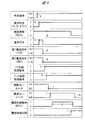
続いて、車両衝突からバッテリコントローラ16に履歴情報を記録するまでの手順をタイミングチャートに沿って説明する。図4は車両衝突から履歴情報が記録されるまでの手順を示すタイミングチャートである。図4に示すように、電動車両10が障害物等に衝突し(符号a)、エアバッグコントローラ23によって車両衝突であると判定されると(符号b)、エアバッグコントローラ23からバッテリコントローラ16に衝突信号が送信される(符号c)。また、第1電源信号(+B)および第2電源信号(IGN)が共に低電位信号となると(符号d,e)、ノア回路45から高電位信号が出力される(符号f)。そして、ノア回路45から高電位信号が出力され(符号f)、バッテリコントローラ16が衝突信号を受信し(符号c)、かつバッテリコントローラ16に履歴情報が記録されてない場合に(符号g)、アンド回路46から高電位信号が出力される(符号h)。 Next, the procedure from the vehicle collision until the history information is recorded in the
そして、アンド回路46から高電位信号が出力されると(符号h)、バッテリコントローラ16は、遮断リレーユニット29を開放状態に切り替え(符号i)、電源リレーユニット31を接続状態に切り替える(符号j)。すなわち、バッテリコントローラ16は、車両衝突に伴って低電圧バッテリ24が電源として機能しなくなる虞がある場合に、バッテリコントローラ16の電源を低電圧バッテリ24から高電圧バッテリ15に切り替えている。これにより、低電圧バッテリ24が電源として機能しない場合であっても、バッテリコントローラ16を正常に機能させることが可能となる。そして、バッテリコントローラ16は、履歴情報記録部30への書き込み動作を実行し(符号k)、履歴情報記録部30に車両衝突の履歴情報を記録する(符号l)。 When a high potential signal is output from the AND circuit 46 (reference symbol h), the
また、バッテリコントローラ16に対する履歴情報の記録が完了すると(符号l)、電源リレーユニット31が接続状態から開放状態に切り替えられる(符号m)。これにより、バッテリコントローラ16から高電圧バッテリ15を切り離すことができ、安全性を向上させることが可能となる。また、バッテリコントローラ16に対する電力供給が遮断されるため、高電圧バッテリ15の劣化を抑制することが可能となる。特に、電源リレーユニット31を接続状態に切り替えた場合には、高電圧バッテリ15を構成する一部のバッテリセル32c,32dが放電されるため、各バッテリセル32a〜32fの電圧にバラツキが生じることになる。すなわち、各バッテリセル32a〜32fの容量偏差が拡大することになるが、電源リレーユニット31を開放状態に切り替えることにより、容量偏差の拡大を抑制して高電圧バッテリ15の性能を維持することが可能となる。 Further, when the recording of the history information for the
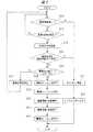
続いて、車両衝突からバッテリコントローラ16に履歴情報を記録するまでの手順をフローチャートに沿って説明する。図5は車両衝突から履歴情報が記録されるまでの手順を示すフローチャートである。図5に示すように、ステップS10では、バッテリコントローラ16に履歴情報が記録されているか否かが判定される。ステップS10において、車両衝突が発生していないにも拘わらず履歴情報が記録済であると判定された場合には、ステップS11に進み、高電圧バッテリ15のメインリレー14が開放状態に切り替えられ、ステップS12に進み、システムエラーが出力される。一方、ステップS10において、履歴情報が記録されていないと判定された場合には、ステップS13に進み、エアバッグコントローラ23から衝突信号を受信しているか否かが判定される。ステップS13において、衝突信号を受信していると判定された場合には、ステップS14に進み、バッテリコントローラ16に衝突信号が記録される。続くステップS15では、バッテリコントローラ16が規定回数以上の衝突信号を受信したか否かが判定される。ステップS15において、規定回数以上の衝突信号を受信していると判定された場合には、ステップS11に進み、高電圧バッテリ15のメインリレー14が開放状態に切り替えられ、ステップS12に進み、システムエラーが出力される。 Next, a procedure from the vehicle collision until the history information is recorded in the
また、ステップS15において、規定回数以上の衝突信号を受信していないと判定された場合には、ステップS16に進み、低電圧バッテリ24の出力が低下しているか否かが判定される。ステップS16において、低電圧バッテリ24の出力低下が認められない場合には、ステップS17に進み、バッテリコントローラ16から衝突信号が消去され、再びステップS10から各種条件が判定される。一方、ステップS16において、低電圧バッテリ24の出力低下が認められた場合には、ステップS18に進み、遮断リレーユニット29が開放状態に切り替えられ、ステップS19に進み、電源リレーユニット31が接続状態に切り替えられる。すなわち、バッテリコントローラ16は、車両衝突に伴って低電圧バッテリ24が電源として機能しなくなる虞がある場合に、バッテリコントローラ16の電源を低電圧バッテリ24から高電圧バッテリ15に切り替えている。これにより、低電圧バッテリ24が電源として機能しない場合であっても、バッテリコントローラ16を正常に機能させることが可能となる。 In Step S15, when it is determined that the collision signal is not received more than the specified number of times, the process proceeds to Step S16, and it is determined whether or not the output of the
次いで、ステップS20に進み、バッテリコントローラ16に対する車両衝突の履歴情報の記録が開始され、続くステップS21において、履歴情報の記録が完了すると、ステップS22に進み、電源リレーユニット31が接続状態から開放状態に切り替えられる。これにより、バッテリコントローラ16から高電圧バッテリ15を切り離すことができ、安全性を向上させることが可能となる。また、バッテリコントローラ16に対する電力供給が遮断されるため、高電圧バッテリ15の劣化を抑制することが可能となる。特に、電源リレーユニット31を接続状態に切り替えた場合には、高電圧バッテリ15を構成する一部のバッテリセル32c,32dが放電されるため、各バッテリセル32a〜32fの電圧にバラツキが生じることになる。すなわち、各バッテリセル32a〜32fの容量偏差が拡大することになるが、電源リレーユニット31を開放状態に切り替えることにより、容量偏差の拡大を抑制して高電圧バッテリ15の性能を維持することが可能となる。 Next, the process proceeds to step S20, where the recording of the vehicle collision history information with respect to the
本発明は前記実施の形態に限定されるものではなく、その要旨を逸脱しない範囲で種々変更可能であることはいうまでもない。本発明が適用される電動車両10としては、動力源として電動モータ12を備えた電気自動車であっても良く、動力源として電動モータ12およびエンジンを備えたハイブリッド自動車であっても良い。さらに、電動車両10としては、外部電源を用いた充電が可能な所謂プラグイン方式のハイブリッド自動車であっても良い。また、前述の説明では、低電圧バッテリ24の出力低下を判定するため、第1電源信号(+B)と第2電源信号(IGN)とを用いているが、これに限られることはなく、第1電源信号(+B)または第2電源信号(IGN)の一方だけを用いても良い。さらに、低電圧バッテリ24の電流値に基づいて、低電圧バッテリ24の出力低下を判定しても良い。 It goes without saying that the present invention is not limited to the above-described embodiment, and various modifications can be made without departing from the scope of the invention. The
前述の説明では、バッテリコントローラ16を、出力検出部、情報記録部および制御部として機能させているが、これに限られることはなく、他のコントローラを出力検出部、情報記録部あるいは制御部として機能させても良い。また、前述の説明では、エアバッグコントローラ23を衝突検出部として機能させているが、これに限られることはなく、他のコントローラを衝突検出部として機能させても良い。また、前述の説明では、回路開閉部として機能する電源リレーユニット31を半導体リレー33,34によって構成しているが、これに限られることはなく、電磁力によって駆動されるリレーやコンタクタ等を用いて電源リレーユニット31を構成しても良い。さらに、電源リレーユニット31は一対の半導体リレー33,34を備えているが、これに限られることはなく、1つの半導体リレーによって遮断リレーユニット29を構成しても良い。 In the above description, the
図4に示す場合には、遮断リレーユニット29を開放した後に電源リレーユニット31を接続しているが、これに限られることはなく、電源リレーユニット31を接続した後に遮断リレーユニット29を開放しても良い。また、同じタイミングで、遮断リレーユニット29を開放し、電源リレーユニット31を接続しても良い。なお、低電圧バッテリ24や高電圧バッテリ15としては、如何なる形式の蓄電体であっても良い。例えば、鉛バッテリ、ニッケル水素バッテリ、リチウムイオンバッテリ、電気二重層キャパシタ、リチウムイオンキャパシタ等を用いることが可能である。 In the case shown in FIG. 4, the power
10 電動車両
15 高電圧バッテリ(第2蓄電体)
16 バッテリコントローラ(出力検出部,情報記録部,制御部)
23 エアバッグコントローラ(衝突検出部)
24 低電圧バッテリ(第1蓄電体)
31 電源リレーユニット(回路開閉部)
32a〜32f バッテリセル(蓄電要素)10
16 Battery controller (output detection unit, information recording unit, control unit)
23 Airbag controller (collision detection unit)
24 Low voltage battery (first power storage unit)
31 Power relay unit (circuit open / close part)
32a to 32f battery cells (storage elements)
Claims (4)
Translated fromJapanese前記第1蓄電体の出力を検出する出力検出部と、
車両衝突を検出する衝突検出部と、
前記第1蓄電体が電源として接続され、前記衝突検出部からの衝突情報を記録する情報記録部と、
前記第2蓄電体と前記情報記録部との間に設けられ、前記第2蓄電体と前記情報記録部とを切り離す第1状態と、前記第2蓄電体と前記情報記録部とを接続する第2状態と、に切り替えられる回路開閉部と、
前記衝突検出部によって車両衝突が検出され、前記出力検出部によって前記第1蓄電体の出力低下が検出された場合に、前記回路開閉部を第1状態から第2状態に切り替える制御部と、
を有し、
前記衝突検出部によって車両衝突が検出され、前記出力検出部によって前記第1蓄電体の出力低下が検出された場合に、前記情報記録部は前記第2蓄電体を電源に用いて前記衝突検出部からの衝突情報を記録する、電動車両。An electric vehicle including a first power storage unit and a second power storage unit having a higher voltage than the first power storage unit,
An output detector for detecting an output of the first power storage unit;
A collision detection unit for detecting a vehicle collision;
An information recording unit configured to record collision information from the collision detection unit, wherein the first power storage unit is connected as a power source;
A first state that is provided between the second power storage unit and the information recording unit and that separates the second power storage unit and the information recording unit; and a second state that connects the second power storage unit and the information recording unit. A circuit opening and closing section that can be switched between two states;
A control unit that switches the circuit opening / closing unit from the first state to the second state when a vehicle collision is detected by the collision detection unit and a decrease in the output of the first power storage unit is detected by the output detection unit;
Have
When the collision detection unit detects a vehicle collision and the output detection unit detects a decrease in the output of the first power storage unit, the information recording unit uses the second power storage unit as a power source. An electric vehicle that records collision information from
前記第2蓄電体と前記情報記録部とは、一体に設けられる、電動車両。The electric vehicle according to claim 1,
The electric vehicle in which the second power storage unit and the information recording unit are provided integrally.
前記情報記録部が前記第2蓄電体を電源に用いて衝突情報を記録した後に、前記制御部は前記回路開閉部を第2状態から第1状態に切り替える、電動車両。The electric vehicle according to claim 1 or 2,
After the information recording unit records the collision information using the second power storage unit as a power source, the control unit switches the circuit opening / closing unit from the second state to the first state.
前記第2蓄電体は、直列接続される複数の蓄電要素を備え、
第2状態に切り替えられた前記回路開閉部は、前記複数の蓄電要素の一部と前記情報記録部とを接続する、電動車両。The electric vehicle according to any one of claims 1 to 3,
The second power storage unit includes a plurality of power storage elements connected in series,
The circuit opening and closing unit switched to the second state is an electric vehicle that connects a part of the plurality of power storage elements and the information recording unit.
Priority Applications (4)
| Application Number | Priority Date | Filing Date | Title |
|---|---|---|---|
| JP2013213707AJP5730975B2 (en) | 2013-10-11 | 2013-10-11 | Electric vehicle |
| US14/508,138US9623754B2 (en) | 2013-10-11 | 2014-10-07 | Electric vehicle |
| DE102014114682.4ADE102014114682B4 (en) | 2013-10-11 | 2014-10-09 | Electric vehicle with an information recording device |
| CN201410531747.XACN104553814B (en) | 2013-10-11 | 2014-10-10 | Electric vehicle |
Applications Claiming Priority (1)
| Application Number | Priority Date | Filing Date | Title |
|---|---|---|---|
| JP2013213707AJP5730975B2 (en) | 2013-10-11 | 2013-10-11 | Electric vehicle |
Publications (2)
| Publication Number | Publication Date |
|---|---|
| JP2015077042A JP2015077042A (en) | 2015-04-20 |
| JP5730975B2true JP5730975B2 (en) | 2015-06-10 |
Family
ID=52738172
Family Applications (1)
| Application Number | Title | Priority Date | Filing Date |
|---|---|---|---|
| JP2013213707AActiveJP5730975B2 (en) | 2013-10-11 | 2013-10-11 | Electric vehicle |
Country Status (4)
| Country | Link |
|---|---|
| US (1) | US9623754B2 (en) |
| JP (1) | JP5730975B2 (en) |
| CN (1) | CN104553814B (en) |
| DE (1) | DE102014114682B4 (en) |
Families Citing this family (22)
| Publication number | Priority date | Publication date | Assignee | Title |
|---|---|---|---|---|
| JP5776678B2 (en)* | 2012-12-21 | 2015-09-09 | トヨタ自動車株式会社 | Vehicle equipped with power control unit |
| CN106711519A (en)* | 2015-07-17 | 2017-05-24 | 北京理工大学 | Safety system of electric car battery unit structure, and control method thereof |
| US10086705B2 (en)* | 2016-06-28 | 2018-10-02 | Toyota Motor Engineering & Manufacturing North America, Inc. | Multipoint emergency responder safety isolation system |
| KR101686421B1 (en)* | 2016-07-27 | 2016-12-14 | 주식회사 아노마테크닉 | Car battery management system |
| DE102016117441A1 (en)* | 2016-09-16 | 2018-03-22 | Dr. Ing. H.C. F. Porsche Aktiengesellschaft | Traction battery and vehicle with such |
| DE102016222676A1 (en)* | 2016-11-17 | 2018-05-17 | Mahle International Gmbh | Electrical energy storage for a motor vehicle |
| DE102016224813A1 (en)* | 2016-12-13 | 2018-06-14 | Bayerische Motoren Werke Aktiengesellschaft | Motor vehicle with an electric motor, in particular hybrid or electric vehicle |
| JP6565940B2 (en)* | 2017-01-17 | 2019-08-28 | トヨタ自動車株式会社 | vehicle |
| AT519611B1 (en)* | 2017-02-13 | 2018-11-15 | Zkw Group Gmbh | Headlight for motor vehicles with at least one light source |
| JP6496342B2 (en)* | 2017-03-28 | 2019-04-03 | 株式会社Subaru | Vehicle control device |
| DE102017205861B3 (en) | 2017-04-06 | 2018-08-09 | Audi Ag | Safety device for reversibly switching off at least one electrical component of a motor vehicle, motor vehicle with a safety device and method for operating a safety device |
| KR102400470B1 (en)* | 2017-07-03 | 2022-05-20 | 현대자동차주식회사 | Vehicle and method for controlling thereof |
| CN107885132B (en)* | 2017-12-20 | 2024-02-13 | 北京强度环境研究所 | Low-power consumption long-endurance data recorder |
| CN108357444A (en)* | 2017-12-26 | 2018-08-03 | 惠州市德赛西威汽车电子股份有限公司 | Vehicle electronic device reserve battery state of emergency control switching circuit |
| JP6851105B2 (en)* | 2018-03-07 | 2021-03-31 | 株式会社ナイルワークス | Unmanned aerial vehicle, mobile |
| CN109050255B (en)* | 2018-07-09 | 2021-07-02 | 安徽安凯汽车股份有限公司 | Intelligent power-off low-voltage device of electric motor coach |
| JP7293599B2 (en)* | 2018-10-12 | 2023-06-20 | 株式会社Gsユアサ | How to reuse secondary batteries |
| KR102682084B1 (en)* | 2019-10-10 | 2024-07-08 | 현대자동차주식회사 | Vehicle and method of controlling the same |
| KR20220053762A (en)* | 2020-10-22 | 2022-05-02 | 현대자동차주식회사 | Apparatus for supporting safety of deiver and method thereof |
| CN112477605B (en)* | 2020-12-04 | 2022-04-08 | 浙江吉利控股集团有限公司 | A control method and control system for powering on and off a vehicle |
| CN114194029B (en)* | 2021-11-01 | 2024-01-09 | 岚图汽车科技有限公司 | Vehicle power supply system and vehicle |
| CN115257387A (en)* | 2022-08-31 | 2022-11-01 | 奇瑞汽车股份有限公司 | A high-voltage unloading protection method and device based on collision pre-judgment logic |
Family Cites Families (19)
| Publication number | Priority date | Publication date | Assignee | Title |
|---|---|---|---|---|
| JPH07274301A (en)* | 1994-03-24 | 1995-10-20 | Nissan Shatai Co Ltd | Power supply switcher for electric automobile |
| US6661116B1 (en)* | 2000-04-20 | 2003-12-09 | Mitsubishi Denki Kabushiki Kaisha | Battery switching device and emergency alerting system comprising this |
| JP4345948B2 (en)* | 2000-05-19 | 2009-10-14 | 本田技研工業株式会社 | Motorcycle accident notification system |
| US6630884B1 (en)* | 2000-06-12 | 2003-10-07 | Lucent Technologies Inc. | Surveillance system for vehicles that captures visual or audio data |
| JP2004320877A (en)* | 2003-04-15 | 2004-11-11 | Toyota Motor Corp | Power device for driving device, automobile equipped with the same, and control method for power device |
| JP2006050779A (en)* | 2004-08-04 | 2006-02-16 | Toyota Motor Corp | Motor driving device |
| JP4285550B2 (en)* | 2007-02-15 | 2009-06-24 | 株式会社デンソー | In-vehicle emergency call device |
| JP4245059B2 (en)* | 2007-02-27 | 2009-03-25 | 株式会社デンソー | In-vehicle emergency call device |
| US8239092B2 (en)* | 2007-05-08 | 2012-08-07 | Smartdrive Systems Inc. | Distributed vehicle event recorder systems having a portable memory data transfer system |
| JP5317188B2 (en)* | 2009-02-20 | 2013-10-16 | 株式会社安川電機 | Inverter device for electric vehicle and protection method thereof |
| JP2011155743A (en)* | 2010-01-26 | 2011-08-11 | Toyota Motor Corp | Electric vehicle |
| JP5671249B2 (en)* | 2010-03-31 | 2015-02-18 | 本田技研工業株式会社 | Electric car |
| IT1399313B1 (en)* | 2010-04-07 | 2013-04-16 | Ferrari Spa | ELECTRICAL SYSTEM OF A ROAD VEHICLE WITH ELECTRIC PROPULSION AND ITS CONTROL METHOD |
| JP2012061955A (en)* | 2010-09-16 | 2012-03-29 | Denso Corp | Power supply apparatus of control device for occupant protection device |
| JP2013062909A (en) | 2011-09-12 | 2013-04-04 | Toyota Motor Corp | Vehicle |
| JP5865013B2 (en)* | 2011-10-27 | 2016-02-17 | 三洋電機株式会社 | Power supply device for vehicle and vehicle provided with this power supply device |
| CN202480896U (en)* | 2012-01-13 | 2012-10-10 | 浙江吉利汽车研究院有限公司 | Safety redundancy device for automobile power battery system |
| US9263901B2 (en)* | 2012-05-19 | 2016-02-16 | Tesla Motors, Inc. | Secondary service port for high voltage battery packs |
| JP5776678B2 (en)* | 2012-12-21 | 2015-09-09 | トヨタ自動車株式会社 | Vehicle equipped with power control unit |
- 2013
- 2013-10-11JPJP2013213707Apatent/JP5730975B2/enactiveActive
- 2014
- 2014-10-07USUS14/508,138patent/US9623754B2/enactiveActive
- 2014-10-09DEDE102014114682.4Apatent/DE102014114682B4/enactiveActive
- 2014-10-10CNCN201410531747.XApatent/CN104553814B/enactiveActive
Also Published As
| Publication number | Publication date |
|---|---|
| CN104553814A (en) | 2015-04-29 |
| DE102014114682A1 (en) | 2015-04-16 |
| CN104553814B (en) | 2016-05-11 |
| DE102014114682B4 (en) | 2017-02-09 |
| US9623754B2 (en) | 2017-04-18 |
| US20150102666A1 (en) | 2015-04-16 |
| JP2015077042A (en) | 2015-04-20 |
Similar Documents
| Publication | Publication Date | Title |
|---|---|---|
| JP5730975B2 (en) | Electric vehicle | |
| US10230231B2 (en) | High voltage cutoff for electrified vehicles | |
| JP6793637B2 (en) | Battery management device and power supply system | |
| US10761530B2 (en) | Redundant low-voltage battery system operation in electric vehicles | |
| KR100921061B1 (en) | How to protect your battery in a hybrid vehicle | |
| US20180043779A1 (en) | Vehicle | |
| JP4238176B2 (en) | Electric vehicle | |
| CN202923410U (en) | High-voltage protection system of power battery and vehicle | |
| US10913408B2 (en) | System for determining state of power relay assembly | |
| JP2006062568A (en) | Car | |
| JP6972027B2 (en) | Management device and power storage system | |
| JP2014110683A (en) | Power storage system | |
| US9919604B2 (en) | Power net system of fuel cell vehicle and method for controlling the same | |
| JP5994652B2 (en) | Vehicle power supply control device | |
| CN107020964A (en) | Fuel cell system for vehicles and its control method | |
| JP2020099112A (en) | Precharge control device | |
| JP4529851B2 (en) | Power supply circuit abnormality detection device | |
| JP5167915B2 (en) | Auxiliary power supply system for electric power steering system | |
| US20150352957A1 (en) | Secondary Battery and Secondary Battery Module | |
| CN103770655A (en) | High-voltage protection system of power battery and vehicle | |
| JP6361491B2 (en) | Power control device | |
| KR101480649B1 (en) | Vehicular control system and its operating method | |
| US20250262958A1 (en) | Integrated isolation switch operation for ac and dc charging | |
| JP2021141780A (en) | Power supply control device and power supply control method | |
| WO2023145465A1 (en) | In-vehicle power supply system |
Legal Events
| Date | Code | Title | Description |
|---|---|---|---|
| TRDD | Decision of grant or rejection written | ||
| A01 | Written decision to grant a patent or to grant a registration (utility model) | Free format text:JAPANESE INTERMEDIATE CODE: A01 Effective date:20150407 | |
| A61 | First payment of annual fees (during grant procedure) | Free format text:JAPANESE INTERMEDIATE CODE: A61 Effective date:20150408 | |
| R150 | Certificate of patent or registration of utility model | Ref document number:5730975 Country of ref document:JP Free format text:JAPANESE INTERMEDIATE CODE: R150 | |
| S533 | Written request for registration of change of name | Free format text:JAPANESE INTERMEDIATE CODE: R313533 | |
| R350 | Written notification of registration of transfer | Free format text:JAPANESE INTERMEDIATE CODE: R350 | |
| R250 | Receipt of annual fees | Free format text:JAPANESE INTERMEDIATE CODE: R250 | |
| R250 | Receipt of annual fees | Free format text:JAPANESE INTERMEDIATE CODE: R250 | |
| R250 | Receipt of annual fees | Free format text:JAPANESE INTERMEDIATE CODE: R250 | |
| R250 | Receipt of annual fees | Free format text:JAPANESE INTERMEDIATE CODE: R250 | |
| R250 | Receipt of annual fees | Free format text:JAPANESE INTERMEDIATE CODE: R250 | |
| R250 | Receipt of annual fees | Free format text:JAPANESE INTERMEDIATE CODE: R250 | |
| R250 | Receipt of annual fees | Free format text:JAPANESE INTERMEDIATE CODE: R250 | |
| R250 | Receipt of annual fees | Free format text:JAPANESE INTERMEDIATE CODE: R250 |