JP5730873B2 - Deflectionable treatment instrument port - Google Patents
Deflectionable treatment instrument portDownload PDFInfo
- Publication number
- JP5730873B2 JP5730873B2JP2012523063AJP2012523063AJP5730873B2JP 5730873 B2JP5730873 B2JP 5730873B2JP 2012523063 AJP2012523063 AJP 2012523063AJP 2012523063 AJP2012523063 AJP 2012523063AJP 5730873 B2JP5730873 B2JP 5730873B2
- Authority
- JP
- Japan
- Prior art keywords
- treatment instrument
- port
- actuator
- treatment
- distal end
- Prior art date
- Legal status (The legal status is an assumption and is not a legal conclusion. Google has not performed a legal analysis and makes no representation as to the accuracy of the status listed.)
- Active
Links
- 238000000034methodMethods0.000claimsdescription12
- 230000000087stabilizing effectEffects0.000claimsdescription12
- 239000004606Fillers/ExtendersSubstances0.000claimsdescription3
- 230000008859changeEffects0.000claimsdescription3
- 230000000392somatic effectEffects0.000claims1
- 238000012546transferMethods0.000description60
- 238000001356surgical procedureMethods0.000description17
- 230000003014reinforcing effectEffects0.000description10
- 239000000463materialSubstances0.000description8
- 230000006641stabilisationEffects0.000description7
- 238000011105stabilizationMethods0.000description7
- 238000007789sealingMethods0.000description5
- 229920001169thermoplasticPolymers0.000description5
- 239000004416thermosoftening plasticSubstances0.000description5
- 210000001519tissueAnatomy0.000description5
- HGAZMNJKRQFZKS-UHFFFAOYSA-Nchloroethene;ethenyl acetateChemical compoundClC=C.CC(=O)OC=CHGAZMNJKRQFZKS-UHFFFAOYSA-N0.000description4
- 230000006835compressionEffects0.000description4
- 238000007906compressionMethods0.000description4
- 230000008878couplingEffects0.000description4
- 238000010168coupling processMethods0.000description4
- 238000005859coupling reactionMethods0.000description4
- 229910001220stainless steelInorganic materials0.000description4
- 239000010935stainless steelSubstances0.000description4
- 238000005452bendingMethods0.000description3
- 230000002496gastric effectEffects0.000description3
- 238000002357laparoscopic surgeryMethods0.000description3
- 230000007246mechanismEffects0.000description3
- 229920005992thermoplastic resinPolymers0.000description3
- 241001631457CannulaSpecies0.000description2
- 238000001574biopsyMethods0.000description2
- 238000013461designMethods0.000description2
- 238000003780insertionMethods0.000description2
- 230000037431insertionEffects0.000description2
- 210000001503jointAnatomy0.000description2
- 238000002324minimally invasive surgeryMethods0.000description2
- 210000003200peritoneal cavityAnatomy0.000description2
- 239000004810polytetrafluoroethyleneSubstances0.000description2
- 229920001343polytetrafluoroethylenePolymers0.000description2
- 239000012779reinforcing materialSubstances0.000description2
- 210000002784stomachAnatomy0.000description2
- 241000239290AraneaeSpecies0.000description1
- 208000008589ObesityDiseases0.000description1
- 208000037062PolypsDiseases0.000description1
- 210000001015abdomenAnatomy0.000description1
- 210000000683abdominal cavityAnatomy0.000description1
- 230000008901benefitEffects0.000description1
- 230000001413cellular effectEffects0.000description1
- 239000002131composite materialSubstances0.000description1
- 238000002788crimpingMethods0.000description1
- 230000003247decreasing effectEffects0.000description1
- 238000003745diagnosisMethods0.000description1
- 210000002310elbow jointAnatomy0.000description1
- 238000005516engineering processMethods0.000description1
- 239000012530fluidSubstances0.000description1
- 239000007943implantSubstances0.000description1
- 238000002513implantationMethods0.000description1
- 238000007373indentationMethods0.000description1
- 238000002347injectionMethods0.000description1
- 239000007924injectionSubstances0.000description1
- 230000002262irrigationEffects0.000description1
- 238000003973irrigationMethods0.000description1
- 230000001050lubricating effectEffects0.000description1
- 230000004048modificationEffects0.000description1
- 238000012986modificationMethods0.000description1
- 230000003387muscularEffects0.000description1
- 235000020824obesityNutrition0.000description1
- 210000004303peritoneumAnatomy0.000description1
- 230000004044responseEffects0.000description1
- 230000035945sensitivityEffects0.000description1
- 238000012800visualizationMethods0.000description1
Images


Classifications
- A—HUMAN NECESSITIES
- A61—MEDICAL OR VETERINARY SCIENCE; HYGIENE
- A61B—DIAGNOSIS; SURGERY; IDENTIFICATION
- A61B17/00—Surgical instruments, devices or methods
- A61B17/34—Trocars; Puncturing needles
- A61B17/3417—Details of tips or shafts, e.g. grooves, expandable, bendable; Multiple coaxial sliding cannulas, e.g. for dilating
- A61B17/3421—Cannulas
- A—HUMAN NECESSITIES
- A61—MEDICAL OR VETERINARY SCIENCE; HYGIENE
- A61B—DIAGNOSIS; SURGERY; IDENTIFICATION
- A61B1/00—Instruments for performing medical examinations of the interior of cavities or tubes of the body by visual or photographical inspection, e.g. endoscopes; Illuminating arrangements therefor
- A61B1/04—Instruments for performing medical examinations of the interior of cavities or tubes of the body by visual or photographical inspection, e.g. endoscopes; Illuminating arrangements therefor combined with photographic or television appliances
- A61B1/05—Instruments for performing medical examinations of the interior of cavities or tubes of the body by visual or photographical inspection, e.g. endoscopes; Illuminating arrangements therefor combined with photographic or television appliances characterised by the image sensor, e.g. camera, being in the distal end portion
- A61B1/051—Details of CCD assembly
- A—HUMAN NECESSITIES
- A61—MEDICAL OR VETERINARY SCIENCE; HYGIENE
- A61B—DIAGNOSIS; SURGERY; IDENTIFICATION
- A61B17/00—Surgical instruments, devices or methods
- A61B17/34—Trocars; Puncturing needles
- A61B17/3417—Details of tips or shafts, e.g. grooves, expandable, bendable; Multiple coaxial sliding cannulas, e.g. for dilating
- A61B17/3421—Cannulas
- A61B17/3423—Access ports, e.g. toroid shape introducers for instruments or hands
- A—HUMAN NECESSITIES
- A61—MEDICAL OR VETERINARY SCIENCE; HYGIENE
- A61B—DIAGNOSIS; SURGERY; IDENTIFICATION
- A61B17/00—Surgical instruments, devices or methods
- A61B17/34—Trocars; Puncturing needles
- A61B17/3462—Trocars; Puncturing needles with means for changing the diameter or the orientation of the entrance port of the cannula, e.g. for use with different-sized instruments, reduction ports, adapter seals
- A—HUMAN NECESSITIES
- A61—MEDICAL OR VETERINARY SCIENCE; HYGIENE
- A61B—DIAGNOSIS; SURGERY; IDENTIFICATION
- A61B18/00—Surgical instruments, devices or methods for transferring non-mechanical forms of energy to or from the body
- A61B18/04—Surgical instruments, devices or methods for transferring non-mechanical forms of energy to or from the body by heating
- A61B18/12—Surgical instruments, devices or methods for transferring non-mechanical forms of energy to or from the body by heating by passing a current through the tissue to be heated, e.g. high-frequency current
- A61B18/14—Probes or electrodes therefor
- A61B18/1492—Probes or electrodes therefor having a flexible, catheter-like structure, e.g. for heart ablation
- A—HUMAN NECESSITIES
- A61—MEDICAL OR VETERINARY SCIENCE; HYGIENE
- A61B—DIAGNOSIS; SURGERY; IDENTIFICATION
- A61B90/00—Instruments, implements or accessories specially adapted for surgery or diagnosis and not covered by any of the groups A61B1/00 - A61B50/00, e.g. for luxation treatment or for protecting wound edges
- A61B90/50—Supports for surgical instruments, e.g. articulated arms
- A61B90/57—Accessory clamps
- A—HUMAN NECESSITIES
- A61—MEDICAL OR VETERINARY SCIENCE; HYGIENE
- A61M—DEVICES FOR INTRODUCING MEDIA INTO, OR ONTO, THE BODY; DEVICES FOR TRANSDUCING BODY MEDIA OR FOR TAKING MEDIA FROM THE BODY; DEVICES FOR PRODUCING OR ENDING SLEEP OR STUPOR
- A61M16/00—Devices for influencing the respiratory system of patients by gas treatment, e.g. ventilators; Tracheal tubes
- A61M16/04—Tracheal tubes
- A61M16/0463—Tracheal tubes combined with suction tubes, catheters or the like; Outside connections
- A—HUMAN NECESSITIES
- A61—MEDICAL OR VETERINARY SCIENCE; HYGIENE
- A61B—DIAGNOSIS; SURGERY; IDENTIFICATION
- A61B17/00—Surgical instruments, devices or methods
- A61B17/00234—Surgical instruments, devices or methods for minimally invasive surgery
- A61B2017/00292—Surgical instruments, devices or methods for minimally invasive surgery mounted on or guided by flexible, e.g. catheter-like, means
- A61B2017/003—Steerable
- A61B2017/00318—Steering mechanisms
- A—HUMAN NECESSITIES
- A61—MEDICAL OR VETERINARY SCIENCE; HYGIENE
- A61B—DIAGNOSIS; SURGERY; IDENTIFICATION
- A61B17/00—Surgical instruments, devices or methods
- A61B17/28—Surgical forceps
- A61B17/29—Forceps for use in minimally invasive surgery
- A61B2017/2901—Details of shaft
- A61B2017/2908—Multiple segments connected by articulations
- A—HUMAN NECESSITIES
- A61—MEDICAL OR VETERINARY SCIENCE; HYGIENE
- A61B—DIAGNOSIS; SURGERY; IDENTIFICATION
- A61B17/00—Surgical instruments, devices or methods
- A61B17/34—Trocars; Puncturing needles
- A61B17/3417—Details of tips or shafts, e.g. grooves, expandable, bendable; Multiple coaxial sliding cannulas, e.g. for dilating
- A61B17/3421—Cannulas
- A61B2017/3445—Cannulas used as instrument channel for multiple instruments
- A61B2017/3447—Linked multiple cannulas
- A—HUMAN NECESSITIES
- A61—MEDICAL OR VETERINARY SCIENCE; HYGIENE
- A61B—DIAGNOSIS; SURGERY; IDENTIFICATION
- A61B90/00—Instruments, implements or accessories specially adapted for surgery or diagnosis and not covered by any of the groups A61B1/00 - A61B50/00, e.g. for luxation treatment or for protecting wound edges
- A61B90/50—Supports for surgical instruments, e.g. articulated arms
- A61B2090/508—Supports for surgical instruments, e.g. articulated arms with releasable brake mechanisms
Landscapes
- Health & Medical Sciences (AREA)
- Life Sciences & Earth Sciences (AREA)
- Surgery (AREA)
- Engineering & Computer Science (AREA)
- Biomedical Technology (AREA)
- Heart & Thoracic Surgery (AREA)
- Animal Behavior & Ethology (AREA)
- General Health & Medical Sciences (AREA)
- Public Health (AREA)
- Veterinary Medicine (AREA)
- Nuclear Medicine, Radiotherapy & Molecular Imaging (AREA)
- Medical Informatics (AREA)
- Molecular Biology (AREA)
- Pathology (AREA)
- Oral & Maxillofacial Surgery (AREA)
- Physics & Mathematics (AREA)
- Pulmonology (AREA)
- Optics & Photonics (AREA)
- Hematology (AREA)
- Anesthesiology (AREA)
- Biophysics (AREA)
- Emergency Medicine (AREA)
- Radiology & Medical Imaging (AREA)
- Cardiology (AREA)
- Plasma & Fusion (AREA)
- Otolaryngology (AREA)
- Surgical Instruments (AREA)
- Endoscopes (AREA)
Description
Translated fromJapanese 発明者:
Brett Page
Salvatore Castro
本出願は、2009年7月29日に出願した米国仮出願No.61/229,275および2010年2月22日に出願した米国仮出願No.61/323,863の利益を享受することを要求するものであり、ここで参照することにより、これらの仮出願は本明細書に取り入れられるものである。 また、本出願は2009年7月28日に出願された米国出願No.12/511,043の一部継続出願として出願されたものである。Inventor:
Brett Page
Salvatore Castro
This application requires that you benefit from US Provisional Application No. 61 / 229,275 filed on July 29, 2009 and US Provisional Application No. 61 / 323,863 filed on February 22, 2010. Yes, and by reference here, these provisional applications are incorporated herein. This application was filed as a continuation-in-part of US Application No. 12 / 511,043 filed on July 28, 2009.
本発明は、体腔の中に、フレキシブルな医療器具を導入し、これを操縦したり偏向させたりするためのアクセス装置(アクセスシステムとも呼ぶ)およびポート部の技術分野に関するものである。 The present invention relates to a technical field of an access device (also referred to as an access system) and a port portion for introducing a flexible medical device into a body cavity and steering and deflecting the same.
腹腔内における外科手術として、腹腔鏡を使った手術がよく行われる。 この腹腔鏡手術では、手術を行うために必要な種々の処置器具や内視鏡を使って腹膜のある場所までアクセスするために、複数の小さい切開部や、トロカール用の孔や、ポート部が皮膚および皮膚下の筋肉部分、並びに腹膜細胞組織に設けられる。 腹膜腔を広げ、視認性を向上させ作業スペースを確保するため、膨張ガスを使用して腹膜腔を膨張させる方法が良く利用される。 そして、改良が加えられ、1箇所のポート部のみを使ってかかる手術を行うことができるようになってきている。 As a surgical operation in the abdominal cavity, a surgery using a laparoscope is often performed. In this laparoscopic surgery, a number of small incisions, trocar holes, and ports are used to access the place where the peritoneum is located using various treatment instruments and endoscopes necessary for the operation. It is provided in the skin and the muscular part under the skin, and peritoneal cell tissue. In order to widen the peritoneal cavity, improve visibility and secure a working space, a method of inflating the peritoneal cavity using inflation gas is often used. Improvements have been made and it is now possible to perform such surgery using only one port.
1箇所のポート部を使った手術(Single Port Surgery:SPSとも呼ぶ)においては、膨張ガスの圧力損失を生じることなく、手術空間にシーリングを維持したままアクセスできるように、切開部内に装置を配置することが望ましい。 理想的には、そのような装置があれば、複数の処置器具を同時に使用する際に処置器具間の干渉を避けながら複数の処置器具を、シーリングを維持したままアクセスさせることができる。
このようなSPSの手術やその他の腹腔鏡手術において使用することが望ましい、複数の処置器具のアクセス装置については、同時係属の以下の出願に記載されている。 すなわち、2007年5月17日出願の米国出願No.11/804,063(以下「'063出願」と呼ぶ)「発明の名称: 1箇所のアクセス用ポート部を使い複数の処置器具をアクセスさせるためのシステムおよび方法」、2008年9月12日出願の米国出願No.12/209,408「発明の名称:複数の処置器具のアクセス装置およびシステム」、2009年7月28日出願の米国出願No.12/511,043「発明の名称:複数の処置器具のアクセス装置およびシステム」、および2009年12月29日出願の米国出願No.12/649,307「発明の名称:最小の侵襲的外科手術のためのアクティブな処置器具用ポート部システム」である。 そして、これらはここで参照することにより、本明細書に組み入れられるものである。 前述の特許出願は、偏向可能な先端部を有する処置器具移送チューブを備えたアクセス装置またはアクセス・システムを開示するものである。 処置器具移送チューブを通過したフレキシブルな処置器具は、偏向可能な処置器具移送チューブを能動的に偏向させることによって操縦されるようになっている。 本明細書は、このような目的のために使用することができる処置器具移送チューブ、あるいは、当業者にとって周知であってその他の、単一または複数の処置器具用トロカールや、アクセス用ポート部や、血管内へのアクセス・システムと一緒に使用することができる処置器具移送チューブを開示するものである。In surgery using a single port part (also called SPS), the device is placed in the incision so that the surgical space can be accessed while maintaining the sealing without causing pressure loss of the inflation gas. It is desirable to do. Ideally, such a device would allow multiple treatment instruments to be accessed while maintaining sealing while avoiding interference between treatment instruments when using multiple treatment instruments simultaneously.
A plurality of treatment instrument access devices desirable for use in such SPS and other laparoscopic procedures are described in the following co-pending applications. That is, US application No. 11 / 804,063 filed on May 17, 2007 (hereinafter referred to as “'063 application”) “Title of Invention: Accessing multiple treatment instruments using one access port part” System and Method ", U.S. Application No. 12 / 209,408, filed September 12, 2008," Title of Invention: Access Device and System for Multiple Treatment Instruments ", U.S. Application No. 12 / filed on July 28, 2009. 511,043 “Title of Invention: Access Devices and Systems for Multiple Treatment Instruments” and US Application No. 12 / 649,307 filed December 29, 2009 “Title of Invention: Active Treatment for Minimally Invasive Surgery” The instrument port section system. These are hereby incorporated by reference herein. The aforementioned patent application discloses an access device or access system comprising a treatment instrument transfer tube having a deflectable tip. A flexible treatment instrument that has passed through the treatment instrument transfer tube is steered by actively deflecting the deflectable treatment instrument transfer tube. This specification describes a treatment instrument transfer tube that can be used for such purposes, or other single or multiple treatment instrument trocars, access port portions, etc. well known to those skilled in the art. A treatment instrument transfer tube that can be used with an intravascular access system is disclosed.
以下に説明する実施例は、フレキシブルな医療用処置器具を人体内へ入れるためのものであって、偏向可能で、好ましくはシーリングされた導管として機能する処置器具用ポート部に関するものである。 以下の説明から理解できるように、ポート部は体外に配置されたアクチュエータであって、ポート部の先端部をアクティブに偏向させることができるアクチュエータを含んでいる。 従って、ポート部を通って配置された処置器具の先端部もアクティブに偏向させることができる。 ここで説明する偏向可能なポート部は、体腔内へアクセスするために使用するのに適した種々のアクセス装置を通して体内まで伸びている。 そしてこのようなアクセス装置には、腹腔鏡用ポート部、トロカール、カニューレ、シール、複数処置器具のアクセス装置などが含まれるが、前記ポート部は、切開部を通して直接体内へ伸びるように配置することもできる。 The embodiment described below relates to a port for a treatment instrument for placing a flexible medical treatment instrument into the human body, which is deflectable and preferably functions as a sealed conduit. As can be understood from the following description, the port portion is an actuator arranged outside the body, and includes an actuator that can actively deflect the distal end portion of the port portion. Accordingly, the distal end portion of the treatment instrument disposed through the port portion can also be actively deflected. The deflectable port portion described herein extends into the body through various access devices suitable for use in accessing a body cavity. Such access devices include laparoscopic port parts, trocars, cannulas, seals, multi-treatment instrument access devices, etc., but the port parts should be arranged to extend directly into the body through the incision. You can also.
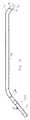
図1には、2つの偏向可能な処置器具用アクセス・ポート10が示されている。 このアクセス・ポートの各々は、細長い処置器具移送チューブ16を備えている。 図示する実施例では、図2に示すように、処置器具移送チューブ16はフレキシブルな先端部20を備えている。 アクセス・ポート10の基端部に配置されたアクチュエータ22は、処置器具移送チューブ16の内部に配置された処置器具の作動端部を操作するために、処置器具移送チューブ16のフレキシブルな先端部20の偏向量を制御するようになっている。 後で詳細に説明するように、アクセス・ポート10を経由して体腔内に展開する処置器具の先端部は、アクチュエータ22に設けられたコントロール・チューブ24の中に挿入される。 そして、処置器具の先端部は、処置器具移送チューブ16を通って前方へ進められる。 処置器具の基端側ハンドルを操作すると、それに合わせてコントロール・チューブ24が動くようになっており、その結果、処置器具移送チューブ16と処置器具の先端部が偏向するようになっている。 In FIG. 1, two deflectable treatment
処置器具移送チューブ16の特徴点については、図2に基づき説明する。 図示された実施例では、処置器具移送チューブ16は、ステンレス鋼またはその他のリジッドな管によって形成されたリジッドなチューブ18を備えている。 リジッドなチューブ18は、単一の管であっても良いし、互いに連結した複数の管から構成するようにしても良い。 図2に示すように、リジッドなチューブ18は、一般的にストレートのメイン部分70と先端領域66から成る固定された形状に賦形されて作られている。 そして、先端領域66には、曲部又は傾斜部68を作りだすために屈曲する部分が設けられている。 曲部又は傾斜部68における屈曲する部分の曲線は連続的なものであっても良いし、複数の部分から構成したものであっても良いし、同一の面内に配置するように形成しても良いし、複数の面内に亘って配置するように形成しても良い。 Features of the treatment
図2に示す曲部又は傾斜部68は、細長いS字形状をしており、その基端側は、メイン部分70の長手方向軸に対し、下方に向かって曲がっている。 そして、曲部又は傾斜部68の先端側は、わずかに上方に向かって曲がっている。 ここで、「上方」、「下方」という用語は図面を基準として表現したものであって、体腔の内側や外側にある特定の構造物を意味するものではない。 先端領域66には、曲部又は傾斜部68の先端側に第2のストレート部分72を追加的に設けるようにしても良い。 ここで、第2のストレート部分72の長手方向軸はストレートのメイン部分70の長手方向軸に平行になるように示されているが、ストレートのメイン部分70側に近づくようにしたり、あるいは離れるようにしたりすることもできる。 The curved portion or inclined portion 68 shown in FIG. 2 has an elongated S-shape, and the base end side is bent downward with respect to the longitudinal axis of the main portion 70. The leading end side of the curved portion or inclined portion 68 is slightly bent upward. Here, the terms “upper” and “lower” are expressed with reference to the drawings, and do not mean a specific structure inside or outside the body cavity. In the distal end region 66, a second straight portion 72 may be additionally provided on the distal end side of the curved portion or the inclined portion 68. Here, the longitudinal axis of the second straight portion 72 is shown to be parallel to the longitudinal axis of the straight main portion 70, but it may be closer to or away from the straight main portion 70 side. It can also be made.
図2に示す処置器具移送チューブ16では、ストレートのシャフト70(メイン部分70)、曲部又は傾斜部68、および先端部にある第2のストレート部分72は1つの平面内に存在している一方、リジッドなチューブ18の基端側曲部74は、下方へ曲がると共に、当該平面から曲がって外れている。 このような構成にすることによって、隣接する処置器具アクセス装置10(アクセス・ポート10)のコントロール・チューブ24が互いに広がるように配置することができるようになる。 その結果、隣接する処置器具アクセス装置10のコントロール・チューブ24同士の干渉を避けることができる。 図示した実施例に示すものとは異なった別の形状を有するリジッドなチューブ18を使用することもできる。 例えば、図3に示す別の形態の処置器具移送チューブでは、曲部は、S字形状を形成するのではなく、ストレートのシャフト70(メイン部分70)から伸びた単一の曲部又は傾斜部を有する1つの部分68aを形成している。 In the treatment
また、処置器具移送チューブ16は、リジッドなチューブ18の中を通って伸びているフレキシブルな内側チューブ20(先端部20)を更に備えている。 フレキシブルな内側チューブ20(先端部20)は、対応するリジッドなチューブ18の先端部と基端部のそれぞれから伸び出た先端部76と基端部78を備えている。 フレキシブルな内側チューブ20は、予め曲部又は傾斜部を成形しておくこともできるし、予成形しないようにすることもできる。 The treatment
フレキシブルな内側チューブ20は、体内で使用する処置器具を受け入れるための管腔を更に備えている。 複数のアクチュエーション・エレメント80(本明細書では、引張ワイヤーや引張ケーブルとして言及するが、別の形態のものであっても良い)は、内側チューブ20の壁面内に配置された引張ワイヤ用管腔(図示せず)の中を通って伸びると共に、先端部近傍において固定されている。 好ましい実施例では、処置器具移送チューブ16には、このような4本のワイヤが90度間隔で配置されている。 これとは別の実施例では、内側チューブ20の周りに等間隔に配置された3つの引張ワイヤのように、異なった数の引張ワイヤを使用することもできる。 The flexible
後で詳細に説明するように、引張ワイヤ80(アクチュエーション・エレメント80)はアクチュエータ22(図1参照)に連結されており、アクチュエータ22はフレキシブルな内側チューブ20の先端部76を偏向させるように引張ワイヤを操作するようになっている。 従って、フレキシブルな内側チューブ20は、処置器具を操作するために必要となる偏向を可能とするのに十分な柔軟性を有すると共に、好ましくは、よじれに対する抵抗力を備えるように構成されている。 ある実施例では、フレキシブルな内側チューブ20は、その管腔のライニングとしてのPFTE製内側ライナーと、ライナーを覆った熱可塑性樹脂シース(シースを通して形成された引張ワイヤ用の管腔を備えている)と、熱可塑性樹脂シースの外側に配置された強化層(メッシュまたはブレード(編組))と、強化層の外側に配置された第2の熱可塑性樹脂シースと、を使用した複合チューブとして構成されている。 これとは別の実施例では、第2の熱可塑性樹脂シースがなく、強化層がシースの外側層として機能するようにしている。 更に別の実施例では、強化層が、内側チューブ20の最も内側の層を形成するようになっている。 強化層の無い内側チューブ20や、強化材として機能する材料やその他の材料からなる層を追加した内側チューブ20を使用することもできる。 As will be described in detail later, the pull wire 80 (actuation element 80) is connected to the actuator 22 (see FIG. 1) so that the
ここで、リジッドなチューブ18はフレキシブルな内側チューブ20(従って、フレキシブルな内側チューブ20を通って配置される処置器具)を体腔内に保持するのに有用であるが、リジッドなチューブ18を使用しない、すなわち、処置器具移送チューブを備えたフレキシブルな内側チューブ20だけからなる、別の形態の実施例も可能であることに留意が必要である。 処置器具アクセス装置10(アクセス・ポート10)が、別のエレメントを使用して処置器具移送チューブ16のシャフトを保持する要素を備えた別のアクセス・ポートで使用されるような場合には、上述したような実施例も有用になる。 このような場合、体腔内にフレキシブルな内側チューブ20を保持するためにリジッドなチューブ18を使用する必要性が低下する。Here, the
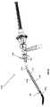
図4は、処置器具移送チューブ16の基端側端部とアクチュエータ組立22の断面図を示したものである。 一般に、アクチュエータ組立22は、先端側エレメント82と、基端側エレメント94と、先端側エレメント82と基端側エレメント94の間に伸びて配置されたスプリング96を備えている。 リジッドなコントロール・チューブ24は、基端側エレメント94に結合されている。 コントロール・チューブ24は、対応する処置器具移送チューブ16を通って体内で展開される医療用処置器具を受け入れるための管腔を備えている。 コントロール・チューブ24の中へ処置器具を容易に挿入できるようにするために、コントロール・チューブ24には、PTFEまたはその他の適切な材料で形成された潤滑性ライニングを備えるようにしても良い。 FIG. 4 shows a cross-sectional view of the proximal end of the treatment
先端側エレメント82は、処置器具移送チューブ16のリジッドなチューブ18の基端側端部に取り付けられている。 先端側エレメント82には、図6Aに関連して後で説明するように、処置器具アクセス装置10(アクセス・ポート10)を、更に大きなアクセス・システムに結合することができるようにするための部材36を備えるようにすることもできる。 The
先端側エレメント82には、管腔83が備えられている。 リジッドなチューブ18の基端側端部は、管腔83内の固定位置に配置されており、フレキシブルな内側チューブ20の基端側端部78は管腔83の中を更に基端側に伸びている。 複数の開口部又はスロット84(図4では1箇所のみ表示してある)が、先端側エレメント82の中に形成されている。 開口部又はスロット84の各々は、管腔83から先端側エレメント82の外側へ向かって伸びている。 The
先端側エレメント82の基端側部分では、管腔83は内側円筒状壁86によって取り囲まれており、内側円筒状壁86は、外側円筒状壁88によって取り囲まれている。 外側円筒状壁88は、基端側に面する円筒状内面又はレセプタクルを画成すると共に、内側円筒状壁86と外側円筒状壁88の間に円筒状の間隙92を形成する。 図1を見れば良く分かるように、複数の貫通孔90が円筒状の間隙92(図4参照)の基端側端部から基端側フィッティング82の外部に向かって伸びている。 貫通孔90と開口部又はスロット84は、半径方向位置が整合しており、それらの数は、対応する処置器具移送チューブ16内の引張ワイヤの数に一致している。 In the proximal end portion of the
再び図4を参照すると、基端側エレメント94は、先端側に面する円筒状内面又はレセプタクル108を形成する壁106を備えている。 管腔110は、円筒状内面又はレセプタクル108から基端側エレメント94の基端側面に向かって伸びている。 複数の引張ワイヤ用管腔112は、基端側エレメント94を通り、好ましくは管腔110に平行に伸びている。 Referring again to FIG. 4, the proximal element 94 includes a wall 106 forming a cylindrical inner surface or receptacle 108 facing the distal side. The lumen 110 extends from the cylindrical inner surface or receptacle 108 toward the proximal side surface of the proximal element 94. A plurality of puller wire lumens 112 extend through the proximal element 94 and preferably extend parallel to the lumen 110.
スプリング96は、基端側エレメント94と先端側エレメント82の間に結合されている。 図示する実施例では、スプリング96の先端側端部は、先端側エレメント82の外側円筒状壁88によって形成される基端側に面する円筒状内面又はレセプタクルの中に配置され、スプリング96の基端側端部は、基端側エレメント94の先端側に面する円筒状内面又はレセプタクル108の中に配置される。 The spring 96 is coupled between the proximal element 94 and the
スプリング96は、ステンレス鋼またはその他の適切な材料によって形成されたリジッドなスプリングである。 スプリング96の中を通って伸びるコンポーネントは、基端側エレメント94と先端側エレメント82の間のシールされた処置器具通路を形成する。 図4に示されたクロス-スリット・シール100のようなシールが、管腔83の中に配置されている。 このシールは、対応する処置器具移送チューブ16の中に処置器具が配置されていない間、アクチュエータ組立22を通じて送気圧が損失するのを防止する。
Tygon(登録商標) チューブ102のようなフレキシブルなチューブは、シール94から基端側へ伸びている。 コネクター104が内側円筒状壁86とTygon チューブ102を結合させ、シールを構成するようになっている。Spring 96 is a rigid spring formed of stainless steel or other suitable material. Components extending through the spring 96 form a sealed treatment instrument passage between the proximal element 94 and the
A flexible tube, such as the Tygon® tube 102, extends proximally from the seal 94. A connector 104 joins the inner cylindrical wall 86 and the Tygon tube 102 to form a seal.
Tygon チューブ102の基端側端部は、基端側エレメント94の管腔110の中へ伸びている。 管状カップリング114は、Tygon チューブ102とコントロール・チューブ24の間のシールされた結合部を形成し、コントロール・チューブ24は管腔110の中に配置された先端端部を備えている。 シール116がコントロール・チューブ24の基端側端部に配置されている。 シール116は、好ましくは、コントロール・チューブ24を通って配置された処置器具のシャフトに対する、シールに比例した開口部を有するエラストマー製隔膜タイプのシールである。The proximal end of the Tygon tube 102 extends into the lumen 110 of the proximal element 94. Tubular coupling 114 forms a sealed connection between Tygon tube 102 and
アクチュエータ組立22が、対応する処置器具移送チューブ16のフレキシブルな先端領域の偏向量を制御する機構について以下に説明する。 図2に関連して説明したように、引張ワイヤ(アクチュエーション・エレメント)80は、フレキシブルな内側チューブ20の各々の偏向可能な先端部分76の中に固定されており、フレキシブルな内側チューブ20の後端部分78から伸びて出ている。 そして、図3についての説明の中で述べたように、フレキシブルな内側チューブ20の後端部分78はアクチュエータ組立22の先端側エレメント82の中に配置されている。 それから、引張ワイヤ80は、先端側エレメント82から伸び、基端側エレメント94に固定されている。 ここで説明したものとは異なった構成とすることもできるが、ここで図示するものでは、引張ワイヤ80はフレキシブルな内側チューブ20から伸び、開口部又はスロット84を経由して先端側エレメント82から外へ出て、貫通孔90を経由して先端側エレメント82の中へ再び入り、スプリング96の中を通って基端側エレメント94の中へ伸びるようになっている。 引張ワイヤ80は、基端側エレメント94のところで調整ネジ118に結合されている。 調整ネジ118は、引張ワイヤ80の張力を増減させることによってアクチュエータ組立22の感度を調整するために、回転可能となっている。 A mechanism in which the
アクセス・ポート10を使用するために、皮膚および皮膚下にある細胞組織を通して切開部が形成される。 処置器具移送チューブ16の先端側端部はこの切開部を通して体腔の中へ挿入される。 アクチュエータ組立22は、体外に残ったままとなる。 偏向可能なアクセス・ポート10は個別に体内へ導入されるか、あるいは大きなアクセス・システムの一部として体内へ導入される。 そして、この大きなアクセス・システムは、切開部に着座したアクセス装置を備え、大きなアクセス・システムを通じてアクセス・ポート10が体内へと伸びるようになっている。 例えば、2008年9月12日に出願された米国特許出願No.12/209,408および2009年7月28日に出願された米国特許出願No.12/511,043において開示されているタイプの複数処置器具のアクセス・システムは切開部に配置され、1または複数のアクセス・ポート10用としてのアクセス・ポイントを提供するために使用されている。 図6Aおよび6Bに示す、そのようなアクセス・システム101の一つでは、追加的な処置器具を受け入れるための追加的なアクセス・ポート26、28(この例では、受動的なポートである)と一緒に、2つの偏向可能なアクセス・ポート10が使用されている。 外科医は、体腔内で手術を行うために必要な処置器具を選択するようになっている。 例えば、一対の偏向可能なアクセス・ポート10を示した図6Aを参照して説明すると、アクセス・ポート10の内の第1のポートを通して展開し、使用するために第1の処置器具120を選択し、アクセス・ポート10の内の第2のポートを通して使用するために第2の処置器具(図示せず)を選択する。 腹腔鏡あるいは内視鏡124と、追加的な処置器具122が追加的なアクセス・ポート26、26の中に配置される。 図6Aでは、腹腔鏡あるいは内視鏡124および追加的な処置器具122の先端側端部は図示されていないが、これらの先端側はアクセス・システム101の対応するアクセス・ポートから体腔のなかへ伸びるようになっている。 In order to use the
偏向可能であって、処置器具用のアクセス・ポート10を通じて処置器具を展開するために、処置器具の先端側端部は、コントロール・チューブ24の基端側端部にある入口ポート116の中に挿入される。 その処置器具は、アクチュエータ組立22を通りその先端側端部を通過し、そして処置器具移送チューブ16を通ってフレキシブルな内側チューブ20の先端側端部から外へ伸びて出るまで前方へ進む。 入口ポート116におけるシールは、送気圧が損失するのを防止するために、処置器具のシャフトに対してシーリングするようになっている。 処置器具120は、その後、体腔内の処置場所において、診断又は処置を行うために使用される。To deploy the treatment instrument through the
外科医が、処置器具120の先端側端部を偏向させたり、関節接合する必要があると考えると、外科医はその処置器具のハンドルを直感的に動かす。 その結果、コントロール・チューブ24と基端側エレメント94が一緒に動くようになっている。 処置器具120は、処置器具120からコントロール・チューブ24に伝達される力を最適化するために、ハンドルから伸びるリジッドな部分126を備えるようにしても良い。 コントロール・チューブ24の動きによって、アクチュエータ組立22の基端側エレメント94が先端側エレメント82に対して相対的に動くようになっており、スプリング96が曲げられ、先端側エレメント82に基端側エレメント94の相対的な偏向角度に対応して引張ワイヤに張力が付与されるようになっている。 引張ワイヤは、処置器具移送チューブ16のフレキシブルな内側チューブ20の先端部分76を偏向させるようになっており、それによって処置器具移送チューブ16の中に配置された処置器具のシャフトの先端側端部が偏向される。 従って、図6Bに示すように、処置器具の先端側端部を下方へ下げるために、ユーザーは、処置器具のハンドル120を持ち上げ、先端側エレメント82に対して相対的に基端側エレメント94を上方へ動かすようになっている。 このようにすることによって、下側の引張ワイヤに張力が付加され、処置器具の先端側端部と処置器具移送チューブ16が一緒に下方へ偏向するようになっている。 処置器具シャフトを右側横方向へ動かすことにより、対応する側の引張張力によって処置器具移送チューブ16の先端部分が左側へ曲がるようになっている。 これとは別の形態においては、処置器具の先端チップの動きが処置器具のハンドルの動きに一致するように(例えば、ハンドルを上方へ持ち上げると、処置器具の先端チップも上方へ持ち上げられるように)、引張ワイヤ80を引き回すようにしても良い。 アクチュエータ・システムは垂直方向と横方向の偏向を組み合わせることができるようになっており、処置器具移送チューブ16を360度の方位において偏向できるようになっている。 ユーザーは、更に、処置器具のツール120を処置器具移送チューブ16の中を長手方向に前進させたり、後退させたりすることができ、そして/または、必要に応じて処置器具移送チューブ16の中で処置器具120を軸廻りに回転させることができるようになっている。 If the surgeon considers that the distal end of the treatment instrument 120 needs to be deflected or articulated, the surgeon intuitively moves the handle of the treatment instrument. As a result, the
処置器具移送チューブ16と一緒に使用するのに適した処置器具には、現在係属中であって2009年7月28日出願の米国出願No.12/511,053「発明の名称: フレキシブルな解剖用ハサミ」、および2009年7月28日出願の米国出願No.12/511,050「発明の名称: フレキシブルな医療用処置器具」に記載されているものが含まれ、これらはここで参照することにより、本明細書に取り入れられるものとする。 A treatment instrument suitable for use with the treatment
ここで説明した偏向可能なポート部は、体腔にアクセスできる別のタイプのアクセス・システム、腹腔鏡ポート、トロカール、カニューレ、シール、カテーテル等と一緒に使用されるものであることに注意が必要である。 It should be noted that the deflectable port portion described here is for use with other types of access systems that can access body cavities, such as laparoscopic ports, trocars, cannulas, seals, catheters, etc. is there.
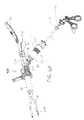
図7は、処置器具移送チューブ16のフレキシブルな先端部分を操縦するための引張ワイヤに係合したボール/ソケット・タイプのアクチュエータを使用している点において、第1の実施例とは異なる偏向可能なポート部の別の実施例を示したものである。 第1の実施例と同様に、この第2の実施例は、アクティブであってフレキシブルな端末を備え、腹腔鏡外科手術ポートとして、それ自身が機能するポート部200として構成されている。 例えば、3つのこのようなアクティブでフレキシブルなポート部200を、複数ポート部を有する腹腔鏡手術のために配置される腹腔鏡トロカールの方法と類似した方法で配置することができる。 これとは別に、2つまたはそれ以上のポート部200を、2008年9月12日出願の米国出願No.12/209,408および2009年7月28日出願の米国出願No.12/511,043に開示されたタイプのものを含む複数処置器具のアクセス装置を通して使用することができる。 図7Aには、かかる複数処置器具のアクセス装置を通して使用される際に、互いに相対して配置することができるようにした2つのポート部200が示されている。 FIG. 7 is deflectable different from the first embodiment in that it uses a ball / socket type actuator engaged with a puller wire to steer the flexible tip of the treatment
図7Aを参照すると、ポート部200には、リジッドな部分(リジッドなチューブ)218とリジッドな部分218の先端側であるフレキシブルな部分220を有する処置器具移送チューブ216が備えられている。 ポート部200の基端側部分に設けられたアクチュエータ202は、引張ワイヤ280を係合し、処置器具移送チューブ216の中に配置された処置器具の操作末端を操ることによりフレキシブルな先端部分220の偏向量を制御する。 装置のハウジング279は、処置器具移送チューブ216とアクチュエータ202を支持している。 装置のハウジング279には、ハンドル282、および/または手術テーブル、台車、手術室の天井、あるいはその他の手術室の固定物に結合された支持/安定化アームに装置を結合するためのマウント271を設けるようにしても良い。 このような目的に適した安定化アームの一例が、図22に関連して以下に説明されている。 安定化アームに結合するためのマウントは図1に示すポート部10においても同様に設けることができる。 Referring to FIG. 7A, the
第1の実施例のように、ポート部200を経由して体腔の中に展開すべき処置器具の先端側端部は、アクチュエータ202上に設けられたコントロール・チューブ224の中に挿入される。 そして、処置器具の先端側端部は、処置器具移送チューブを通って前方へ進む。 処置器具の基端側ハンドルを順々に操作してコントロール・チューブ224を動かすことにより、それに対応して処置器具の先端側端部が偏向するようになっている。 As in the first embodiment, the distal end of the treatment instrument to be deployed into the body cavity via the
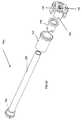
次に、引き続き図7Aを参照して、ポート部200の処置器具移送チューブの特徴について説明する。 リジッドなチューブ218は、ステンレス鋼またはその他のリジッドな管から形成され、予め固定した形状に成形されたリジッドなチューブによって構成されている。図7Aに示す実施例では、リジッドなチューブ218は、一般的に、真直ぐなメインの部分、曲がった部分または角度のついた部分218aを作り出すための曲部を有する先端領域、および曲がった部分または角度のついた部分を有する基端側部分218bを備えている。 曲がった部分または角度のついた部分の曲部の曲線は、連続的なもの、あるいは複合的なものである。 リジッドなチューブ218の真直ぐな部分および曲がった部分の長手方向の軸は、1つの平面内に置かれているが、別の実施例では、これとは異なった形態にすることもできる。 Next, the features of the treatment instrument transfer tube of the
二つのポート部200が、互いに隣接し、図7Aに示すようにポート部200の曲がった部分または角度のついた部分218aが広がっていくように配置されており、この曲がった部分または角度のついた部分218aがポート部200の先端領域を離れた位置に置いている。 そして、(切開部から体内に伸びるように配置されることになる)真直ぐな部分は、並んで配置されるようになっている。 曲がった部分または角度のついた部分を有する基端側部分218bは、アクチュエータ間の干渉が最小になるように、そしてポート部200を通って配置される処置器具のハンドル間の干渉が最小になるようにするために、アクチュエータを離れて配置するのに役立っている。The two
図7Bに示すバリエーションとしての形態では、リジッドなチューブ218のシャフトは真直ぐになっている。 別の実施例では、このシャフトは、曲がった設計の別の形状を有しており、これらは、2008年9月12日出願の米国出願No.12/209,408「発明の名称: 複数処置器具のアクセス装置およびそのシステム」、2009年7月28日出願の米国出願No.12/511,043「発明の名称: 複数処置器具のアクセス装置およびそのシステム」、および2009年12月29日出願の米国出願No.12/649,307「発明の名称: 最小侵襲の外科手術のためのアクティブな処置器具用のポート部システム」において開示されている。 In the variation shown in FIG. 7B, the shaft of the
図9を参照すると、図7Aに示す実施例のフレキシブルな先端部分220が、引張ワイヤ280(図9には図示せず)を張り渡した複数のセグメント286、288を使用して構成されている。 そして、この引張ワイヤは、処置器具移送チューブ216の先端チップ221に、あるいは先端チップ221の近傍に固定されている。 複数のセグメント286、288と先端チップ221には、中央に穴が設けられており、この穴は一つの管腔を形成するように長手方向に整合して配置されている。 セグメント286、288はソケット・ジョイントを形成するように構成されており、引張部材に作用する張力に応じて、互いに相対的にロックできるようになっている。 セグメント286、288の各々は、引張ワイヤを配置するためのガイド287を備えている。 中央の管腔を通る処置器具の動きをスムースにするために、潤滑性を有するライナーが、セグメント286、288で画成される中央の管腔を通って伸びている。 セグメント化された先端部分220は、2010年4月13日に出願した米国仮出願No.61/323,863を優先権主張の基礎とする、2010年7月29日に出願された、発明の名称が「偏向可能な処置器具用シャフト」で、発明者がShellenberger他である米国出願、に開示されている装置に使用されているセグメント化された部分に類似したものとすることができる。 Referring to FIG. 9, the
フレキシブルな内側チューブ222がリジッドなチューブ218を通って伸びている。 フレキシブルな内側チューブ222はセグメント286、288の基端側位置で終わっている先端側端部と、アクセス装置のハウジング279の中に配置された基端側端部を備えている。 内側チューブ222は、体内で使用される処置器具を受け入れるための管腔を備えている。 引張ワイヤ、ケーブル、リボン、あるいはその他のアクチュエーション・エレメント280が、内側チューブ222の壁面に設けられた管腔を通って伸びると共に、これらの管腔を出たあと、セグメント286、288の中に設けられたガイド287の中へ供給されている。 好ましい実施例では、処置器具移送チューブの各々には、周上90°の間隔で配置された4本のワイヤが備えられている。 別の実施例では、内側チューブ222の周りに等間隔配置された3本の引張ワイヤのように、異なった本数の引張ワイヤを使用することができる。 A flexible
図7Bに示すバリエーションとしての形態では、フレキシブルな先端部分220は、リジッドなチューブ218を通って伸びるフレキシブルな内側チューブ222の露出した先端部分である。 図7Aの構成でもあったように、内側チューブ222は体内で使用する処置器具を受け入れるための管腔と、引張ワイヤ280を受け入れるための引張ワイヤ用管腔(引張ワイヤ用管腔の先端側端部は図7Cに示されている)を備えている。 引張ワイヤは、内側チューブ222の先端側端部の近く、あるいは当該先端部分に結合されたチップ部分221内に固定されている。In the variation shown in FIG. 7B, the
図7Cは、引張ワイヤを固定するために使用することができる一つの形態を示したものであって、この形態では、チップ部分221は、管状キャップ221aと管状インサート211を備えた組立体となっている。 管状インサート211は、内側チューブ222の引張ワイヤ用管腔に長手方向において整合した複数の長手方向チャンネル211aを備えている。 アクセス装置が組立てられたとき、管状インサート211は、内側チューブ222の先端側端部に整合して保持されるか、あるいは内側チューブ222の管腔の中へその基端側端部を挿入することによって内側チューブ222へ物理的に結合されている。 管状インサート211のチャンネル211aの中には、引張ワイヤ214が配置され、管状キャップ221aは管状インサート211と内側チューブ222の先端側端部の外側に圧入されており、その結果引張ワイヤ214がチャンネル211aの中に保持されるようになる。 このような引張ワイヤ214の先端側端部を保持するための圧入技術は、ここで開示する各実施例においても適用することができる。 引張ワイヤ214が引張ワイヤ用管腔の中に引き戻されることがないように引張ワイヤ214の先端側端部を圧着するような、その他の技術を利用することもできる。 FIG. 7C shows one form that can be used to secure a puller wire, in which the
フレキシブルな内側チューブ222の中を通る引張ワイヤは、フレキシブルな先端部分220を偏向させる引張ワイヤに作用するアクチュエータ202に結合されているので、フレキシブルな内側チューブ222は、ねじれに対する適度な耐性を有する一方、処置器具を操作するために必要なだけ偏向できるように十分な柔軟性を有するように構成されている。
ある実施例では、フレキシブルな内側チューブ222は、管腔を覆うPFTE内側ライナー、当該ライナー覆うように配置された熱可塑性シース(当該シースを通って形成された引張ワイヤ用の管腔を有している)、熱可塑性シースを覆って配置された強化層、および強化層を覆って配置された第2の熱可塑性シースを使って形成された複合チューブとなっている。
別の実施例では、第2の熱可塑性シースは省略され、強化層が外側のシースとして機能するようになっている。 更に別の実施例では、強化層が内側チューブ222の最も内側の層を構成するようにすることもできる。 強化層の無いものや、強化材料またはその他の材料からなる追加の層を備えたものなど種々の実施例が適用可能である。The tension wire passing through the flexible
In one embodiment, the flexible
In another embodiment, the second thermoplastic sheath is omitted and the reinforcing layer functions as the outer sheath. In yet another embodiment, the reinforcing layer may constitute the innermost layer of the
図8はアクチュエータ202の詳細を示したものであり、2008年9月12日に出願された米国出願12/209,408および2009年7月28日に出願された米国出願12/511,043で開示されたアクチュエータと類似の特徴を備えたものであっても良い。 各アクチュエータ202は、コントロール・チューブ224と、外科手術用処置器具を通すための基端側入り口ポート258を備えている。 入り口ポート258は、その中を通過する処置器具のシャフトに対してシーリングするための隔膜シールを備えている。 コントロール・チューブ224は、好ましくは内側管状ライニング223を備えており、内側管状ライニング223は、処置器具がアクチュエータの中を容易に滑って挿入することができるように、好ましくはPTFEあるいはその他の適切な材料からなる潤滑性材料によって形成されている。 基端側のジンバル部分260はコントロール・チューブ224の先端側端部に結合されている。 基端側のジンバル部分260には、先端側に面したソケット262が備えられている。 先端側のジンバル部分266には、基端側のジンバル部分260の先端側に面したソケット262の中に部分的に配置され、部分的な球面を有するボール部分264が備えられている。 ボール部分264は、ボール部分264からアクセス装置のハウジング279の中へ入る先端側へ伸びた管状のハウジング270を更に備えている。 フレキシブルな内側チューブ222(図8には図示せず。図7Aと7Bを参照のこと)は、管状のハウジング270の径が小さくなった先端部分263の中まで伸び、そして先端部分263に結合されている。 管状のハウジング270に設けられた側面の開口部225は、アクセス装置のハウジング279の中に配置され、ルアー・ポート284に流体的に結合されている。 FIG. 8 shows details of the
内側管状ライニング223は、基端側のジンバル部分260と先端側のジンバル部分266を通って伸び、その先端側端部フィッティング281によって管状のハウジング270の中で固定されている。 バルブ283は、クロス・スリット、ダックビルバルブでもよく、管状のハウジング270の中に配置されている。 このバルブは、処置器具がアクチュエータの中に配置されていない時に、膨張ガスが流失するのを防止するようにアクチュエータをシールする機能を有する。The inner
引張ワイヤ280は、フレキシブルなチューブ220の基端側端部を出て、アクセス装置のハウジング279の外へ伸びており、基端側のジンバル部分260に結合されている。 The
アクチュエーション・システムを使用している間は、処置器具Iのシャフトは、コントロール・チューブ224、基端側のジンバル部分260、先端側のジンバル部分266等を通って伸び、そして、処置器具の操作端が体腔の中に配置されるように処置器具移送チューブの中を通っている。 適切な処置器具は、コントロール・チューブ224の中に配置されるか、コントロール・チューブ224に接触して配置されるリジッドな基端部分とフレキシブルな先端部分を備えている。 処置器具の先端側端部を思い通りに動かすために、外科医はその処置器具のハンドルを動かし、コントロール・チューブ224をハンドルと一緒に動かす。 基端側のジンバル部分260は先端側のジンバル部分266のボール部分264の表面上を動き、その結果、基端側のジンバル部分260の先端側のジンバル部分266に対する相対的な角度に従って、引張ワイヤに張力が付加されることになる。 処置器具移送チューブの引張ワイヤに対するジンバルの動きの結果、処置器具の先端部分は偏向することになる。 従って、処置器具の先端側端部を上方へ持ち上げることを希望するならば、ユーザーはハンドルを下方へ押し下げ、基端側のジンバル部分260をボール部分264の表面上を下方へ動かす。 その結果、上側の引張ワイヤ280に張力が作用し、処置器具の先端側端部と処置器具移送チューブが一緒に上方へ偏向することになる。 処置器具のシャフトを右側横方向へ動かすことにより、対応する側方に置かれた引張ワイヤに張力が付加され、処置器具移送チューブの先端部分が左に曲げられる。 このアクチュエータ・システムは、垂直方向と横方向の偏向を組み合わせて、処置器具移送チューブに対して360°の偏向を与えることができるようになっている。 別の実施例では、フレキシブルなチューブ220の動きがコントロール・チューブ224の動きに合うように引張ワイヤを引き回すようにすることもできる(例えば、コントロール・チューブ224を持ち上げることにより、処置器具移送チューブ216の先端側端部と処置器具が上方へ持ち上げられるようになる)。While using the actuation system, the treatment instrument I shaft extends through the
ユーザは、更に、必要があれば、処置器具移送チューブの中を長手方向に、ツール(処置器具)を前へ進めたり後ろへ引き戻したりすることができ、及び/又は、処置器具移送チューブの中で処置器具を軸周りに回転させることもできる。 ここで、ボールとソケットの配置を逆にすることもできることに注意すべきである。 すなわち、基端側のジンバル部分がボール部分を備え、先端側のジンバル部分が、ボール部分が関節運動できるようになっているソケットを備えている。 The user can further move the tool (treatment instrument) forward and backward, if necessary, longitudinally through the treatment instrument transfer tube, and / or in the treatment instrument transfer tube. The treatment instrument can also be rotated around the axis. It should be noted here that the ball and socket arrangement can be reversed. That is, the base end side gimbal portion includes a ball portion, and the distal end side gimbal portion includes a socket that allows the ball portion to articulate.
ポート部200が単独のポートとして機能するものであれば(すなわち、別のトロカールや別のアクセス装置を通して導入されるものではない)、先端側のジンバル部分266は、体壁を貫通して形成された切開部(またはトロカール用穴のようなその他の開口部)の中に着座する形状をしたハウジング279を備えるか、あるいはこのハウジング279に結合するようにしても良い。 図示する実施例では、ハウジング279は、切開部の中でシーリングするのを容易にするために、基端側に向かって広がっている。 ハンドル282はハウジング280から伸び、ユーザがポート部200を手で支持できるようになっている。(ポート部200は、手術台に結合された支持アームに取り付けることができるようにするマウント271のような構成のものを追加的に設けたり、あるいはハンドル282の代わりに設けたりすることもできる。) If the
ハウジング279に設けたルアー・ポート284(図7A参照)、ハンドル282(図7B)、あるいはハウジング279の別の部分は、処置器具移送チューブに流体的に結合されており、処置器具移送チューブを通じて注入ガスまたは洗浄流体を体腔内に導入できるようになっている。Luer port 284 (see FIG. 7A), handle 282 (FIG. 7B) on
図示する実施例の設計では、ユーザーは、リジッドなチューブ218の長手方向軸に対して相対的に、ハンドル282を軸周りに回転できるようになっているので、ユーザーは、ハンドル282の位置に対して相対的にリジッドなチューブ218の曲部の向きを選択できるようになっている。 複数のユニットからなるポート部200の対応するリジッドなチューブの曲部を必要な配置になるように方向を選択し、各ユニットのハンドルの位置決めをすることにより、複数のユニットからなるポート部200を単一の手術に使用することができる。 例えば、図7Aでは、2つのポート部200が配置され、左側のポート部では、リジッドなチューブの曲部が他方のリジッドなチューブの曲部とは逆の方向を向いている。 この配置では、ポート部の先端側端部および基端側端部が、ハンドル282の1つが逆さまの状態にしなくとも、かつ、別のバージョンのポート部を新たに作らなくとも(例えば、一つのポート部では、右側に曲がった曲部を有し、もう一つのポート部では、左側に曲がった曲部を有する)、互いに広がるように配置できるようになっている。 The design of the illustrated embodiment allows the user to rotate the
図10は、ハンドル282がアクチュエータ202および処置器具移送チューブ216に対して相対的に回転できるようにしたメカニズムの1例を示すものである。 ハンドル282は、先端側端面の半径方向に配置された複数の歯294を備えたハンドル・リング292に結合されている。 カプラー・リング290は、図11に示すように基端側端面に内側に伸びるリップ部296を備えており、当該リップ部296上に配置された歯298を備えている。 FIG. 10 shows an example of a mechanism that allows the
再び図10を参照すると、ハウジング279は、ハンドル・リング292を通り、カプラー・リング290の中へ伸びる先端側伸長部300を備えている。 圧縮スプリング302は、先端側伸長部300の周りに配置されている。 図12に最も良く示されているように、圧縮スプリング302は、先端側伸長部300の廻りに配置されたスリーブ304によって保持されていると共に、ピン305によってカプラー・リング290へ結合されている。 圧縮スプリング302は、その基端側端部がリップ部296の先端側端面に接触して着座しており、その先端側端部はスリーブ304に係合している。 圧縮スプリング302は、カプラー・リング290に対して、カプラー・リング290の基端側方向にバイアスをかけており、カプラー・リング290の歯298がハンドル・リング292の歯294に係合するようになっている。 ハンドル282の回転軸廻りの位置を変更するために、図12の矢印で示すように、カプラー・リング290が、スプリングのバイアスに対抗して先端方向へ押され、その結果、歯294と歯298の係合が外れる。 その時、処置器具移送チューブ216の長手方向軸に対して相対的にハンドル・リング292を回転させることによって、ハンドル・リング292は、ハウジング279に対して相対的に軸廻りに自由に回転できるようになる。 一旦ハンドル282が所望する位置に配置されると、カプラー・リング290はユーザーの手から離される。 スプリング302は、カプラー・リング290を基端側へ動かし、歯294と歯298が再び係合し、その結果、ハンドル282が不注意により回転してしまわないようにロックされる。 Referring again to FIG. 10, the
図13は、図7Aに示すポート部200に類似する別のポート部200aを示すものである。 そして、このポート部200aは、アクセス装置を通して、あるいは切開部を直接通してポート部200aを挿入する際に、ポート部200aの挿入が容易になるように、リジッドなチューブの先端側端部(フレキシブルなチューブ220の基端側)を、最初はフレキシブルな状態にしておくために多少改造されている。 しかし、この部分は、実質的に予め設定されたリジッドな形状をとるようになっている。 この実施例では、リジッドなチューブ218aは、固定された形状を有するメイン・リジッド・シャフト217a、と複数のシャフト・エレメント219から形成されたセグメント化シャフト217bから構成されている。 FIG. 13 shows another
図14は、シャフトの他の部分から離れて配置された1つのシャフト・エレメント219を有する処置器具移送チューブ216aの先端側端部を示すものである。 シャフト・エレメント219は、フレキシブルなチューブ222の廻りに数珠つなぎ状になっている。 前に述べた実施例のように、フレキシブルなチューブ222には、その外壁に設けられた引張ワイヤ用の管腔が設けられており、引張ワイヤ用の管腔を出た引張ワイヤ(図示せず)は、フレキシブルなチューブ220(フレキシブルな先端側部分)のセグメント286、288の中に設けられたガイド287の中へ入っている。 この実施例では、追加された引張ワイヤ291が、リジッド化可能な部分217bをリジッドな状態にするために備えられている。 この引張ワイヤ291はシャフト・エレメント219に設けられた管腔の中を通りぬけ、フレキシブルなチューブ222の外表面に沿って伸び、その先端はエレメント293に結合されている。 シャフト・エレメント219の管腔は引張ワイヤ291を収納するための側方チャンネルまたは隙間221であっても良い。 FIG. 14 shows the distal end of a treatment
図15を参照すると、引張ワイヤ291は、引張ワイヤ291の基端側端部に結合されたアクチュエーション・リング295を使用して操作されるようになっている。 アクチュエーション・リング295は、処置器具移送チューブ216aのシャフト上を長手方向にスライドできるようになっており、アクチュエーション・リング295を基端側方向へ引き寄せることにより、リジッド化可能な部分217bはリジッドな状態になる。 リジッド化可能な部分217bをリジッドな状態に維持するためのロック・システムは、アクチュエーション・リング295によって運ばれるトリガー297を備え、そしてラチェット・スリーブ299の歯とかみ合う回転可能なくさび297aを有している。 板バネ(図示せず)が、トリガー297にバイアスをかけることにより、ユーザーがトリガー297を押圧するときを除き、くさび297aはラチェット・スリーブ299の歯とかみ合うようになっている。 リジッド化可能な部分217bをリジッドな状態にするために、ユーザーはロック・システムのロック解除を行うためにトリガー297を押圧し、それから引張ワイヤ291に張力を付与するためにアクチュエーション・リング295を基端側方向へ引っ張り、そしてトリガー297を解放することにより、アクチュエーション・リング295はラチェット・スリーブ299に再び係合することになる。 リジッド化可能な部分217bをフレキシブルな状態に解放するために、トリガー297を押圧してロック・システムのロック解除を行い、引張ワイヤ291の張力を解放するために、アクチュエーション・リング295を長手方向前方へスライドさせる。 Referring to FIG. 15, the
シャフト・エレメント219は、引張ワイヤ291に張力が付与されたとき、シャフト・エレメント219の各々の先端側面は、先端側に隣接するシャフト・エレメント219の基端側面に完全に接触し、その結果、シャフトは所定の形状をとるように形作られている。 所定の形状としては、好ましくは図示するような曲線形状である。 図7Aに示す実施例に関連して説明した軸廻りに回転可能なハンドルの特徴点については、本実施例においても適用することができ、それによって必要な方向に向けられたリジッド化可能な部分(シャフト部分)217bの曲線形状に従って処置器具移送チューブ216bを配置することができることに留意が必要である。 When the
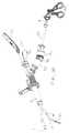
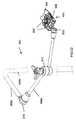
図7Aに示す実施例の変形である別のポート部200bを図16に示す。 ポート部200bが図7Aに示すポート部200と異なる点は、主に、リジッドなチューブ218の先端側端部にある関節ジョイント306の内包物とこの関節ジョイント306用のアクチュエータにある。
リジッドなチューブ218は、フレキシブルな部分220(フレキシブルなチューブ220)のセグメントの基端側に隣接する先端側部材310aと、中間部材310bと、固定した曲部形状を有する基端側部材310cとを備えている。 図17Aを参照すると、関節ジョイント306は、先端側部材310aと中間部材310bとの間に配置されており、先端側カプラー312aと基端側カプラー312bから構成されている。 図17Bの側方立面図に最も良く示されているように、先端側カプラー312aの基端側面には凸状面又はサドル状面が形成されており、基端側カプラー312bの先端側面は突起を形成するようにテーパが設けられており、前記サドル状面の中に着座するようになっている。 従って、このジョイントはロッカー・ジョイントを形成している。FIG. 16 shows another
The
ステンレス・スチールまたはその他の適切な材料からできた一対の細長いリボン又はシート314は、先端側カプラー312aの対向する側面に回転自在に結合された先端側端部を有している。 このシート314は、基端側カプラー312bの外表面に沿って基端側へ伸び、中間部材310bの外表面に形成されたスロット又は窪み316を通るようになっている。 このシート314は、ジョイントが屈曲するとき、スロット又は窪み316のある領域において曲げられるようになっている。 A pair of elongated ribbons or
再び図16を参照すると、リジッドなチューブ218の基端側部材310cの位置において、基端側部材310cの中に配置された内部チャンネル318(図示せず)の中へ細長いシート314が入り込むようになっている。 リジッドなチューブ218の基端側部材310cは、複数のセグメントで構成されているように図示されているが、代わりに単一の部材を使用することもできる。 Referring again to FIG. 16, at the location of the
細長いシート314の基端側端部は、基端側部材310cの基端側端部を出て、図19に示すように、アクチュエータ308の対向する側方翼部に固定されている。 アクチュエータ308は、ピボットにより取り付けられている。 このピボットとしては、基端側部材310cの基端側端部から伸びたハイポチューブ・カプラー322に結合されたリベット320により構成されるものがある。 アクチュエータ308を一つの方向へ回転させると、細長いシート314の一方のものは引き寄せられ、細長いシート314の他方のものは、前方へ出ていくようになっている。 その結果、関節ジョイント306が、一方向へ屈曲する。 アクチュエータの一方の側方が先端側へ出るように回転するとき、各シート314が対応するローラの廻りで湾曲できるようにローラ324が配置されている。 このようにすることによって、シート314がよじれるのを防止することができる。 The base end side end of the
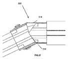
使用する際、ユーザーは、関節ジョイント306が必要な方向へ向くようにアクチュエータを操作する。 図20Aの矢印で示すようにアクチュエータ308を回転させると、図20Bに示すような位置に関節ジョイント306が屈曲し、一方、アクチュエータ308を逆の方向へ回転させると、関節ジョイント306は逆の方向へ屈曲する。 図21は、関節ジョイント306の位置と関節ジョイント306が屈曲している時の曲げ領域315におけるシート314の曲げの状態を示したものである。 アクチュエータには、屈曲する部分において生じた曲がりを保持するために、アクチュエータの回転した状態保持するロック(図示せず)を備えるようにしても良い。 In use, the user operates the actuator so that the joint joint 306 is oriented in the required direction. When the
図22は、ここで開示したポート部を支持するために使用する安定化アーム600の例を示したものである。 安定化アームには、Spider(登録商標)医療用システムと一緒使用されるアームであって、TransEnterix, Inc, of Durham, NCによって販売されている安定化アームにおいて見られる特徴点を備えるようにすることができる。 FIG. 22 shows an example of a
安定化アーム600は、ポート部の球状マウント271(図7A参照)に結合できるように設計されたクランプ602を備えており、ポート部を無限の数の方向に向けることができるようになっている。 クランプ602は、マウント271を受け入れるための開口部606を画定するクランプ半端604を備えている。 レバー607を回転することにより、クランプ半端の間にマウント271をクランプするために、クランプ半端を互いに引き寄せるようになっている。 クランプ602は、ユニバーサル・ジョイント610(ボール・アンド・ソケット)又はピボット・エルボ・ジョイント612によって相互接続されたアーム部材608a-cの集合体に取り付けられている。 ジョイントの組み合わせにより、安定化アームは、ポート部をユーザが選択したいかなる方向に向けても支持できるようになっている。 基端側のアーム部材608cは、手術台あるいは手術室の中に在る別の固定物に結合される。 Stabilizing
ポート部をクランプ602に取り付けるために、球状マウント271又はポート部は、クランプ半端の間に配置される。 ユーザーは、3次元空間の必要な方向へ向けてポート部を置き、そして、球状マウント271をクランプするために、レバー606を閉じてラッチをかける。 手術中のある時に、ユーザーがポート部の方向を調整する必要が生じた場合、ユーザーはクランプ半端のラッチを解除して、調整することになる。 クランプ602と球状マウント271の間の結合状態としては方向自在性があり、アーム部材間には調整可能なジョイント610、612が存在するので、ユーザーはポート部のピッチ、ロール、およびヨー方向を変えることができるようになっている。 To attach the port portion to the
ここで説明したポート部10、200、200a、200bは、種々のタイプの手術において使用することができる。 ポート部は、互いに物理的に結合されていない個々のユニットとして製造されるので、複数のポート部システムを、一緒に使用できるようになっているが、個別に独立して配置、再配置ができるようになっている。 以下の議論では、ポート部の使用を容易にするポート部システム(コンポーネントのシステム)と一緒に、ポート部の使用方法に関するいくつかの例を説明する。 一つの例では、2つ、3つ、あるいはそれ以上の数のアクティブであって、フレキシブルなポート部が、腹腔鏡用トロカールがマルチポート腹腔鏡手術のために配置されるのと類似の方法で、別の切開部を通して配置されている。 The
このアプリケーションでは、外科医が従来の腹腔鏡に類似した方法で処置することができるようになっているが、従来のトロカール用ポートを通したリジッドな処置器具を使用することにより達成できる動きよりも更に大きな範囲の動きを実現することができる。 このアプリケーションにおけるポート・システムでは、複数のアクセス装置(もし、使用するのであれば)、2つ以上のポート部100、200、200a、200b、およびポート部用の安定化アームを備えている。 This application allows the surgeon to treat in a manner similar to a conventional laparoscope, but even more than the movement that can be achieved by using a rigid treatment instrument through a conventional trocar port. A large range of motion can be realized. The port system in this application includes a plurality of access devices (if used), two or
この手術では、皮膚及び下層組織を通して3つ又は4つの切開部が形成される。 トロカール又はその他のシールされたアクセス装置が、各切開部を通して配置される。 そして、各ポート部の先端側端部がアクセス装置の一つの中に挿入され、体腔の中を前方に進められる。 いくつかのアクセス装置が、スコープやステープラーのようなポート部以外の装置を受け入れるために使用される。 もし、必要であれば、別のアクセス装置を用いることなくポート部を使用することもできる。 そのような場合、ポート部の先端側端部は、直接切開部を通って挿入され、体腔内を前方へ進められる(アクセス装置が、スコープやその他の処置器具のために使用されるとしても)。 体腔を膨らませるために、注入ガスが、ポート部又はアクセス装置を通じて注入される。 各ポート部は、専用の安定化アーム600(図22参照)に結合され、必要な方向に向けて配置され、そして安定化アームを使って選択した方向にロックされる。 ポート部を方向づけするために、図10から図12に関連して述べたように、リジッドなチューブに対して、相対的にハンドルの回転位置を調整する。 ここで、ポート部のハンドル282を上方に向けて配置する、すなわちポート部を安定化アーム600から吊り下げるようにすることは好ましいことであることに注意が必要である。 In this surgery, three or four incisions are made through the skin and underlying tissue. A trocar or other sealed access device is placed through each incision. The distal end of each port is inserted into one of the access devices and advanced forward through the body cavity. Some access devices are used to accept devices other than the port section, such as scopes and staplers. If necessary, the port section can be used without using a separate access device. In such a case, the distal end of the port portion is inserted directly through the incision and advanced forward through the body cavity (even if the access device is used for a scope or other treatment instrument). . Insufflation gas is injected through the port or access device to inflate the body cavity. Each port portion is coupled to a dedicated stabilization arm 600 (see FIG. 22), positioned in the required direction, and locked in the selected direction using the stabilization arm. To orient the port portion, the rotational position of the handle is adjusted relative to the rigid tube, as described in connection with FIGS. It should be noted here that it is preferable to position the
もし、図13に示すポート部200aを使用するとすれば、トリガー297はセグメント219を湾曲させリジッドになるように、引き込むために係合するようになっている。 もし図16に示すポート部200bを使用するとすれば、関節ジョイント306は、ポート部の先端側端部を選択された方向に向けるために屈曲するようになっている。 If the
手術を行うために使用すべきフレキシブルな医療用処置器具は、ポート部を通って前方へ進み、アクチュエータへの係合を通じてポート部の先端側端部を操縦し、偏向させるためにポート部のハンドルが操作される。 もし、図20Aに示すポート部の実施例を使用するとすれば、手術中、医療用処置器具の先端側端部の配置を更に調整できるようにするために、関節ジョイント306が屈曲できるようになっている。 A flexible medical treatment instrument to be used to perform a surgery advances forward through the port portion, and handles the port portion to steer and deflect the distal end of the port portion through engagement with the actuator. Is operated. If the embodiment of the port portion shown in FIG. 20A is used, the joint joint 306 can be bent during surgery to allow further adjustment of the placement of the distal end of the medical treatment instrument. ing.
切開部の中におけるポート部全体としての位置決めは、手術中に種々の方法で行われる。 例えば、ポート部のピッチおよびヨー方向は、安定化アームによって調整される。 ポート部は、図10から図12に関連して説明したようにハンドルに対して相対的なリジッドなチューブの回転位置を調整することによって、切開部の中において軸廻りに回転される。 ポート部を切開部に対して相対的に長手方向に前進させ、又は後退させることにより、ポート部とそれに対応する処置器具のZ軸方向の動きを与えることになる。 処置器具の細かい位置決めは、ポート部の先端側端部の偏向、ポート部内での処置器具の軸廻りの回転、あるいはポート部内における処置器具の長手方向またはZ軸方向の動きを通じて、同様に実施できる。 Positioning of the entire port portion in the incision portion is performed by various methods during the operation. For example, the pitch and yaw direction of the port part are adjusted by the stabilizing arm. The port portion is rotated about the axis in the incision by adjusting the rotational position of the rigid tube relative to the handle as described in connection with FIGS. By advancing or retracting the port portion in the longitudinal direction relative to the incision portion, movement of the port portion and the corresponding treatment instrument in the Z-axis direction is given. Fine positioning of the treatment instrument can be similarly performed through deflection of the distal end portion of the port portion, rotation of the treatment instrument about the axis in the port portion, or movement of the treatment instrument in the longitudinal direction or Z-axis direction in the port portion. .
図23Aは、共通するアクセス装置700と組み合わせた2つの図13に示すポート部と、ポート部の1つ又は両方を保持するための安定化アーム(図示せず)を示したものである。 アクセス装置は、2008年9月12日出願の米国出願No.12/209,408「発明の名称:複数の処置器具のアクセス装置およびシステム」に開示されたものと類似の特徴点を有するものであっても良い。 図23Bに示すように、アクセス装置700は、体壁に形成された開口部(例えば、切開部または穿孔)の中に配置可能なベース702と、ベース702に設けたシール704とを備えている。 このシール704は、好ましくは、使用中体外に配置されるように設置される。 このシール704は、大きな装置(例えば、当該システムを使用してインプラントするための胃緊縛用バンド)をベース702を通して直接体腔の中へ入れることができるようにするために、ベース702に取り外し可能なように取り付けても良い。 FIG. 23A shows two port portions shown in FIG. 13 combined with a
シール704は、ポート部およびその他の処置器具を受け入れるための複数の開口部706を備えている。 この実施例では、開口部706は、ベース702から基端側に伸びる指状管708a、708bの中にある。 開口部706は、等しい直径を持つように構成しても良いし、異なった径を持つようにしても良い。 図23Bに示すアクセス装置は、3つの指状管を備えており、2つの隣り合った指状管708aと、2つの指状管708aの中央であってそれらの上方置かれた3つ目の指状管から構成されている。 ベース702は、指状管708a、708bの配列を通して使用されるポート部/処置器具のシャフトを収納するために、一般的に三角形状の開口部710を備えている。 クロス・スリット又はダックビルバルブのようなバルブ(図示せず)が、指状管の中にポート部又はその他の処置器具が挿入されていない時に、注入ガス圧の損失が生じないように指状管部をシールするために、各指状管の中に配置されている。 しかし、ガス注入が必要なときに、常にポート部が各指状管の中に配置されているような場合には、このシールを省略することもできる。 指状管の中に配置されたポート部又はその他の処置器具のシャフトに対してシールするために、指状管の中にガスケット・シールを配置するようにしても良い。
図23Aに示すシステムを使用する場合には、切開部は皮膚及び下層組織を通して形成され、切開部を通って伸びるベース702と一緒にアクセス装置が配置される。 各ポート部200aの先端側端部は、指状管708aの一つの中へ挿入され、体腔内へと進められる。 スコープ712又はその他の装置(例えば、別の切開部を使用して、あるいはポート部の一つを通して可視化が必要であれば、オプションとしての第3のポート部)を、指状管708bを通して体腔の中へ挿入することができる。 アクセス装置の膨張ポートあるいはポート部200aの一つに設けられたルアー・ポートを通して直接膨張ガスを注入することにより体腔は膨張させられる。 各ポート部は、必要とする方向に配置され、上述したような技術を使用して選択した方向にロックされたそれぞれ専用の安定化アーム600(図22参照)に結合される。 When using the system shown in FIG. 23A, an incision is made through the skin and underlying tissue, and the access device is placed with a base 702 extending through the incision. The distal end of each
安定化アームに結合するために、ポート部200aのハンドル282が図示する方向に向けられ、あるいは上方に(図示する方向とは逆の方向)又は別の方向に向けられる。 ここで、特筆すべきことは、各ハンドル282の回転位置は、メイン・リジッド・シャフト217aの曲部が望ましい方向に向くように選択される、ということである。 従って、図23Aに示すように、鏡像の位置関係になるようにするために、シャフト217の一つが他方のシャフトに対して相対的に、長手方向軸廻りに逆向きになるように設定される。 To couple to the stabilization arm, the
各ポート200aのトリガー297は、セグメント219が曲線状のリジッドな方向を持つように、セグメント219を引き寄せるために係合しており、その結果、体の中でポート部200aが離れた状態になる。 The
手術をするために使用されるフレキシブルな医療用処置器具は、ポート部を通って前方へ進められ、アクチュエータとの係合によってポート部の先端側端部を操縦/偏向させるためにポート部のハンドルが操作される。 ポート部200aと処置器具の位置調整は、上述した手順を通じて行うことができる。 A flexible medical treatment instrument used to perform surgery is advanced forward through the port portion and a handle on the port portion for steering / deflecting the distal end of the port portion by engagement with an actuator. Is operated. The position adjustment of the
図24は、図16に示す二つのポート部200bが図23Bに示すアクセス装置700と基本的に類似するアクセス装置700aの3つの指状管を通って伸びるポート部システムを使用する状況を示したものである。 このシステムを使用方法は、図23Aに関連して述べたシステムの使用方法と類似するが、関節ジョイント306を操作するためのアクチュエータ308を使用し、関節ジョイント306の屈曲角度を仮に固定するためにアクチュエータ308をロックすることが必要になる点において異なる。 図24は、アクセス装置700aを通して二つのポート部200bを異なった距離だけ前方へ進めた状態を示すものであり、ポート部とそれに対応する処置器具のZ軸方向位置を独立して位置決めできるポート部を使用した状態を示している。 FIG. 24 illustrates a situation where the two
別の例として、前述したポート部10、200、200a、200bの一つを、単一のポート部による生体検査を行うために使用するようにしても良い。 ポート部200aを使い、このような手術を行うために適切なポート部システムを図25に示してある。 この種の手術では、内視鏡と同時にポート部200aが、体壁に設けられた切開部の中に配置されたトロカールやその他のアクセス装置を通して挿入される。 図25は、処置器具又はポート部のシャフトを受け入れるための一対の開口部を備えた弾性シール701を有するアクセス装置700bを示したものである。(そして、この弾性シールは、好ましくはこれらのシャフトに対してシーリングを行うものである。) 上述したように、クロス・スリット又はダックビルバルブをアクセス装置700bの中で使用することができる。 ポート・エクステンション部700cが一つの開口部に配置されている。 このポート・エクステンション部700cは、リジッド・チューブ720と、基端側開口部724を有する基端側ハウジング722と、好ましくはポート・エクステンション部700cの中を通る処置器具に対シーリングするシールから構成されている。 このシールは、開口部724を有し、キャップ728によりハウジングに保持される隔膜タイプのシールであっても良い。 ハウジング722は、ポート・エクステンション部700cを通って伸びる処置器具が存在しない時に、当該ポート・エクステンション部700cをシールするために、バルブ又はシール(例えば、クロス・スリット・シール730又はダックビルバルブ)を備えている。 リジッド・チューブ720は、オプションとして、図25に示すように、アクセス装置700bの開口部の中へ挿入できるフレキシブルな管状プラグのような基端側コネクター732を備えることもできる。 前に述べた実施例のように、図25に示すポート・システムは、安定化アーム(図示せず)を備えるようにしても良い。 As another example, one of the
スコープ712が、ポート・エクステンション部700cを通って配置されている状況が図示されている。 ポート・エクステンション部700cはオプションであるが、ポート・エクステンション部700cによってユーザーはポート部200bのアクセス・ポイントよりも更に基端側、すなわちポート部200bの折れ曲がった基端部分の側方位置においてスコープまたは処置器具のためのアクセス・ポイントを利用できるようになっている。 これにより、ユーザーはポート部200bのシャフトによってユーザーの手が邪魔されることなくアクセス装置700bを通して処置器具を挿入することができるようになる。 The situation where the
以上とは別に、生体検査のために使用されるポート部10、200、200a、200bのハウジングは、内視鏡を受け入れるための管腔又はサイド・カー・サポートを備えることができ、これにより、別のトロカールやアクセス装置を用いることなくポート部を使用することができるようになる。 同様な配列のものを経肛門(TEM)手術(例えばポリープ除去)、経胃手術、経膣手術、あるいは経胸腔手術に使用することができる。 このような手術では、ポート部10、200、200a、200bの内の二つを開口部を通して横に並べて配置することができる。 Apart from the above, the housing of the
別の例として、先行する出願において説明しているアクセス装置のパッシブなポート部の一つに、ポート部10、200、200a、200bを通すようにすることもできる。 そしてここでこれらの出願に言及することにより、本明細書に取り入れられるものとする。 例えば、このようなアクセス装置としては、2009年12月29日出願の米国出願No.12/649,307「発明の名称:最小の侵襲的外科手術のためのアクティブな処置器具用ポート部システム」に開示されたアクセス装置があり、これらのアクセス装置には追加的でアクティブなポート部を有効に追加できるようになっている。 肥満治療のための胃緊縛用バンドをインプラントする手術の例では、これらのアクセス装置のアクティブなポート部の処置器具移送チューブが、組織を把持するように操作される把持器具と一緒に使用される。 アクティブなポート部の間に配置されたパッシブなポート部を通して伸びるポート部10、200、200a、200bは、胃緊縛用バンドを取り付け胃の廻りを引き締めるために、胃の後腹部側のあたりを把持する輪なわ又はその他の把持装置を操作するために使用することができる。 As another example, the
以上例示した応用例やポート・システムは、単に代表的なものであって、包括的なものであると考えるべきものではない。 ここで開示したポート部やポート・エクステンダーは、開示されたアクセス装置(将来開発されるであろう別の装置や当該技術分野に精通する者に知られている装置を含む。 例えば、US2006/0020241、US2008/0086167、US2008/0255519等に開示されたもの)のいずれとも一緒に使用することができる。 そして、ポート・システムには、同じタイプ(例えば、図24に示すもの)のポート部を複数使用したシステムや、異なったタイプのポート部を組み合わせたシステムが含まれる。 The applications and port systems illustrated above are merely representative and should not be considered comprehensive. Ports and port extenders disclosed herein include the disclosed access devices (other devices that will be developed in the future and devices known to those skilled in the art. For example, US2006 / 0020241 , US2008 / 0086167, US2008 / 0255519, etc.). The port system includes a system that uses a plurality of port portions of the same type (for example, those shown in FIG. 24) and a system that combines different types of port portions.
以上実施例について説明してきたが、これらの実施例は例示として示したものであって、これらに限定されるものではないことを理解しなければならない。 本発明の思想や範囲から外れることなく、形態や細部をいろいろ変えることができるということは、当業者にとっては自明のことである。 特にこのことは、後で開発される関連技術に包含される技術や用語を考慮すれば、真実である。 更に、ここで開示された種々の実施例の特徴点を組み合わせることによって、種々の追加的な実施例を生み出すことができる。 Although the embodiments have been described above, it should be understood that these embodiments are shown by way of example and not limitation. It will be apparent to those skilled in the art that various changes in form and detail can be made without departing from the spirit and scope of the invention. This is particularly true when considering the techniques and terminology included in the related technologies that will be developed later. Furthermore, various additional embodiments can be created by combining the features of the various embodiments disclosed herein.
上述したいずれかの、又は全ての特許、特許出願、刊行物は、優先権主張のためのものを含め、ここで参照することにより、本明細書に取り入れられるものである。
Any or all of the patents, patent applications, and publications discussed above, including those for priority, are hereby incorporated by reference.
Claims (16)
Translated fromJapanese細長いチューブのリジッドな部分に結合された第1のアクチュエータであって、当該第1のアクチュエータは管腔に連通した処置器具用通路を備え、処置器具用通路は、医療用処置器具の先端側端部が当該処置器具用通路と管腔を通って挿入でき、管腔の先端側端部から出て、体腔の中へ入るように配置されている第1のアクチュエータと、
第1のアクチュエータと偏向可能な部分の間に伸びた複数のアクチュエーション・エレメントであって、偏向可能な部分を偏向させるために、処置器具用通路と管腔の中に配置された医療用処置器具の基端側端部を操作してアクチュエーション・エレメントを動かすようになっているアクチュエーション・エレメントと、
関節ジョイントの先端部分と、間接ジョイントを屈曲させるためにリボンの一つを選択的に引き込む第2のアクチュエータであって、第1のアクチュエータとは独立して操作できる第2のアクチュエータとの間に伸びる一対のリボンと、
細長いチューブに結合されたマウントであって、手術室内の安定化アームに係合可能なマウントと
を備えたことを特徴とする処置器具用ポート部。An elongate tube with a lumen, a rigid part having a fixed shape, a deflectable part on a distal side ofthe rigid part, and an articulated joint between the rigid part and the deflectable part; An elongated tube consisting of
Afirst actuator coupled to a rigid portion of an elongate tube,the first actuator comprising a treatment instrument passage communicating with a lumen, the treatment instrument passage being a distal end of the medical treatment instrument Afirst actuator that can be inserted through the treatment instrument passage and lumen, and is disposed to exit the distal end of the lumen and into the body cavity;
A plurality of actuation elements extending betweenthe first actuator and the deflectable portion, the medical procedure disposed within the treatment instrument passage and lumen to deflect the deflectable portion An actuation element adapted to move the actuation element by manipulating the proximal end of the instrument;
A second actuator that selectively pulls one of the ribbons to bend the indirect joint, and a second actuator that can be operated independently of the first actuator; A pair of extending ribbons;
A treatment instrument port comprising: a mount coupled to an elongated tube, the mount being engageable with a stabilizing arm in an operating room.
前記リジッドな部分は固定した曲部を有し、前記マウントは、当該曲部の方向を変えるために、細長いチューブの長手方向軸廻りに関する相対的な第1の位置から第2の位置まで回転可能であることを特徴とする処置器具用ポート部。In the port part for treatment instruments according to claim 1,
The rigid portion has a fixed bend, and the mount is rotatable from a first position to a second position relative to the longitudinal axis of the elongated tube to change the direction of the bend. A port portion for a treatment instrument, characterized in that
前記マウントは、前記第1の位置と第2の位置に係合可能であることを特徴とする処置器具用ポート部。In the port part for treatment instruments according to claim 2,
The treatment instrument port portion, wherein the mount is engageable with the first position and the second position.
更にハンドルを備え、前記マウントは当該ハンドル上に配置されていることを特徴とする処置器具用ポート部。In the port part for treatment instruments according to claim 1,
A treatment instrument port portion, further comprising a handle, wherein the mount is disposed on the handle.
前記第1のアクチュエータは基端側部材と先端側部材とを備え、前記アクチュエーション・エレメントは基端側部材に結合され、当該基端側部材は、アクチュエーション・エレメントを係合させると共に偏向可能な部分を偏向させるために、先端側部材に対して相対的に可動であることを特徴とする処置器具用ポート部。In the port part for treatment instruments according to claim 1,
The first actuator includes a proximal end member and a distal end side member. The actuation element is coupled to the proximal end member, and the proximal end member engages the actuation element and is deflectable. A treatment instrument port portion characterized by being relatively movable with respect to the distal end side member in order to deflect a necessary portion.
基端側部材と先端側部材の最初の1つがボールであり、基端側部材と先端側部材の2番目の1つがソケットであり、
先端側部材に対して相対的に基端側部材を動かすことにより、ボールとソケットの間に相対的な動きが生じるようになっていることを特徴とする処置器具用ポート部。In the port part for treatment instruments according to claim 5,
The first one of the proximal end member and the distal end side member is a ball, and the second one of the proximal end member and the distal end side member is a socket,
A treatment instrument port portion characterized in that a relative movement occurs between a ball and a socket by moving a proximal end member relative to a distal end side member.
基端側部材と先端側部材の間にコイルが伸び、
先端側部材に対して相対的に基端側部材を動かすことにより、コイルが曲げられるようになっていることを特徴とする処置器具用ポート部。In the port part for treatment instruments according to claim 5,
A coil extends between the proximal side member and the distal side member,
A treatment instrument port portion, wherein a coil is bent by moving a proximal end member relative to a distal end side member.
前記細長いチューブは、偏向可能な部分の基端側に位置するリジッド化可能な部分を備え、当該リジッド化可能な部分は、複数のセグメントと複数のセグメントを通って伸びる張力部材を備え、当該張力部材はリジッド化可能な部分を第1の位置、すなわちフレキシブルな状態の位置から第2の位置、すなわち予め決められた曲線を有するリジッドな状態の位置まで動かすために、係合可能になっていることを特徴とする処置器具用ポート部。In the port part for treatment instruments according to claim 1,
The elongate tube comprises a rigidizable portion located proximal to the deflectable portion, the rigidizable portion comprising a plurality of segments and a tension member extending through the plurality of segments, the tension The member is engageable to move the rigidizable portion from a first position, ie, a flexible state, to a second position, ie, a rigid state having a predetermined curve. A treatment instrument port portion.
前記関節ジョイントは基本的に真直ぐな第1の位置から屈曲した第2の位置まで回転可能であることを特徴とする処置器具用ポート部。In the port part for treatment instruments according to claim1 ,
A treatment instrument port portion characterized in that thejoint joint is basicallyrotatable froma straight first position to abent second position.
前記関節ジョイントは、前記偏向可能な部分の偏向とは独立して屈曲するようになっていることを特徴とする処置器具用ポート部。In the port part for treatment instruments according to claim1 ,
The treatment instrument port portion, wherein thejoint joint bends independently of the deflection of the deflectable portion.
アクセス装置とは独立した処置器具用ポート部であって、当該処置器具用ポート部はアクセス装置を通して挿入可能、かつアクセス装置から取り外し可能であり、
固定した形状を有するリジッドな部分と、リジッドな部分の先端側にある偏向可能な部分からなる細長いチューブと、
第1のアクチュエータと、
アクチュエータと偏向可能な部分の間に伸びた複数のアクチュエーション・エレメントと、
リジッドな部分と偏向可能な部分の間にある関節ジョイントと、
関節ジョイントの先端部分と第2のアクチュエータの間に伸びる一対のリボンと、
関節ジョイントを屈曲させるために当該リボンの一つを選択的に引き込むものであって、第1のアクチュエータとは独立して操作できる第2のアクチュエータと、
処置器具用ポート部に結合されたマウントであって、手術室内の固定物に係合可能なマウントと
からなる処置器具用ポート部と、
を備えることを特徴とする処置器具用ポート・システム。An access device positionable in an incision that penetrates somatic tissue;
The access device a port unit for separate treatment instrumentport portion for thetreatment instrument is removable from the insertable, and the access device through the access device,
A rigid part having a fixed shape, and an elongated tube comprising a deflectable part on the distal side of the rigid part;
A first actuator;
A plurality of actuation elements extending between the actuator and the deflectable part;
A joint joint between the rigid part and the deflectable part;
A pair of ribbons extending between the tip of the joint joint and the second actuator;
A second actuator that selectively retracts one of the ribbons to bend the joint joint, and is operable independently of the first actuator;
A combined mounted to theport portion for the treatment instrument, a treatment instrument port portion comprising a engageable mounted to a fixed object in the operating room,
A treatment instrument port system.
第1の処置器具用ポート部とは独立してアクセス装置を通して挿入可能であり、かつアクセス装置から取り出し可能な第2の処置器具用ポート部であって、
固定した形状を有するリジッドな部分と、リジッドな部分の先端側にある偏向可能な部分からなる細長いチューブと、
細長いチューブのリジッドな部分に結合されたアクチュエータと、
アクチュエータと偏向可能な部分の間に伸びた複数のアクチュエーション・エレメントと
細長いチューブに結合されたマウントであって、手術室内の固定物に係合可能なマウントと
からなる第2の処置器具用ポート部を
備えていることを特徴とする処置器具用ポート・システム。The treatment instrument port system according to claim11 , further comprising:
A second treatment instrument port portion which is insertable through the access device independently of the first treatment instrument port portion and removable from the access device;
A rigid part having a fixed shape, and an elongated tube comprising a deflectable part on the distal side of the rigid part;
An actuator coupled to the rigid portion of the elongated tube;
A second treatment instrument port comprising a plurality of actuation elements extending between the actuator and the deflectable portion and a mount coupled to the elongated tube, the mount being engageable with a fixture in the operating room A treatment instrument port system characterized by comprising a section.
前記アクセス装置は第1の開口部と第2の開口部を備え、処置器具は第1の開口部を通って延伸可能であり、
前記システムは、更に、細長いチューブと、基端側ハウジングと、基端側ハウジングに設けられたシールとからなるポート・エクステンダーを備え、当該ポート・エクステンダーはアクセス装置の第2の開口部に着脱可能に結合されている
ことを特徴とする処置器具用ポート・システム。The treatment instrument port system according to claim11 .
The access device comprises a first opening and a second opening, and the treatment instrument is extendable through the first opening;
The system further includes a port extender comprising an elongate tube, a proximal housing, and a seal disposed on the proximal housing, the port extender being removable from the second opening of the access device. A treatment instrument port system, characterized in that it is coupled to the treatment instrument.
前記リジッドなシャフトは先端側曲部、基端側曲部、および先端側曲部と基端側曲部の間にある真直ぐな部分から構成されていることを特徴とする処置器具用ポート部。In the port part for treatment instruments according to claim 1,
The said rigid shaft is comprised from the front side curved part, the base end side curved part, and the straight part which exists between a front end side curved part and a base end side curved part, The port part for treatment instruments characterized by the above-mentioned.
前記先端側曲部、基端側曲部、および真直ぐな部分の長手方向軸は共通する面内に配置されていることを特徴とする処置器具用ポート部。In the port part for treatment instruments according to claim14 ,
The distal end side curved portion, the proximal end side curved portion, and the longitudinal axis of the straight portion are disposed in a common plane, and the treatment instrument port portion.
アクチュエータは基端側曲部の基端側に配置されていることを特徴とする処置器具用ポート部。In the port part for treatment instruments according to claim14 ,
A treatment instrument port portion, wherein the actuator is arranged on the proximal end side of the proximal end side curved portion.
Applications Claiming Priority (7)
| Application Number | Priority Date | Filing Date | Title |
|---|---|---|---|
| US22927509P | 2009-07-29 | 2009-07-29 | |
| US61/229,275 | 2009-07-29 | ||
| US30694610P | 2010-02-22 | 2010-02-22 | |
| US61/306,946 | 2010-02-22 | ||
| PCT/US2010/043799WO2011014711A1 (en) | 2009-07-29 | 2010-07-29 | Deflectable instrument ports |
| US12/846,788US20110184231A1 (en) | 2009-07-28 | 2010-07-29 | Deflectable instrument ports |
| US12/846,788 | 2010-07-29 |
Publications (3)
| Publication Number | Publication Date |
|---|---|
| JP2013500788A JP2013500788A (en) | 2013-01-10 |
| JP2013500788A5 JP2013500788A5 (en) | 2013-09-12 |
| JP5730873B2true JP5730873B2 (en) | 2015-06-10 |
Family
ID=43529707
Family Applications (1)
| Application Number | Title | Priority Date | Filing Date |
|---|---|---|---|
| JP2012523063AActiveJP5730873B2 (en) | 2009-07-29 | 2010-07-29 | Deflectionable treatment instrument port |
Country Status (7)
| Country | Link |
|---|---|
| US (2) | US20110184231A1 (en) |
| EP (1) | EP2459049B1 (en) |
| JP (1) | JP5730873B2 (en) |
| KR (1) | KR20120085739A (en) |
| AU (1) | AU2010278901A1 (en) |
| CA (1) | CA2772523A1 (en) |
| WO (1) | WO2011014711A1 (en) |
Cited By (1)
| Publication number | Priority date | Publication date | Assignee | Title |
|---|---|---|---|---|
| US10052761B2 (en) | 2015-07-17 | 2018-08-21 | Deka Products Limited Partnership | Robotic surgery system, method, and apparatus |
Families Citing this family (56)
| Publication number | Priority date | Publication date | Assignee | Title |
|---|---|---|---|---|
| US8518024B2 (en) | 2006-04-24 | 2013-08-27 | Transenterix, Inc. | System and method for multi-instrument surgical access using a single access port |
| US20110230723A1 (en)* | 2008-12-29 | 2011-09-22 | Salvatore Castro | Active Instrument Port System for Minimally-Invasive Surgical Procedures |
| US12121209B2 (en) | 2014-02-11 | 2024-10-22 | Cornell University | Method and apparatus for providing increased visualization and manipulation of a body side wall |
| US10149601B2 (en) | 2009-12-15 | 2018-12-11 | Lumendi Ltd. | Method and apparatus for manipulating the side wall of a body lumen or body cavity so as to provide increased visualization of the same and/or increased access to the same, and/or for stabilizing instruments relative to the same |
| US9986893B2 (en) | 2009-12-15 | 2018-06-05 | Cornell University | Method and apparatus for manipulating the side wall of a body lumen or body cavity so as to provide increased visualization of the same and/or increased access to the same, and/or for stabilizing instruments relative to the same |
| US11986150B2 (en) | 2009-12-15 | 2024-05-21 | Lumendi Ltd. | Method and apparatus for manipulating the side wall of a body lumen or body cavity so as to provide increased visualization of the same and/or increased access to the same, and/or for stabilizing instruments relative to the same |
| WO2011084490A1 (en) | 2009-12-15 | 2011-07-14 | Cornell University | Method and apparatus for stabilizing, straightening, or expanding the wall of a lumen or cavity |
| US10485401B2 (en) | 2009-12-15 | 2019-11-26 | Lumendi Ltd. | Method and apparatus for manipulating the side wall of a body lumen or body cavity so as to provide increased visualization of the same and/or increased access to the same, and/or for stabilizing instruments relative to the same |
| US11877722B2 (en) | 2009-12-15 | 2024-01-23 | Cornell University | Method and apparatus for manipulating the side wall of a body lumen or body cavity |
| DE102010013917A1 (en)* | 2010-04-01 | 2011-10-06 | Karl Storz Gmbh & Co. Kg | Medical instrument for a minimally invasive procedure |
| US20120179097A1 (en)* | 2011-01-06 | 2012-07-12 | Cully Edward H | Methods and apparatus for an adjustable stiffness catheter |
| US9259240B2 (en)* | 2011-03-29 | 2016-02-16 | Covidien Lp | Articulating surgical access system for laparoscopic surgery |
| CN104349734B (en) | 2012-05-25 | 2016-09-28 | 富士胶片株式会社 | Endoscopic operation device and trocar sheath |
| WO2014157477A1 (en) | 2013-03-29 | 2014-10-02 | 富士フイルム株式会社 | Endoscopic surgery device |
| DE112014004020B4 (en) | 2013-09-03 | 2023-12-14 | Fujifilm Corporation | Endoscopic surgical device and overtube |
| DE112014004014B4 (en)* | 2013-09-03 | 2023-12-14 | Fujifilm Corporation | Endoscopic surgical device and overtube |
| JP6068654B2 (en)* | 2013-09-03 | 2017-01-25 | 富士フイルム株式会社 | Endoscopic surgical apparatus and mantle tube |
| WO2015033909A1 (en)* | 2013-09-03 | 2015-03-12 | 富士フイルム株式会社 | Endoscopic surgical device and outer sleeve |
| JP6167181B2 (en)* | 2013-09-03 | 2017-07-19 | 富士フイルム株式会社 | Endoscopic surgical apparatus and mantle tube |
| JP6082469B2 (en) | 2013-09-03 | 2017-02-15 | 富士フイルム株式会社 | Endoscopic surgical apparatus and mantle tube |
| WO2015084157A1 (en) | 2013-12-04 | 2015-06-11 | Fortimedix Surgical B.V. | Access device and assembly comprising such device |
| US11446081B2 (en) | 2015-10-20 | 2022-09-20 | Lumedi Ltd. | Medical instruments for performing minimally-invasive procedures |
| US11504104B2 (en) | 2015-10-20 | 2022-11-22 | Lumendi Ltd. | Medical instruments for performing minimally-invasive procedures |
| JP6938488B2 (en)* | 2015-10-20 | 2021-09-22 | ルメンディ リミテッド | Medical equipment for minimally invasive procedures |
| BR112018009251A2 (en) | 2016-02-05 | 2019-04-09 | Board Of Regents Of The University Of Texas System | surgical apparatus and customized main controller for a surgical apparatus |
| KR102708262B1 (en) | 2016-02-05 | 2024-09-20 | 보드 오브 리전츠, 더 유니버시티 오브 텍사스 시스템 | The manipulatable intraruminal medical device |
| US9737314B1 (en) | 2016-11-14 | 2017-08-22 | Greatbatch Ltd. | Broach handle with bias attachment |
| JP7252894B2 (en)* | 2017-02-28 | 2023-04-05 | ボストン サイエンティフィック サイムド,インコーポレイテッド | articulating needle |
| US11376401B2 (en)* | 2017-04-26 | 2022-07-05 | Acclarent, Inc. | Deflectable guide for medical instrument |
| WO2018220767A1 (en)* | 2017-05-31 | 2018-12-06 | 学校法人慶應義塾 | Inner tube |
| CN108030518B (en) | 2017-12-01 | 2021-04-23 | 上海微创医疗机器人(集团)股份有限公司 | Surgical instrument |
| GB2569177B (en)* | 2017-12-08 | 2019-12-04 | Surgerytech Aps | Endoscope system |
| WO2019164441A1 (en)* | 2018-02-25 | 2019-08-29 | Ortoma Ab | A mount for attaching an accessory to a medical instrument |
| USD918387S1 (en) | 2019-03-05 | 2021-05-04 | Surgery-Tech Aps | Medical device |
| US11123146B2 (en)* | 2019-05-30 | 2021-09-21 | Titan Medical Inc. | Surgical instrument apparatus, actuator, and drive |
| KR102343521B1 (en)* | 2019-09-04 | 2021-12-29 | 해성옵틱스(주) | Endoscope for arthroscopy |
| KR102315286B1 (en)* | 2019-09-04 | 2021-10-21 | 해성옵틱스(주) | Endoscope for arthroscopy |
| KR102354230B1 (en)* | 2019-09-04 | 2022-01-21 | 해성옵틱스(주) | Endoscope for arthroscopy |
| WO2021205313A1 (en)* | 2020-04-08 | 2021-10-14 | Boston Scientific Limited | Medical device platforms |
| WO2022104262A1 (en) | 2020-11-16 | 2022-05-19 | Lumendi Ltd. | Methods and apparatus for inverting a hollow sleeve and thereafter reverting an inverted hollow sleeve |
| WO2022119009A1 (en)* | 2020-12-03 | 2022-06-09 | 해성옵틱스(주) | Arthroscope |
| KR102540237B1 (en)* | 2020-12-14 | 2023-06-07 | 주식회사 텍코드 | Biportal spine endoscope Sheath |
| WO2022182981A1 (en) | 2021-02-25 | 2022-09-01 | Lumendi LLC | Medical instruments for performing minimally-invasive procedures |
| US11844583B2 (en) | 2021-03-31 | 2023-12-19 | Moon Surgical Sas | Co-manipulation surgical system having an instrument centering mode for automatic scope movements |
| WO2022208414A1 (en) | 2021-03-31 | 2022-10-06 | Moon Surgical Sas | Co-manipulation surgical system for use with surgical instruments for performing laparoscopic surgery |
| US12042241B2 (en) | 2021-03-31 | 2024-07-23 | Moon Surgical Sas | Co-manipulation surgical system having automated preset robot arm configurations |
| US11819302B2 (en) | 2021-03-31 | 2023-11-21 | Moon Surgical Sas | Co-manipulation surgical system having user guided stage control |
| US11812938B2 (en) | 2021-03-31 | 2023-11-14 | Moon Surgical Sas | Co-manipulation surgical system having a coupling mechanism removeably attachable to surgical instruments |
| US12167900B2 (en) | 2021-03-31 | 2024-12-17 | Moon Surgical Sas | Co-manipulation surgical system having automated preset robot arm configurations |
| US12178418B2 (en) | 2021-03-31 | 2024-12-31 | Moon Surgical Sas | Co-manipulation surgical system having a coupling mechanism removeably attachable to surgical instruments |
| US11832909B2 (en) | 2021-03-31 | 2023-12-05 | Moon Surgical Sas | Co-manipulation surgical system having actuatable setup joints |
| CN117500452A (en)* | 2021-06-21 | 2024-02-02 | 柯惠Lp公司 | Robotic surgical instruments with divergent form factors |
| KR102496047B1 (en)* | 2021-12-08 | 2023-02-07 | 주식회사 메디인테크 | Endoscope having Power Transmission Part |
| US11839442B1 (en) | 2023-01-09 | 2023-12-12 | Moon Surgical Sas | Co-manipulation surgical system for use with surgical instruments for performing laparoscopic surgery while estimating hold force |
| US11986165B1 (en) | 2023-01-09 | 2024-05-21 | Moon Surgical Sas | Co-manipulation surgical system for use with surgical instruments for performing laparoscopic surgery while estimating hold force |
| US12370001B2 (en) | 2023-01-09 | 2025-07-29 | Moon Surgical Sas | Co-manipulation surgical system having automated user override detection |
Family Cites Families (131)
| Publication number | Priority date | Publication date | Assignee | Title |
|---|---|---|---|---|
| US3561432A (en)* | 1967-07-29 | 1971-02-09 | Olympus Optical Co | Endoscope |
| US3913568A (en)* | 1973-01-22 | 1975-10-21 | American Optical Corp | Nasopharyngoscope |
| US4146019A (en)* | 1976-09-30 | 1979-03-27 | University Of Southern California | Multichannel endoscope |
| US4245624A (en)* | 1977-01-20 | 1981-01-20 | Olympus Optical Co., Ltd. | Endoscope with flexible tip control |
| US4436087A (en)* | 1977-12-11 | 1984-03-13 | Kabushiki Kaisha Medos Kenkyusho | Bioptic instrument |
| DE68921762T2 (en)* | 1988-10-04 | 1995-08-03 | Peter Emmanuel Petros | SURGICAL INSTRUMENT, PROSTHESIS. |
| US4911148A (en)* | 1989-03-14 | 1990-03-27 | Intramed Laboratories, Inc. | Deflectable-end endoscope with detachable flexible shaft assembly |
| DE3941108C1 (en)* | 1989-12-13 | 1991-06-27 | Richard Wolf Gmbh, 7134 Knittlingen, De | |
| US5735290A (en)* | 1993-02-22 | 1998-04-07 | Heartport, Inc. | Methods and systems for performing thoracoscopic coronary bypass and other procedures |
| US5486182A (en)* | 1991-11-05 | 1996-01-23 | Wilk & Nakao Medical Technology Inc. | Polyp retrieval assembly with separable web member |
| US5190050A (en)* | 1991-11-08 | 1993-03-02 | Electro-Catheter Corporation | Tip deflectable steerable catheter |
| US5609563A (en)* | 1991-12-12 | 1997-03-11 | Olympus Optical Co., Ltd. | Endoscope apparatus provided with curvature and fluid flow control |
| US5400770A (en)* | 1992-01-15 | 1995-03-28 | Nakao; Naomi L. | Device utilizable with endoscope and related method |
| US5284128A (en)* | 1992-01-24 | 1994-02-08 | Applied Medical Resources Corporation | Surgical manipulator |
| US5183471A (en)* | 1992-01-24 | 1993-02-02 | Wilk Peter J | Laparoscopic cannula |
| US5624380A (en)* | 1992-03-12 | 1997-04-29 | Olympus Optical Co., Ltd. | Multi-degree of freedom manipulator |
| WO1993020878A1 (en)* | 1992-04-10 | 1993-10-28 | Cardiorhythm | Shapable handle for steerable electrode catheter |
| GR930100244A (en)* | 1992-06-30 | 1994-02-28 | Ethicon Inc | Flexible endoscopic surgical port |
| US5511564A (en)* | 1992-07-29 | 1996-04-30 | Valleylab Inc. | Laparoscopic stretching instrument and associated method |
| US5312391A (en)* | 1992-07-29 | 1994-05-17 | Wilk Peter J | Laparoscopic instrument assembly |
| US5395367A (en)* | 1992-07-29 | 1995-03-07 | Wilk; Peter J. | Laparoscopic instrument with bendable shaft and removable actuator |
| US5368564A (en)* | 1992-12-23 | 1994-11-29 | Angeion Corporation | Steerable catheter |
| US5386818A (en)* | 1993-05-10 | 1995-02-07 | Schneebaum; Cary W. | Laparoscopic and endoscopic instrument guiding method and apparatus |
| US5417697A (en)* | 1993-07-07 | 1995-05-23 | Wilk; Peter J. | Polyp retrieval assembly with cauterization loop and suction web |
| US5405344A (en)* | 1993-09-30 | 1995-04-11 | Ethicon, Inc. | Articulable socket joint assembly for an endoscopic instrument for surgical fastner track therefor |
| DE4340707C2 (en)* | 1993-11-30 | 1997-03-27 | Wolf Gmbh Richard | manipulator |
| US5569205A (en)* | 1994-07-14 | 1996-10-29 | Hart; Charles C. | Multiport trocar |
| JP3614943B2 (en)* | 1994-09-29 | 2005-01-26 | オリンパス株式会社 | Endoscopic puncture needle |
| US5653705A (en)* | 1994-10-07 | 1997-08-05 | General Surgical Innovations, Inc. | Laparoscopic access port for surgical instruments or the hand |
| US5876326A (en)* | 1995-03-10 | 1999-03-02 | Olympus Optical Co., Ltd. | Electronic endoscope with grounded spirally-wound lead wires |
| DE69634385D1 (en)* | 1996-05-10 | 2005-03-31 | Emmanuil Giannadakis | SYSTEM FOR LAPAROSCOPIC AND ENDOSCOPIC SURGERY |
| US6719755B2 (en)* | 1996-10-22 | 2004-04-13 | Epicor Medical, Inc. | Methods and devices for ablation |
| US6066090A (en)* | 1997-06-19 | 2000-05-23 | Yoon; Inbae | Branched endoscope system |
| US5957947A (en)* | 1997-07-18 | 1999-09-28 | Wattiez; Arnaud | Single use trocar assembly |
| JPH1199156A (en)* | 1997-07-29 | 1999-04-13 | Olympus Optical Co Ltd | Access device for surgical treatment |
| DE19820808C2 (en)* | 1998-05-09 | 2000-11-02 | Wolfgang Fleckenstein | Insertion device for brain probes |
| US6352503B1 (en)* | 1998-07-17 | 2002-03-05 | Olympus Optical Co., Ltd. | Endoscopic surgery apparatus |
| AU5275099A (en)* | 1998-08-17 | 2000-03-14 | Coroneo Inc. | Pericardium retraction device for positioning a beating heart |
| US7344547B2 (en)* | 1998-09-15 | 2008-03-18 | Phavel Systems, Inc. | Laparoscopic instruments and trocar systems and related surgical method |
| US6234958B1 (en)* | 1998-11-30 | 2001-05-22 | Medical Access Systems, Llc | Medical device introduction system including medical introducer having a plurality of access ports and methods of performing medical procedures with same |
| CN100512766C (en)* | 1998-12-01 | 2009-07-15 | 阿特波斯有限公司 | A surgical device for retracting and/or sealing an incision |
| US6210397B1 (en)* | 1999-01-13 | 2001-04-03 | A-Med Systems, Inc. | Sealing cannula device |
| CA2261488A1 (en)* | 1999-01-21 | 2000-07-21 | Anthony Paolitto | Transabdominal device for performing closed-chest cardiac surgery |
| US6491626B1 (en)* | 1999-04-16 | 2002-12-10 | Nuvasive | Articulation systems for positioning minimally invasive surgical tools |
| US7637905B2 (en)* | 2003-01-15 | 2009-12-29 | Usgi Medical, Inc. | Endoluminal tool deployment system |
| DE19935725C2 (en)* | 1999-07-29 | 2003-11-13 | Wolf Gmbh Richard | Medical instrument, especially a rectoscope |
| US6527753B2 (en)* | 2000-02-29 | 2003-03-04 | Olympus Optical Co., Ltd. | Endoscopic treatment system |
| US6468203B2 (en)* | 2000-04-03 | 2002-10-22 | Neoguide Systems, Inc. | Steerable endoscope and improved method of insertion |
| US6984203B2 (en)* | 2000-04-03 | 2006-01-10 | Neoguide Systems, Inc. | Endoscope with adjacently positioned guiding apparatus |
| US6837846B2 (en)* | 2000-04-03 | 2005-01-04 | Neo Guide Systems, Inc. | Endoscope having a guide tube |
| US6858005B2 (en)* | 2000-04-03 | 2005-02-22 | Neo Guide Systems, Inc. | Tendon-driven endoscope and methods of insertion |
| EP1303222A1 (en)* | 2000-07-21 | 2003-04-23 | Atropos Limited | A cannula |
| AU2002224519A1 (en)* | 2000-07-21 | 2002-02-05 | Atropos Limited | A surgical instrument |
| US6569105B1 (en)* | 2000-09-14 | 2003-05-27 | Syntheon, Llc | Rotatable and deflectable biopsy forceps |
| US20030158545A1 (en)* | 2000-09-28 | 2003-08-21 | Arthrocare Corporation | Methods and apparatus for treating back pain |
| JP2002177198A (en)* | 2000-10-02 | 2002-06-25 | Olympus Optical Co Ltd | Endoscope |
| JP4197158B2 (en)* | 2001-07-16 | 2008-12-17 | デピュイ・プロダクツ・インコーポレイテッド | Devices with naturally occurring biologically derived materials |
| JP2003199755A (en)* | 2001-12-28 | 2003-07-15 | Olympus Optical Co Ltd | Trocar for operation under endoscope |
| JP2005516686A (en)* | 2002-02-08 | 2005-06-09 | タウト インコーポレイテッド | Introduction assembly for medical instruments |
| US7112172B2 (en)* | 2002-05-17 | 2006-09-26 | Tyco Healthcare Group Lp | Endoscopic organ retraction system and method of using the same |
| US20060058582A1 (en)* | 2002-06-13 | 2006-03-16 | Usgi Medical Inc. | Disposable shapelocking system |
| AU2002951193A0 (en)* | 2002-09-04 | 2002-09-19 | Northern Sydney Area Health Service | Movement faciliatation device |
| US8298161B2 (en)* | 2002-09-12 | 2012-10-30 | Intuitive Surgical Operations, Inc. | Shape-transferring cannula system and method of use |
| US7947000B2 (en)* | 2003-09-12 | 2011-05-24 | Intuitive Surgical Operations, Inc. | Cannula system for free-space navigation and method of use |
| US20050004515A1 (en)* | 2002-11-15 | 2005-01-06 | Hart Charles C. | Steerable kink resistant sheath |
| US7338473B2 (en)* | 2003-04-08 | 2008-03-04 | Surgiquest, Incorporated | Pneumoseal trocar arrangement |
| US7182752B2 (en)* | 2003-04-08 | 2007-02-27 | Surgiquest, Incorporated | Continuous gas flow trocar assembly |
| US7029425B2 (en)* | 2003-04-30 | 2006-04-18 | Krull Mark A | Methods and apparatus for supporting exercise dumbbells |
| US7794456B2 (en)* | 2003-05-13 | 2010-09-14 | Arthrocare Corporation | Systems and methods for electrosurgical intervertebral disc replacement |
| US7090637B2 (en)* | 2003-05-23 | 2006-08-15 | Novare Surgical Systems, Inc. | Articulating mechanism for remote manipulation of a surgical or diagnostic tool |
| US7410483B2 (en)* | 2003-05-23 | 2008-08-12 | Novare Surgical Systems, Inc. | Hand-actuated device for remote manipulation of a grasping tool |
| JP4460857B2 (en)* | 2003-06-23 | 2010-05-12 | オリンパス株式会社 | Surgical system |
| DE602004018342D1 (en)* | 2003-08-26 | 2009-01-22 | Zimmer Spine Inc | ACCESS SYSTEMS FOR MINIMALLY INVASIVE SURGERY |
| US8764765B2 (en)* | 2003-09-23 | 2014-07-01 | Covidien Lp | Laparoscopic instrument and related surgical method |
| US7753901B2 (en)* | 2004-07-21 | 2010-07-13 | Tyco Healthcare Group Lp | Laparoscopic instrument and cannula assembly and related surgical method |
| US7004176B2 (en)* | 2003-10-17 | 2006-02-28 | Edwards Lifesciences Ag | Heart valve leaflet locator |
| US7147650B2 (en)* | 2003-10-30 | 2006-12-12 | Woojin Lee | Surgical instrument |
| US7338513B2 (en)* | 2003-10-30 | 2008-03-04 | Cambridge Endoscopic Devices, Inc. | Surgical instrument |
| US7842028B2 (en)* | 2005-04-14 | 2010-11-30 | Cambridge Endoscopic Devices, Inc. | Surgical instrument guide device |
| US7347863B2 (en)* | 2004-05-07 | 2008-03-25 | Usgi Medical, Inc. | Apparatus and methods for manipulating and securing tissue |
| US7361180B2 (en)* | 2004-05-07 | 2008-04-22 | Usgi Medical, Inc. | Apparatus for manipulating and securing tissue |
| US20050137609A1 (en)* | 2003-12-17 | 2005-06-23 | Gerald Guiraudon | Universal cardiac introducer |
| JP2005296412A (en)* | 2004-04-13 | 2005-10-27 | Olympus Corp | Endoscopic treatment apparatus |
| US7951117B2 (en)* | 2008-06-25 | 2011-05-31 | Tyco Healthcare Group Lp | Multi-lumen access port |
| US7678117B2 (en)* | 2004-06-07 | 2010-03-16 | Novare Surgical Systems, Inc. | Articulating mechanism with flex-hinged links |
| US8075476B2 (en)* | 2004-07-27 | 2011-12-13 | Intuitive Surgical Operations, Inc. | Cannula system and method of use |
| US20060036267A1 (en)* | 2004-08-11 | 2006-02-16 | Usgi Medical Inc. | Methods and apparatus for performing malabsorptive bypass procedures within a patient's gastro-intestinal lumen |
| US20090023998A1 (en)* | 2007-07-17 | 2009-01-22 | Nitesh Ratnakar | Rear view endoscope sheath |
| US9700334B2 (en)* | 2004-11-23 | 2017-07-11 | Intuitive Surgical Operations, Inc. | Articulating mechanisms and link systems with torque transmission in remote manipulation of instruments and tools |
| US7785252B2 (en)* | 2004-11-23 | 2010-08-31 | Novare Surgical Systems, Inc. | Articulating sheath for flexible instruments |
| WO2006100658A2 (en)* | 2005-03-22 | 2006-09-28 | Atropos Limited | A surgical instrument |
| JP5000503B2 (en)* | 2005-06-14 | 2012-08-15 | オリンパスメディカルシステムズ株式会社 | Endoscopic treatment tool |
| JP2009501045A (en)* | 2005-07-15 | 2009-01-15 | アトロポス・リミテッド | Wound retractor |
| JP2009507617A (en)* | 2005-09-14 | 2009-02-26 | ネオガイド システムズ, インコーポレイテッド | Method and apparatus for performing transluminal and other operations |
| US20070129634A1 (en)* | 2005-10-17 | 2007-06-07 | Hickey Katherine M | Biomedical positioning and stabilization system |
| US8679097B2 (en)* | 2005-12-20 | 2014-03-25 | Orthodynamix Llc | Method and devices for minimally invasive arthroscopic procedures |
| US9962066B2 (en)* | 2005-12-30 | 2018-05-08 | Intuitive Surgical Operations, Inc. | Methods and apparatus to shape flexible entry guides for minimally invasive surgery |
| US8021293B2 (en)* | 2006-01-13 | 2011-09-20 | Olympus Medical Systems Corp. | Medical treatment endoscope |
| EP1986563B1 (en)* | 2006-02-22 | 2012-12-26 | Hansen Medical, Inc. | System and apparatus for measuring distal forces on a working instrument |
| US8236010B2 (en)* | 2006-03-23 | 2012-08-07 | Ethicon Endo-Surgery, Inc. | Surgical fastener and cutter with mimicking end effector |
| US8251900B2 (en)* | 2009-03-06 | 2012-08-28 | Ethicon Endo-Surgery, Inc. | Surgical access devices and methods providing seal movement in predefined paths |
| US8425410B2 (en)* | 2008-09-30 | 2013-04-23 | Ethicon Endo-Surgery, Inc. | Surgical access device with protective element |
| US8926506B2 (en)* | 2009-03-06 | 2015-01-06 | Ethicon Endo-Surgery, Inc. | Methods and devices for providing access into a body cavity |
| US8518024B2 (en)* | 2006-04-24 | 2013-08-27 | Transenterix, Inc. | System and method for multi-instrument surgical access using a single access port |
| CA2650474A1 (en)* | 2006-04-24 | 2007-11-08 | Synecor, Llc | Natural orifice surgical system |
| US8568299B2 (en)* | 2006-05-19 | 2013-10-29 | Intuitive Surgical Operations, Inc. | Methods and apparatus for displaying three-dimensional orientation of a steerable distal tip of an endoscope |
| KR101477133B1 (en)* | 2006-06-13 | 2014-12-29 | 인튜어티브 서지컬 인코포레이티드 | Minimally invasive surgical system |
| US9579088B2 (en)* | 2007-02-20 | 2017-02-28 | Board Of Regents Of The University Of Nebraska | Methods, systems, and devices for surgical visualization and device manipulation |
| US7708758B2 (en)* | 2006-08-16 | 2010-05-04 | Cambridge Endoscopic Devices, Inc. | Surgical instrument |
| US7798998B2 (en)* | 2006-10-06 | 2010-09-21 | Surgiquest, Inc. | Elastically deformable surgical access device |
| US8795235B2 (en)* | 2006-10-06 | 2014-08-05 | Surgiquest, Inc. | Devices for and methods of performing minimally-invasive surgical procedures through a single incision |
| US9456877B2 (en)* | 2006-12-01 | 2016-10-04 | Boston Scientific Scimed, Inc. | Direct drive instruments and methods of use |
| US20080249536A1 (en)* | 2007-02-15 | 2008-10-09 | Hansen Medical, Inc. | Interface assembly for controlling orientation of robotically controlled medical instrument |
| WO2008118481A2 (en)* | 2007-03-26 | 2008-10-02 | Hansen Medical, Inc. | Robotic catheter systems and methods |
| AU2008233166B2 (en) | 2007-03-30 | 2013-05-16 | Covidien Lp | Laparoscopic port assembly |
| US8740784B2 (en)* | 2007-04-17 | 2014-06-03 | Covidien Lp | Rigidizable endoluminal access device |
| US20090138025A1 (en)* | 2007-05-04 | 2009-05-28 | Hansen Medical, Inc. | Apparatus systems and methods for forming a working platform of a robotic instrument system by manipulation of components having controllably rigidity |
| US20090023985A1 (en)* | 2007-06-14 | 2009-01-22 | Usgi Medical, Inc. | Endoluminal instrument management system |
| US20090024106A1 (en)* | 2007-07-17 | 2009-01-22 | Morris Edward J | Method and apparatus for maintaining access |
| WO2009035812A1 (en)* | 2007-09-10 | 2009-03-19 | Boston Scientific Scimed, Inc. | Medical instrument with a deflectable distal portion |
| WO2009035663A2 (en) | 2007-09-12 | 2009-03-19 | Synecor, Llc | Multi-instrument access devices and systems |
| US20110060183A1 (en) | 2007-09-12 | 2011-03-10 | Salvatore Castro | Multi-instrument access devices and systems |
| JP2011528605A (en)* | 2008-07-21 | 2011-11-24 | アルスタシス,インコーポレイテッド | Device, method, and kit for forming a tube in tissue |
| US8500728B2 (en)* | 2008-08-18 | 2013-08-06 | Encision, Inc. | Enhanced control systems including flexible shielding and support systems for electrosurgical applications |
| US20110230723A1 (en) | 2008-12-29 | 2011-09-22 | Salvatore Castro | Active Instrument Port System for Minimally-Invasive Surgical Procedures |
| US9078695B2 (en)* | 2009-06-05 | 2015-07-14 | Ethicon Endo-Surgery, Inc. | Methods and devices for accessing a body cavity using a surgical access device with modular seal components |
| US20110029010A1 (en) | 2009-07-28 | 2011-02-03 | Salvatore Castro | Flexible dissecting forceps |
| US20110196418A1 (en) | 2009-07-28 | 2011-08-11 | Salvatore Castro | Flexible medical instruments |
| WO2011033495A1 (en)* | 2009-09-17 | 2011-03-24 | Atropos Limited | An instrument access device |
| US8545515B2 (en)* | 2009-09-23 | 2013-10-01 | Intuitive Surgical Operations, Inc. | Curved cannula surgical system |
| US20110251599A1 (en) | 2010-04-13 | 2011-10-13 | Carson Shellenberger | Deflectable instrument shafts |
- 2010
- 2010-07-29USUS12/846,788patent/US20110184231A1/ennot_activeAbandoned
- 2010-07-29WOPCT/US2010/043799patent/WO2011014711A1/enactiveApplication Filing
- 2010-07-29EPEP10805081.6Apatent/EP2459049B1/enactiveActive
- 2010-07-29KRKR1020127005440Apatent/KR20120085739A/ennot_activeCeased
- 2010-07-29JPJP2012523063Apatent/JP5730873B2/enactiveActive
- 2010-07-29AUAU2010278901Apatent/AU2010278901A1/ennot_activeAbandoned
- 2010-07-29CACA2772523Apatent/CA2772523A1/ennot_activeAbandoned
- 2010-12-06USUS12/960,854patent/US20110092963A1/ennot_activeAbandoned
Cited By (3)
| Publication number | Priority date | Publication date | Assignee | Title |
|---|---|---|---|---|
| US10052761B2 (en) | 2015-07-17 | 2018-08-21 | Deka Products Limited Partnership | Robotic surgery system, method, and apparatus |
| US11117258B2 (en) | 2015-07-17 | 2021-09-14 | Deka Products Limited Partnership | Robotic surgery system, method, and apparatus |
| US11981030B2 (en) | 2015-07-17 | 2024-05-14 | Deka Products Limited Partnership | Robotic surgery system, method, and apparatus |
Also Published As
| Publication number | Publication date |
|---|---|
| AU2010278901A1 (en) | 2012-03-15 |
| EP2459049A1 (en) | 2012-06-06 |
| KR20120085739A (en) | 2012-08-01 |
| WO2011014711A1 (en) | 2011-02-03 |
| US20110092963A1 (en) | 2011-04-21 |
| US20110184231A1 (en) | 2011-07-28 |
| JP2013500788A (en) | 2013-01-10 |
| CA2772523A1 (en) | 2011-02-03 |
| EP2459049B1 (en) | 2019-08-28 |
| EP2459049A4 (en) | 2015-07-08 |
Similar Documents
| Publication | Publication Date | Title |
|---|---|---|
| JP5730873B2 (en) | Deflectionable treatment instrument port | |
| US8919348B2 (en) | System and method for multi-instrument surgical access | |
| KR101822685B1 (en) | Single port laparoscopic access with laterally spaced virtual insertion points | |
| JP2012518478A (en) | Access device and system with multi-treatment instrument | |
| US20110230723A1 (en) | Active Instrument Port System for Minimally-Invasive Surgical Procedures | |
| US20120265214A1 (en) | Locking mechanism for deflectable instrument shafts and method of use | |
| US9427256B2 (en) | Surgical instrument guide device | |
| US9474540B2 (en) | Laparoscopic device with compound angulation | |
| US8348834B2 (en) | Steerable surgical access devices and methods | |
| US20170027607A1 (en) | Access device and assembly comprising such device | |
| US20080051802A1 (en) | Medical instrument | |
| EP2956202B1 (en) | Steerable medical device | |
| AU2007254247B2 (en) | A surgical port system and method of performing a minimally invasive medical procedure | |
| US20110288536A1 (en) | Medical manipulator | |
| CN107809959A (en) | Tissue retractor for minimally invasive surgery | |
| EP1993430A1 (en) | Device for the manipulation of body tissue | |
| JP2012525916A (en) | Surgical instrument guide device | |
| AU2016200215A1 (en) | Deflectable instrument ports |
Legal Events
| Date | Code | Title | Description |
|---|---|---|---|
| A521 | Request for written amendment filed | Free format text:JAPANESE INTERMEDIATE CODE: A523 Effective date:20130723 | |
| A621 | Written request for application examination | Free format text:JAPANESE INTERMEDIATE CODE: A621 Effective date:20130723 | |
| A977 | Report on retrieval | Free format text:JAPANESE INTERMEDIATE CODE: A971007 Effective date:20140306 | |
| A131 | Notification of reasons for refusal | Free format text:JAPANESE INTERMEDIATE CODE: A131 Effective date:20140324 | |
| A601 | Written request for extension of time | Free format text:JAPANESE INTERMEDIATE CODE: A601 Effective date:20140623 | |
| A602 | Written permission of extension of time | Free format text:JAPANESE INTERMEDIATE CODE: A602 Effective date:20140630 | |
| A521 | Request for written amendment filed | Free format text:JAPANESE INTERMEDIATE CODE: A523 Effective date:20140918 | |
| TRDD | Decision of grant or rejection written | ||
| A01 | Written decision to grant a patent or to grant a registration (utility model) | Free format text:JAPANESE INTERMEDIATE CODE: A01 Effective date:20150309 | |
| A61 | First payment of annual fees (during grant procedure) | Free format text:JAPANESE INTERMEDIATE CODE: A61 Effective date:20150408 | |
| R150 | Certificate of patent or registration of utility model | Ref document number:5730873 Country of ref document:JP Free format text:JAPANESE INTERMEDIATE CODE: R150 | |
| R250 | Receipt of annual fees | Free format text:JAPANESE INTERMEDIATE CODE: R250 | |
| R250 | Receipt of annual fees | Free format text:JAPANESE INTERMEDIATE CODE: R250 | |
| R250 | Receipt of annual fees | Free format text:JAPANESE INTERMEDIATE CODE: R250 | |
| R250 | Receipt of annual fees | Free format text:JAPANESE INTERMEDIATE CODE: R250 | |
| R250 | Receipt of annual fees | Free format text:JAPANESE INTERMEDIATE CODE: R250 | |
| R250 | Receipt of annual fees | Free format text:JAPANESE INTERMEDIATE CODE: R250 | |
| R250 | Receipt of annual fees | Free format text:JAPANESE INTERMEDIATE CODE: R250 | |
| R250 | Receipt of annual fees | Free format text:JAPANESE INTERMEDIATE CODE: R250 |