JP5730587B2 - Magnetic resonance type non-contact power feeding device - Google Patents
Magnetic resonance type non-contact power feeding deviceDownload PDFInfo
- Publication number
- JP5730587B2 JP5730587B2JP2011000719AJP2011000719AJP5730587B2JP 5730587 B2JP5730587 B2JP 5730587B2JP 2011000719 AJP2011000719 AJP 2011000719AJP 2011000719 AJP2011000719 AJP 2011000719AJP 5730587 B2JP5730587 B2JP 5730587B2
- Authority
- JP
- Japan
- Prior art keywords
- power
- power transmission
- coil
- circuit
- resonance
- Prior art date
- Legal status (The legal status is an assumption and is not a legal conclusion. Google has not performed a legal analysis and makes no representation as to the accuracy of the status listed.)
- Active
Links
- 230000005291magnetic effectEffects0.000titleclaimsdescription71
- 230000005540biological transmissionEffects0.000claimsdescription141
- 239000003990capacitorSubstances0.000claimsdescription72
- 230000008878couplingEffects0.000claimsdescription43
- 238000010168coupling processMethods0.000claimsdescription43
- 238000005859coupling reactionMethods0.000claimsdescription43
- 230000005684electric fieldEffects0.000claimsdescription33
- 230000009471actionEffects0.000claimsdescription9
- 230000005674electromagnetic inductionEffects0.000claimsdescription9
- 230000006698inductionEffects0.000claimsdescription9
- 230000001747exhibiting effectEffects0.000claimsdescription2
- 230000004907fluxEffects0.000description15
- 238000009774resonance methodMethods0.000description13
- 238000009413insulationMethods0.000description8
- 230000000694effectsEffects0.000description7
- 230000002902bimodal effectEffects0.000description5
- 238000010586diagramMethods0.000description5
- 238000001646magnetic resonance methodMethods0.000description5
- 238000000034methodMethods0.000description5
- 230000004044responseEffects0.000description5
- 238000013459approachMethods0.000description4
- 230000007423decreaseEffects0.000description4
- 230000005284excitationEffects0.000description4
- 230000008901benefitEffects0.000description2
- 238000004088simulationMethods0.000description2
- 229910000859α-FeInorganic materials0.000description2
- 239000004020conductorSubstances0.000description1
- 230000006866deteriorationEffects0.000description1
- 230000005670electromagnetic radiationEffects0.000description1
- 238000005516engineering processMethods0.000description1
- 239000003302ferromagnetic materialSubstances0.000description1
- 238000009499grossingMethods0.000description1
- 230000009467reductionEffects0.000description1
- 238000012827research and developmentMethods0.000description1
- 230000009466transformationEffects0.000description1
Images

Classifications
- B—PERFORMING OPERATIONS; TRANSPORTING
- B60—VEHICLES IN GENERAL
- B60L—PROPULSION OF ELECTRICALLY-PROPELLED VEHICLES; SUPPLYING ELECTRIC POWER FOR AUXILIARY EQUIPMENT OF ELECTRICALLY-PROPELLED VEHICLES; ELECTRODYNAMIC BRAKE SYSTEMS FOR VEHICLES IN GENERAL; MAGNETIC SUSPENSION OR LEVITATION FOR VEHICLES; MONITORING OPERATING VARIABLES OF ELECTRICALLY-PROPELLED VEHICLES; ELECTRIC SAFETY DEVICES FOR ELECTRICALLY-PROPELLED VEHICLES
- B60L53/00—Methods of charging batteries, specially adapted for electric vehicles; Charging stations or on-board charging equipment therefor; Exchange of energy storage elements in electric vehicles
- B60L53/10—Methods of charging batteries, specially adapted for electric vehicles; Charging stations or on-board charging equipment therefor; Exchange of energy storage elements in electric vehicles characterised by the energy transfer between the charging station and the vehicle
- B60L53/12—Inductive energy transfer
- H—ELECTRICITY
- H02—GENERATION; CONVERSION OR DISTRIBUTION OF ELECTRIC POWER
- H02J—CIRCUIT ARRANGEMENTS OR SYSTEMS FOR SUPPLYING OR DISTRIBUTING ELECTRIC POWER; SYSTEMS FOR STORING ELECTRIC ENERGY
- H02J50/00—Circuit arrangements or systems for wireless supply or distribution of electric power
- H02J50/10—Circuit arrangements or systems for wireless supply or distribution of electric power using inductive coupling
- H02J50/12—Circuit arrangements or systems for wireless supply or distribution of electric power using inductive coupling of the resonant type
- H—ELECTRICITY
- H02—GENERATION; CONVERSION OR DISTRIBUTION OF ELECTRIC POWER
- H02J—CIRCUIT ARRANGEMENTS OR SYSTEMS FOR SUPPLYING OR DISTRIBUTING ELECTRIC POWER; SYSTEMS FOR STORING ELECTRIC ENERGY
- H02J50/00—Circuit arrangements or systems for wireless supply or distribution of electric power
- H02J50/50—Circuit arrangements or systems for wireless supply or distribution of electric power using additional energy repeaters between transmitting devices and receiving devices
- H—ELECTRICITY
- H02—GENERATION; CONVERSION OR DISTRIBUTION OF ELECTRIC POWER
- H02J—CIRCUIT ARRANGEMENTS OR SYSTEMS FOR SUPPLYING OR DISTRIBUTING ELECTRIC POWER; SYSTEMS FOR STORING ELECTRIC ENERGY
- H02J50/00—Circuit arrangements or systems for wireless supply or distribution of electric power
- H02J50/70—Circuit arrangements or systems for wireless supply or distribution of electric power involving the reduction of electric, magnetic or electromagnetic leakage fields
- H—ELECTRICITY
- H03—ELECTRONIC CIRCUITRY
- H03H—IMPEDANCE NETWORKS, e.g. RESONANT CIRCUITS; RESONATORS
- H03H3/00—Apparatus or processes specially adapted for the manufacture of impedance networks, resonating circuits, resonators
- H03H3/007—Apparatus or processes specially adapted for the manufacture of impedance networks, resonating circuits, resonators for the manufacture of electromechanical resonators or networks
- H03H3/0072—Apparatus or processes specially adapted for the manufacture of impedance networks, resonating circuits, resonators for the manufacture of electromechanical resonators or networks of microelectro-mechanical resonators or networks
- H03H3/0076—Apparatus or processes specially adapted for the manufacture of impedance networks, resonating circuits, resonators for the manufacture of electromechanical resonators or networks of microelectro-mechanical resonators or networks for obtaining desired frequency or temperature coefficients
- H03H3/0077—Apparatus or processes specially adapted for the manufacture of impedance networks, resonating circuits, resonators for the manufacture of electromechanical resonators or networks of microelectro-mechanical resonators or networks for obtaining desired frequency or temperature coefficients by tuning of resonance frequency
- B—PERFORMING OPERATIONS; TRANSPORTING
- B60—VEHICLES IN GENERAL
- B60L—PROPULSION OF ELECTRICALLY-PROPELLED VEHICLES; SUPPLYING ELECTRIC POWER FOR AUXILIARY EQUIPMENT OF ELECTRICALLY-PROPELLED VEHICLES; ELECTRODYNAMIC BRAKE SYSTEMS FOR VEHICLES IN GENERAL; MAGNETIC SUSPENSION OR LEVITATION FOR VEHICLES; MONITORING OPERATING VARIABLES OF ELECTRICALLY-PROPELLED VEHICLES; ELECTRIC SAFETY DEVICES FOR ELECTRICALLY-PROPELLED VEHICLES
- B60L2200/00—Type of vehicles
- B60L2200/26—Rail vehicles
- H—ELECTRICITY
- H03—ELECTRONIC CIRCUITRY
- H03H—IMPEDANCE NETWORKS, e.g. RESONANT CIRCUITS; RESONATORS
- H03H3/00—Apparatus or processes specially adapted for the manufacture of impedance networks, resonating circuits, resonators
- H03H3/007—Apparatus or processes specially adapted for the manufacture of impedance networks, resonating circuits, resonators for the manufacture of electromechanical resonators or networks
- H03H3/02—Apparatus or processes specially adapted for the manufacture of impedance networks, resonating circuits, resonators for the manufacture of electromechanical resonators or networks for the manufacture of piezoelectric or electrostrictive resonators or networks
- H03H3/04—Apparatus or processes specially adapted for the manufacture of impedance networks, resonating circuits, resonators for the manufacture of electromechanical resonators or networks for the manufacture of piezoelectric or electrostrictive resonators or networks for obtaining desired frequency or temperature coefficient
- H03H2003/0414—Resonance frequency
- Y—GENERAL TAGGING OF NEW TECHNOLOGICAL DEVELOPMENTS; GENERAL TAGGING OF CROSS-SECTIONAL TECHNOLOGIES SPANNING OVER SEVERAL SECTIONS OF THE IPC; TECHNICAL SUBJECTS COVERED BY FORMER USPC CROSS-REFERENCE ART COLLECTIONS [XRACs] AND DIGESTS
- Y02—TECHNOLOGIES OR APPLICATIONS FOR MITIGATION OR ADAPTATION AGAINST CLIMATE CHANGE
- Y02T—CLIMATE CHANGE MITIGATION TECHNOLOGIES RELATED TO TRANSPORTATION
- Y02T10/00—Road transport of goods or passengers
- Y02T10/60—Other road transportation technologies with climate change mitigation effect
- Y02T10/70—Energy storage systems for electromobility, e.g. batteries
- Y—GENERAL TAGGING OF NEW TECHNOLOGICAL DEVELOPMENTS; GENERAL TAGGING OF CROSS-SECTIONAL TECHNOLOGIES SPANNING OVER SEVERAL SECTIONS OF THE IPC; TECHNICAL SUBJECTS COVERED BY FORMER USPC CROSS-REFERENCE ART COLLECTIONS [XRACs] AND DIGESTS
- Y02—TECHNOLOGIES OR APPLICATIONS FOR MITIGATION OR ADAPTATION AGAINST CLIMATE CHANGE
- Y02T—CLIMATE CHANGE MITIGATION TECHNOLOGIES RELATED TO TRANSPORTATION
- Y02T10/00—Road transport of goods or passengers
- Y02T10/60—Other road transportation technologies with climate change mitigation effect
- Y02T10/7072—Electromobility specific charging systems or methods for batteries, ultracapacitors, supercapacitors or double-layer capacitors
- Y—GENERAL TAGGING OF NEW TECHNOLOGICAL DEVELOPMENTS; GENERAL TAGGING OF CROSS-SECTIONAL TECHNOLOGIES SPANNING OVER SEVERAL SECTIONS OF THE IPC; TECHNICAL SUBJECTS COVERED BY FORMER USPC CROSS-REFERENCE ART COLLECTIONS [XRACs] AND DIGESTS
- Y02—TECHNOLOGIES OR APPLICATIONS FOR MITIGATION OR ADAPTATION AGAINST CLIMATE CHANGE
- Y02T—CLIMATE CHANGE MITIGATION TECHNOLOGIES RELATED TO TRANSPORTATION
- Y02T90/00—Enabling technologies or technologies with a potential or indirect contribution to GHG emissions mitigation
- Y02T90/10—Technologies relating to charging of electric vehicles
- Y02T90/12—Electric charging stations
- Y—GENERAL TAGGING OF NEW TECHNOLOGICAL DEVELOPMENTS; GENERAL TAGGING OF CROSS-SECTIONAL TECHNOLOGIES SPANNING OVER SEVERAL SECTIONS OF THE IPC; TECHNICAL SUBJECTS COVERED BY FORMER USPC CROSS-REFERENCE ART COLLECTIONS [XRACs] AND DIGESTS
- Y02—TECHNOLOGIES OR APPLICATIONS FOR MITIGATION OR ADAPTATION AGAINST CLIMATE CHANGE
- Y02T—CLIMATE CHANGE MITIGATION TECHNOLOGIES RELATED TO TRANSPORTATION
- Y02T90/00—Enabling technologies or technologies with a potential or indirect contribution to GHG emissions mitigation
- Y02T90/10—Technologies relating to charging of electric vehicles
- Y02T90/14—Plug-in electric vehicles
Landscapes
- Engineering & Computer Science (AREA)
- Power Engineering (AREA)
- Computer Networks & Wireless Communication (AREA)
- Physics & Mathematics (AREA)
- Electromagnetism (AREA)
- Transportation (AREA)
- Mechanical Engineering (AREA)
- Manufacturing & Machinery (AREA)
- Current-Collector Devices For Electrically Propelled Vehicles (AREA)
- Electric Propulsion And Braking For Vehicles (AREA)
Description
Translated fromJapanese本発明は、非接触給電装置に関する。例えば、地面側,送電側から車輌側,受電側に非接触で電力を供給する、磁界共鳴方式の非接触給電装置に関するものである。 The present invention relates to a non-contact power feeding device. For example, the present invention relates to a magnetic resonance type non-contact power supply device that supplies power in a non-contact manner from the ground side and the power transmission side to the vehicle side and the power reception side.
《技術的背景》
ケーブル等の機械的接触なしで、例えば電気自動車等の車輌に外部から電力を供給する非接触給電装置が、需要に基づき開発,実用化されている。
この非接触給電装置では、電磁誘導の相互誘導作用に基づき、地上側に定置された送電側回路の送電コイルから、車輌等の移動体側に搭載された受電側回路の受電コイルに、例えば数10mm〜数100mm程度のエアギャップを存し、非接触で近接対応位置しつつ、電力を供給する(後述する図4も参照)。《Technical background》
A non-contact power supply device that supplies electric power from the outside to a vehicle such as an electric vehicle without mechanical contact such as a cable has been developed and put into practical use based on demand.
In this non-contact power feeding device, for example, several tens of millimeters from a power transmission coil of a power transmission side circuit placed on the ground side to a power reception coil of a power reception side circuit mounted on a moving body such as a vehicle based on the mutual induction effect of electromagnetic induction. Electric power is supplied while there is an air gap of about several hundreds of millimeters, and the proximity corresponding position is provided without contact (see also FIG. 4 described later).
《従来技術》
さて、この種の非接触給電装置にあっては、給電時の利便性に鑑み、エアギャップ拡大・大エアギャップ化のニーズが大であり、その一環として磁界共鳴方式の研究,開発が進展している。
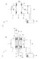
そして磁界共鳴方式は、代表的には、図3の(1)図に示したように、中継コイル2を使用した非接触給電装置1について、適用,実施されていた。
すなわち、この非接触給電装置1では、送電コイル3と受電コイル4間のエアギャップGの磁路に、共振回路5を構成する中継コイル2が、送電コイル3側と受電コイル4側とに、それぞれ配設されている。この両共振回路5は、送電コイル3等の送電側回路6や受電コイル4等の受電側回路7から、電気的に絶縁されており、独立した別回路よりなる。そして、エアギャップGの磁路に励磁無効電力を供給するようになっている。図中8は、共振用のコンデンサである。
そして磁界共鳴方式として、両共振回路5の共振周波数が等しく設定されており、共鳴コイルとして中継コイル2間で磁場が結合すると共に、送電側回路6の高周波電源9の電源周波数が、この共振周波数と揃えられている。<Conventional technology>
In this type of non-contact power feeding device, there is a great need for widening the air gap and increasing the air gap in view of convenience during power feeding. As part of this, research and development of the magnetic field resonance method has progressed. ing.
The magnetic field resonance method is typically applied and implemented for the non-contact
That is, in the non-contact
And as a magnetic field resonance system, the resonance frequency of both the resonance circuits 5 is set equally, a magnetic field couple | bonds between the
磁界共鳴方式は、このように中継コイル2を使用した図3の(1)図の非接触給電装置1について、適用,実施されるタイプが代表的である。
これに対し磁界共鳴方式は、中継コイル2を使用しない図3の(2)図に示した非接触給電装置10について、適用,実施するタイプも可能である。
すなわち、この非接触給電装置10では、送電側回路6について、送電コイル3と並列コンデンサ11が配されて、並列共振回路が形成されると共に、受電側回路7について、受電コイル4と並列コンデンサ12が配されて、並列共振回路が形成されている。
そしてこのタイプでは、磁界共鳴方式として、送電コイル3と受電コイル4が共鳴コイルとして用いられ、両並列共振回路の共振周波数が等しく設定されると共に、送電側回路6の高周波電源9の電源周波数が、この共振周波数と揃えられている。図中13,14は、フェライトコア等の磁心コア、Lは負荷である。
そして磁界共鳴方式を、図3の(2)図の非接触給電装置10に適用,実施したタイプは、図3の(1)図の非接触給電装置1に適用,実施したタイプに比し、抵抗値減少等により、より大きな電力供給が可能となるという利点がある。なお、大きなエアギャップG化に伴う、電磁結合の結合係数Kの低下は、コイルのQ値で補うことが可能であり、送電コイル3と受電コイル4の相互インダクタンスよりはるかに小さな抵抗分を有する送電コイル3や受電コイル4を採用することによって、コイル間効率維持が可能である。The magnetic field resonance method is typically applied and implemented with respect to the non-contact
On the other hand, the magnetic field resonance method can be applied to and implemented in the non-contact
That is, in the non-contact
In this type, as the magnetic field resonance method, the
The magnetic resonance method is applied to and implemented in the non-contact
磁界共鳴方式を図3の(1)図の非接触給電装置1に適用,実施したタイプとしては、例えば、次の特許文献1が挙げられる。
図3の(2)図に示した非接触給電装置10については、例えば、同特許文献1中の背景技術欄を参照。
For the non-contact
《問題点》
ところで、このような従来の磁界共鳴方式の非接触給電装置10については、次の課題が指摘されていた。
磁界共鳴方式は、エアギャップG拡大を可能とし、例えば送電コイル3と受電コイル4間の電磁結合の結合係数Kが0.1以下となる、大きなエアギャップGのもとでの非接触給電を可能とする。しかしながら、送電コイル3を励磁する励磁皮相電力が極めて大となり、大容量の高周波電源9を必要とし、コスト負担が過大となる、という問題が指摘されていた。
例えば、図3の(2)図の非接触給電装置10についてシミュレーションすると、K値が0.05の場合、受電側回路7に2kW程度(出力電圧V2420V×5A)の電力供給を行おうとすると、送電側回路6の励磁皮相電力は、130kVAを超える大きさとなる(1.4kV×96A)。
送電コイル3への入力電圧V1は、1.4kVを越える高電圧を要し、これを送電側回路6の共振回路で作り出すことになる。結局、この高電圧を、高周波電源9やトランスにて供給することが必要となる。このように、送電コイル3と受電コイル4を共鳴コイルとして用いるタイプの磁界共鳴方式については、高圧で大容量のインバーター電源や昇圧トランスが必要となり、電源装置がコスト高となる、という問題が指摘されていた。"problem"
By the way, the following subject was pointed out about such a conventional magnetic resonance type non-contact
The magnetic field resonance method enables the air gap G to be enlarged. For example, non-contact power feeding under a large air gap G in which the coupling coefficient K of electromagnetic coupling between the
For example, when simulating the non-contact
The input voltage V1 to the
《本発明について》
本発明の磁界共鳴方式の非接触給電装置は、このような実情に鑑み、上述した従来技術の課題を解決すべくなされたものである。
そして本発明は、第1に、高圧で大容量の電源装置を用いることなく、第2に、エアギャップ拡大や大電力供給が実現される、磁界共鳴方式の非接触給電装置を提案することを、目的とする。<< About the present invention >>
In view of such a situation, the magnetic field resonance type non-contact power feeding device of the present invention has been made to solve the above-described problems of the prior art.
The present invention proposes, firstly, a magnetic resonance type non-contact power feeding device that realizes expansion of an air gap and large power supply without using a high-voltage, large-capacity power supply device. And aim.
《請求項について》
このような課題を解決する本発明の技術的手段は、特許請求の範囲に記載したように、次のとおりである。
この磁界共鳴方式の非接触給電装置は、電磁誘導の相互誘導作用に基づき、送電側回路の送電コイルから受電側回路の受電コイルに、エアギャップを存し非接触で近接対応位置しつつ電力を供給する。
そして該送電側回路について、該送電コイルと並列コンデンサが配されて、並列共振回路が形成されると共に、該受電側回路について、該受電コイルと並列コンデンサが配されて、並列共振回路が形成されている。
そして、両該並列共振回路の共振周波数が等しく設定されると共に、該送電側回路の高周波電源の電源周波数が、該共振周波数と揃えられている。該送電側回路は、該高周波電源側の回路部分と、該並列コンデンサや送電コイル側の回路部分とが、電界結合用コンデンサによる電界結合によって接続されている。<About Claim>
The technical means of the present invention for solving such a problem is as follows, as described in the claims.
This magnetic resonance type non-contact power feeding device is based on the mutual induction action of electromagnetic induction, and power is supplied from the power transmission coil of the power transmission side circuit to the power reception coil of the power reception side circuit in a non-contact proximity corresponding position. Supply.
For the power transmission side circuit, the power transmission coil and a parallel capacitor are arranged to form a parallel resonance circuit, and for the power reception side circuit, the power reception coil and a parallel capacitor are arranged to form a parallel resonance circuit. ing.
The resonance frequencies of both the parallel resonance circuits are set to be equal, and the power supply frequency of the high frequency power supply of the power transmission side circuit is aligned with the resonance frequency. In the power transmission side circuit, the circuit portion on the high frequency power source side and the circuit portion on the parallel capacitor or power transmission coil side are connected by electric field coupling using a field coupling capacitor.
すなわち、該送電コイルの両端は、それぞれ、該並列コンデンサとの両接続点を経由して、両該電界結合用コンデンサの一方の電極側に、直列接続されている。両該電界結合用コンデンサの他方の電極側は、それぞれ、該高周波電源の一端側と他端側に、直列接続されている。
そして、両該電界結合用コンデンサは、該共振周波数と等しく設定された共振周波数で該送電コイルと共振することによって、昇圧機能を発揮し、該高周波電源側の回路部分を低圧に保持しつつ、該送電コイル側の回路部分を高圧化すること、を特徴とする。That is, both ends of the power transmission coil are connected in series to one electrode side of both of the electric field coupling capacitors via both connection points with the parallel capacitor. The other electrode sides of the electric field coupling capacitors are connected in series to one end side and the other end side of the high-frequency power source, respectively.
Then, both the electric field coupling capacitors resonate with the power transmission coil at a resonance frequency set equal to the resonance frequency, thereby exhibiting a boost function, while maintaining the circuit portion on the high frequency power supply side at a low pressure, The circuit portion on the power transmission coil side is increased in pressure.
《作用等について》
本発明は、このような手段よりなるので、次のようになる。
(1)非接触給電装置では、受電コイルが送電コイルにエアギャップを存し近接対応位置しつつ、電力が供給される。
(2)給電に際しては、送電コイルに通電されて磁束が形成され、エアギャップに磁路が形成される。
(3)このように、誘起された磁界を利用し、電磁誘導の相互誘導作用に基づき、送電コイル側から受電コイル側へと電力が供給される。
(4)さて、送電側回路では送電コイルと並列コンデンサにより、受電側回路では受電コイルと並列コンデンサにより、並列共振回路が形成されている。これと共に、両共振周波数,高周波電源の電源周波数等が揃えられた、磁界共鳴方式よりなる。
(5)このように、送電コイルと受電コイルが、共鳴コイルとして用いられている。そしてエアギャップ拡大に鑑み、送電コイルへの励磁皮相電力が大きく、大なる入力電圧と電流を要する。
(6)そこでまず、共振回路で大電流が得られるから、電源装置側は小電流,小容量のまま、送電コイル側の大電力化が実現される。
(7)これと共に、送電側回路の高周波電源側と送電コイル等側間を、電界結合用コンデンサにて接続してなり、その昇圧機能により、高周波電源側を低圧に保持しつつ、送電コイル等側が高圧化される。電源装置側は低圧,小容量のまま、送電コイル側の高圧化が実現される。
(8)勿論、磁界共鳴方式よりなるので、エアギャップ拡大も実現される。又、エアギャップに独立した共振回路を設けないので、その分、大きな電力供給が可能となる。
(9)なお、送電側回路の高周波電源を絶縁トランスを介して接続すると、コモンモード電流が削減され、外部放射される不要電磁波が低減される。
(10)さてそこで、本発明の磁界共鳴方式の非接触給電装置は、次の効果を発揮する。<About the action>
Since the present invention comprises such means, the following is achieved.
(1) In the non-contact power feeding device, power is supplied while the power receiving coil is located close to the power transmitting coil with an air gap.
(2) During power feeding, a power transmission coil is energized to form a magnetic flux, and a magnetic path is formed in the air gap.
(3) Thus, electric power is supplied from the power transmission coil side to the power reception coil side based on the mutual induction effect of electromagnetic induction using the induced magnetic field.
(4) A parallel resonance circuit is formed by a power transmission coil and a parallel capacitor in the power transmission side circuit, and a power reception coil and a parallel capacitor in the power reception side circuit. Along with this, the magnetic resonance method is used in which both the resonance frequencies, the power supply frequency of the high frequency power supply, etc. are arranged.
(5) Thus, the power transmission coil and the power reception coil are used as resonance coils. In view of the expansion of the air gap, the excitation apparent power to the power transmission coil is large and requires a large input voltage and current.
(6) Therefore, first, since a large current is obtained by the resonance circuit, a large power can be realized on the power transmission coil side while the power supply device side has a small current and a small capacity.
(7) Along with this, the high frequency power supply side of the power transmission side circuit and the power transmission coil side are connected by an electric field coupling capacitor. The side is pressurized. High voltage on the power transmission coil side is realized while the power supply side remains low pressure and small capacity.
(8) Of course, since the magnetic resonance method is used, the air gap can be enlarged. In addition, since an independent resonance circuit is not provided in the air gap, a large amount of power can be supplied accordingly.
(9) When the high-frequency power source of the power transmission side circuit is connected via an insulating transformer, the common mode current is reduced and unnecessary electromagnetic waves radiated to the outside are reduced.
(10) Now, the magnetic resonance type non-contact power feeding device of the present invention exhibits the following effects.
《第1の効果》
第1に、高圧で大容量の電源装置を用いることなく、送電コイル電圧を高めることができる。
この磁界共鳴方式の非接触給電装置は、送電コイルと受電コイルを共鳴コイルとして用いるタイプよりなり、エアギャップ拡大のため送電コイルに大なる励磁皮相電力を要する。そこで本発明では、送電側回路の高周波電源側に対し送電コイル等側を、コンデンサによる電界結合によって接続し、もって高周波電源側を低圧に保持しつつ、送電コイル等側を高圧化する。これと共に、送電コイルに対して並列に共振コンデンサを接続し、もって、高周波電源側を小容量に保持しつつ、送電コイル等側を大電力化する。
従って、前述したこの種従来技術のように、高圧で大容量のインバーター電源やトランスを要し、電源装置がコスト高となる、という問題は解消される。本発明では、高周波電源の高圧化,大容量化を要することなく、トランスによる昇圧,高圧化も要することもなく、送電コイル高圧化を実施可能である。電源装置側は、低圧,小容量のまま給電すればよく、大幅なコスト低減が実現される。<< First effect >>
First, it is possible to increase the power transmission coil voltage without using a high-voltage and large-capacity power supply device.
This magnetic resonance type non-contact power supply apparatus is of a type that uses a power transmission coil and a power reception coil as resonance coils, and requires a large excitation apparent power in the power transmission coil in order to widen the air gap. Therefore, in the present invention, the power transmission coil or the like side is connected to the high frequency power source side of the power transmission side circuit by electric field coupling using a capacitor, and the power transmission coil or the like side is increased in pressure while the high frequency power supply side is held at a low pressure. At the same time, a resonance capacitor is connected in parallel to the power transmission coil, so that the power of the power transmission coil and the like is increased while the high frequency power supply side is held at a small capacity.
Therefore, the problem that a high-voltage, large-capacity inverter power supply or transformer is required as in the above-described prior art, and the cost of the power supply device is solved. In the present invention, it is possible to increase the transmission coil voltage without increasing the voltage and capacity of the high-frequency power source, and without increasing the voltage and voltage with a transformer. The power supply side only needs to be fed with low voltage and small capacity, and a significant cost reduction is realized.
《第2の効果》
第2に、もってエアギャップ拡大や、大電力供給が実現される。本発明の磁界共鳴方式の非接触給電装置は、送電コイルと受電コイルを共鳴コイルとして用いるタイプよりなる。
そこでまず、磁界共鳴方式の特徴を活かし、エアギャップ拡大・大エアギャップ化が実現され、給電時の利便性が向上する。これと共に、前述した中継コイルを使用したタイプの磁界共鳴方式の非接触給電装置に比し、より大きな電力供給が可能となる。<< Second effect >>
Second, widening of the air gap and high power supply are realized. The magnetic resonance type non-contact power feeding device of the present invention is of a type that uses a power transmission coil and a power reception coil as resonance coils.
First, taking advantage of the characteristics of the magnetic field resonance method, an air gap is enlarged and a large air gap is realized, and convenience during power feeding is improved. At the same time, it is possible to supply a larger amount of power as compared with the magnetic resonance type non-contact power feeding device using the relay coil described above.
このように、この種従来例に存した課題がすべて解決される等、本発明の発揮する効果は、顕著にして大なるものがある。 As described above, the effects exerted by the present invention are remarkably large, such as all the problems existing in this type of conventional example are solved.
以下、本発明を実施するための形態について、詳細に説明する。
《非接触給電装置15について》
まず、本発明の前提となる非接触給電装置15について、図4,図1,図2の(1)図等を参照して、一般的に説明する。
非接触給電装置15は、電磁誘導の相互誘導作用に基づき、送電側回路6の送電コイル3から受電側回路7の受電コイル4に、エアギャップGを存し非接触で近接対応位置しつつ、電力を供給する。
送電側回路6は、地上A側に定置配設されており、受電側回路7は車輌B等の移動体側に搭載されている。Hereinafter, embodiments for carrying out the present invention will be described in detail.
<< About the non-contact
First, the non-contact
The non-contact
The power
このような非接触給電装置15について、更に詳述する。まず、給電側,トラック側,1次側の送電側回路6は、給電スタンドC等の給電エリアにおいて、地面,路面,床面,その他の地上A側に、定置配置されている。
これに対し、受電側,ピックアップ側,2次側の受電側回路7は、電気自動車(EV車)や電車等の車輌B,その他の移動体側に搭載されている。受電側回路7は、駆動用の他、非駆動用としても利用可能であり、図4中に示したように、車載のバッテリー16に接続されるのが代表的であるが、図1,図2の(1)図中に示したように、各種負荷Lに直接接続される場合もある。
そして、送電側回路6の送電コイル3と受電側回路7の受電コイル4とは、給電に際し数10mm〜数100mm、例えば50mm〜150mm程度の僅かな間隙空間であるエアギャップGを存しつつ、非接触で近接して対応位置される。
給電に際しては、図示のように受電コイル4が、定置された送電コイル3に対し、上側等から対応位置して停止,駐車される停止給電方式が代表的であり、停止給電方式の場合は、送電コイル3と受電コイル4とは、上下等で対をなしうる対称構造よりなる。これに対し、受電コイル4が送電コイル3上等を低速走行しつつ給電を行う移動給電方式も、可能であり、移動給電方式の1例としては、高速道路上で走行中の電気自動車に対して、給電する例が挙げられる。Such a non-contact
On the other hand, the power receiving
The
In the case of power feeding, a stop power feeding method in which the
送電側回路6の送電コイル3は、高周波電源9に接続されている。高周波電源9は、周波数等交換用のインバーター電源よりなり、例えば数kHz〜数10kHz、更には数10kHz〜数100kHz程度の高周波交流を、給電交流,励磁電流として送電コイル3に向けて通電する。図1の送電側回路6中、17はチョークコイル、11は、送電コイル3との並列共振用の並列コンデンサである。
受電側回路7の受電コイル4は、図4の例では、バッテリー16に接続可能となっており、給電により充電されたバッテリー16にて走行用のモータ18が駆動されるが、図1,図2の(1)図の例では、その他の負荷Lに電力供給される。図4中19は、交流を直流に変換するコンバータ(整流部や平滑部)、20は、直流を交流に変換するインバータであり、図1の受電側回路7中、12は受電コイル4との並列共振用の並列コンデンサである。
送電コイル3および受電コイル4は、渦巻状に巻回された扁平フラット構造をなしている。すなわち、絶縁被覆されたコイル導線が、同一平面において並列化された平行位置関係を維持しつつ、円形や方形の渦巻状に複数回巻回ターンされ、もって全体的に凹凸のない平坦で肉厚の薄い扁平フラット構造をなすと共に、環状,略フランジ状をなしている。
又、送電コイル3や受電コイル4は、それぞれ外側に、フェライトコア等の磁心コア13や14を備えている(図3を参照)。磁心コア13,14は強磁性体よりなり、フラットな平状,環状,略フランジ状の扁平フラット構造をなし、送電コイル3や受電コイル4に対し、若干大きな表面積よりなると共に同心に配置されている。そして、コイルインダクタンスを増し電磁結合を強化すると共に、形成磁束を誘導,収集,方向付けする。The
In the example of FIG. 4, the
The
The
電磁誘導の相互誘導作用については、次のとおり。給電に際し、エアギャップGを介して近接対応位置する送電コイル3と受電コイル4間において、送電コイル3での磁束形成により、受電コイル4に誘導起電力を生成させ、もって送電コイル3から受電コイル4に電力を供給することは、公知公用である。
すなわち、図1,図2の(1)図に示したように、送電側回路6の送電コイル3に、高周波電源9から給電交流,励磁電流を印加,通電することにより、自己誘導起電力が発生して、磁界が送電コイル3の周囲に生じ、磁束φがコイル面に対して直角方向に形成される。
そして、このように形成された磁束φが、受電側回路7の受電コイル4を貫き鎖交することにより、誘導起電力が生成されて磁界が形成される。このように、誘起された磁界を利用して電力が送受され、数kW以上そして数10kW〜数100kW程度の電力供給が可能である。送電コイル3側の磁束φの磁気回路と、受電コイル4側の磁束φの磁気回路とは、相互間にも磁束φの磁気回路つまり磁路が形成されて、電磁結合される。
非接触給電装置15では、このような電磁誘導の相互誘導作用に基づき、非接触給電が行われる。非接触給電装置15について、一般的説明は以上のとおり。The mutual induction effect of electromagnetic induction is as follows. When power is fed, an induced electromotive force is generated in the
That is, as shown in FIG. 1 and FIG. 2 (1), a self-induced electromotive force is generated by applying and supplying a feeding AC current and an exciting current from the high-
And the magnetic flux (phi) formed in this way penetrates the
The non-contact
《本発明の概要》
以下、本発明の磁界共鳴方式の非接触給電装置15について、図1,図2を参照して説明する。まず、本発明の概要については、次のとおり。
この非接触給電装置15では、送電側回路6について、送電コイル3と並列に並列コンデンサ11が配されて、並列共振回路が形成されると共に、受電側回路7について、受電コイル4と並列に並列コンデンサ12が配されて、並列共振回路が形成されている。
そして磁界共鳴方式よりなり、両並列共振回路の共振周波数が等しく設定されると共に、送電側回路6の高周波電源9の電源周波数が、共振周波数と揃えられている。
そして本発明では、送電側回路6は、高周波電源9側の回路部分と、並列コンデンサ11や送電コイル3側の回路部分とが、コンデンサ21,22による電界結合によって、接続されている。この電界結合用コンデンサ21,22は昇圧機能を発揮し、高周波電源9側の回路部分を低圧に保持しつつ、送電コイル3等側の回路部分を高圧化する。
もって、共振による送電コイル3の大電流化と、このような高圧化により、送電コイル3の励磁皮相電力が大となる。
本発明の概要については、以上のとおり。以下、このような本発明について、更に詳述する。<< Outline of the Invention >>
A magnetic resonance type non-contact
In the non-contact
The resonance frequency of the both parallel resonance circuits is set to be equal, and the power frequency of the high
In the present invention, in the power
Therefore, the apparent current power of the
The outline of the present invention is as described above. Hereinafter, the present invention will be described in detail.
《磁界共鳴方式について》
まず、磁界共鳴方式について図2等を参照して説明する。非接触給電方式としては、前述したように、電磁誘導の相互誘導作用を利用するものが知られているが、近年、これに加え磁界共鳴方式を併用する技術が、注目されている。
磁界共鳴方式では、相互磁束φで電磁結合すると共に互いに同一の共振周波数を有する送電コイル3側と受電コイル4側とを、エアギャップGを存して近接対応位置させると共に、共振周波数と同一周波数の励磁電流を流す。これにより、送電コイル3と受電コイル4間で共鳴現象が生じ、もって更なるエアギャップG拡大が実現されつつ、給電が行われるようになる。
そして、本発明の非接触給電装置15では、まず前提として、送電側回路6について、送電コイル3と並列コンデンサ11にて並列共振回路が形成されると共に、受電側回路7について、受電コイル4と並列コンデンサ12にて、並列共振回路が形成される。
これと共に、本発明が前提とする磁界共鳴方式では、送電側回路6の並列共振回路の共振周波数と、受電側回路7の並列共振回路の共振周波数とが、等しく設定されると共に、送電側回路6の高周波電源9の電源周波数も、これと揃えられている。
磁界共鳴方式については、以上のとおり。About magnetic resonance method
First, the magnetic field resonance method will be described with reference to FIG. As described above, as a non-contact power supply method, one using the mutual induction action of electromagnetic induction is known, but in recent years, a technique using the magnetic field resonance method in addition to this has attracted attention.
In the magnetic field resonance method, the
In the non-contact
At the same time, in the magnetic field resonance method assumed by the present invention, the resonance frequency of the parallel resonance circuit of the power
The magnetic resonance method is as described above.
《周波数設定について》
次に、上述した周波数の設定について、図2等を参照して説明する。まず、送電側回路6の並列共振回路の共振周波数f1(Hz)は、送電コイル3の自己インダクタンスL1(H)と、並列コンデンサ11のキャパシタンスC1(F)とによって定まる。
又、受電側回路7の並列共振回路の共振周波数f2(Hz)は、受電コイル4の自己インダクタンスL2(H)と、並列コンデンサ12のキャパシタンスC2(F)とによって定まる。
そして、この両共振周波数f1,f2が等しくなるように、設定される。共振周波数f1,f2は、次の数式1,2にて与えられる。<About frequency setting>
Next, the frequency setting described above will be described with reference to FIG. First, the resonance frequency f1 (Hz) of the parallel resonance circuit of the power
The resonance frequency f2 (Hz) of the parallel resonance circuit of the power receiving
The resonance frequencies f1 and f2 are set to be equal. The resonance frequencies f1 and f2 are given by the following

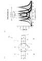
具体的な周波数設定については、次のとおり。まず前提として、送電側回路6の送電コイル3への入力電圧V1に対する、受電側回路7の受電コイル4の出力電圧V2の周波数応答は、図2の(2)図のような比率となり、双峰特性を示す。
すなわち、送電コイル3と受電コイル4間のエアギャップG距離が、過度に大きい場合、出力電圧V2の周波数応答は単峰特性を示す。これに対し、エアギャップG距離が給電可能に接近すると、周波数応答は、電磁結合係数Kに対応しつつ図示のように双峰特性を示す。
なお結合係数Kは、送電コイル3と受電コイル4間の電磁結合の結合度合を表し、次の数式3にて与えられる。M(H)は相互インダクタンスであり、K値は、エアギャップG距離の大小に比例して、0〜1間の値を取る。距離が離れると漏洩磁束が増加するので0に近づき、距離が近づくと1に近づき、漏洩磁束のない仮想状態では1となる。Specific frequency settings are as follows. First, as a premise, to the input voltages V1 to the
In other words, the air gap G the distance between the
The coupling coefficient K represents the degree of electromagnetic coupling between the
さて、図2の(2)図に示したように、受電コイル4の出力電圧V2の周波数応答は、双峰特性を示すが、その峰と峰の間の周波数差Δfの大小は、K値に比例する。エアギャップG距離が小さくなって、K値が大きくなると、広がり、エアギャップG距離が大きくなってK値が小さくなると、縮まる。
そして、テーマとする共振周波数f2の設定に際しては、特定の結合係数Kについて、このような双峰特性を示す両峰の周波数の中間の周波数とされる。受電コイル4側の共振周波数f2は、一方の峰の周波数と他方の峰の周波数との、中間の周波数に合わせられる。
そこで、送電コイル3側の共振周波数f1もこれに等しく設定され、高周波電源9の電源周波数も、これに揃えられる。これに対応して、送電コイル3や受電コイル4の自己インダクタンスL1,L2が調整される。
周波数設定については、以上のとおり。Now, as shown in (2) view of FIG. 2, the frequency response of the output voltage V2 of the
Then, when setting the resonance frequency f2 as a theme, the specific coupling coefficient K is set to an intermediate frequency between the frequencies of both peaks showing such a bimodal characteristic. The resonance frequency f2 of the
Therefore, the resonance frequency f1 of the
The frequency setting is as above.
《電界結合用コンデンサ21,22について》
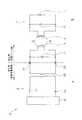
次に、電界結合用コンデンサ21,22について、図1を参照して説明する。送電側回路6は、高周波電源9側の回路部分と、並列共振回路を構成する送電コイル3および並列コンデンサ11の回路部分とが、電界結合用コンデンサ21,22によって接続されている。
すなわち、送電コイル3の両端は、それぞれ、並列コンデンサ11との両接続点を経由して、両電界結合用コンデンサ21,22の一方の電極側に、直列接続されている。これに対し、両電界結合用コンデンサ21,22の他方の電極側は、それぞれ、図示例では絶縁トランス23の2次側コイルの両端に、直列接続されている。
そして、電界結合用コンデンサ21,22は、それぞれ電極間に誘起される電気力線そして電界を利用して電力を送受するが、送電コイル3と共振することによって、昇圧機能を発揮する。
すなわち、両電界結合用コンデンサ21,22は、分圧しつつ送電コイル3と並列共振する(その共振周波数は、前述した共振周波数と等しく設定される)。もって送電側回路6について、高周波電源9側の回路部分を、高圧化,昇圧化することなく低圧に保持しつつ、送電コイル3および並列コンデンサ11側の回路部分を、並列コンデンサ11と共に高圧化する。
電界結合用コンデンサ21,22については、以上のとおり。<< About the electric
Next, the electric
That is, both ends of the
The electric
That is, both the electric
The electric
《絶縁トランス23等について》
次に、絶縁トランス23等について、図1を参照して説明する。送電側回路6は、上述したように低圧に保持される高周波電源9側の回路部分に関し、更に、絶縁トランス23が設けられている。高周波電源9側の回路部分と、上述した電界結合用コンデンサ21,22,並列コンデンサ11,送電コイル3等側の回路部分とが、絶縁トランス23を介して接続されている。
すなわち、絶縁トランス23の2次側コイルは、その一端が、一方の電界結合用コンデンサ21に直列接続され、その他端が、他方の電界結合用コンデンサ22に直列接続されている。これに対し、絶縁トランス23の1次側コイルは、その一端が、高周波電源9の一端側に、チョークコイル17を介して直列接続され、その他端が、高周波電源9の他端側に、コンデンサ24を介して直列接続されている。
そして絶縁トランス23は、高周波電源9側と送電コイル3側間を電気的に絶縁し、もってコモンモード電流を削減して、送電コイル3によって形成される磁界に基づく不要電磁波放射を、低減すべく機能する。
勿論、絶縁トランス23による変圧機能により、高周波電源9のインバータ電源を、適切な運転ポイントで運転するようにすることも可能であり、効率向上の一助ともなる。<
Next, the insulating
In other words, the secondary coil of the insulating
The
Of course, it is possible to operate the inverter power supply of the high-
なおチョークコイル17は、高周波電源9からの給電交流について、基本波以外の高調波成分を減衰せしめる。すなわち、高周波電源9としては、コスト面に優れた矩形波インバータが使用されることが多く、給電交流に高調波成分が含まれているので、並列コンデンサ11への流入をカットすべく、設けられている。
又、コンデンサ24は、絶縁トランス23に直流成分が流れ込むのをブロックする。すなわちコンデンサ24は、高周波電源9からの給電交流に含まれる直流成分が、絶縁トランス23に流れ込むのを阻止し、もって絶縁トランス23の性能劣化を防止する。
絶縁トランス23等については、以上のとおり。The
Further, the
The
《作用等》
本発明の磁界共鳴方式の非接触給電装置15は、以上説明したように構成されている。そこで、以下のようになる。
(1)非接触給電装置15では、車輌B等の移動体側に搭載された受電側回路7の受電コイル4が、地上A側に定置配置された送電側回路6の送電コイル3に対し、エアギャップGを存し非接触で近接対応位置しつつ、電力が供給される(図4等を参照)。《Action etc.》
The magnetic resonance type non-contact
(1) In the non-contact
(2)給電に際しては、まず送電側回路6において、送電コイル3が高周波電源9からの高周波交流を励磁電流として、通電される。そこで、送電コイル3に磁束φが形成され、もって、送電コイル3と受電コイル4間のエアギャップGに、磁束φの磁路が形成される(図2の(1)図等を参照)。 (2) When power is supplied, first, in the power
(3)このようにエアギャップGを介して、送電コイル3側と受電コイル4側間が電磁結合され、磁束φが受電コイル4を貫き鎖交することにより、誘導起電力が生成される。
非接触給電装置15では、このように誘起された磁界を利用し、電磁誘導の相互誘導作用に基づき、電力が送電側回路6から受電側回路7へと、供給される(図1,図2の(1)図を参照)。(3) In this way, the
In the non-contact
(4)ところで、この非接触給電装置15は、送電側回路6については送電コイル3と並列コンデンサ11により、受電側回路7については受電コイル4と並列コンデンサ12により、それぞれ並列共振回路が形成されている。
これと共に、この非接触給電装置15は磁界共鳴方式よりなり、両並列共振回路の共振周波数f1,f2、および送電側回路6の高周波電源9の電源周波数が、等しく揃えられ、送電コイル3の大電流化が達成されている(図1等を参照)。(4) By the way, this non-contact
At the same time, the non-contact
(5)さて、この磁界共鳴方式の非接触給電装置15は、送電コイル3と受電コイル4を共鳴コイルとして用いるタイプよりなる。そして、K値で言えば0.1以下となる大きなエアギャップG下で非接触給電が実施されるので、送電コイル3への励磁皮相電力が大きく、送電コイル3への入力電圧V1にも高電圧を要する。(5) The magnetic field resonance type non-contact
(6)そこで本発明では、送電側回路6について、高周波電源9側と送電コイル3等側との間を、電界結合用コンデンサ21,22にて、接続してなる(図1を参照)。
そして、この電界結合用コンデンサ21,22が昇圧機能を発揮し、送電側回路6の高周波電源9側を低圧に保持しつつ、送電コイル3等側を高圧化する。もって、高周波電源9の高圧化,大容量化や、トランスによる昇圧,高圧化を要することなく、電源装置側は低圧,小容量のまま、送電コイル3の高圧化が実現される。(6) Therefore, in the present invention, the power
The electric
(7)勿論、この非接触給電装置15は、送電コイル3と受電コイル4を共鳴コイルとして用いるタイプの磁界共鳴方式よりなるので、エアギャップGの拡大,大きなエアギャップGも実現される。
更に、この磁界共鳴方式は、エアギャップGについて、送電側回路6や受電側回路7とは独立した中継コイル2や共振回路5(図3の(1)図の従来技術を参照)を、設けないタイプよりなる。そこで、その分だけ抵抗値が減少される等により、受電側回路7に対し、より大きな電力供給が可能となる。(7) Of course, the non-contact
Further, this magnetic field resonance system is provided with the
(8)ところで図示例では、送電側回路6について、高周波電源9側と電界結合用コンデンサ21,22,並列コンデンサ11,送電コイル3等側とが、絶縁トランス23を介して、接続されている(図1を参照)。
そして絶縁トランス23は、高周波電源9側と送電コイル3側間を電気的に絶縁して、コモンモード電流を削減する。もって、送電コイル3そして受電コイル4間に形成される磁界に基づき外部放射される電磁波が、大きく低減されるので、非接触給電装置15の近隣周辺における電磁波障害発生の危険は、回避される。(8) By the way, in the example of illustration, about the power
And the
(9)なお、この明細書において、「共振周波数が等しく設定される」,「共振周波数と等しく揃えられる」,「共振周波数と揃えられる」,「両峰の周波数」,「両峰の周波数の中間の周波数」等の用語は、完全同一や完全中間を要求するものではない。
すなわち、これらの用語はより広い意味に、つまりその程度の周波数,その前後範囲の周波数を意味する概念として、把握される。なお、そのQ値が高ければ、その意味する周波数範囲は狭く把握され、Q値が低ければ、その意味する周波数範囲は広く把握される。つまり、これらの用語は、テーマとする共鳴を可能ならしめる範囲の周波数を意味すべく、把握される。
作用等については、以上のとおり。(9) In this specification, “resonance frequency is set equal”, “resonance frequency is equalized”, “resonance frequency is aligned”, “bimodal frequency”, “bimodal frequency” Terms such as “intermediate frequency” do not require perfect identity or perfect middle.
That is, these terms are understood in a broader sense, that is, as a concept that means a frequency of that degree and a frequency in the range before and after that. If the Q value is high, the frequency range that is meant is grasped narrowly, and if the Q value is low, the frequency range that is meant is widely grasped. That is, these terms are understood to mean frequencies in a range that enables thematic resonance.
As for the action, it is as above.
ここで、本発明の実施例について説明しておく。
本発明の非接触給電装置15を図1の回路について実施し、もって受電側回路7の負荷Lに対し、2kW程度の電力供給を行う場合について、シミュレーションした。
なお、K値=0.05、送電コイル3の自己インダクタンスL1=26.2(H)、受電コイル4の自己インダクタンスL2=18.2(H)、並列コンデンサ11のキャパシタンス=100n(F)、並列コンデンサ12のキャパシタンス=170n(F)、電界結合用コンデンサ21,22のキャパシタンス=50n(F)とした。(なお、電界結合用コンデンサ21,22のキャパシタンスは、このように同じ値に揃えなくてもよい。)Here, examples of the present invention will be described.
The non-contact
The K value = 0.05, the self-inductance L1 of the
このような前提条件下でシミュレーションした結果、次のデータが得られた。
・高周波電源9:
257V×10A=電源供給電力2.57kW
・絶縁トランス23の1次側コイル側:
260V×10A=皮相電力2.60kVA
・絶縁トランス23の2次側コイル 〜 電界結合用コンデンサ21,22の低圧側:
145V×10A=皮相電力1.45kVA
・電界結合用コンデンサ21,22の高圧側 〜 送電コイル3:
1.4kV×96A=皮相電力134.4kVA
・受電コイル4〜:
420V×40A=皮相電力16.8kVA
・負荷L:
420V×5A=有効電力2.1kW
このように、受電側回路7の負荷Lに対し、2kW程度の電力供給を実施する場合、つまり送電側回路6の送電コイル3に対し、1.4kV程度の入力電圧V1を要する場合でも、送電側回路6の絶縁トランス23側は145V程度の低電圧で済み、そして高周波電源9側は257V程度の低電圧で済んだ。このように、電源装置側が低電圧で済むことが裏付けられた。
実施例については、以上のとおり。As a result of simulation under such preconditions, the following data was obtained.
・ High frequency power supply 9:
257V × 10A = Power supply power 2.57kW
-Primary coil side of the insulation transformer 23:
260V × 10A = apparent power 2.60kVA
The secondary coil of the insulating
145V × 10A = apparent power 1.45kVA
・ High-voltage side of electric
1.4 kV × 96 A = apparent power 134.4 kVA
・ Receiving
420V × 40A = apparent power 16.8kVA
-Load L:
420 V x 5 A = active power 2.1 kW
Thus, even when the power supply of about 2 kW is performed to the load L of the power receiving
About an Example, it is as above.
1 非接触給電装置(従来例)
2 中継コイル
3 送電コイル
4 受電コイル
5 共振回路
6 送電側回路
7 受電側回路
8 コンデンサ
9 高周波電源
10 非接触給電装置(従来例)
11 並列コンデンサ
12 並列コンデンサ
13 磁心コア
14 磁心コア
15 非接触給電装置(本発明)
16 バッテリー
17 チョークコイル
18 モータ
19 コンバータ
20 インバータ
21 電界結合用コンデンサ
22 電界結合用コンデンサ
23 絶縁トランス
24 コンデンサ
A 地上
B 車輌
C 給電スタンド
G エアギャップ
L 負荷
V1入力電圧
V2出力電圧
φ 磁束
1 Non-contact power feeding device (conventional example)
DESCRIPTION OF
DESCRIPTION OF
16
Claims (1)
Translated fromJapanese該送電側回路について、該送電コイルと並列コンデンサが配されて、並列共振回路が形成されると共に、該受電側回路について、該受電コイルと並列コンデンサが配されて、並列共振回路が形成されており
両該並列共振回路の共振周波数が等しく設定されると共に、該送電側回路の高周波電源の電源周波数が、該共振周波数と揃えられており、
該送電側回路は、該高周波電源側の回路部分と、該並列コンデンサや送電コイル側の回路部分とが、電界結合用コンデンサによる電界結合によって接続され、
該送電コイルの両端は、それぞれ、該並列コンデンサとの両接続点を経由して、両該電界結合用コンデンサの一方の電極側に、直列接続されており、
両該電界結合用コンデンサの他方の電極側は、それぞれ、該高周波電源の一端側と他端側に、直列接続されており、
両該電界結合用コンデンサは、該共振周波数と等しく設定された共振周波数で該送電コイルと共振することによって、昇圧機能を発揮し、該高周波電源側の回路部分を低圧に保持しつつ、該送電コイル側の回路部分を高圧化すること、を特徴とする磁界共鳴方式の非接触給電装置。In a non-contact power feeding device that supplies electric power from a power transmission coil of a power transmission side circuit to a power reception coil of a power reception side circuit while maintaining an air gap and being in a non-contact proximity position based on the mutual induction action of electromagnetic induction.
For the power transmission side circuit, the power transmission coil and a parallel capacitor are arranged to form a parallel resonance circuit, and for the power reception side circuit, the power reception coil and a parallel capacitor are arranged to form a parallel resonance circuit. And the resonance frequency of both the parallel resonance circuits is set equal, and the power supply frequency of the high frequency power supply of the power transmission side circuit is aligned with the resonance frequency,
In the power transmission side circuit, the circuit portion on the high frequency power source side and the circuit portion on the parallel capacitor or power transmission coil side are connected by electric field coupling using a field coupling capacitor,
Both ends of the power transmission coil are connected in series to one electrode side of both the electric field coupling capacitors via both connection points with the parallel capacitor,
The other electrode sides of the electric field coupling capacitors are connected in series to one end side and the other end side of the high-frequency power source, respectively.
Both of the electric field coupling capacitors resonate with the power transmission coil at a resonance frequency set equal to the resonance frequency, thereby exhibiting a step-up function and maintaining the circuit portion on the high-frequency power source side at a low pressure. A magnetic resonance type non-contact power feeding device characterized in that a circuit portion on a coil side is increased in pressure.
Priority Applications (5)
| Application Number | Priority Date | Filing Date | Title |
|---|---|---|---|
| JP2011000719AJP5730587B2 (en) | 2011-01-05 | 2011-01-05 | Magnetic resonance type non-contact power feeding device |
| US13/228,035US20120169135A1 (en) | 2011-01-05 | 2011-09-08 | Non-contact power feeding apparatus of magnetic resonance method |
| EP11182363AEP2475062A2 (en) | 2011-01-05 | 2011-09-22 | Non-contact power feeding apparatus for implementing magnetic resonance method |
| KR1020110098728AKR101230211B1 (en) | 2011-01-05 | 2011-09-29 | Non-contact power feeding apparatus of magnetic resonance method |
| CN2011103276630ACN102593958A (en) | 2011-01-05 | 2011-10-20 | Non-contact power feeding apparatus of magnetic resonance method |
Applications Claiming Priority (1)
| Application Number | Priority Date | Filing Date | Title |
|---|---|---|---|
| JP2011000719AJP5730587B2 (en) | 2011-01-05 | 2011-01-05 | Magnetic resonance type non-contact power feeding device |
Publications (2)
| Publication Number | Publication Date |
|---|---|
| JP2012143106A JP2012143106A (en) | 2012-07-26 |
| JP5730587B2true JP5730587B2 (en) | 2015-06-10 |
Family
ID=44719431
Family Applications (1)
| Application Number | Title | Priority Date | Filing Date |
|---|---|---|---|
| JP2011000719AActiveJP5730587B2 (en) | 2011-01-05 | 2011-01-05 | Magnetic resonance type non-contact power feeding device |
Country Status (5)
| Country | Link |
|---|---|
| US (1) | US20120169135A1 (en) |
| EP (1) | EP2475062A2 (en) |
| JP (1) | JP5730587B2 (en) |
| KR (1) | KR101230211B1 (en) |
| CN (1) | CN102593958A (en) |
Families Citing this family (28)
| Publication number | Priority date | Publication date | Assignee | Title |
|---|---|---|---|---|
| JP5899490B2 (en)* | 2011-07-20 | 2016-04-06 | パナソニックIpマネジメント株式会社 | Contactless power supply system |
| EP2775590B1 (en)* | 2011-11-04 | 2018-07-11 | Panasonic Intellectual Property Management Co., Ltd. | Coil unit and contactless electric power transmission device |
| EP2848453B1 (en)* | 2012-05-09 | 2017-10-11 | Toyota Jidosha Kabushiki Kaisha | Vehicle comprising power reception coil |
| CN102856989A (en)* | 2012-07-26 | 2013-01-02 | 中国科学院电工研究所 | Resonant type wireless transmission device based on high-temperature superconducting material |
| JP2014033499A (en)* | 2012-08-01 | 2014-02-20 | Sharp Corp | Wireless power supply system, wireless power supply device, and wireless power receiving device |
| JP5958258B2 (en)* | 2012-10-10 | 2016-07-27 | トヨタ自動車株式会社 | Non-contact power supply system and control method thereof |
| WO2014087889A1 (en)* | 2012-12-07 | 2014-06-12 | 日産自動車株式会社 | Non-contact power supply apparatus and method for controlling same |
| CN103904757A (en)* | 2012-12-31 | 2014-07-02 | 比亚迪股份有限公司 | Wireless charging system of electric automobile |
| JP6155033B2 (en)* | 2013-01-31 | 2017-06-28 | 古河電気工業株式会社 | Wireless power feeder for vehicle |
| JP2014155375A (en)* | 2013-02-12 | 2014-08-25 | Nitto Denko Corp | Wireless power transmission device, supply power control method of wireless power transmission device and manufacturing method of wireless power transmission device |
| US9876535B2 (en)* | 2013-02-21 | 2018-01-23 | Qualcomm Incorporated | Modular inductive power transfer power supply and method of operation |
| JP6216966B2 (en)* | 2013-03-29 | 2017-10-25 | 株式会社エクォス・リサーチ | Power transmission system |
| DE102013212007B4 (en)* | 2013-06-25 | 2025-03-27 | Bayerische Motoren Werke Aktiengesellschaft | Electrical supply of a stationary vehicle |
| JP5622901B1 (en)* | 2013-07-29 | 2014-11-12 | 日東電工株式会社 | Wireless power transmission device and method for controlling power supply of wireless power transmission device |
| JP6170372B2 (en)* | 2013-08-09 | 2017-07-26 | 株式会社Soken | Blower unit for air conditioner |
| JP6057477B2 (en)* | 2014-10-15 | 2017-01-11 | 学校法人加計学園 岡山理科大学 | Non-contact power feeding device |
| JP5975555B1 (en)* | 2015-12-08 | 2016-08-23 | 株式会社eNFC | Transmission system, transmission apparatus, and transmission method |
| JP6643139B2 (en)* | 2016-02-23 | 2020-02-12 | 昭和飛行機工業株式会社 | Non-contact power supply device for underwater robots |
| JP6599265B2 (en)* | 2016-03-01 | 2019-10-30 | 昭和飛行機工業株式会社 | Non-contact power feeding device |
| JP6693556B2 (en)* | 2016-03-18 | 2020-05-13 | 株式会社村田製作所 | Wireless power supply system and power transmission device thereof |
| CN106300448A (en)* | 2016-10-11 | 2017-01-04 | 武汉大学 | One utilizes capacity coupled wireless electric energy transmission device |
| JP6622181B2 (en)* | 2016-12-27 | 2019-12-18 | 昭和飛行機工業株式会社 | Non-contact power supply device |
| WO2019043793A1 (en)* | 2017-08-29 | 2019-03-07 | 株式会社Fuji | Power transmission unit and non-contact feeding device |
| KR101873399B1 (en) | 2018-01-04 | 2018-07-02 | (주)그린파워 | Resonant Inductor of Wireless Power Transfer Apparatus and a method |
| US11843245B2 (en)* | 2018-03-02 | 2023-12-12 | Auckland Uniservices Limited | Wireless power transfer apparatus for wirelessly transferring power across an electrically conductive member |
| CN111016667B (en)* | 2019-12-03 | 2021-03-05 | 大同新成新材料股份有限公司 | Split type intelligent carbon sliding plate air passage processing equipment and processing method thereof |
| JP2021114833A (en) | 2020-01-17 | 2021-08-05 | 昭和飛行機工業株式会社 | Underwater non-contact power supply device |
| JP7391920B2 (en) | 2021-09-13 | 2023-12-05 | 株式会社東芝 | electronic circuits and methods |
Family Cites Families (19)
| Publication number | Priority date | Publication date | Assignee | Title |
|---|---|---|---|---|
| JPS56156018A (en)* | 1980-10-03 | 1981-12-02 | Nec Home Electronics Ltd | Intermittent boosting oscillator |
| US4796173A (en)* | 1988-02-01 | 1989-01-03 | General Electric Company | Low input voltage resonant power converter with high-voltage A.C. link |
| JP2004166384A (en)* | 2002-11-12 | 2004-06-10 | Sharp Corp | Electromagnetic coupling characteristic adjustment method in non-contact power supply system, power supply device, and non-contact power supply system |
| JP2006098170A (en)* | 2004-09-29 | 2006-04-13 | Soken Denki Kk | Partial discharge measuring system |
| JP2009089520A (en)* | 2007-09-28 | 2009-04-23 | Takenaka Komuten Co Ltd | Power supply system |
| JP4453741B2 (en)* | 2007-10-25 | 2010-04-21 | トヨタ自動車株式会社 | Electric vehicle and vehicle power supply device |
| US8339812B2 (en)* | 2007-12-07 | 2012-12-25 | Osram Gesellschaft Mit Beschraenkter Haftung | Resonant power converter with current doubler rectifier and related method |
| JP5490385B2 (en)* | 2008-08-04 | 2014-05-14 | 昭和飛行機工業株式会社 | Non-contact power feeding device |
| US20100045114A1 (en)* | 2008-08-20 | 2010-02-25 | Sample Alanson P | Adaptive wireless power transfer apparatus and method thereof |
| US7825537B2 (en)* | 2008-11-14 | 2010-11-02 | Harris Corporation | Inductive power transfer system and method |
| JP4759610B2 (en)* | 2008-12-01 | 2011-08-31 | 株式会社豊田自動織機 | Non-contact power transmission device |
| JP5437650B2 (en)* | 2009-01-30 | 2014-03-12 | 昭和飛行機工業株式会社 | Non-contact power feeding device |
| JP4849142B2 (en)* | 2009-02-27 | 2012-01-11 | ソニー株式会社 | Power supply device and power transmission system |
| JP5470965B2 (en)* | 2009-03-27 | 2014-04-16 | 日産自動車株式会社 | Power supply device |
| JP5510032B2 (en)* | 2009-05-14 | 2014-06-04 | 日産自動車株式会社 | Non-contact power feeding device |
| JP5375325B2 (en)* | 2009-05-18 | 2013-12-25 | トヨタ自動車株式会社 | Vehicle and contactless power supply system |
| JP2010280235A (en)* | 2009-06-02 | 2010-12-16 | Toyo Electric Mfg Co Ltd | Noncontact current collector |
| WO2011046227A2 (en)* | 2009-10-14 | 2011-04-21 | Panasonic Corporation | Electric machine and power supply system having battery pack |
| JP2011142769A (en)* | 2010-01-08 | 2011-07-21 | Toyota Central R&D Labs Inc | Method and device for transmitting magnetic resonance power |
- 2011
- 2011-01-05JPJP2011000719Apatent/JP5730587B2/enactiveActive
- 2011-09-08USUS13/228,035patent/US20120169135A1/ennot_activeAbandoned
- 2011-09-22EPEP11182363Apatent/EP2475062A2/ennot_activeWithdrawn
- 2011-09-29KRKR1020110098728Apatent/KR101230211B1/ennot_activeExpired - Fee Related
- 2011-10-20CNCN2011103276630Apatent/CN102593958A/enactivePending
Also Published As
| Publication number | Publication date |
|---|---|
| US20120169135A1 (en) | 2012-07-05 |
| KR20120079799A (en) | 2012-07-13 |
| JP2012143106A (en) | 2012-07-26 |
| CN102593958A (en) | 2012-07-18 |
| EP2475062A2 (en) | 2012-07-11 |
| KR101230211B1 (en) | 2013-02-05 |
Similar Documents
| Publication | Publication Date | Title |
|---|---|---|
| JP5730587B2 (en) | Magnetic resonance type non-contact power feeding device | |
| Panchal et al. | Review of static and dynamic wireless electric vehicle charging system | |
| Jeong et al. | Autotuning control system by variation of self-inductance for dynamic wireless EV charging with small air gap | |
| JP5016069B2 (en) | Power transmission system and vehicle power supply device | |
| Choi et al. | Six degrees of freedom mobile inductive power transfer by crossed dipole Tx and Rx coils | |
| US10202045B2 (en) | Vehicle with shielded power receiving coil | |
| Covic et al. | Modern trends in inductive power transfer for transportation applications | |
| JP2011258807A (en) | Non-contact power feeding device | |
| JP5075973B2 (en) | Non-contact power feeder with multi-pole coil structure | |
| JP2010173503A (en) | Non-contact power supply device | |
| Yilmaz et al. | General design requirements and analysis of roadbed inductive power transfer system for dynamic electric vehicle charging | |
| JP2010093180A (en) | Non-contact power supply | |
| Aziz et al. | Review of inductively coupled power transfer for electric vehicle charging | |
| JP5490385B2 (en) | Non-contact power feeding device | |
| EP3259623A1 (en) | Clover leaf and butterfly coil structures for flat wireless coupling profiles in wireless power transfer applications | |
| WO2011122249A1 (en) | Contactless power feeding apparatus and contactless power feeding method | |
| CN103826907A (en) | Power transmitting device, vehicle, and power transfer system | |
| WO2015040650A1 (en) | Contactless power transmission device | |
| WO2012001758A1 (en) | Non-contact electric power feeding device | |
| JP6305728B2 (en) | Coil unit and power transmission system | |
| JP2010035300A (en) | Non-contact power supply apparatus | |
| JP2010073885A (en) | Resonance coil and non-contact feeding system | |
| JP5384195B2 (en) | Non-contact power supply device | |
| JP6162609B2 (en) | Non-contact power feeding device | |
| JP2015195676A (en) | power transmission system |
Legal Events
| Date | Code | Title | Description |
|---|---|---|---|
| A621 | Written request for application examination | Free format text:JAPANESE INTERMEDIATE CODE: A621 Effective date:20130604 | |
| A131 | Notification of reasons for refusal | Free format text:JAPANESE INTERMEDIATE CODE: A131 Effective date:20140722 | |
| A521 | Request for written amendment filed | Free format text:JAPANESE INTERMEDIATE CODE: A523 Effective date:20140909 | |
| TRDD | Decision of grant or rejection written | ||
| A01 | Written decision to grant a patent or to grant a registration (utility model) | Free format text:JAPANESE INTERMEDIATE CODE: A01 Effective date:20150407 | |
| A61 | First payment of annual fees (during grant procedure) | Free format text:JAPANESE INTERMEDIATE CODE: A61 Effective date:20150408 | |
| R150 | Certificate of patent or registration of utility model | Ref document number:5730587 Country of ref document:JP Free format text:JAPANESE INTERMEDIATE CODE: R150 | |
| R250 | Receipt of annual fees | Free format text:JAPANESE INTERMEDIATE CODE: R250 | |
| R250 | Receipt of annual fees | Free format text:JAPANESE INTERMEDIATE CODE: R250 | |
| R250 | Receipt of annual fees | Free format text:JAPANESE INTERMEDIATE CODE: R250 | |
| R250 | Receipt of annual fees | Free format text:JAPANESE INTERMEDIATE CODE: R250 | |
| R250 | Receipt of annual fees | Free format text:JAPANESE INTERMEDIATE CODE: R250 | |
| R250 | Receipt of annual fees | Free format text:JAPANESE INTERMEDIATE CODE: R250 | |
| R250 | Receipt of annual fees | Free format text:JAPANESE INTERMEDIATE CODE: R250 | |
| S531 | Written request for registration of change of domicile | Free format text:JAPANESE INTERMEDIATE CODE: R313532 | |
| R350 | Written notification of registration of transfer | Free format text:JAPANESE INTERMEDIATE CODE: R350 |