JP5729873B2 - Dust collector - Google Patents
Dust collectorDownload PDFInfo
- Publication number
- JP5729873B2 JP5729873B2JP2011171930AJP2011171930AJP5729873B2JP 5729873 B2JP5729873 B2JP 5729873B2JP 2011171930 AJP2011171930 AJP 2011171930AJP 2011171930 AJP2011171930 AJP 2011171930AJP 5729873 B2JP5729873 B2JP 5729873B2
- Authority
- JP
- Japan
- Prior art keywords
- dust
- region
- storage area
- collector
- static electricity
- Prior art date
- Legal status (The legal status is an assumption and is not a legal conclusion. Google has not performed a legal analysis and makes no representation as to the accuracy of the status listed.)
- Active
Links
- 239000000428dustSubstances0.000titleclaimsdescription327
- 238000003860storageMethods0.000claimsdescription37
- 230000005611electricityEffects0.000claimsdescription31
- 230000003068static effectEffects0.000claimsdescription30
- 239000004020conductorSubstances0.000claimsdescription16
- 238000003754machiningMethods0.000claimsdescription4
- 238000010521absorption reactionMethods0.000claimsdescription2
- 239000002184metalSubstances0.000description12
- 230000007246mechanismEffects0.000description5
- 239000011347resinSubstances0.000description5
- 229920005989resinPolymers0.000description5
- 230000002411adverseEffects0.000description4
- 210000000078clawAnatomy0.000description4
- 230000033001locomotionEffects0.000description4
- OKTJSMMVPCPJKN-UHFFFAOYSA-NCarbonChemical compound[C]OKTJSMMVPCPJKN-UHFFFAOYSA-N0.000description3
- 230000000694effectsEffects0.000description3
- 230000005540biological transmissionEffects0.000description2
- 229910052799carbonInorganic materials0.000description2
- 238000006243chemical reactionMethods0.000description2
- 238000000151depositionMethods0.000description2
- 229920001971elastomerPolymers0.000description2
- 239000011888foilSubstances0.000description2
- 238000004898kneadingMethods0.000description2
- 206010044565TremorDiseases0.000description1
- 230000003139buffering effectEffects0.000description1
- 239000000470constituentSubstances0.000description1
- 238000005520cutting processMethods0.000description1
- 238000007599dischargingMethods0.000description1
- 238000005553drillingMethods0.000description1
- 239000000463materialSubstances0.000description1
- 238000000034methodMethods0.000description1
- 238000005498polishingMethods0.000description1
- 229920001084poly(chloroprene)Polymers0.000description1
Images


Classifications
- B—PERFORMING OPERATIONS; TRANSPORTING
- B23—MACHINE TOOLS; METAL-WORKING NOT OTHERWISE PROVIDED FOR
- B23Q—DETAILS, COMPONENTS, OR ACCESSORIES FOR MACHINE TOOLS, e.g. ARRANGEMENTS FOR COPYING OR CONTROLLING; MACHINE TOOLS IN GENERAL CHARACTERISED BY THE CONSTRUCTION OF PARTICULAR DETAILS OR COMPONENTS; COMBINATIONS OR ASSOCIATIONS OF METAL-WORKING MACHINES, NOT DIRECTED TO A PARTICULAR RESULT
- B23Q11/00—Accessories fitted to machine tools for keeping tools or parts of the machine in good working condition or for cooling work; Safety devices specially combined with or arranged in, or specially adapted for use in connection with, machine tools
- B23Q11/0042—Devices for removing chips
- B23Q11/0046—Devices for removing chips by sucking
- Y—GENERAL TAGGING OF NEW TECHNOLOGICAL DEVELOPMENTS; GENERAL TAGGING OF CROSS-SECTIONAL TECHNOLOGIES SPANNING OVER SEVERAL SECTIONS OF THE IPC; TECHNICAL SUBJECTS COVERED BY FORMER USPC CROSS-REFERENCE ART COLLECTIONS [XRACs] AND DIGESTS
- Y10—TECHNICAL SUBJECTS COVERED BY FORMER USPC
- Y10T—TECHNICAL SUBJECTS COVERED BY FORMER US CLASSIFICATION
- Y10T408/00—Cutting by use of rotating axially moving tool
- Y10T408/44—Cutting by use of rotating axially moving tool with means to apply transient, fluent medium to work or product
- Y10T408/45—Cutting by use of rotating axially moving tool with means to apply transient, fluent medium to work or product including Tool with duct
- Y10T408/453—Cutting by use of rotating axially moving tool with means to apply transient, fluent medium to work or product including Tool with duct and means to move gaseous fluid by application of vacuum
- Y—GENERAL TAGGING OF NEW TECHNOLOGICAL DEVELOPMENTS; GENERAL TAGGING OF CROSS-SECTIONAL TECHNOLOGIES SPANNING OVER SEVERAL SECTIONS OF THE IPC; TECHNICAL SUBJECTS COVERED BY FORMER USPC CROSS-REFERENCE ART COLLECTIONS [XRACs] AND DIGESTS
- Y10—TECHNICAL SUBJECTS COVERED BY FORMER USPC
- Y10T—TECHNICAL SUBJECTS COVERED BY FORMER US CLASSIFICATION
- Y10T408/00—Cutting by use of rotating axially moving tool
- Y10T408/50—Cutting by use of rotating axially moving tool with product handling or receiving means
Landscapes
- Engineering & Computer Science (AREA)
- Mechanical Engineering (AREA)
- Auxiliary Devices For Machine Tools (AREA)
- Percussive Tools And Related Accessories (AREA)
- Portable Power Tools In General (AREA)
Description
Translated fromJapanese本発明は、作業工具に取外し自在に取付けられ、加工作業時に生ずる粉塵を集塵するための集塵装置に関する。 The present invention relates to a dust collecting device that is detachably attached to a work tool and collects dust generated during a machining operation.
特開2006−102854号公報(特許文献1)は、加工作業時に発生する粉塵を集塵する集塵装置を備えた集塵ハンマドリルを開示している。集塵装置を備えた集塵ハンマドリルの場合、加工作業時に発生した粉塵を吸い込んで集塵容器に集塵する際に静電気が発生し、この静電気が集塵容器に帯電して作業者が集塵容器に触れたときに放電し、あるいは集塵ハンマドリルに搭載されたモータ制御用のコントローラ等の電気部品に対して悪影響を及ぼす可能性がある。このため、上記公報に記載の集塵ハンマドリルでは、ハウジングに一体状に組付けられたファンケーシングと集塵容器とをアース線で接続することによる静電気対策を行っている。 Japanese Patent Laying-Open No. 2006-102854 (Patent Document 1) discloses a dust collecting hammer drill including a dust collecting device that collects dust generated during a machining operation. In the case of a dust collecting hammer drill equipped with a dust collecting device, static electricity is generated when the dust generated during processing is sucked into the dust collecting container and collected in the dust collecting container. When the container is touched, it may be discharged, or it may adversely affect electric parts such as a motor control controller mounted on the dust collecting hammer drill. For this reason, the dust collecting hammer drill described in the above publication takes measures against static electricity by connecting the fan casing and the dust collecting container integrally assembled to the housing with a ground wire.
上記公報に記載の静電気対策は、あくまでも専用機としての対策に過ぎなかった。 The countermeasure against static electricity described in the above publication is only a countermeasure for a dedicated machine.
本発明は、上記に鑑みてなされたものであり、加工作業で発生した粉塵を合理的に集塵しつつ静電気の帯電を防止できる集塵装置を提供することをその目的とする。 The present invention has been made in view of the above, and an object of the present invention is to provide a dust collector capable of preventing electrostatic charge while rationally collecting dust generated in a processing operation.
上記課題を達成するため、本発明に係る好ましい形態の集塵装置は、作業工具に取外し自在に取付けられ、かつ作業工具と共に可搬とされる。そして、作業工具に装着された先端工具を駆動して被加工材に所定の加工作業を行う際に生ずる粉塵を集塵する。集塵装置は、先端工具に対応して、加工作業時の粉塵を吸引する吸塵領域と、吸塵領域で吸塵された粉塵を移送する粉塵移送領域と、粉塵移送領域に連通されて粉塵を収容する粉塵収容領域と、を有する。さらに集塵装置は、粉塵に帯電した静電気を逃がすアース部材を有する。この吸塵領域、粉塵移送領域および粉塵収容領域は、作業工具に対して一体状に着脱可能に構成されている。なお、電気の逃がし先としては、典型的には、集塵装置の構成部材のうち金属製部材が用いられる。また、本発明における「可搬」とは、作業工具と一体化され、加工作業を行うべく作業工具が操作されるとき、当該作業工具と共に移動される態様をいう。In order to achieve the above object, a dust collector of a preferred form according to the present invention is detachably attached to a work tool and is portable with the work tool. And the tip tool with which the work tool was mounted | worn is driven, and the dust which arises when performing a predetermined | prescribed processing operation to a workpiece is collected. Corresponding to the tip tool, the dust collector is connected to the dust suction area for sucking dust during processing, the dust transfer area for transferring dust sucked in the dust suction area, and the dust collecting area for receiving dust. A dust storage area. Furthermore, the dust collector has a grounding member that releases static electricity charged in the dust.The dust absorption area, the dust transfer area, and the dust storage area are configured to be detachable integrally with the work tool. Note that, as the escape destination of electricity, a metal member is typically used among the constituent members of the dust collector. Further, “portable” in the present invention refers to a mode in which the work tool is integrated with the work tool and is moved together with the work tool when the work tool is operated to perform a machining operation.
本発明の集塵装置は、作業工具に取外し自在に取付けられ、作業工具と共に可搬とされる。このため、作業工具による加工作業時において、集塵が必要とされる場合に当該作業工具に取付けて使用することができる。集塵装置は、加工作業で発生した粉塵を吸塵領域で吸引するとともに、粉塵移送領域を経て粉塵収容領域に収容する。これにより合理的な集塵作用が遂行される。集塵装置により粉塵を吸い込んで粉塵収容領域に収容する際、粉塵に帯電した静電気につき、アース部材を通じて逃がすことができる。これにより静電気による作業者への悪影響を回避することができる。 The dust collector of the present invention is detachably attached to a work tool and is portable with the work tool. For this reason, when dust collection is required at the time of working with the work tool, the work tool can be attached and used. The dust collecting device sucks dust generated in the processing operation in the dust suction region and stores it in the dust storage region through the dust transfer region. Thereby, a rational dust collecting action is performed. When the dust is sucked by the dust collector and stored in the dust storage area, static electricity charged in the dust can be released through the ground member. Thereby, it is possible to avoid an adverse effect on the worker due to static electricity.
本発明に係る集塵装置の更なる形態によれば、アース部材は、粉塵収容領域に収容された粉塵に帯電した静電気を逃がす構成とされる。この場合、アース部材は、粉塵収容領域に臨むように配置された導電材によって構成され、当該導電材を通じて粉塵に帯電した静電気を逃がす構成とすることが好ましい。なお、導電材としては、例えば樹脂にカーボンを練り込んだり、樹脂表面に金属箔を蒸着したりするなどの加工を施した導電性樹脂を好適に用いることが可能である。
この形態によれば、粉塵収容領域に収容された粉塵の静電気を逃がすことができ、合理的な静電気対策が実現される。According to the further form of the dust collector which concerns on this invention, an earth member is set as the structure which releases the static electricity electrically charged by the dust accommodated in the dust accommodating area | region. In this case, it is preferable that the ground member is made of a conductive material arranged so as to face the dust storage area and discharges static electricity charged in the dust through the conductive material. As the conductive material, for example, a conductive resin subjected to processing such as kneading carbon into a resin or depositing a metal foil on the resin surface can be suitably used.
According to this aspect, the static electricity of the dust stored in the dust storage area can be released, and a reasonable countermeasure against static electricity is realized.
本発明に係る集塵装置の更なる形態によれば、導電材は、集塵装置の導電性領域または当該集塵装置が取付けられた作業工具の導電性領域に電気的に接続され、粉塵収容領域に収容された粉塵に帯電した静電気を導電性領域に逃がす構成とされる。なお、本発明における「導電性領域」としては、集塵装置の集塵ファンを駆動するモータの金属製ハウジング、作業工具の先端工具を駆動するモータの金属製ハウジング、あるいは作業工具の外郭を構成する金属製ハウジング等を用いることが可能である。
この形態によれば、粉塵収容領域に収容された粉塵の静電気を集塵装置の導電性領域または当該集塵装置が取付けられた作業工具の導電性領域に逃がすことができる。According to the further form of the dust collector according to the present invention, the conductive material is electrically connected to the conductive region of the dust collector or the conductive region of the work tool to which the dust collector is attached, and contains dust. The static electricity charged in the dust accommodated in the area is released to the conductive area. The “conductive region” in the present invention is a metal housing of a motor that drives a dust collecting fan of a dust collector, a metal housing of a motor that drives a tip tool of a work tool, or an outline of a work tool. It is possible to use a metal housing or the like.
According to this aspect, static electricity of the dust stored in the dust storage area can be released to the conductive area of the dust collector or the conductive area of the work tool to which the dust collector is attached.
本発明に係る集塵装置の更なる形態によれば、粉塵収容領域を取付けるための粉塵収容領域取付部を有し、粉塵収容領域は、粉塵収容領域取付部に取外し自在に取付けられる。そして粉塵収容領域取付部には、導電性領域と導電材とを接続する介在部材が設けられる。介在部材は、粉塵収容領域が粉塵収容領域取付部に取付けられた状態において、導電性領域と導電材との電気的な接続と、粉塵収容領域と粉塵収容領域取付部の相互接触部の緩衝と、を兼務する構成とした。なお、本発明における「介在部材」としては、適度の弾性を有する導電性ゴムを用いることが好ましい。
さらに好ましくは、粉塵収容領域は、粉塵収容領域取付部に対して所定の支点周りに回動して着脱されるように構成されている。
さらに好ましくは、介在部材は、支点近傍に配置され、粉塵収容領域を支点周りに回動させて粉塵収容領域取付部に取り付ける動作に伴って、粉塵収容領域に弾発状に当接するように構成されている。
この形態によれば、介在部材が「電気的接続」と「緩衝」との2つの機能を兼務することで、部品点数が削減され、構造の簡素化を図ることができる。According to the further form of the dust collector which concerns on this invention, it has a dust accommodating area | region attaching part for attaching a dust accommodating area | region, and a dust accommodating area | region is attached to a dust accommodating area attaching part freely. The dust accommodating area mounting portion is provided with an interposition member that connects the conductive area and the conductive material. In the state where the dust storage area is attached to the dust storage area mounting portion, the interposition member is configured to electrically connect the conductive area and the conductive material, and to buffer the mutual contact portion between the dust storage area and the dust storage area mounting section. , And the configuration that concurrently serves. In addition, as the “intervening member” in the present invention, it is preferable to use conductive rubber having appropriate elasticity.
More preferably, the dust storage area is configured to be attached to and detached from the dust storage area mounting portion by rotating around a predetermined fulcrum.
More preferably, the interposition member is arranged in the vicinity of the fulcrum, and is configured to elastically abut against the dust storage area as the dust storage area is rotated around the fulcrum and attached to the dust storage area mounting portion. Has been.
According to this embodiment, the interposition member has two functions of “electrical connection” and “buffer”, thereby reducing the number of parts and simplifying the structure.
本発明に係る集塵装置の更なる形態によれば、粉塵収容領域は、粉塵フィルターが収容される粉塵容器本体と、粉塵フィルターを保持するフィルターホルダとを有する。そしてフィルターホルダが導電材によって形成されている。
この形態によれば、フィルターホルダを導電材により形成することで、集塵容器本体に集められる粉塵との接触領域を容易に確保できる。According to the further form of the dust collector which concerns on this invention, a dust accommodating area | region has a dust container main body in which a dust filter is accommodated, and a filter holder holding a dust filter. The filter holder is formed of a conductive material.
According to this embodiment, the contact area with the dust collected in the dust container main body can be easily secured by forming the filter holder with the conductive material.
本発明に係る集塵装置の更なる形態によれば、粉塵を吸引する吸引力を発生させる集塵ファンと当該集塵ファンを駆動する集塵モータとをさらに有する。
この形態によれば、作業工具側の動力を借りずに、集塵装置それ自体によって粉塵の集塵作用を遂行することができる。According to the further form of the dust collector which concerns on this invention, it further has a dust collector fan which generate | occur | produces the suction | attraction force which attracts | sucks dust, and a dust collector motor which drives the said dust collector fan.
According to this form, the dust collecting action of the dust can be performed by the dust collector itself without borrowing the power on the work tool side.
本発明に係る集塵装置の更なる形態によれば、集塵モータの外郭を構成する外郭部材が静電気を逃がす静電気収集領域として定められている。
この形態によれば、集塵装置に備えられた部材を静電気の逃がし先として利用することができ、合理的である。According to the further form of the dust collector according to the present invention, the outer member constituting the outer shell of the dust collecting motor is defined as a static electricity collecting region for releasing static electricity.
According to this embodiment, the member provided in the dust collector can be used as a static electricity release destination, which is reasonable.
本発明の更なる形態では、請求項1〜7のいずれかに記載の集塵装置が取付けられた作業工具が構成される。これにより、粉塵に帯電した静電気につき、アース部材を通じて逃がすことが可能な集塵装置を備えた作業工具を提供することができる。 In the further form of this invention, the work tool to which the dust collector in any one of Claims 1-7 is attached is comprised. As a result, it is possible to provide a work tool including a dust collecting device capable of releasing static electricity charged in dust through the ground member.
本発明によれば、加工作業で発生した粉塵を合理的に集塵しつつ静電気の帯電を防止できる集塵装置が提供されることとなった。 According to the present invention, a dust collector capable of preventing electrostatic charge while rationally collecting dust generated in a processing operation is provided.
以下、本発明の実施形態につき、図1〜図5を参照しつつ詳細に説明する。本実施の形態は、作業工具の一例として充電式のハンマドリルを用いて説明する。図1に示すように、本実施形態のハンマドリル101は、概括的に見て、ハンマドリル101の外郭を形成する作業工具本体としての本体部103と、当該本体部103の先端領域(図示左側)にツールホルダ117を介して着脱自在に取付けられるハンマビット119と、本体部103のハンマビット119の反対側に連接されたハンドグリップ109とを主体として構成されている。ハンマビット119は、ツールホルダ117によってその長軸方向への相対的な往復動が可能に、かつその周方向への相対的な回動が規制された状態で保持される。ハンマビット119は、本発明における「先端工具」に対応する。なお説明の便宜上、ハンマビット119側を前、ハンドグリップ109側を後という。 Hereinafter, embodiments of the present invention will be described in detail with reference to FIGS. This embodiment will be described using a rechargeable hammer drill as an example of a work tool. As shown in FIG. 1, the
本体部103は、便宜上、図示を省略する駆動モータ、運動変換機構、打撃要素および動力伝達機構等の駆動機構部を収容する金属製の本体ハウジングを主体として構成される。ハンドグリップ109は、ハンマビット119の長軸方向と交差する上下方向に延在するとともに、その上端部と下端部が本体部103に対してそれぞれ連接され、これによりループ状ハンドル(D形ハンドル)を構成している。ハンドグリップ109の下端部には、バッテリ装着部109Aが形成され、当該バッテリ装着部109Aには、駆動モータ111の電源となる充電式のバッテリパック110が着脱自在に装着されている。 For the sake of convenience, the
駆動モータの回転動力は、運動変換機構によって直線運動に適宜変換された上で打撃要素に伝達され、当該打撃要素を介してハンマビット119に対し長軸方向(図1における左右方向)への打撃力を加える。また、駆動モータの回転動力は、複数のギアを主体として構成される動力伝達機構によって適宜減速された上で最終軸としてのツールホルダ117を介してハンマビット119に伝達され、当該ハンマビット119が周方向に回転動作される。なお、駆動モータはハンドグリップ109に配置されたトリガ109aを作業者が引き操作することによって通電駆動される。 The rotational power of the drive motor is appropriately converted into a linear motion by a motion conversion mechanism and then transmitted to the striking element, and the
ハンマドリル101は、作業者が操作することで、ハンマビット119に対し長軸方向への打撃力のみを加えて被加工材にハツリ作業を行うハンマモード、長軸方向への打撃力と周方向への回転力とを加えて被加工材に穴開け作業を行うハンマドリルモード、周方向への回転力のみを加えて被加工材に穴明け作業を行うドリルモードの間で切替可能とされるが、このことについては周知の技術であり、かつまた本発明には直接的には関係しないため、その説明を省略する。 The
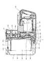
次に上記のように構成されたハンマドリル101に装着され、被加工材(例えば、コンクリート)に対する加工作業時に生じた粉塵を吸引して集塵するための集塵アタッチメント120につき、図2〜図5を参照して説明する。集塵アタッチメント120は、本発明における「集塵装置」に対応する。 Next, with respect to the
本実施の形態に係る集塵アタッチメント120は、集塵用動力源としての集塵モータ123及び集塵ファン125がそれぞれ装置本体としてのアタッチメント本体121に内蔵された吸引源内蔵方式であり、ハンマドリル101の本体部103を前方から後方に向かってハンマビット119の長軸方向へと水平状に移動させることによって、アタッチメント本体121が当該本体部103の前面下部領域のアタッチメント装着部に対して取り外し可能に取付けられる構成とされる。 The
集塵アタッチメント120は、図2に示すように、アタッチメント本体121、集塵モータ123、集塵ファン125、粉塵吸引部131、粉塵移送部137及び集塵容器141を主体として構成されている。集塵モータ123によって集塵ファン125が回転駆動されると、集塵容器141から粉塵移送部137の内部を通して粉塵吸引部131に吸引力が作用する。加工作業時に生じた粉塵は、粉塵吸引部131の吸引力で当該粉塵吸引部131の吸塵口133aから吸引されるとともに、粉塵移送部137を経て集塵容器141に集塵される。粉塵吸引部131は、本発明における「吸塵領域」に対応し、粉塵移送部137は、本発明における「粉塵移送領域」に対応し、集塵容器141は、本発明における「粉塵収容領域」に対応する。 As shown in FIG. 2, the
アタッチメント本体121は、粉塵移送部137の後端部から下方へと直線状に延在する垂直領域と、当該垂直領域の下端部から後方へと延在する水平領域とを有する側面視で略L形に形成されている。垂直領域は、集塵容器141が装着される容器取付部121Aとして備えられ、水平領域は、集塵モータ123を収容する集塵モータ収容部121Bとして備えられる。 The attachment
集塵モータ123は、回転軸方向がハンマビット119の長軸方向と平行に集塵モータ収容部121B内に配置されており、その前方に配置された集塵ファン125を回転駆動することで集塵容器141内に吸引力を発生させる。この吸引力は、集塵容器141から粉塵移送部137を経て粉塵吸引部131に作用する。 The
粉塵吸引部131は、前方が粉塵の吸塵口133aとして開口された略箱形の吸引筒部133と、当該吸引筒部133からハンマビット119の長軸方向と交差する下方に延在するとともに、その延在端部が粉塵移送部137に連接される中空の吸引本体部135とを有する。吸引筒部133は、集塵アタッチメント120がハンマドリル101の本体部103に取付けられた状態において、後方に形成された後端壁部133bを貫通して前方の吸塵口133aへと延在するハンマビット119のビット先端部分119a(図1参照)の周りを所定の間隔を置いて覆う(囲む)粉塵吸引部材として備えられ、加工作業時に被加工材に押し付けられる。吸引筒部133内に吸引された粉塵は、吸引本体部135の内部を経て粉塵移送部137へと移送される。 The
吸引本体部135と連接された粉塵移送部137は、ハンマビット119の長軸方向と交差する方向においてハンマビット119から離間した位置で当該ハンマビット119の長軸方向に並行して延在されている。吸引筒部133がハンマビット119と共に被加工材に押し当てられた状態でハンマビット119による被加工材に対する加工作業が行なわれる際、作業の進行(ハンマビット119の被加工材内部への進入)に伴い、吸引筒部133が被加工材に押し当てられている粉塵吸引部131は、ハンマビット119に対して相対的に本体部103側へ後退することが必要とされる。 The
粉塵吸引部131の後退動作を可能とするべく、粉塵移送部137はハンマビット119と並行に延在する伸縮自在な粉塵移送筒部材として構成される。伸縮式の粉塵移送部137は、長軸方向に相対摺動可能に嵌合する可動筒部137Aと固定筒部137Bによって構成され、可動筒部137Aの前端が吸引本体部135に接続されている。固定筒部137Bはアタッチメント本体121の一部を構成している。このため、粉塵吸引部131は、アタッチメント本体121に対し粉塵移送部137を介してハンマビット119の長軸方向に移動可能に連接された構成とされる。 In order to enable the
可動筒部137Aと固定筒部137Bの内側には伸縮自在な蛇腹状のホース139が配置されており、このホース139の内部を粉塵が移送される。ホース139は、その前端側が吸引本体部135の後端に接続され、後端側が固定筒部137Bの後端側に接続されるとともに、集塵容器141の粉塵吸引用の開口142と連通されている。なお、粉塵移送部137は、常時にはホース139の蛇腹形状領域の弾性力によって伸長状態(初期状態)に保持されている。 A telescopic bellows-like
アタッチメント本体121と本体部103との間には、図1に示すように、本体部103側の電気配線と集塵アタッチメント側の電気配線とを接続するコネクタ127が設けられる。本実施の形態では、集塵アタッチメント側のコネクタ127Bは、アタッチメント本体121の容器取付部121Aの後端面から後方に向かって水平に突出する突状部材により形成された雄型コネクタとされ、本体部側のコネクタ127Aは、本体部103(モータハウジング105)の前面部において後方に水平状に凹む凹状部材により形成された雌型コネクタとされている。そして、集塵アタッチメント120を前方から後方へと水平状に移動させて本体部103に取付けたときに、同時に雄型コネクタ127Bが雌型コネクタ127Aに差し込まれ、集塵アタッチメント側の電気配線の端子が本体部側の電気配線端子に接続されるように構成されている。すなわち、集塵アタッチメント120が本体部103に取付けられると、集塵アタッチメント120側と本体部103側が電気的に接続され、トリガ109aを引き操作して駆動モータ111を通電駆動したとき、集塵モータ123も同時に通電駆動される構成とされる。 As shown in FIG. 1, a
図2に示すように、集塵容器141は、アタッチメント本体121における容器取付部121Aの垂直前面部に前方から当接された状態で装着されるとともに、粉塵移送部137の後側下方領域に配置される。集塵容器141は、粉塵移送部137の内部通路を移送された粉塵を内部に吸込むべく上部側に形成された粉塵吸引用の開口142と、粉塵フィルター149を通して濾過された空気を排出するべく下部側に形成された空気排出口143を有する。空気排出口143は、集塵ファン125と対向状に設定されている。 As shown in FIG. 2, the
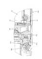
集塵容器141は、図3及び図4に示すように、粉塵フィルター149を収容する集塵容器本体145と、粉塵フィルター149を保持するフィルターホルダ147と、を主体として構成される。集塵容器本体145は、前後、上下、左右の各壁面のうち後側(図示右側)が開口された略方形の箱形に形成されている。フィルターホルダ147は、鉛直方向に延在する方形状の角枠部147aと当該角枠部147aの上端から前方に水平状に延在する天板部147bと、角枠部147aの下端から前方に水平状に延在する左右のアーム部147cとを有する枠状部材として形成されている。粉塵フィルター149は、外形が略直方体状に形成されるとともに1つの面が台座149aに固定されており、角枠部147aの開口を通して天板部147bとアーム部147cとの間に水平状に差し込まれた状態で周りをフィルターホルダ147で保持される。粉塵フィルター149を保持したフィルターホルダ147は、集塵容器本体145の開口側から内部に差し込まれるとともに、当該集塵容器本体145に取外し自在に取付けられる。また、フィルターホルダ147によって保持された粉塵フィルター149は、集塵容器141の各内壁面に対して所定の隙間を置いた状態で配置される。 As shown in FIGS. 3 and 4, the
また、集塵容器141は、集塵容器本体145の下面側後端部には略半円弧状の係合凹部145aが形成され、上面後部側には係止爪145b付きロックレバー145cが設けられている。そして図3において、集塵容器本体145を前傾姿勢とし、アタッチメント本体121における集塵モータ収容部121Bの前端下部に形成された円形受部121bに対し係合凹部145aを係合させた状態で当該円形受部121bを支点にして後方へ回動すれば、係止爪145bが粉塵移送部137側に形成された係止部137bに弾発状に係合する。かくして、図2に示すように、容器取付部121Aに対して安定的に取付けられる。一方、集塵容器141の取付状態において、ロックレバー145cを斜め下方へと押圧操作して係止部137bに対する係止爪145bの係合を解除後、円形受部121bを支点にして集塵容器本体145を前方へ回動することによって集塵容器141を容器取付部121Aから容易に取り外すことができる。すなわち、集塵容器141は、容器取付部121Aに対し取り外し自在に取付けられる構成とされる。 In addition, the
容器取付部121Aに集塵容器141が取付けられた状態において、ハンマビット119を被加工材に押し付け、ハンマドリル101を駆動して穴明け作業を遂行すると、当該加工作業で発生した粉塵は、被加工材に押し付けられた吸引筒部133の吸塵口133aから吸引された後、図2に矢印で示すように、吸引本体部135、粉塵移送部137を経て集塵容器141内に集められる。 In a state where the
さて、上記の粉塵の集塵時において、粉塵を吸い込んで集塵容器141に集める際に発生した静電気が当該集塵容器141に帯電し、作業者に対してあるいはモータ制御用のコントローラに対して悪影響を及ぼす可能性がある。このことに鑑み、本実施の形態においては、集塵容器141内に集められた粉塵と集塵モータ123の金属領域とを電気的に接続し、粉塵に帯電した静電気を集塵モータ123に逃がす構成としている。 Now, when collecting the dust, the static electricity generated when the dust is sucked and collected in the
このために、本実施の形態では、フィルターホルダ147が、樹脂にカーボンを練り込んだり表面に金属箔を蒸着したりする等の加工を施した導電性樹脂によって形成されるとともに、導電性ゴム(クロロプレンゴムにカーボンパウダーを添加したもの)によって形成された導電部材151を介して集塵モータ123の外郭を構成する金属製の外郭ハウジング124に電気的に接続される構成としている。フィルターホルダ147は、本発明における「アース部材」及び「導電材」に対応し、導電部材151は、本発明における「介在部材」に対応し、外郭ハウジング124は、本発明における「導電性領域」及び「外郭部材」に対応する。 For this reason, in this embodiment, the
導電部材151は、集塵モータ収容部121Bの前側下部に前後方向に延在状に配設されている。そして、集塵容器141の取付け取外しの回動支点となる円形受部121bの近傍において、延在方向の一端(前端側)がフィルターホルダ147の角枠部147aの下縁部と接触され、延在方向の他端が集塵モータ123の外郭ハウジング124に接触されている。これにより導電部材151は、フィルターホルダ147と集塵モータ123の外郭ハウジング124とを電気的に接続する。 The
また、導電部材151のうちフィルターホルダ147の角枠部147aの下縁部と対向する対向領域151aは、集塵容器141をアタッチメント本体121の容器取付部121Aに取付けるべく、集塵モータ収容部121Bの円形受部121bに集塵容器本体145の係合凹部145aを係合して後方へと回動させた際、フィルターホルダ147の角枠部147aの下縁部で上面を押圧されて弾性変形した状態で接触するように構成されている。 In addition, an opposing
上記のように構成された本実施の形態に係る集塵アタッチメント120によれば、集塵容器141内に集められた粉塵は、フィルターホルダ147及び導電部材151を通じて集塵モータ123の外郭ハウジング124と電気的に接続され、当該粉塵に帯電した静電気が外郭ハウジング124に逃げる。これにより集塵容器本体145の外表面に静電気の帯電を防止することができる。 According to the
特に本実施の形態では、フィルターホルダ147は、前述したように、集塵容器本体145内に延在する天板部147b及びアーム部147cを有する枠状部材として構成され、これにより集塵容器本体145内に集められる粉塵との接触可能な領域が十分に確保されている。このため、集塵容器本体145内に吸い込まれた粉塵に帯電した静電気を、フィルターホルダ147から導電部材151を通じて集塵モータ123の外郭ハウジング124に逃がし、作業者に対してあるいはモータ制御用のコントローラに対する静電気による悪影響を回避することができる。 In particular, in the present embodiment, the
また、導電部材151は、集塵容器141が容器取付部121Aに取付けられた状態では、フィルターホルダ147の角枠部147aの下縁部で押圧されて弾性変形され、これにより集塵容器141を容器取付部121Aに対して上下方向に関して弾発状に支持する構成である。このため、導電部材151とフィルターホルダ147との電気的接続を確保できるとともに、集塵容器141と容器取付部121Aとの間のがたつきを吸収し、かつ緩衝効果を得ることができる。すなわち、本実施の形態に係る導電部材151は、電気的接続と緩衝部材とを兼用する構成である。このため、各別に設置する場合に比べて部品点数が削減され、構造の簡素化に有効となる。 Further, the
なお、本実施の形態では、粉塵に帯電した静電気の逃がし先である導電性領域として、集塵モータ123の金属製の外郭ハウジング124を設定したが、これに限定されるものではない。例えば、ハンマドリル101の金属製部材としての、駆動モータの外郭ハウジング、あるいは本体部103を構成する本体ハウジング等を導電性領域として利用することが可能である。そして、ハンマドリル側の金属製部材を静電気の逃がし先として設定する場合にあっては、アース付きコネクタ(コンセントアース)を利用して静電気を逃がす構成とすることが可能である。 In the present embodiment, the metal
また、上述した実施の形態は、作業工具の一例としてハンマドリル101の場合で説明したが、ハンマビット119が長軸方向のハンマ動作のみを行なう電動ハンマに適用することも可能であるし、その他の切断工具、研削・研磨工具等に適用しても構わない。 Moreover, although embodiment mentioned above demonstrated in the case of the
101 ハンマドリル(作業工具)
103 本体部
109 ハンドグリップ
109A バッテリ装着部
109a トリガ
110 バッテリパック
117 ツールホルダ
119 ハンマビット(先端工具)
119a 先端部分
120 集塵アタッチメント(集塵装置)
121 アタッチメント本体(集塵容器本体)
121A 容器取付部(粉塵収容領域取付部)
121B 集塵モータ収容部
121b 円形受部
123 集塵モータ
124 外郭ハウジング(導電性領域)
125 集塵ファン
127 コネクタ
127A 本体側コネクタ
127B アタッチメント側コネクタ
131 粉塵吸引部(吸塵領域)
133 吸引筒部
133a 吸塵口
133b 後端壁部
135 吸引本体部
137 粉塵移送部(粉塵移送領域)
137A 可動筒部
137B 固定筒部
137b 係止部
139 ホース
141 集塵容器(粉塵収容領域)
142 開口
143 空気排出口
145 集塵容器本体
145a 係合凹部
145b 係止爪
145c ロックレバー
147 フィルターホルダ(アース部材、導電材)
147a 角枠部
147b 天板部
147c アーム部
149 粉塵フィルター
149a 台座
151 導電部材(介在部材)
151a 対向領域
101 Hammer drill (work tool)
103
121 Attachment body (dust container body)
121A Container mounting part (dust storage area mounting part)
121B Dust collection
125
133
137A
142
147a
151a opposite area
Claims (11)
Translated fromJapanese前記先端工具に対応して、加工作業時の粉塵を吸引する吸塵領域と、
前記吸塵領域で吸塵された粉塵を移送する粉塵移送領域と、
前記粉塵移送領域に連通されて粉塵を収容する粉塵収容領域と、
を有し、
さらに前記粉塵に帯電した静電気を逃がすアース部材を有し、
前記吸塵領域、前記粉塵移送領域および前記粉塵収容領域は、前記作業工具に対して一体状に着脱可能に構成されていることを特徴とする集塵装置。A dust collection unit that is detachably attached to the work tool and is carried along with the work tool, and collects dust generated when a predetermined machining operation is performed on a workpiece by driving a tip tool attached to the work tool. A dust device,
Corresponding to the tip tool, a dust-absorbing area for sucking dust during processing,
A dust transfer area for transferring dust absorbed in the dust absorption area;
A dust storage area that communicates with the dust transfer area and stores dust; and
Have
Furthermore, ithas a grounding member that releases static electricity charged in the dust,
The dust collection device, wherein the dust collectionregion, the dust transfer region, and the dust storage region are configured to be detachable integrally with the work tool .
前記アース部材は、前記粉塵収容領域に収容された粉塵に帯電した静電気を逃がすことを特徴とする集塵装置。It is a dust collector of Claim 1, Comprising:
The dust collecting apparatus, wherein the ground member releases static electricity charged in the dust accommodated in the dust accommodating area.
前記アース部材は、前記粉塵収容領域に臨むように配置された導電材によって構成されており、当該導電材を通じて粉塵に帯電した静電気を逃がすことを特徴とする集塵装置。It is a dust collector of Claim 2, Comprising:
The grounding member is made of a conductive material disposed so as to face the dust storage area, and discharges static electricity charged in the dust through the conductive material.
前記導電材は、前記集塵装置の導電性領域または当該集塵装置が取付けられた前記作業工具の導電性領域に電気的に接続され、前記粉塵収容領域に収容された粉塵に帯電した静電気を前記導電性領域に逃がすことを特徴とする集塵装置。It is a dust collector of Claim 3, Comprising:
The conductive material is electrically connected to the conductive region of the dust collector or the conductive region of the work tool to which the dust collector is attached, and is charged with static electricity charged to the dust stored in the dust storage region. A dust collector that escapes to the conductive region.
前記粉塵収容領域を取付けるための粉塵収容領域取付部を有し、
前記粉塵収容領域は、前記粉塵収容領域取付部に取外し自在に取付けられ、
前記粉塵収容領域取付部には、前記導電性領域と前記導電材とを接続する介在部材が設けられ、
前記介在部材は、前記粉塵収容領域が前記粉塵収容領域取付部に取付けられた状態において、前記導電性領域と前記導電材との電気的な接続と、前記粉塵収容領域と前記粉塵収容領域取付部の相互接触部の緩衝と、を兼務することを特徴とする集塵装置。It is a dust collector of Claim 4, Comprising:
A dust storage area mounting portion for mounting the dust storage area;
The dust storage area is detachably attached to the dust storage area mounting portion,
The dust storage region mounting portion is provided with an interposition member that connects the conductive region and the conductive material,
The interposition member includes an electrical connection between the conductive region and the conductive material, and the dust storage region and the dust storage region attachment portion in a state where the dust storage region is attached to the dust storage region attachment portion. A dust collector characterized by also serving as a buffer for the mutual contact portion of each other.
前記粉塵収容領域は、前記粉塵収容領域取付部に対して所定の支点周りに回動して着脱されるように構成されていることを特徴とする集塵装置。 The dust collecting device is configured to be attached to and detached from the dust containing region mounting portion by rotating around a predetermined fulcrum.
前記介在部材は、前記支点近傍に配置され、前記粉塵収容領域を前記支点周りに回動させて前記粉塵収容領域取付部に取り付ける動作に伴って、前記粉塵収容領域に弾発状に当接するように構成されていることを特徴とする集塵装置。 The interposition member is disposed in the vicinity of the fulcrum, and elastically abuts on the dust storage area as the dust storage area is rotated around the fulcrum and attached to the dust storage area mounting portion. It is comprised in the dust collector characterized by the above-mentioned.
前記粉塵収容領域は、粉塵フィルターが収容される集塵容器本体と、前記粉塵フィルターを保持するフィルターホルダとを有し、前記フィルターホルダが前記導電材によって形成されていることを特徴とする集塵装置。It is a dust collector in any one of Claims3-7 ,
The dust storage area has a dust collection container body in which a dust filter is stored and a filter holder for holding the dust filter, and the filter holder is formed of the conductive material. apparatus.
加工作業時に発生する粉塵を吸引して前記粉塵収容領域に収容するための吸引力を発生する集塵ファンと、当該集塵ファンを駆動する集塵モータと、をさらに有することを特徴とする集塵装置。It is a dust collector in any one of Claims1-8 ,
The dust collection fan further comprising: a dust collection fan that generates a suction force for sucking the dust generated during processing and storing the dust in the dust storage area; and a dust collection motor that drives the dust collection fan. Dust equipment.
前記集塵モータの外郭を構成する外郭部材が静電気を逃がす静電気収集領域として定められていることを特徴とする集塵装置。The dust collector according to claim9 , wherein
The dust collecting apparatus, wherein an outer member constituting an outer shell of the dust collecting motor is defined as a static electricity collecting region for releasing static electricity.
Power tool dust collecting device is mounted according to any one of claims1 to 10.
Priority Applications (6)
| Application Number | Priority Date | Filing Date | Title |
|---|---|---|---|
| JP2011171930AJP5729873B2 (en) | 2011-08-05 | 2011-08-05 | Dust collector |
| US13/554,474US8906124B2 (en) | 2011-08-05 | 2012-07-20 | Dust collecting device |
| RU2012131740/02ARU2012131740A (en) | 2011-08-05 | 2012-07-24 | DUST REMOVER |
| EP12177846.8AEP2554328B1 (en) | 2011-08-05 | 2012-07-25 | Dust collecting device with static charge dissipation |
| BRBR102012018934-8ABR102012018934A2 (en) | 2011-08-05 | 2012-07-30 | dust collector device |
| CN201210274684.5ACN102909697B (en) | 2011-08-05 | 2012-08-03 | Dust collecting device |
Applications Claiming Priority (1)
| Application Number | Priority Date | Filing Date | Title |
|---|---|---|---|
| JP2011171930AJP5729873B2 (en) | 2011-08-05 | 2011-08-05 | Dust collector |
Publications (2)
| Publication Number | Publication Date |
|---|---|
| JP2013035092A JP2013035092A (en) | 2013-02-21 |
| JP5729873B2true JP5729873B2 (en) | 2015-06-03 |
Family
ID=46582614
Family Applications (1)
| Application Number | Title | Priority Date | Filing Date |
|---|---|---|---|
| JP2011171930AActiveJP5729873B2 (en) | 2011-08-05 | 2011-08-05 | Dust collector |
Country Status (6)
| Country | Link |
|---|---|
| US (1) | US8906124B2 (en) |
| EP (1) | EP2554328B1 (en) |
| JP (1) | JP5729873B2 (en) |
| CN (1) | CN102909697B (en) |
| BR (1) | BR102012018934A2 (en) |
| RU (1) | RU2012131740A (en) |
Families Citing this family (37)
| Publication number | Priority date | Publication date | Assignee | Title |
|---|---|---|---|---|
| US9776296B2 (en) | 2008-05-09 | 2017-10-03 | Milwaukee Electric Tool Corporation | Power tool dust collector |
| JP5448951B2 (en)* | 2010-03-16 | 2014-03-19 | 株式会社マキタ | Power supply system for power tools with attachments |
| JP5657436B2 (en)* | 2011-03-16 | 2015-01-21 | 株式会社マキタ | Work tools |
| EP2754524B1 (en) | 2013-01-15 | 2015-11-25 | Corning Laser Technologies GmbH | Method of and apparatus for laser based processing of flat substrates being wafer or glass element using a laser beam line |
| EP2781296B1 (en) | 2013-03-21 | 2020-10-21 | Corning Laser Technologies GmbH | Device and method for cutting out contours from flat substrates using a laser |
| EP2803310A1 (en) | 2013-05-17 | 2014-11-19 | HILTI Aktiengesellschaft | Dust extraction device for a manual machine tool |
| US10293436B2 (en) | 2013-12-17 | 2019-05-21 | Corning Incorporated | Method for rapid laser drilling of holes in glass and products made therefrom |
| US11556039B2 (en) | 2013-12-17 | 2023-01-17 | Corning Incorporated | Electrochromic coated glass articles and methods for laser processing the same |
| USD742081S1 (en) | 2014-01-15 | 2015-10-27 | Milwaukee Electric Tool Corporation | Dust collector |
| USD741557S1 (en) | 2014-01-15 | 2015-10-20 | Milwaukee Electric Tool Corporation | Dust collector |
| CN106687419A (en) | 2014-07-08 | 2017-05-17 | 康宁股份有限公司 | Methods and apparatuses for laser processing materials |
| KR20170028943A (en) | 2014-07-14 | 2017-03-14 | 코닝 인코포레이티드 | System for and method of processing transparent materials using laser beam focal lines adjustable in length and diameter |
| US10047001B2 (en) | 2014-12-04 | 2018-08-14 | Corning Incorporated | Glass cutting systems and methods using non-diffracting laser beams |
| HUE055461T2 (en) | 2015-03-24 | 2021-11-29 | Corning Inc | Laser cutting and processing of display glass compositions |
| JP7082042B2 (en) | 2015-07-10 | 2022-06-07 | コーニング インコーポレイテッド | A method for continuously forming holes in a flexible substrate sheet and related products. |
| GB201515084D0 (en)* | 2015-08-25 | 2015-10-07 | Black & Decker Inc | Dust extractor |
| DE102015219224A1 (en)* | 2015-10-06 | 2017-04-06 | Robert Bosch Gmbh | suction |
| DE102015226021A1 (en)* | 2015-12-18 | 2017-06-22 | Robert Bosch Gmbh | suction |
| CN118906009A (en)* | 2016-01-20 | 2024-11-08 | 株式会社牧田 | Dust collecting device for electric tool, and dust collecting system |
| CN107053098A (en) | 2016-01-20 | 2017-08-18 | 株式会社牧田 | Dust collection device for electric tools, electric tools, and dust collection system |
| US11020846B2 (en)* | 2016-02-26 | 2021-06-01 | Koki Holdings Co., Ltd. | Work tool |
| JP6714443B2 (en)* | 2016-06-13 | 2020-06-24 | 株式会社マキタ | Dust collector and work tool |
| US10799996B2 (en)* | 2016-06-13 | 2020-10-13 | Makita Corporation | Dust collector and power tool |
| US10493577B2 (en)* | 2016-07-21 | 2019-12-03 | Makita Corporation | Dust collection device for electric power tool, electric power tool, and dust collection system |
| US10730783B2 (en) | 2016-09-30 | 2020-08-04 | Corning Incorporated | Apparatuses and methods for laser processing transparent workpieces using non-axisymmetric beam spots |
| EP3529214B1 (en) | 2016-10-24 | 2020-12-23 | Corning Incorporated | Substrate processing station for laser-based machining of sheet-like glass substrates |
| US10512997B2 (en)* | 2017-01-16 | 2019-12-24 | Makita Corporation | Dust collector for electric power tool and electric power tool |
| JP7007901B2 (en)* | 2017-12-26 | 2022-01-25 | 株式会社マキタ | Dust collector and work tools |
| CN109586523B (en)* | 2018-12-20 | 2020-09-08 | 浙江贝良风能电子科技有限公司 | Carbon powder receiving device for large and medium-sized wound motor |
| JP7183097B2 (en)* | 2019-03-26 | 2022-12-05 | 株式会社マキタ | Power tool dust collection system |
| JP2020157417A (en)* | 2019-03-26 | 2020-10-01 | 株式会社マキタ | Power tool, dust collection system of power tool |
| US11419466B2 (en) | 2020-03-25 | 2022-08-23 | Milwaukee Electric Tool Corporation | Dust collector assembly |
| CN112720369B (en)* | 2020-12-24 | 2022-07-08 | 嘉兴市名人电器股份有限公司 | Electric hammer dust collection device capable of being conveniently detached |
| JP1735375S (en)* | 2022-10-24 | 2023-01-25 | Dust collection attachment for portable electric hammer drills | |
| US20240416482A1 (en)* | 2023-06-15 | 2024-12-19 | X'pole Precision Tools Inc. | Electric tool grinding machine with static electricity dissipation |
| DE102024123242A1 (en)* | 2023-08-15 | 2025-02-20 | Milwaukee Electric Tool Corporation | Electrostatic discharge system for a power tool |
| CN120173631B (en)* | 2025-05-22 | 2025-08-12 | 山西立恒焦化有限公司 | Coke oven smoke collection device |
Family Cites Families (18)
| Publication number | Priority date | Publication date | Assignee | Title |
|---|---|---|---|---|
| IT1237154B (en)* | 1989-12-22 | 1993-05-24 | Black & Decker Italia | HANDLE WITH SUCTION HEAD FOR PORTABLE DRILL |
| DE4218247C2 (en)* | 1991-06-08 | 1995-05-18 | Wissner Rolf | Device for material-removing processing of a workpiece having a flat surface |
| DE19827173A1 (en)* | 1998-06-18 | 1999-12-23 | Bosch Gmbh Robert | Dust suction system for hand power tool |
| ATE329732T1 (en)* | 2000-01-27 | 2006-07-15 | S P Air Kk | PNEUMATIC ROTATION TOOL |
| DE10112129A1 (en)* | 2001-03-14 | 2002-09-19 | Hilti Ag | Intake module |
| DE10115116A1 (en)* | 2001-03-27 | 2002-10-10 | Hilti Ag | Dust extraction for a hand tool |
| GB0306487D0 (en) | 2003-03-21 | 2003-04-23 | Black & Decker Inc | Hand held drilling and/or hammering tool with dust collection unit |
| DE102004029220B4 (en)* | 2004-06-16 | 2006-03-23 | Hilti Ag | Hand tool with dust extraction module |
| JP4606109B2 (en)* | 2004-10-04 | 2011-01-05 | 株式会社マキタ | Drilling tool |
| DE602004011624T2 (en) | 2004-11-19 | 2009-01-29 | Black & Decker Inc., Newark | Dust extraction for powered tools |
| DE102005062887A1 (en)* | 2005-12-29 | 2007-07-05 | Robert Bosch Gmbh | Hand-held machine tool e.g. boring machine, for driving e.g. boring tool, has transmission unit designed as single unit with tool retaining unit, and channel formed as single piece with turbine unit supply channel |
| JP2007237328A (en)* | 2006-03-08 | 2007-09-20 | Hitachi Koki Co Ltd | Combustion power tool |
| JP5309738B2 (en)* | 2008-07-07 | 2013-10-09 | パナソニック株式会社 | Electric vacuum cleaner |
| JP2011171930A (en) | 2010-02-17 | 2011-09-01 | Sharp Corp | Receiver, method for synchronizing receiver, synchronization program of receiver, and synchronization circuit of receiver |
| JP5615725B2 (en)* | 2010-03-16 | 2014-10-29 | 株式会社マキタ | Electric tool with attachment |
| JP2011240285A (en)* | 2010-05-19 | 2011-12-01 | Makita Corp | Hose with cord, and dust collector |
| CN106377294B (en)* | 2010-12-21 | 2020-02-18 | 史赛克公司 | Control module for powered surgical tool including active seal |
| EP2809470B1 (en)* | 2012-02-03 | 2020-01-15 | Milwaukee Electric Tool Corporation | Rotary hammer |
- 2011
- 2011-08-05JPJP2011171930Apatent/JP5729873B2/enactiveActive
- 2012
- 2012-07-20USUS13/554,474patent/US8906124B2/enactiveActive
- 2012-07-24RURU2012131740/02Apatent/RU2012131740A/ennot_activeApplication Discontinuation
- 2012-07-25EPEP12177846.8Apatent/EP2554328B1/enactiveActive
- 2012-07-30BRBRBR102012018934-8Apatent/BR102012018934A2/ennot_activeApplication Discontinuation
- 2012-08-03CNCN201210274684.5Apatent/CN102909697B/enactiveActive
Also Published As
| Publication number | Publication date |
|---|---|
| CN102909697A (en) | 2013-02-06 |
| EP2554328B1 (en) | 2015-03-18 |
| BR102012018934A2 (en) | 2013-08-06 |
| US8906124B2 (en) | 2014-12-09 |
| JP2013035092A (en) | 2013-02-21 |
| EP2554328A1 (en) | 2013-02-06 |
| US20130031879A1 (en) | 2013-02-07 |
| CN102909697B (en) | 2015-05-20 |
| RU2012131740A (en) | 2014-01-27 |
Similar Documents
| Publication | Publication Date | Title |
|---|---|---|
| JP5729873B2 (en) | Dust collector | |
| WO2015122539A1 (en) | Dust collector and work tool provided with dust collector | |
| CN107486822B (en) | Dust collecting device and working tool | |
| CN110614612B (en) | Dust collecting system for electric tool | |
| JP6258063B2 (en) | Dust collector | |
| JP7664098B2 (en) | Dust collection system for power tools | |
| JP6211433B2 (en) | Dust collector | |
| JP7098432B2 (en) | Dust collection system for dust collection bit and hammer drill | |
| CN111745595B (en) | Dust collecting system | |
| JP6991743B2 (en) | Electric tool | |
| JP7309829B2 (en) | Electric tool | |
| JP6686341B2 (en) | Rechargeable tool | |
| JP6673755B2 (en) | Dust collectors and work tools | |
| JP2017119318A (en) | Work tools | |
| JP7158908B2 (en) | Dust collection system for power tools | |
| JP6714443B2 (en) | Dust collector and work tool | |
| JP7606411B2 (en) | Power tool system, power tool and dust collection device | |
| JP6720528B2 (en) | Work tools | |
| CN110625575B (en) | System comprising a handheld machine tool, a first and a second accessory, and a handheld machine tool or an accessory | |
| JP7532230B2 (en) | Dust collection attachments and power tools | |
| JP2019217589A (en) | Hammering bit and hammering tool | |
| JP2023125956A (en) | Electric tool system, electric tool, and dust collector | |
| JP2024178789A (en) | Dust collection system for power tools | |
| JP2024178790A (en) | Dust collection attachment for power tools and power tools | |
| JP2021053770A (en) | Power tool, power tool system, adaptor used for power tool and battery pack with adaptor |
Legal Events
| Date | Code | Title | Description |
|---|---|---|---|
| A621 | Written request for application examination | Free format text:JAPANESE INTERMEDIATE CODE: A621 Effective date:20140226 | |
| A131 | Notification of reasons for refusal | Free format text:JAPANESE INTERMEDIATE CODE: A131 Effective date:20141117 | |
| A977 | Report on retrieval | Free format text:JAPANESE INTERMEDIATE CODE: A971007 Effective date:20141120 | |
| A521 | Request for written amendment filed | Free format text:JAPANESE INTERMEDIATE CODE: A523 Effective date:20150115 | |
| TRDD | Decision of grant or rejection written | ||
| A01 | Written decision to grant a patent or to grant a registration (utility model) | Free format text:JAPANESE INTERMEDIATE CODE: A01 Effective date:20150401 | |
| A61 | First payment of annual fees (during grant procedure) | Free format text:JAPANESE INTERMEDIATE CODE: A61 Effective date:20150406 | |
| R150 | Certificate of patent or registration of utility model | Ref document number:5729873 Country of ref document:JP Free format text:JAPANESE INTERMEDIATE CODE: R150 | |
| R250 | Receipt of annual fees | Free format text:JAPANESE INTERMEDIATE CODE: R250 | |
| R250 | Receipt of annual fees | Free format text:JAPANESE INTERMEDIATE CODE: R250 | |
| R250 | Receipt of annual fees | Free format text:JAPANESE INTERMEDIATE CODE: R250 | |
| R250 | Receipt of annual fees | Free format text:JAPANESE INTERMEDIATE CODE: R250 | |
| R250 | Receipt of annual fees | Free format text:JAPANESE INTERMEDIATE CODE: R250 | |
| R250 | Receipt of annual fees | Free format text:JAPANESE INTERMEDIATE CODE: R250 | |
| R250 | Receipt of annual fees | Free format text:JAPANESE INTERMEDIATE CODE: R250 | |
| R250 | Receipt of annual fees | Free format text:JAPANESE INTERMEDIATE CODE: R250 |