JP5729176B2 - Movement guidance system, movement guidance apparatus, movement guidance method, and computer program - Google Patents
Movement guidance system, movement guidance apparatus, movement guidance method, and computer programDownload PDFInfo
- Publication number
- JP5729176B2 JP5729176B2JP2011147245AJP2011147245AJP5729176B2JP 5729176 B2JP5729176 B2JP 5729176B2JP 2011147245 AJP2011147245 AJP 2011147245AJP 2011147245 AJP2011147245 AJP 2011147245AJP 5729176 B2JP5729176 B2JP 5729176B2
- Authority
- JP
- Japan
- Prior art keywords
- guidance
- vehicle
- point
- branch point
- feature
- Prior art date
- Legal status (The legal status is an assumption and is not a legal conclusion. Google has not performed a legal analysis and makes no representation as to the accuracy of the status listed.)
- Active
Links
- 238000000034methodMethods0.000titleclaimsdescription32
- 238000004590computer programMethods0.000titleclaimsdescription8
- 238000001514detection methodMethods0.000claimsdescription20
- 238000003384imaging methodMethods0.000claimsdescription5
- 238000004364calculation methodMethods0.000description8
- 238000010586diagramMethods0.000description7
- 238000009434installationMethods0.000description7
- 238000013459approachMethods0.000description6
- 230000000694effectsEffects0.000description6
- 239000004973liquid crystal related substanceSubstances0.000description6
- 238000012545processingMethods0.000description5
- 238000004891communicationMethods0.000description4
- 230000006870functionEffects0.000description4
- 238000005259measurementMethods0.000description4
- 238000000926separation methodMethods0.000description4
- 238000005516engineering processMethods0.000description3
- 230000001413cellular effectEffects0.000description2
- 230000015654memoryEffects0.000description2
- 230000003287optical effectEffects0.000description2
- 239000003973paintSubstances0.000description2
- 206010039203Road traffic accidentDiseases0.000description1
- 238000012986modificationMethods0.000description1
- 230000004048modificationEffects0.000description1
- 238000003825pressingMethods0.000description1
- 230000001105regulatory effectEffects0.000description1
- 230000003936working memoryEffects0.000description1
Images


Classifications
- G—PHYSICS
- G01—MEASURING; TESTING
- G01C—MEASURING DISTANCES, LEVELS OR BEARINGS; SURVEYING; NAVIGATION; GYROSCOPIC INSTRUMENTS; PHOTOGRAMMETRY OR VIDEOGRAMMETRY
- G01C21/00—Navigation; Navigational instruments not provided for in groups G01C1/00 - G01C19/00
- G01C21/26—Navigation; Navigational instruments not provided for in groups G01C1/00 - G01C19/00 specially adapted for navigation in a road network
- G01C21/34—Route searching; Route guidance
- G01C21/36—Input/output arrangements for on-board computers
- G01C21/3626—Details of the output of route guidance instructions
- G01C21/3655—Timing of guidance instructions
- G—PHYSICS
- G01—MEASURING; TESTING
- G01C—MEASURING DISTANCES, LEVELS OR BEARINGS; SURVEYING; NAVIGATION; GYROSCOPIC INSTRUMENTS; PHOTOGRAMMETRY OR VIDEOGRAMMETRY
- G01C21/00—Navigation; Navigational instruments not provided for in groups G01C1/00 - G01C19/00
- G01C21/26—Navigation; Navigational instruments not provided for in groups G01C1/00 - G01C19/00 specially adapted for navigation in a road network
- G01C21/34—Route searching; Route guidance
- G01C21/36—Input/output arrangements for on-board computers
- G01C21/3626—Details of the output of route guidance instructions
- G01C21/3644—Landmark guidance, e.g. using POIs or conspicuous other objects
Landscapes
- Engineering & Computer Science (AREA)
- Radar, Positioning & Navigation (AREA)
- Remote Sensing (AREA)
- Automation & Control Theory (AREA)
- Physics & Mathematics (AREA)
- General Physics & Mathematics (AREA)
- Navigation (AREA)
- Instructional Devices (AREA)
Description
Translated fromJapanese本発明は、案内経路に基づいて移動体の移動を案内する移動案内システム、移動案内装置、移動案内方法及びコンピュータプログラムに関する。 The present invention relates to a movement guidance system, a movement guidance device, a movement guidance method, and a computer program that guide the movement of a moving body based on a guidance route.
近年、車両の走行案内を行い、運転者が所望の目的地に容易に到着できるようにしたナビゲーション装置が車両に搭載されていることが多い。ここで、ナビゲーション装置とは、GPS受信機などにより自車の現在位置を検出し、その現在位置に対応する地図データをDVD−ROMやHDDなどの記録媒体またはネットワークを通じて取得して液晶モニタに表示することが可能な装置である。更に、かかるナビゲーション装置には、所望する目的地を入力すると、出発地から目的地までの最適経路を探索する経路探索機能を備えている。そして、探索結果に基づいて設定された案内経路をディスプレイ画面に表示するとともに、右左折等の案内の対象となる分岐点(以下、案内分岐点という)に接近した場合には音声やディスプレイ画面を用いた案内を行うことによって、ユーザを所望の目的地まで確実に案内するようになっている。また、近年は携帯電話機、PDA(Personal Digital Assistant)、パーソナルコンピュータ等においても上記ナビゲーション装置と同様の機能を有するものがある。更に、車両以外にも歩行者や二輪車を対象として上記案内を行うことも可能である。 2. Description of the Related Art In recent years, a navigation device is often mounted on a vehicle that provides vehicle travel guidance so that a driver can easily arrive at a desired destination. Here, the navigation device detects the current position of the vehicle by a GPS receiver or the like, acquires map data corresponding to the current position through a recording medium such as a DVD-ROM or HDD or a network, and displays it on a liquid crystal monitor. It is a device that can do. Further, such a navigation device has a route search function for searching for an optimum route from the departure place to the destination when a desired destination is input. The guidance route set based on the search result is displayed on the display screen, and when approaching a branch point (hereinafter referred to as a guidance branch point) for guidance such as turning left or right, a voice or display screen is displayed. By performing the guidance used, the user is surely guided to a desired destination. In recent years, some cellular phones, PDAs (Personal Digital Assistants), personal computers, and the like have functions similar to those of the navigation device. Furthermore, it is also possible to perform the above guidance for pedestrians and two-wheeled vehicles as well as vehicles.
ここで、案内分岐点において右左折等の案内を行う場合には、案内分岐点をユーザに正確に特定させる必要がある。そして、このような案内分岐点をユーザに正確に特定させる案内方法の一つとして、案内分岐点の手前側にある分岐点である手前側分岐点に設置された信号機に基づく案内(例えば、車両の現在位置から案内分岐点までにある信号機の数を用いた案内)がある。 Here, when performing guidance such as turning left or right at the guidance branch point, it is necessary for the user to accurately identify the guidance branch point. And as one of the guidance methods which make a user specify such a guidance branch point correctly, guidance (for example, vehicle) based on the traffic light installed in the near branch point which is a branch point in the near side of a guide branch point Guidance using the number of traffic lights from the current position to the guidance junction.
例えば特開平10−274544号公報には、車両の現在位置から案内分岐点までにある信号機の数を用いた音声案内で案内分岐点の案内を行う場合において、案内分岐点から所定距離手前の地点や、案内分岐点までの所要時間が所定時間となる地点を案内出力地点として検出し、車両の現在位置が案内出力地点に到達した時点で案内を出力する技術について記載されている。 For example, in Japanese Patent Laid-Open No. 10-274544, when guidance of a guidance branch point is performed by voice guidance using the number of traffic lights from the current position of the vehicle to the guidance branch point, a point a predetermined distance before the guidance branch point. In addition, a technique is described in which a point where the required time to the guidance branch point is a predetermined time is detected as a guidance output point, and guidance is output when the current position of the vehicle reaches the guidance output point.
ここで、案内分岐点を特定させる案内を行う場合には、案内を適切なタイミングで開始することが重要である。特に、上記特許文献1のように手前側分岐点に設置された信号機に基づく案内では、他の案内(例えば移動体から案内分岐点までの距離を用いた案内等)に比べて、案内の内容に従って案内を適切なタイミングで開始することが重要である。そして、案内を適切なタイミングで開始しないと、ユーザが案内分岐点を誤って認識する虞が高くなる。 Here, when performing guidance for specifying a guidance branch point, it is important to start guidance at an appropriate timing. In particular, in the guidance based on the traffic light installed at the front branch point as in the above-mentioned
しかしながら、上記特許文献1のように案内分岐点から所定距離手前の地点や、案内分岐点までの所要時間が所定時間となる地点を案内の開始地点とすると、適切なタイミングで案内を開始することが難しく、ユーザが案内分岐点を誤って認識する虞があった。 However, if the point at which the required time from the guidance branch point to the guidance branch point and the required time to the guidance branch point is a predetermined time is set as the guidance start point as in
本発明は前記従来における問題点を解消するためになされたものであり、手前側分岐点に設置された信号機に基づく案内を、案内の内容に基づく適切なタイミングで開始することができ、ユーザに案内分岐点を正確に特定させることを可能にした移動案内システム、移動案内装置、移動案内方法及びコンピュータプログラムを提供することを目的とする。 The present invention has been made to solve the above-described conventional problems, and can guide a signal based on a traffic light installed at a front branch point at an appropriate timing based on the content of the guidance. It is an object of the present invention to provide a movement guidance system, a movement guidance device, a movement guidance method, and a computer program that can accurately specify a guidance branch point.
前記目的を達成するため本願の請求項1に係る移動案内システム(1)は、車両(71)の走行を案内する案内経路と該案内経路上の案内分岐点を設定する案内経路設定手段(13)と、前記案内分岐点よりも前記案内経路の出発地側に存在する手前分岐点(73〜75)の退出側信号機(77〜79)の位置を取得する信号機位置取得手段(13)と、前記車両の位置を取得する車両位置取得手段(13)と、前記車両に関する車両情報を取得する車両情報取得手段と、前記車両情報に基づいて、前記車両の乗員から前記手前分岐点の前記退出側信号機が視認できる状態から視認できなくなる状態へと切り替わる切替地点を特定する切替地点特定手段と、前記切替地点を前記案内分岐点の案内を開始する地点である案内開始地点として取得する案内開始地点取得手段(13)と、前記車両の位置と前記案内開始地点の位置とに基づいて、前記車両が前記案内開始地点を通過したか否か判定する通過判定手段(13)と、前記通過判定手段により前記車両が前記案内開始地点を通過したと判定された時に、前記案内分岐点の案内を開始する分岐点案内手段(13)と、を有することを特徴とする。
尚、「移動体」としては、車両以外に、歩行者や二輪車も含む。
また、「案内分岐点」とは、案内経路に従って移動体の移動の案内を行う際に、右左折指示等の案内を行う対象となる分岐点が該当する。
また、「退出側信号機」は、移動体の分岐点における通過方向において最も退出側に位置する信号機(即ち移動体が分岐点を通過する際に、その分岐点で最後に視認できる信号機)をいう。In order to achieve the above object, the travel guidance system (1) according to
The “moving body” includes a pedestrian and a two-wheeled vehicle in addition to the vehicle.
In addition, the “guidance branch point” corresponds to a branch point that is a target for performing guidance such as a right / left turn instruction when performing guidance of movement of the moving object according to the guidance route.
Further, the “exit-side traffic signal” refers to a traffic signal that is located on the most exit side in the passing direction at the branch point of the mobile body (that is, a traffic signal that can be visually recognized at the end when the mobile body passes through the branch point). .
また、請求項2に係る移動案内システム(1)は、請求項1に記載の移動案内システムであって、前記手前分岐点(73〜75)において前記案内経路の出発地側に存在する地物(81〜83)を検出する地物検出手段(13)と、前記地物検出手段により前記地物を検出した後の前記車両(71)の走行距離を算出する距離算出手段(13)と、前記地物から前記案内開始地点までの距離である地物距離を取得する地物距離取得手段(13)と、を有し、前記通過判定手段(13)は、前記走行距離と前記地物距離とに基づいて、前記車両が前記案内開始地点を通過したか否か判定することを特徴とする。
尚、「地物」としては、道路上又は道路付近において位置や角度が固定されている物が該当し、障害物、建造物、道路標識(路面標示含む)等がある。Moreover, the movement guidance system (1) according to
The “feature” includes an object whose position and angle are fixed on or near the road, and includes an obstacle, a building, a road sign (including a road sign), and the like.
また、請求項3に係る移動案内システム(1)は、請求項2に記載の移動案内システムであって、前記地物検出手段(13)は、前記車両(71)に設置された撮像手段(19)より撮像した画像に基づいて、前記車両が走行する道路に形成された前記地物(81〜83)を検出し、前記通過判定手段(13)は、前記地物検出手段により前記地物を検出した際の前記地物から前記車両までの距離に前記走行距離を加算した距離が前記地物距離以上となった場合に、前記車両が前記案内開始地点を通過したと判定することを特徴とする。Further, the movement guidance system (1) according to
また、請求項4に係る移動案内システム(1)は、請求項2又は請求項3に記載の移動案内システムであって、前記地物検出手段(13)によって検出された前記地物(81〜83)と該地物の位置情報とが対応付けられた地物情報を取得する地物情報取得手段(13)を有し、前記信号機距離取得手段(13)は、前記地物情報と前記手前分岐点(73〜75)の前記退出側信号機(77〜79)の位置情報とに基づいて前記信号機距離を取得することを特徴とする。 Further, the movement guidance system (1) according to claim 4 is the movement guidance system according to
また、請求項5に係る移動案内システム(1)は、請求項2乃至請求項4のいずれかに記載の移動案内システムであって、前記地物(81〜83)は、前記車両(71)が走行する路面に形成された路面標示であることを特徴とする。
尚、「路面標示」としては、停止線、横断歩道、文字列、最高速度等がある。Further, the movement guidance system (1) according to
“Road markings” include stop lines, pedestrian crossings, character strings, maximum speed, and the like.
また、請求項6に係る移動案内システム(1)は、請求項5に記載の移動案内システムであって、前記地物検出手段(13)は、前記路面標示として停止線を検出することを特徴とする。 Further, the movement guidance system (1) according to claim 6 is the movement guidance system according to
また、請求項7に係る移動案内装置(1)は、車両(71)の走行を案内する案内経路と該案内経路上の案内分岐点を設定する案内経路設定手段(13)と、前記案内分岐点よりも前記案内経路の出発地側に存在する手前分岐点(73〜75)の退出側信号機(77〜79)の位置を取得する信号機位置取得手段(13)と、前記車両の位置を取得する車両位置取得手段(13)と、前記車両に関する車両情報を取得する車両情報取得手段と、前記車両情報に基づいて、前記車両の乗員から前記手前分岐点の前記退出側信号機が視認できる状態から視認できなくなる状態へと切り替わる切替地点を特定する切替地点特定手段と、前記切替地点を前記案内分岐点の案内を開始する地点である案内開始地点として取得する案内開始地点取得手段(13)と、前記車両の位置と前記案内開始地点の位置とに基づいて、前記車両が前記案内開始地点を通過したか否か判定する通過判定手段(13)と、前記通過判定手段により前記車両が前記案内開始地点を通過したと判定された時に、前記案内分岐点の案内を開始する分岐点案内手段(13)と、を有することを特徴とする。The movement guide device (1) according to claim7 includes a guide route for guiding thetravel of thevehicle (71), a guide route setting means (13) for setting a guide branch point on the guide route, and the guide branch. Signal position acquisition means (13) for acquiring the position of the exit side traffic signal (77 to 79) at the near branch point (73 to 75) existing on the departure side of the guide route from the point, and the position of thevehicleVehicle position acquisition means (13),vehicle information acquisition means for acquiring vehicle information relating to the vehicle, and a state in which the exit-side traffic light at the front branch point is visible from the vehicle occupant based on the vehicle information. a switching point specifying means for specifying a switching point of switching to the viewing can not become a state, guidance starting point obtaining means for obtainingthe switching pointas a guidance start point is a point at which to start the guidance of the guide branch point ( And 3), on the basis of the position of thevehicle and the position of the guidance starting point, and thevehicle for determining whether passage determination means has passed through the guidance starting point (13), saidvehicle by said passing determining means Branch point guidance means (13) for starting guidance of the guidance branch point when it is determined that has passed the guidance start point.
また、請求項8に係る移動案内方法は、案内経路設定手段が、車両(71)の走行を案内する案内経路と該案内経路上の案内分岐点(72)を設定するステップと、信号機位置取得手段が、前記案内分岐点よりも前記案内経路の出発地側に存在する手前分岐点(73〜75)の退出側信号機(77〜79)の位置を取得するステップと、車両位置取得手段が、前記車両の位置を取得するステップと、車両情報取得手段が、前記車両に関する車両情報を取得するステップと、切替地点特定手段が、前記車両情報に基づいて、前記車両の乗員から前記手前分岐点の前記退出側信号機が視認できる状態から視認できなくなる状態へと切り替わる切替地点を特定するステップと、案内開始地点取得手段が、前記切替地点を前記案内分岐点の案内を開始する地点である案内開始地点として取得するステップと、通過判定手段が、前記車両の位置と前記案内開始地点の位置とに基づいて、前記車両が前記案内開始地点を通過したか否か判定するステップと、分岐点案内手段が、前記通過判定手段により前記車両が前記案内開始地点を通過したと判定された時に、前記案内分岐点の案内を開始するステップと、を有することを特徴とする。The mobile guide method according to claim8,the guide route setting means, andaway step set thevehicle guidance branch point on the guidance route and the guide path for guiding therunning of (71) (72),traffic position acquisition means includesLuz step to obtain the position of the guide than the branch points present in the starting point side of the guide path prior branch point (73-75) of the exit-side traffic (77-79), the vehicle position acquisition means includesLuz step to obtain the position of thevehicle,vehicle information acquisition unit, acquiring vehicle information concerning the vehicle, the switching point specification means, based on the vehicle information, passenger of the vehicle startingidentifying a switching point of switching to the exit-side traffic can not be visually recognized from the state visible state of the preceding junction, guidance start point obtaining means, the guidesaid switching point of the guidance branch pointfrom That theabsence steps be takenas a guidance start point is the point,passing judgment means, on the basis of the position of thevehicle and the position of the guidance starting point, determining whether thevehicle has passed the guidance starting point and beaway step,junction guiding means, when thevehicle is determined to have passed through the guidance starting point by the passing determiningmeans, having aLuz step to start guidance of the guide branch point It is characterized by.
更に、請求項9に係るコンピュータプログラムは、コンピュータを、車両(71)の走行を案内する案内経路と該案内経路上の案内分岐点(72)を設定する案内経路設定手段と、前記案内分岐点よりも前記案内経路の出発地側に存在する手前分岐点(73〜75)の退出側信号機(77〜79)の位置を取得する信号機位置取得手段と、前記車両の位置を取得する車両位置取得手段と、前記車両に関する車両情報を取得する車両情報取得手段と、前記車両情報に基づいて、前記車両の乗員から前記手前分岐点の前記退出側信号機が視認できる状態から視認できなくなる状態へと切り替わる切替地点を特定する切替地点特定手段と、前記切替地点を前記案内分岐点の案内を開始する地点である案内開始地点として取得する案内開始地点取得手段と、前記車両の位置と前記案内開始地点の位置とに基づいて、前記車両が前記案内開始地点を通過したか否か判定する通過判定手段と、前記通過判定手段により前記車両が前記案内開始地点を通過したと判定された時に、前記案内分岐点の案内を開始する分岐点案内手段と、して機能させることを特徴とする。Furthermore, the computer program according to claim9 is a computer program for causing the computer to guide thetravel of thevehicle (71), a guide route settingmeans for setting a guide branch point (72) on the guide route, and the guide branch point. a traffic light position acquisitionmeans for acquiring a position of prior branch points present in the starting point side (73-75) of the exit-side traffic (77-79) of the guide path than avehicle position acquisition for acquiring a position of thevehicleIt switchedmeans,the vehicle information acquisition unit that acquires vehicle information about the vehicle, based on the vehicle information, and from the occupant of the vehicle to the exit-side traffic can not be visually recognized from the state visible state of the preceding junction a switching point specifying means for specifying a switching point, guidance starting point acquisitionhand to acquirethe switching pointas a guidance start point is a point at which to start the guidance of the guide branch point If, on the basis of the position of thevehicle and the position of the guidance starting point, and determining passage determinationunit determining whether or not thevehicle has passed the guidance starting point, thevehicle is the guidance starting point by the passing determiningmeans When it is determined that the vehicle has passed, it ismade to function as a branch point guidemeans for starting guidance of the guide branch point.
前記構成を有する請求項1に記載の移動案内システムによれば、手前分岐点に設置された退出側信号機に対する相対位置によって特定される案内開始地点を車両が通過したタイミングで案内分岐点の案内を開始するので、案内の内容に基づく適切なタイミングで案内分岐点の案内を開始することが可能となる。従って、ユーザに案内分岐点を正確に特定させることが可能となる。
また、車両の乗員から手前分岐点の退出側信号機が視認できる状態から視認できなくなる状態へと切り替わる切替地点を案内開始地点とするので、手前分岐点の退出側信号機が視認できなくなった時点で案内分岐点の案内を開始することが可能となる。その結果、案内内容に基づく適切なタイミングで案内分岐点の案内を開始することが可能となる。特に信号機を用いた案内を行う場合には、その効果は顕著なものとなる。According to the movement guidance system according to
In addition, since the switching point where the exit signal at the front branching point from the vehicle occupant is visible to the state where it cannot be viewed is set as the guidance start point, guidance is provided when the exit signal at the front branching point becomes invisible. It becomes possible to start the guidance of the branch point. As a result, it is possible to start guidance at the guidance branch point at an appropriate timing based on the guidance content. In particular, when performing guidance using a traffic light, the effect becomes remarkable.
また、請求項2に記載の移動案内システムによれば、地物を検出した後の車両の走行距離と、地物から案内開始地点までの地物距離とに基づいて、車両が案内開始地点を通過したか否か判定するので、手前分岐点に設置された地物を用いて、車両と案内開始地点との位置関係を正確に特定することが可能となる。その結果、車両が案内開始地点を通過した正確なタイミングで案内分岐点の案内を開始することが可能となる。Further, according to the mobile guidance system according to
また、請求項3に記載の移動案内システムによれば、車両が撮像手段により地物を撮像することによって、地物を撮像した後の車両の位置を、該地物に対する相対位置により正確に特定することが可能となる。その結果、車両と案内開始地点との位置関係を正確に特定することが可能となり、車両が案内開始地点を通過した正確なタイミングで案内分岐点の案内を開始することが可能となる。Further, according to the mobile guidance system according to
また、請求項4に記載の移動案内システムによれば、地物と該地物の位置情報とが対応付けられた地物情報に基づいて、地物から案内開始地点までの地物距離を取得するので、別途に地物距離を算出する為の特別な処理を行うことなく、地物情報から地物距離を容易に算出することが可能となる。 According to the movement guidance system of claim 4, the feature distance from the feature to the guidance start point is acquired based on the feature information in which the feature and the position information of the feature are associated with each other. Therefore, it is possible to easily calculate the feature distance from the feature information without performing a special process for calculating the feature distance separately.
また、請求項5に記載の移動案内システムによれば、路面に形成された路面標示を検出した後の車両の走行距離と、路面標示から案内開始地点までの地物距離とに基づいて、車両が案内開始地点を通過したか否か判定するので、手前分岐点に設置された停止線や横断歩道等の路面標示を用いて、車両と案内開始地点との位置関係を正確に特定することが可能となる。Further, according to the mobile guidance system according to
また、請求項6に記載の移動案内システムによれば、路面に形成された停止線を検出した後の車両の走行距離と、停止線から案内開始地点までの地物距離とに基づいて、車両が案内開始地点を通過したか否か判定するので、手前分岐点に設置された停止線を用いて、車両と案内開始地点との位置関係を正確に特定することが可能となる。また、停止線は信号機の設置された分岐点周辺の路面に描かれている可能性が極めて高いので、車両が手前分岐点を通過する際に、車両と案内開始地点との位置関係を確実に特定することが可能となる。Moreover, according to the movement guidance system of Claim 6, based on thetravel distance of thevehicle after detecting the stop line formed on the road surface, and the feature distance from the stop line to the guidance start point, thevehicle Therefore, it is possible to accurately specify the positional relationship between thevehicle and the guidance start point using the stop line installed at the front branch point. In addition, the possibility that the stop line is drawn on the road surface around the branch point where the traffic signal is installed is very high, so when thevehicle passes the front branch point, the positional relationship between thevehicle and the guidance start point is ensured. It becomes possible to specify.
また、請求項7に記載の移動案内装置によれば、手前分岐点に設置された退出側信号機に対する相対位置によって特定される案内開始地点を車両が通過したタイミングで案内分岐点の案内を開始するので、案内の内容に基づく適切なタイミングで案内分岐点の案内を開始することが可能となる。従って、ユーザに案内分岐点を正確に特定させることが可能となる。
また、車両の乗員から手前分岐点の退出側信号機が視認できる状態から視認できなくなる状態へと切り替わる切替地点を案内開始地点とするので、手前分岐点の退出側信号機が視認できなくなった時点で案内分岐点の案内を開始することが可能となる。その結果、案内内容に基づく適切なタイミングで案内分岐点の案内を開始することが可能となる。特に信号機を用いた案内を行う場合には、その効果は顕著なものとなる。According to the movement guide device of theseventh aspect, the guidance of the guidance branch point is started at the timing when thevehicle passes the guidance start point specified by the relative position with respect to the exit side traffic signal installed at the front branch point. Therefore, it is possible to start guidance for the guidance branch point at an appropriate timing based on the content of the guidance. Therefore, it is possible to make the user specify the guidance branch point accurately.
Also, since the switching point where the exit signal at the front branch point is visible from the vehicle occupant to the state where it is no longer visible is set as the guidance start point, guidance is provided when the exit signal at the front branch point becomes invisible. It becomes possible to start the guidance of the branch point. As a result, it is possible to start guidance at the guidance branch point at an appropriate timing based on the guidance content. In particular, when performing guidance using a traffic light, the effect becomes remarkable.
また、請求項8に記載の移動案内方法によれば、手前分岐点に設置された退出側信号機に対する相対位置によって特定される案内開始地点を車両が通過したタイミングで案内分岐点の案内を開始するので、案内の内容に基づく適切なタイミングで案内分岐点の案内を開始することが可能となる。従って、ユーザに案内分岐点を正確に特定させることが可能となる。
また、車両の乗員から手前分岐点の退出側信号機が視認できる状態から視認できなくなる状態へと切り替わる切替地点を案内開始地点とするので、手前分岐点の退出側信号機が視認できなくなった時点で案内分岐点の案内を開始することが可能となる。その結果、案内内容に基づく適切なタイミングで案内分岐点の案内を開始することが可能となる。特に信号機を用いた案内を行う場合には、その効果は顕著なものとなる。According to the movement guidance method of theeighth aspect, guidance of the guidance branch point is started at the timing when thevehicle passes the guidance start point specified by the relative position with respect to the exit side traffic signal installed at the front branch point. Therefore, it is possible to start guidance for the guidance branch point at an appropriate timing based on the content of the guidance. Therefore, it is possible to make the user specify the guidance branch point accurately.
Also, since the switching point where the exit signal at the front branch point is visible from the vehicle occupant to the state where it is no longer visible is set as the guidance start point, guidance is provided when the exit signal at the front branch point becomes invisible. It becomes possible to start the guidance of the branch point. As a result, it is possible to start guidance at the guidance branch point at an appropriate timing based on the guidance content. In particular, when performing guidance using a traffic light, the effect becomes remarkable.
更に、請求項9に記載のコンピュータプログラムによれば、手前分岐点に設置された退出側信号機に対する相対位置によって特定される案内開始地点を車両が通過したタイミングで案内分岐点の案内を開始させるので、案内の内容に基づく適切なタイミングで案内分岐点の案内を開始させることが可能となる。従って、ユーザに案内分岐点を正確に特定させることが可能となる。
また、車両の乗員から手前分岐点の退出側信号機が視認できる状態から視認できなくなる状態へと切り替わる切替地点を案内開始地点とするので、手前分岐点の退出側信号機が視認できなくなった時点で案内分岐点の案内を開始することが可能となる。その結果、案内内容に基づく適切なタイミングで案内分岐点の案内を開始することが可能となる。特に信号機を用いた案内を行う場合には、その効果は顕著なものとなる。Further, according to the computer program of theninth aspect, since the guidance of the guidance branch point is started at the timing when thevehicle passes the guidance start point specified by the relative position with respect to the exit side traffic signal installed at the front branch point. It is possible to start guidance at the guidance branch point at an appropriate timing based on the content of the guidance. Therefore, it is possible to make the user specify the guidance branch point accurately.
Also, since the switching point where the exit signal at the front branch point is visible from the vehicle occupant to the state where it is no longer visible is set as the guidance start point, guidance is provided when the exit signal at the front branch point becomes invisible. It becomes possible to start the guidance of the branch point. As a result, it is possible to start guidance at the guidance branch point at an appropriate timing based on the guidance content. In particular, when performing guidance using a traffic light, the effect becomes remarkable.
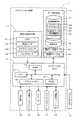
以下、本発明に係る移動案内システム及び移動案内装置をナビゲーション装置に具体化した一実施形態に基づき図面を参照しつつ詳細に説明する。先ず、本実施形態に係るナビゲーション装置1の概略構成について図1を用いて説明する。図1は本実施形態に係るナビゲーション装置1を示したブロック図である。 DETAILED DESCRIPTION OF THE PREFERRED EMBODIMENTS Hereinafter, a movement guide system and a movement guide apparatus according to the present invention will be described in detail with reference to the drawings based on an embodiment in which the navigation apparatus is embodied. First, a schematic configuration of the
図1に示すように本実施形態に係るナビゲーション装置1は、ナビゲーション装置1が搭載された車両の現在位置を検出する現在位置検出部11と、各種のデータが記録されたデータ記録部12と、入力された情報に基づいて、各種の演算処理を行うナビゲーションECU13と、ユーザからの操作を受け付ける操作部14と、ユーザに対して車両周辺の地図や施設の関する施設情報を表示する液晶ディスプレイ15と、経路案内に関する音声ガイダンスを出力するスピーカ16と、記憶媒体であるDVDを読み取るDVDドライブ17と、プローブセンタやVICS(登録商標:Vehicle Information and Communication System)センタ等の情報センタとの間で通信を行う通信モジュール18と、から構成されている。また、ナビゲーション装置1には後述する路面標示を検出する為のバックカメラ19が接続されている。 As shown in FIG. 1, the
以下に、ナビゲーション装置1を構成する各構成要素について順に説明する。
現在位置検出部11は、GPS21、車速センサ22、ステアリングセンサ23、ジャイロセンサ24等からなり、現在の車両の位置、方位、車両の走行速度、現在時刻等を検出することが可能となっている。ここで、特に車速センサ22は、車両の移動距離や車速を検出する為のセンサであり、車両の駆動輪の回転に応じてパルスを発生させ、パルス信号をナビゲーションECU13に出力する。そして、ナビゲーションECU13は発生するパルスを計数することにより駆動輪の回転速度や移動距離を算出する。尚、上記5種類のセンサをナビゲーション装置1が全て備える必要はなく、これらの内の1又は複数種類のセンサのみをナビゲーション装置1が備える構成としても良い。Below, each component which comprises the
The current
また、データ記録部12は、外部記憶装置及び記録媒体としてのハードディスク(図示せず)と、ハードディスクに記録された地図情報DB31、地物DB32、案内フレーズ条件テーブル33、地物テーブル34及び所定のプログラム等を読み出すとともにハードディスクに所定のデータを書き込む為のドライバである記録ヘッド(図示せず)とを備えている。尚、データ記録部12をハードディスクの代わりにメモリーカードやCDやDVD等の光ディスクにより構成しても良い。 The
ここで、地図情報DB31は、例えば、道路(リンク)に関するリンクデータ35、ノード点に関するノードデータ36、各分岐点に関する分岐点データ37、施設等の地点に関する地点データ、地図を表示するための地図表示データ、経路を探索するための探索データ、地点を検索するための検索データ等が記憶された記憶手段である。 Here, the
ここで、リンクデータ35としては、例えば、該リンクを識別するリンクID、該リンクの端部に位置するノードを特定する端部ノード情報、該リンクを構成する道路の道路種別、車線数等が記憶される。また、ノードデータ36としては、該ノードを識別するノードID、該ノードの位置座標、該ノードがリンクを介して接続される接続先ノードを特定する接続先ノード情報等が記憶される。また、分岐点データ37としては、該分岐点(交差点)を形成するノードを特定する該当ノード情報、該分岐点に接続されるリンク(以下、接続リンクという)を特定する接続リンク情報、分岐点の周辺に設置された信号機に関する信号機情報38等が記憶される。 Here, the
また、信号機情報38としては、全国の各分岐点(交差点)の周辺に設置された信号機について、信号機の設置された方向(即ち、信号機のライトが向いている方向であり、以下、設置方向という)や灯数(3灯式、1灯式等)や信号機の設置された位置座標(以下、設置座標という)等が記憶される。更に、一の分岐点に対して複数の信号機が設置されている場合には、複数の信号機毎に上記設置方向や設置座標等が記憶される。例えば、図2に示すように片側2車線の道路が交差する分岐点51では、8個の信号機52〜59が設置されている。従って、分岐点51の信号機情報38としては、信号機52〜59の設置方向や設置座標等が記憶される。 In addition, the
尚、信号機情報38としては、分岐点からの退出方向毎に、最も退出側にある信号機(即ち車両が分岐点を通過する際に最後に視認できる信号機であり、以下、退出側信号機という)に関する情報のみを記憶する構成としても良い。例えば、図2に示す分岐点51では、図の下から上への退出方向に対して退出側信号機である信号機53に関する情報を記憶し、図の上から下への退出方向に対して退出側信号機である信号機55に関する情報を記憶し、図の左から右への退出方向に対して退出側信号機である信号機57に関する情報を記憶し、図の右から左への退出方向に対して退出側信号機である信号機59に関する情報を記憶する。即ち、8個の信号機52〜59の内、信号機53、55、57、59の設置方向と設置座標のみを記憶する構成としても良い。また、分岐点からの進入方向毎に、最も進入側(即ち出発地側)にある信号機(即ち車両が最初に視認できる信号機であり、以下、進入側信号機という)に関する情報のみを記憶する構成としても良い。更に、信号機の代わりに停止線に関する情報を記憶する構成としても良い。
そして、ナビゲーションECU13は、後述のように地図情報DB31に記憶された各データに基づいて、車両の進行方向前方にある案内分岐点と該案内分岐点よりも案内経路の出発地側に存在する分岐点(以下、手前分岐点という)を特定する。また、案内分岐点や手前分岐点の周辺にある信号機の信号機情報38を取得する。そして、特定された案内分岐点や手前分岐点に関する情報や取得した信号機情報38に基づいて、後述の地物テーブル34(図8参照)を作成する。尚、案内分岐点とは、ナビゲーション装置1に設定されている案内経路に従ってナビゲーション装置1が走行の案内を行う際に、右左折指示等の案内を行う対象となる分岐点である。Note that the
And navigation ECU13 is based on each data memorize | stored in map information DB31 as mentioned later, and the branch existing in the departure place side of a guidance route from this guidance branch point ahead of the advancing direction of a vehicle. A point (hereinafter referred to as a front branch point) is specified. Moreover, the
また、地物DB32は、路面上に形成された地物である路面標示に関する情報が記憶されたDBである。ここで、図3は地物DB32の記憶領域の一例を示した図である。図3に示すように、地物DB32は、路面標示の位置を地図上で特定する座標データと、路面上に形成された路面標示の種類(例えば、停止線、横断歩道、文字列、最高速度)を識別する為の種類情報と、識別IDと、路面標示に関連付けられた制御対象物(停止線、コーナ、分岐点、信号機等)と、路面標示に関連付けられた制御対象物までの道なり距離から構成される。 The
例えば、図3に示す例では、座標(x1,y1)には「停止線(ID:123)」の路面標示が形成されており、且つその路面標示には8m前方に制御対象物として「分岐点」が対応付けられていることを示す。そして、ナビゲーションECU13はバックカメラ19で撮像した撮像画像から地物DB32に記録されたいずれかの路面標示を認識した場合に、認識した路面標示に関連付けられた制御対象物までの道なり距離に基づいて車両から制御対象物までの詳細な距離を間接的に算出する。そして、算出された距離に基づいて案内や車両制御を行う。 For example, in the example shown in FIG. 3, a road marking of “stop line (ID: 123)” is formed at the coordinates (x1, y1), and the road marking is “branched” as a
また、案内フレーズ条件テーブル33は、案内分岐点の案内について、発話されるフレーズの内容とともに、案内の発話を開始する条件等がそれぞれ対応付けられて記憶されたテーブルである。以下に、案内フレーズ条件テーブル33について具体例を挙げてより詳細に説明する。図4は案内フレーズ条件テーブル33の一例を示した図である。図5は、図4に示す案内フレーズ条件テーブル33で規定された案内開始地点を説明した図である。尚、図4では、案内分岐点で行われる案内の内、特に案内分岐点に信号機が設置されている場合であって、該信号機を用いた表現内容で右左折の案内を行う場合に出力される案内について示す。また、以下の実施例の説明では、案内分岐点及び手前分岐点はいずれも信号機の設置された分岐点であり、案内分岐点の一つ手前側(案内経路に沿った出発地側)の分岐点を第1手前分岐点と称し、第1手前分岐点の更に一つ手前側(案内経路に沿った出発地側)の分岐点を第2手前分岐点と称し、第2手前分岐点の更に一つ手前側(案内経路に沿った出発地側)の分岐点を第3手前分岐点と称して説明する。 In addition, the guidance phrase condition table 33 is a table in which the guidance utterance guidance and the conditions for starting the guidance utterance are stored in association with the contents of the spoken phrase. Hereinafter, the guidance phrase condition table 33 will be described in more detail with specific examples. FIG. 4 is a view showing an example of the guidance phrase condition table 33. FIG. 5 is a diagram for explaining a guidance start point defined in the guidance phrase condition table 33 shown in FIG. In addition, in FIG. 4, it is the case where the traffic signal is installed at the guidance branch point among the guidance performed at the guidance branch point, and is output when the right and left turn guidance is performed with the expression content using the traffic signal. I will show you the guidance. In the following description of the embodiment, the guide branch point and the front branch point are both branch points where a traffic light is installed, and the branch on the one side before the guide branch point (the departure side along the guide route). The point is referred to as the first front branch point, the branch point on the further one side of the first front branch point (the departure side along the guide route) is referred to as the second front branch point, and further to the second front branch point. A branch point on the front side (the departure side along the guide route) will be referred to as a third front branch point.
図4に示すように、例えば、「2つ目の信号を左(右)方向です」との案内を行う場合には、案内分岐点に進入するまでに案内分岐点を含めて2箇所の信号機をユーザがカウントできる状態にある間に、案内の発話を開始する必要がある。従って、「2つ目の信号を左(右)方向です」との案内フレーズは、第2手前分岐点の退出側信号機に対して設定された案内開始地点を車両が通過したことを条件として案内を開始する。また、本実施形態において、第2手前分岐点の退出側信号機に設定された案内開始地点は、車両の乗員(特に運転手)から第2手前分岐点の退出側信号機が視認できる状態から視認できなくなる状態へと切り替わる地点が相当する。ここで、車両の乗員から第2手前分岐点の退出側信号機が視認できる状態から視認できなくなる状態へと切り替わる地点は、退出側信号機に対する相対的な位置関係によって特定されるが、その地点は車種毎に(より具体的には車の形状やフロントウィンドウの形状によって)異なる。例えば、第2手前分岐点の退出側信号機の5m手前の地点を車両が通過する時点で、車両の乗員から第2手前分岐点の退出側信号機が視認できる状態から視認できなくなる状態へと切り替わる場合には、図5に示すように、案内分岐点61に対して2つ手前側の第2手前分岐点62の退出側信号機63の5m手前の地点Aを案内開始地点とし、地点Aを車両が通過した時点で、案内分岐点の案内が開始される。その結果、案内を受けたユーザは、案内分岐点61に進入するまでに第1手前分岐点64と案内分岐点61の2箇所の信号機の設置された分岐点をカウントすることが可能となり、案内文中の『2つ目の信号』が案内分岐点61に設置された進入側信号機65であることを明確に特定することが可能となる。
尚、案内フレーズ中の信号機の数は、分岐点単位での信号機の数とすることが望ましい。即ち、大型の道路等において同一分岐点に複数の信号機が設けられている場合には、該複数の信号機は1の信号機としてカウントすることが望ましい。その場合には、案内フレーズ中の信号機の数は、信号機の設置された分岐点(即ち、信号機交差点)の数に相当する。但し、分岐点単位でカウントする場合であっても、分岐点以外に設置された信号機(例えば押しボタン式信号機等)も信号機の数としてカウントすることが望ましい。以下の説明でも同様である。
案内フレーズ条件テーブル33には、同様にして他の案内フレーズについても記憶されている。尚、案内分岐点の案内方向は、左(右)方向以外に、右(左)斜め方向や右(左)手前方向等も存在する。As shown in FIG. 4, for example, in the case of guiding “the second signal is in the left (right) direction”, two traffic lights including the guidance branch point before entering the guidance branch point. Utterance of guidance must be started while the user is ready to count. Therefore, the guidance phrase “the second signal is in the left (right) direction” is guided on the condition that the vehicle has passed the guidance start point set for the exit side traffic light at the second front branch point. To start. In the present embodiment, the guidance start point set for the exit signal at the second branch point can be viewed from the state in which the exit signal at the second branch point is visible from the vehicle occupant (especially the driver). This corresponds to the point where the state is switched to disappear. Here, the point at which the exit side traffic light at the second front branching point is visible from the vehicle occupant to the state where it is no longer visible is specified by the relative positional relationship with respect to the exit side traffic signal. It is different for each (more specifically, depending on the shape of the car and the shape of the front window). For example, when the vehicle passes a point 5m before the exit signal at the second branch point, the vehicle passenger switches from a state where the exit signal at the second branch point can be viewed to a state where it cannot be viewed. As shown in FIG. 5, the point A 5 m before the exit
The number of traffic lights in the guidance phrase is preferably the number of traffic lights in the branch point unit. That is, when a plurality of traffic signals are provided at the same branch point on a large road or the like, it is desirable that the plurality of traffic signals be counted as one traffic signal. In that case, the number of traffic lights in the guidance phrase corresponds to the number of branch points where traffic lights are installed (that is, traffic signal intersections). However, even when counting is performed in units of branch points, it is desirable to count the number of traffic lights (for example, push button type traffic lights) installed outside the branch point. The same applies to the following description.
Similarly, other guidance phrases are stored in the guidance phrase condition table 33. In addition to the left (right) direction, there are a right (left) diagonal direction, a right (left) front direction, and the like as the guidance direction of the guidance branch point.
また、地物テーブル34は、後述のように車両が案内分岐点に対して所定距離以内(例えば1.47km以内)に到達した時点でナビゲーションECU13によって作成される。そして、地物テーブル34は、車両の進行方向前方にある案内分岐点を基準にして、該案内分岐点及び手前分岐点にある停止線及び退出側信号機の相対的な位置関係を特定したテーブルである(図8参照)。尚、地物テーブル34の詳細については後述する。 The feature table 34 is created by the
一方、ナビゲーションECU(エレクトロニック・コントロール・ユニット)13は、ナビゲーション装置1の全体の制御を行う電子制御ユニットであり、演算装置及び制御装置としてのCPU41、並びにCPU41が各種の演算処理を行うにあたってワーキングメモリとして使用されるとともに、経路が探索されたときの経路データ等が記憶されるRAM42、制御用のプログラムのほか、後述の分岐点案内処理プログラム(図6、図7参照)等が記録されたROM43、ROM43から読み出したプログラムを記憶するフラッシュメモリ44等の内部記憶装置を備えている。尚、ナビゲーションECU13は、処理アルゴリズムとしての各種手段を構成する。例えば、案内経路設定手段は、車両(移動体)の移動を案内する出発地(例えば、車両の現在位置)から目的地までの案内経路及び案内分岐点を設定する。信号機位置取得手段は、案内分岐点よりも案内経路の出発地側に存在する手前分岐点の退出側信号機の位置を取得する。移動体位置取得手段は、移動体(車両)の位置を取得する。案内開始地点取得手段は、手前分岐点に設置された退出側信号機に対する相対位置によって特定される案内開始地点の位置を取得する。通過判定手段は、移動体の位置と案内開始地点の位置とに基づいて、移動体が案内開始地点を通過したか否か判定する。分岐点案内手段は、通過判定手段により移動体が案内開始地点を通過したと判定された時に、案内分岐点の案内を開始する。地物検出手段は、手前分岐点において案内経路の出発地側に存在する地物(例えば停止線)を検出し、距離算出手段は、地物検出手段により地物を検出した後の移動体の移動距離を算出する。地物距離取得手段は、地物から案内開始地点までの距離(地物距離)を取得する。地物情報取得手段は、地物検出手段によって検出された地物と該地物の位置情報とが対応付けられた地物情報を取得する。車両情報取得手段は、車両に関する車両情報を取得し、切替地点特定手段は、車両情報に基づいて、車両の乗員から手前分岐点の退出側信号機が視認できる状態から視認できなくなる状態へと切り替わる切替地点を特定する。 On the other hand, the navigation ECU (Electronic Control Unit) 13 is an electronic control unit that controls the
操作部14は、走行開始地点としての出発地及び走行終了地点としての目的地を入力する際等に操作され、各種のキー、ボタン等の複数の操作スイッチ(図示せず)から構成される。そして、ナビゲーションECU13は、各スイッチの押下等により出力されるスイッチ信号に基づき、対応する各種の動作を実行すべく制御を行う。尚、操作部14は液晶ディスプレイ15の前面に設けたタッチパネルによって構成することもできる。また、マイクと音声認識装置によって構成することもできる。 The
また、液晶ディスプレイ15には、道路を含む地図画像、交通情報、操作案内、操作メニュー、キーの案内、出発地から目的地までの案内経路、案内経路に沿った案内情報、ニュース、天気予報、時刻、メール、テレビ番組等が表示される。特に本実施形態では、案内分岐点が車両の進行方向前方の所定距離以内(例えば300m)に接近した場合には、案内分岐点付近の拡大図や車両の案内分岐点における進行方向について表示する。 The
また、スピーカ16は、ナビゲーションECU13からの指示に基づいて案内経路に沿った走行を案内する音声ガイダンスや、交通情報の案内を出力する。特に本実施形態では、案内分岐点が車両の進行方向前方にある場合には、案内内容に基づく所定の案内の開始タイミング(例えば、「2つ目の信号を左方向です」との音声案内を出力する場合には、第2手前分岐点の退出側信号機を車両の乗員が視認できなくなるタイミング)で案内分岐点の音声案内を出力する。 The
また、DVDドライブ17は、DVDやCD等の記録媒体に記録されたデータを読み取り可能なドライブである。そして、読み取ったデータに基づいて音楽や映像の再生、地図情報DB31の更新等が行われる。 The
また、通信モジュール18は、交通情報センタ、例えば、VICSセンタやプローブセンタ等から送信された渋滞情報、規制情報、交通事故情報等の各情報から成る交通情報を受信する為の通信装置であり、例えば携帯電話機やDCMが該当する。 The
また、バックカメラ19は、例えばCCD等の固体撮像素子を用いたものであり、車両の後方に装着されたナンバープレートの上中央付近に取り付けられ、視線方向を水平より所定角度下方に向けて設置される。そして、走行時に車両の進行方向と逆方向となる車両後方を撮像する。そして、撮像画像の画像認識処理を行うことによって、車両の周囲にある地物の種類や位置を検出する。そして、検出された地物に基づいて、車両から制御対象物(停止線、コーナ、分岐点、信号機等)までの詳細な道なり距離を間接的に算出する。 The
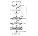
続いて、前記構成を有するナビゲーション装置1においてナビゲーションECU13が実行する分岐点案内処理プログラムについて図6に基づき説明する。図6は本実施形態に係る分岐点案内処理プログラムのフローチャートである。ここで、分岐点案内処理プログラムは車両のACCがONされた後に所定間隔(例えば車両の現在位置の検出周期毎)で繰り返し実行され、案内経路上にある案内分岐点に対する案内を行うプログラムである。尚、以下の図6、図7にフローチャートで示されるプログラムは、ナビゲーション装置1が備えているRAM42やROM43に記憶されており、CPU41により実行される。 Next, a branch point guidance processing program executed by the
先ず、分岐点案内処理プログラムではステップ(以下、Sと略記する)1において、CPU41は、ナビゲーション装置1において設定された案内経路に基づく経路案内が行われているか否か判定する。ここで、案内経路は、出発地(例えば自車の現在位置)からユーザに選択された目的地までの推奨経路であり、経路探索処理の結果に基づいて設定される。また、経路探索処理は、地図情報DB31に記憶されたリンクデータ35やノードデータ36、VICSセンタから取得した交通情報等を用いて、公知のダイクストラ法等により行われる。 First, in step (hereinafter abbreviated as S) 1 in the branch point guidance processing program, the
そして、ナビゲーション装置1において設定された案内経路に基づく経路案内が行われていると判定された場合(S1:YES)には、S2へと移行する。それに対して、ナビゲーション装置1において設定された案内経路に基づく経路案内が行われていないと判定された場合(S1:NO)には、当該分岐点案内処理プログラムを終了する。 And when it determines with the route guidance based on the guidance route set in the
S2においてCPU41は、車両の現在位置を現在位置検出部11の検出結果に基づいて取得する。尚、車両の現在位置を地図データ上で特定するマップマッチング処理についても行う。更に、車両の現在位置は、後述のように高精度ロケーション技術を用いて詳細に特定することが望ましい。ここで、高精度ロケーション技術とは、車両後方のバックカメラ19から取り込んだ白線や路面ペイント情報を画像認識により検出し、更に、白線や路面ペイント情報を予め記憶した地物DB32と照合することにより、走行車線や高精度な車両位置を検出可能にする技術である。 In S <b> 2, the
次に、S3においてCPU41は、ナビゲーション装置1において設定されている案内経路(案内経路中の案内分岐点を含む)を取得する。 Next, in S <b> 3, the
続いて、S4においてCPU41は、前記S2で取得した車両の現在位置と前記S3で取得した案内経路に基づいて、車両の進行方向前方の所定距離以内(例えば、1.47km以内)に案内分岐点が有るか否か判定する。尚、案内分岐点とは、前記したようにナビゲーション装置1に設定された案内経路に従ってナビゲーション装置1が走行の案内を行う際に、右左折指示等の案内を行う対象となる分岐点である。 Subsequently, in S4, the
そして、車両の進行方向前方の所定距離以内に案内分岐点が有ると判定された場合(S4:YES)には、S5へと移行する。それに対して、車両の進行方向前方の所定距離以内に案内分岐点が無いと判定された場合(S4:NO)には、当該分岐点案内処理プログラムを終了する。 If it is determined that there is a guidance branch point within a predetermined distance ahead of the traveling direction of the vehicle (S4: YES), the process proceeds to S5. On the other hand, when it is determined that there is no guidance branch point within a predetermined distance ahead of the traveling direction of the vehicle (S4: NO), the branch point guidance processing program is terminated.
S5においてCPU41は、車両の進行方向前方にある案内分岐点に対する案内が既に行われたか否か判定する。尚、前記S5では、案内分岐点に対する案内の内、特に案内分岐点での右左折等を指示する音声案内が行われたか否かを判定する。 In S5, the
そして、車両の進行方向前方にある案内分岐点に対する案内が既に行われたと判定された場合(S5:YES)には、当該分岐点案内処理プログラムを終了する。それに対して、車両の進行方向前方にある案内分岐点に対する案内が行われていないと判定された場合(S5:NO)には、S6へと移行する。 And when it determines with guidance with respect to the guidance branch point ahead of the advancing direction of a vehicle having already been performed (S5: YES), the said branch point guidance process program is complete | finished. On the other hand, when it is determined that the guidance for the guidance branch point ahead of the traveling direction of the vehicle is not performed (S5: NO), the process proceeds to S6.
S6においてCPU41は、後述の分岐点案内判定処理(図7)を実行する。尚、分岐点案内判定処理は、後述のように車両の進行方向前方に位置する案内分岐点の案内を開始するタイミングとなったか否かを、高精度ロケーション技術を用いて判定し、案内を開始するタイミングとなったと判定した場合に、案内分岐点の案内を開始する処理である。 In S6, the
次に、前記S6において実行される分岐点案内判定処理のサブ処理について図7に基づき説明する。図7は分岐点案内判定処理のサブ処理プログラムのフローチャートである。 Next, a sub-process of the branch point guidance determination process executed in S6 will be described with reference to FIG. FIG. 7 is a flowchart of a sub-processing program for branch point guidance determination processing.
先ず、S11においてCPU41は、車両の進行方向前方に位置する案内分岐点に対する地物テーブル34が作成されているか否か判定する。ここで、地物テーブル34は、後述のS12において作成され、車両の進行方向前方にある案内分岐点を基準にして、該案内分岐点及び手前分岐点にある停止線及び退出側信号機の相対的な位置関係を特定したテーブルである。 First, in S11, the
そして、車両の進行方向前方に位置する案内分岐点に対する地物テーブル34が作成されていると判定された場合(S11:YES)には、S14へと移行する。それに対して、車両の進行方向前方に位置する案内分岐点に対する地物テーブル34が作成されていないと判定された場合(S11:NO)には、S12へと移行する。 And when it determines with the feature table 34 having been produced with respect to the guidance branch point located ahead of the advancing direction of a vehicle (S11: YES), it transfers to S14. On the other hand, when it is determined that the feature table 34 for the guidance branch point located in front of the traveling direction of the vehicle is not created (S11: NO), the process proceeds to S12.
S12においてCPU41は、車両の進行方向前方に位置する案内分岐点と、該案内分岐点の手前側に位置する手前分岐点について、各分岐点の位置情報を地図情報DB31から取得する。また、案内分岐点及び手前分岐点に設置された退出側信号機に関する情報(位置座標、灯数等)を信号機情報38から取得する。更に、案内分岐点及び手前分岐点に配置された停止線(実停止線以外に仮想停止線も含む)に関する情報(位置座標、制御対象物である分岐点までの距離等)について地物DB32(図3)から取得する。そして、取得した各情報に基づいて地物テーブル34を作成する。尚、地物テーブル34の作成対象とする手前分岐点は、車両の現在位置から案内分岐点までにある全ての手前分岐点としても良いし、所定の手前分岐点のみ(例えば第1手前分岐点から第3手前分岐点)としても良い。 In S12, the
ここで、図8は、前記S12において作成される地物テーブル34の一例を示した図である。図8に示す地物テーブル34では、車両71の進行方向前方にある案内分岐点72を基準にして、該案内分岐点72及び第1手前分岐点73、第2手前分岐点74、第3手前分岐点75にある退出側信号機76〜79及び停止線80〜83の相対的な位置関係が記録されている。
例えば、案内分岐点72の退出側信号機76は、3灯式であり、案内分岐点72に対して出発地側と逆方向に10m離れた位置に設置されていることが記録される。また、第2手前分岐点74の停止線82は、「ID:345」の仮想停止線であり、案内分岐点72に対して出発地側に220m離れた位置に設置されていることが記録される。尚、退出側信号機76〜79の案内分岐点72からの相対距離は、例えば案内分岐点72の位置座標と信号機情報38から取得された各退出側信号機76〜79の位置座標とに基づいて算出される。また、停止線80〜83の案内分岐点72からの相対距離は、例えば各分岐点72〜75の位置座標と地物DB32(図3)から取得した各停止線80〜83から制御対象物である各分岐点72〜75までの距離とに基づいて算出される。Here, FIG. 8 is a diagram showing an example of the feature table 34 created in S12. In the feature table 34 shown in FIG. 8, the
For example, it is recorded that the exit
次に、S13においてCPU41は、前記S12で作成された地物テーブル34に基づいて、案内分岐点の案内を行う際の案内フレーズの内容と、案内分岐点の案内を開始する案内開始地点をそれぞれ決定する。例えば、案内経路が車両の進行方向前方にある案内分岐点で左折する経路であった場合には、案内フレーズとして「3つ目の信号を左方向です」、「2つ目の信号を左方向です」、「次の信号を左方向です」がそれぞれ決定される。また、「3つ目の信号を左方向です」との案内には、車両の乗員(特に運転手)から第3手前分岐点の退出側信号機が視認できる状態から視認できなくなる状態へと切り替わる地点を案内開始地点に決定する。同じく、「2つ目の信号を左方向です」との案内には、車両の乗員(特に運転手)から第2手前分岐点の退出側信号機が視認できる状態から視認できなくなる状態へと切り替わる地点を案内開始地点に決定する。同じく、「次の信号を左方向です」との案内には、車両の乗員(特に運転手)から第1手前分岐点の退出側信号機が視認できる状態から視認できなくなる状態へと切り替わる地点を案内開始地点に決定する。 Next, in S13, the
ここで、車両の乗員から手前分岐点の退出側信号機が視認できる状態から視認できなくなる状態へと切り替わる地点は、退出側信号機に対する相対的な位置関係によって特定されるが、その地点は車種毎に(より具体的には車の形状やフロントウィンドウの形状によって)異なる。具体的には、図9に示すように、車両71が走行中に車両71の乗員85の視界から退出側信号機76〜79が外れる地点が案内開始地点となる。そして、案内開始地点の位置は、退出側信号機76〜79から出発地側への離間距離Xによって特定される。ここで、離間距離Xは車種毎に異なる値がデータ記録部12に記録されており、前記S13でCPU41は、データ記録部12から車両情報として離間距離Xを取得し、案内開始地点を決定する。尚、離間距離Xは固定値(例えば5m)としても良い。 Here, the point at which the exit signal at the front branch point from the occupant of the vehicle can be switched to the state where it cannot be identified is specified by the relative positional relationship with the exit signal, but the point is determined for each vehicle type. It depends on the shape of the car and the shape of the front window. Specifically, as shown in FIG. 9, a point where the exit
その後、S14においてCPU41は、前記S12で作成された地物テーブルと前記S2で取得した車両の現在位置に基づいて、車両が手前分岐点の停止線から前後40m以内に位置するか否か判定する。 Thereafter, in S14, the
そして、車両が手前分岐点の停止線から前後40m以内に位置すると判定された場合(S14:YES)には、S15へと移行する。それに対して、車両が手前分岐点の停止線から前後40m以内に位置しないと判定された場合(S14:NO)には、S17へと移行する。 If it is determined that the vehicle is located within 40 m before and after the stop line at the front branch point (S14: YES), the process proceeds to S15. On the other hand, when it is determined that the vehicle is not located within 40 m before and after the stop line at the front branch point (S14: NO), the process proceeds to S17.
S15においてCPU41は、当該分岐点案内処理プログラムと並行して所定間隔で実施されている地物認識処理において、手前分岐点の停止線を認識(検出)したか否か判定する。ここで、地物認識処理は、地物DB32(図3)に記録されている路面標示の位置座標から所定距離以内(例えば40m以内)に車両が位置する場合に、バックカメラ19で撮像した画像から該当する路面標示を認識(検出)する処理である。 In S15, the
そして、手前分岐点の停止線を認識(検出)したと判定された場合(S15:YES)には、S16へと移行する。それに対して、手前分岐点の停止線を認識(検出)していないと判定された場合(S15:NO)には、S17へと移行する。 And when it determines with having recognized (detected) the stop line of a near branch point (S15: YES), it transfers to S16. On the other hand, when it is determined that the stop line at the preceding branch point is not recognized (detected) (S15: NO), the process proceeds to S17.
S16においてCPU41は、認識した手前分岐点の停止線を識別する識別IDを地物DB32から取得し、RAM42に記憶する。尚、新たに手前分岐点の停止線を認識した場合には、認識する度に新たな識別IDに上書きされる。即ち、最も新しく認識した手前分岐点の停止線の識別IDが記憶される。また、手前分岐点の停止線を認識した時点の車両の生涯走行距離についても取得する。尚、生涯走行距離は、車両が製造されてから現在までの累積走行距離であり、車両に搭載されたメモリ等から取得する。そして、取得した車両の生涯走行距離についても同様にRAM42に記憶する。 In S <b> 16, the
次に、S17においてCPU41は、“最も新しく認識した手前分岐点の停止線から次の案内を行う案内開始地点までの距離M”を算出する。具体的には、前記S12で作成された地物テーブル34(図8)と前記S13で決定された案内開始地点とに基づいて算出する。
以下に、前記S17における距離Mの算出方法について具体例を挙げて説明する。
例えば、図10では、案内分岐点72へと向かう車両71が、第3手前分岐点75の停止線83を直前に認識しており、次に「2つ目の信号を左方向です」との案内を行う場合について示す。図10に示す例では、次の案内を行う案内開始地点は上述したように第2手前分岐点74の退出側信号機78から所定距離X手前の地点となる。従って、CPU41は、地物テーブル34から先ず、停止線83から案内分岐点72までの距離Aと、退出側信号機78から案内分岐点72までの距離Bをそれぞれ取得する。そして、以下の式(1)により距離Mを算出する。
M=A−B−X・・・・(1)Next, in S <b> 17, the
Hereinafter, the calculation method of the distance M in S17 will be described with a specific example.
For example, in FIG. 10, the
M = A−B−X (1)
続いて、S18においてCPU41は、“最も新しく認識した手前分岐点の停止線から車両の現在位置までの距離N”を算出する。具体的には、前記S12で作成された地物テーブル34(図8)と、前記S16で記憶した停止線の認識時点の車両の生涯走行距離と、新たに取得した現時点での車両の生涯走行距離と、停止線の画像認識処理の結果とに基づいて算出する。
以下に、前記S18における距離Nの算出方法について具体例を挙げて説明する。
先ず、CPU41は、車両のバックカメラ19によって停止線を認識した際の停止線から車両(特に運転席)までの距離を算出する。図11は停止線83を撮像する車両を示した側面図であり、図12は車両のバックカメラ19によって停止線83を撮像した撮像画像88を示した図である。Subsequently, in S <b> 18, the
Hereinafter, the calculation method of the distance N in S18 will be described with a specific example.
First, the
バックカメラ19は、図11に示すように車両71の後バンパー89付近から後方を撮像できるように光軸Lを水平から所定角度θ(例えば45度)下方向に向けるように取り付けられており、撮像範囲が固定されている。従って、バックカメラ19によって撮像された図12に示す撮像画像中の画像データの位置(具体的には下縁からの画素数)から、被写体までの距離を計算することができる。 As shown in FIG. 11, the
ここで、停止線を含む各種路面標示には車両との距離を計測する為の測定開始点が予め定義され、路面標示を形成するライン(境界線)の角部や先端部に設けられている。例えば、停止線83では、停止線83と路面90との車両側の境界中央部分に設けられている。従って、CPU41は、図7に示す停止線83を撮像した撮像画像中において、測定開始点Yの位置(具体的には下縁から測定開始点までの画素数)からバックカメラ19と測定開始点Yの間の距離D1を算出することが可能となる。 Here, in various road markings including a stop line, a measurement start point for measuring a distance from the vehicle is defined in advance, and is provided at a corner or a tip of a line (boundary line) forming the road marking. . For example, the
また、CPU41は、バックカメラ19の位置から車両(特に運転席)までの距離D2を取得する。尚、バックカメラ19の位置から車両(特に運転席)までの距離D2は、車両情報として予めデータ記録部12に記憶されている。 Further, the
その後、CPU41は、現時点で新たに取得した車両の生涯走行距離と、前記S16で記憶した停止線の認識時点の車両の生涯走行距離との差分距離Eを算出する。尚、差分距離Eは、最も新しく停止線を認識してから現在までの車両の走行距離に相当する。そして、図13に示すように以下の式(2)により距離Nを算出する。
N=D1+D2+E・・・・(2)Thereafter, the
N = D1 + D2 + E (2)
次に、S19においてCPU41は、前記S18で算出された“最も新しく認識した手前分岐点の停止線から車両の現在位置までの距離N”が、前記S17で算出された“最も新しく認識した手前分岐点の停止線から次の案内を行う案内開始地点までの距離M”以上となったか否かを判定する。具体的に、前記S19では、前記S13で決定された案内開始地点を車両が通過したか否かが判定されることとなる。 Next, in S19, the
そして、前記S13で決定された案内開始地点を車両が通過したと判定された場合(S19:YES)には、S20へと移行する。それに対して、前記S13で決定された案内開始地点を車両が通過していないと判定された場合(S19:NO)には、当該分岐点案内処理プログラムを終了する。 And when it determines with the vehicle having passed the guidance start point determined by said S13 (S19: YES), it transfers to S20. On the other hand, when it is determined that the vehicle has not passed the guidance start point determined in S13 (S19: NO), the branch point guidance processing program is terminated.
S20においてCPU41は、前記S13で決定された案内フレーズに基づいて、案内分岐点に関する案内を行う。具体的には、案内分岐点と車両の案内分岐点の退出方向とを特定する案内(即ち、車両が案内分岐点から退出する退出道路を特定させる為の案内)を行う。例えば、「2つ目の信号を左(右)方向です」とのフレーズをスピーカ16から出力する。更に、案内分岐点が車両の所定距離以内(例えば300m)に接近した場合には、案内分岐点付近の拡大図や車両の案内分岐点における進行方向について液晶ディスプレイ15に表示する。
その結果、案内分岐点及び該案内分岐点から車両が退出する道路をユーザに正確に特定させることが可能となる。In S20, the
As a result, it becomes possible for the user to accurately specify the guidance branch point and the road from which the vehicle exits from the guidance branch point.
以上詳細に説明した通り、本実施形態に係るナビゲーション装置1、ナビゲーション装置1を用いた移動案内方法及びナビゲーション装置1で実行されるコンピュータプログラムによれば、手前分岐点に設置された退出側信号機に対する相対位置によって特定される案内開始地点と、その案内開始地点で開始する案内分岐点の案内フレーズをそれぞれ決定するとともに(S13)、停止線を認識対象とした高精度ロケーションシステムを用いて、最も新しく認識した停止線から車両の現在位置までの距離を算出し(S18)、算出した距離を用いて車両が案内開始地点を通過したか否か判定し(S19)、車両が案内開始地点を通過したと判定された時に、案内分岐点の案内を開始する(S20)ので、案内の内容に基づく適切なタイミングで案内分岐点の案内を開始することが可能となる。従って、ユーザに案内分岐点を正確に特定させることが可能となる。
また、停止線を検出した後の車両の移動距離Eと、停止線から案内開始地点までの地物距離Mとに基づいて、車両が案内開始地点を通過したか否か判定するので、手前分岐点に設置された停止線を用いて、車両と案内開始地点との位置関係を正確に特定することが可能となる。その結果、車両が案内開始地点を通過した正確なタイミングで案内分岐点の案内を開始することが可能となる。
また、停止線を検出した際の停止線から車両までの距離(D1+D2)に停止線を検出した後の車両の移動距離Eを加算した距離Nが地物距離M以上となった場合に、車両が案内開始地点を通過したと判定する(S19)ので、車両がバックカメラ19により停止線を撮像することによって、停止線を撮像した後の車両の位置を、該停止線に対する相対位置により正確に特定することが可能となる。その結果、車両と案内開始地点との位置関係を正確に特定することが可能となり、車両が案内開始地点を通過した正確なタイミングで案内分岐点の案内を開始することが可能となる。
また、停止線と該停止線の位置情報とが対応付けられた地物情報に基づいて、停止線から案内開始地点までの地物距離Mを取得するので、別途に地物距離Mを算出する為の特別な処理を行うことなく、地物情報から地物距離Mを容易に算出することが可能となる。
また、停止線は信号機の設置された分岐点周辺の路面に描かれている可能性が極めて高いので、車両が手前分岐点を通過する際に、車両と案内開始地点との位置関係を確実に特定することが可能となる。
また、車両の乗員から手前分岐点の退出側信号機が視認できる状態から視認できなくなる状態へと切り替わる切替地点を案内開始地点とするので、手前分岐点の退出側信号機が視認できなくなった時点で案内分岐点の案内を開始することが可能となる。その結果、案内内容に基づく適切なタイミングで案内分岐点の案内を開始することが可能となる。特に信号機を用いた案内(例えば、車両の現在位置から案内分岐点までにある信号機(又は信号機の設置された分岐点)の数を用いた案内)を行う場合には、その効果は顕著なものとなる。As described above in detail, according to the
Further, since it is determined whether or not the vehicle has passed the guidance start point based on the moving distance E of the vehicle after detecting the stop line and the feature distance M from the stop line to the guidance start point, It becomes possible to accurately specify the positional relationship between the vehicle and the guidance start point using the stop line installed at the point. As a result, it is possible to start guidance at the guidance branch point at an accurate timing when the vehicle passes the guidance start point.
Further, when the distance N obtained by adding the moving distance E of the vehicle after detecting the stop line to the distance (D1 + D2) from the stop line to the vehicle when the stop line is detected becomes the feature distance M or more, Is determined to have passed the guidance start point (S19), the vehicle captures the stop line with the
Further, since the feature distance M from the stop line to the guidance start point is acquired based on the feature information in which the stop line and the position information of the stop line are associated with each other, the feature distance M is calculated separately. Therefore, it is possible to easily calculate the feature distance M from the feature information without performing special processing.
In addition, the possibility that the stop line is drawn on the road surface around the branch point where the traffic signal is installed is very high, so when the vehicle passes the front branch point, the positional relationship between the vehicle and the guidance start point is ensured. It becomes possible to specify.
Also, since the switching point where the exit signal at the front branch point is visible from the vehicle occupant to the state where it is no longer visible is set as the guidance start point, guidance is provided when the exit signal at the front branch point becomes invisible. It becomes possible to start the guidance of the branch point. As a result, it is possible to start guidance at the guidance branch point at an appropriate timing based on the guidance content. In particular, when performing guidance using traffic lights (for example, guidance using the number of traffic lights (or branch points where traffic lights are installed) from the current position of the vehicle to the guidance branch point), the effect is remarkable. It becomes.
尚、本発明は前記実施形態に限定されるものではなく、本発明の要旨を逸脱しない範囲内で種々の改良、変形が可能であることは勿論である。
例えば、本実施形態ではナビゲーション装置1による案内分岐点の案内をスピーカ16から音声案内により出力することにより行う構成としているが、液晶ディスプレイ15に文章を表示することにより案内を行う構成としても良い。Note that the present invention is not limited to the above-described embodiment, and various improvements and modifications can be made without departing from the scope of the present invention.
For example, in the present embodiment, the guidance branch point guidance by the
また、本実施形態では、車両の現在位置を特定する為に認識対象とする地物として、特に停止線を用いているが、停止線以外の路面標示を用いても良い。また、路面標示以外の
障害物、建造物、道路標識等を用いても良い。但し、認識対象とする地物は、手前分岐点よりも出発地側にあり、且つ案内分岐点の手前側に所定間隔で複数個存在することが望ましい。In this embodiment, a stop line is used as a feature to be recognized in order to specify the current position of the vehicle. However, a road marking other than the stop line may be used. Further, obstacles other than road markings, buildings, road signs, etc. may be used. However, it is desirable that a plurality of features to be recognized be present at the departure point side from the front branch point and at a predetermined interval on the front side from the guide branch point.
また、本実施形態では、案内開始地点を、車両の乗員から手前分岐点の退出側信号機が視認できる状態から視認できなくなる状態へと切り替わる切替地点に設定しているが、車両の乗員から手前分岐点の退出側信号機が視認できない状態となる地点であれば、他の地点としても良い。例えば、切替地点から所定距離だけ案内分岐点側の地点としても良い。また、手前分岐点の退出側信号機の設置された位置を案内開始地点としても良い。 Further, in this embodiment, the guidance start point is set as a switching point where the vehicle occupant switches from the state in which the exit side traffic light at the front branch point can be visually recognized to the state in which the vehicle cannot be viewed. Other points may be used as long as the point leaving signal is not visible. For example, it may be a point on the guidance branch point side by a predetermined distance from the switching point. Further, the guidance start point may be a position where the exit side traffic signal is installed at the front branch point.
また、本実施形態では信号機情報38として分岐点の周辺に配置された全ての信号機に関する情報を記憶する構成としているが、分岐点からの退出方向毎に最も退出側にある信号機に関する情報のみを記憶する構成としても良い。その場合には、本実施形態中の進入側信号機を退出側信号機に置き換えることによって、本発明を実施することが可能である。更に、分岐点への進入方向毎に最も進入側にある信号機に関する情報のみを記憶する構成としても良い。また、信号機の代わりに停止線に関する情報を記憶する構成としても良い。その場合には、本実施形態中の進入側信号機及び退出側信号機を停止線に置き換えることによって、本発明を実施することが可能である。尚、信号機の代わりに停止線を用いる場合であっても、案内は信号機や分岐点を用いて行うことが望ましい。 In the present embodiment, the
また、本実施形態では、案内分岐点の案内として、車両の現在位置から車両の現在位置から案内分岐点までにある信号機(又は信号機の設置された分岐点)の数を用いた案内を行うこととしているが、他の案内を行うようにしても良い。但し、特に信号機を用いた案内を行う場合において、本願発明の効果は顕著なものとなる。 In the present embodiment, as guidance for the guidance branch point, guidance is performed using the number of traffic lights (or branch points where traffic lights are installed) from the current position of the vehicle to the guidance branch point. However, other guidance may be provided. However, the effect of the present invention is remarkable especially when performing guidance using a traffic light.
また、本発明はナビゲーション装置以外に、案内経路に基づく経路案内を行う機能を有する装置に対して適用することが可能である。例えば、携帯電話機やPDA等の携帯端末、パーソナルコンピュータ、携帯型音楽プレイヤ等(以下、携帯端末等という)に適用することも可能である。また、サーバと携帯端末等から構成されるシステムに対しても適用することが可能となる。その場合には、上述した分岐点案内処理プログラム(図6、図7)の各ステップは、サーバと携帯端末等のいずれが実施する構成としても良い。また、本発明を携帯端末等に適用する場合には、車両以外の移動体、例えば、携帯端末等のユーザや2輪車等に対する走行案内を行う場合もある。 In addition to the navigation device, the present invention can be applied to a device having a function of performing route guidance based on a guidance route. For example, the present invention can be applied to a portable terminal such as a cellular phone or a PDA, a personal computer, a portable music player, etc. (hereinafter referred to as a portable terminal or the like). Further, the present invention can be applied to a system including a server and a mobile terminal. In that case, each step of the above-described branch point guidance processing program (FIGS. 6 and 7) may be configured to be implemented by either a server or a portable terminal. In addition, when the present invention is applied to a mobile terminal or the like, travel guidance may be given to a moving body other than a vehicle, for example, a user of a mobile terminal or a two-wheeled vehicle.
1 ナビゲーション装置
13 ナビゲーションECU
19 バックカメラ
31 地図情報DB
32 地物DB
34 地物テーブル
41 CPU
42 RAM
43 ROM
71 車両
72 案内分岐点
73〜75 手前分岐点
77〜79 退出側信号機
81〜83 停止線1
19
32 Feature DB
34 Feature Table 41 CPU
42 RAM
43 ROM
71
Claims (9)
Translated fromJapanese前記案内分岐点よりも前記案内経路の出発地側に存在する手前分岐点の退出側信号機の位置を取得する信号機位置取得手段と、
前記車両の位置を取得する車両位置取得手段と、
前記車両に関する車両情報を取得する車両情報取得手段と、
前記車両情報に基づいて、前記車両の乗員から前記手前分岐点の前記退出側信号機が視認できる状態から視認できなくなる状態へと切り替わる切替地点を特定する切替地点特定手段と、
前記切替地点を前記案内分岐点の案内を開始する地点である案内開始地点として取得する案内開始地点取得手段と、
前記車両の位置と前記案内開始地点の位置とに基づいて、前記車両が前記案内開始地点を通過したか否か判定する通過判定手段と、
前記通過判定手段により前記車両が前記案内開始地点を通過したと判定された時に、前記案内分岐点の案内を開始する分岐点案内手段と、を有することを特徴とする移動案内システム。A guide route for guiding thetravel of thevehicle , a guide route setting means for setting a guide branch point on the guide route,
Traffic light position acquisition means for acquiring the position of the exit side traffic light at the near branch point existing on the departure side of the guide route from the guide branch point;
Avehicle position acquiring unit that acquires a position of thevehicle,
Vehicle information acquisition means for acquiring vehicle information relating to the vehicle;
Based on the vehicle information, a switching point specifying means for specifying a switching point for switching from a state in which the exit side traffic light at the front branch point can be visually recognized from an occupant of the vehicle,
Guidance start point acquisition meansfor acquiring theswitching point as a guidance start point that is a point at which guidance of the guidance branch point is started;
Passage determining means for determining whether or not thevehicle has passed the guidance start point based on the position of thevehicle and the position of the guidance start point;
And a branching point guidance unit that starts guidance of the guidance branching point when the passage determination unit determines that thevehicle has passed the guidance start point.
前記地物検出手段により前記地物を検出した後の前記車両の走行距離を算出する距離算出手段と、
前記地物から前記案内開始地点までの距離である地物距離を取得する地物距離取得手段と、を有し、
前記通過判定手段は、前記走行距離と前記地物距離とに基づいて、前記車両が前記案内開始地点を通過したか否か判定することを特徴とする請求項1に記載の移動案内システム。A feature detection means for detecting a feature present on the departure side of the guide route at the front branch point;
Distance calculating means for calculating atravel distance of thevehicle after the feature is detected by the feature detecting means;
A feature distance acquisition means for acquiring a feature distance that is a distance from the feature to the guidance start point;
The movement guidance system according to claim 1, wherein the passage determination unit determines whether or not thevehicle has passed the guidance start point based on thetravel distance and the feature distance.
前記通過判定手段は、前記地物検出手段により前記地物を検出した際の前記地物から前記車両までの距離に前記走行距離を加算した距離が前記地物距離以上となった場合に、前記車両が前記案内開始地点を通過したと判定することを特徴とする請求項2に記載の移動案内システム。The feature detecting means, based on the installed image captured from the imaging means to thevehicle, and detects the feature of thevehicle is formed on the road to travel,
The passage determining means, when the distance obtained by adding thetravel distance to the distance from the feature to thevehicle when the feature is detected by the feature detection means is equal to or greater than the feature distance, The movement guidance system according to claim 2, wherein it is determined that thevehicle has passed the guidance start point.
前記地物距離取得手段は、前記地物情報と前記手前分岐点の前記退出側信号機の位置情報とに基づいて前記地物距離を取得することを特徴とする請求項2又は請求項3に記載の移動案内システム。Comprising feature information acquisition means for acquiring feature information in which the feature detected by the feature detection means is associated with position information of the feature;
The said feature distance acquisition means acquires the said feature distance based on the said feature information and the positional information on the said exit side signal of the said front branch point, The said feature distance is characterized by the above-mentioned. Travel guidance system.
前記案内分岐点よりも前記案内経路の出発地側に存在する手前分岐点の退出側信号機の位置を取得する信号機位置取得手段と、
前記車両の位置を取得する車両位置取得手段と、
前記車両に関する車両情報を取得する車両情報取得手段と、
前記車両情報に基づいて、前記車両の乗員から前記手前分岐点の前記退出側信号機が視認できる状態から視認できなくなる状態へと切り替わる切替地点を特定する切替地点特定手段と、
前記切替地点を前記案内分岐点の案内を開始する地点である案内開始地点として取得する案内開始地点取得手段と、
前記車両の位置と前記案内開始地点の位置とに基づいて、前記車両が前記案内開始地点を通過したか否か判定する通過判定手段と、
前記通過判定手段により前記車両が前記案内開始地点を通過したと判定された時に、前記案内分岐点の案内を開始する分岐点案内手段と、を有することを特徴とする移動案内装置。A guide route for guiding thetravel of thevehicle , a guide route setting means for setting a guide branch point on the guide route,
Traffic light position acquisition means for acquiring the position of the exit side traffic light at the near branch point existing on the departure side of the guide route from the guide branch point;
Avehicle position acquiring unit that acquires a position of thevehicle,
Vehicle information acquisition means for acquiring vehicle information relating to the vehicle;
Based on the vehicle information, a switching point specifying means for specifying a switching point for switching from a state in which the exit side traffic light at the front branch point can be visually recognized from an occupant of the vehicle,
Guidance start point acquisition meansfor acquiring theswitching point as a guidance start point that is a point at which guidance of the guidance branch point is started;
Passage determining means for determining whether or not thevehicle has passed the guidance start point based on the position of thevehicle and the position of the guidance start point;
And a branch point guide unit that starts guiding the guide branch point when the passage determination unit determines that thevehicle has passed the guidance start point.
信号機位置取得手段が、前記案内分岐点よりも前記案内経路の出発地側に存在する手前分岐点の退出側信号機の位置を取得するステップと、
車両位置取得手段が、前記車両の位置を取得するステップと、
車両情報取得手段が、前記車両に関する車両情報を取得するステップと、
切替地点特定手段が、前記車両情報に基づいて、前記車両の乗員から前記手前分岐点の前記退出側信号機が視認できる状態から視認できなくなる状態へと切り替わる切替地点を特定するステップと、
案内開始地点取得手段が、前記切替地点を前記案内分岐点の案内を開始する地点である案内開始地点として取得するステップと、
通過判定手段が、前記車両の位置と前記案内開始地点の位置とに基づいて、前記車両が前記案内開始地点を通過したか否か判定するステップと、
分岐点案内手段が、前記通過判定手段により前記車両が前記案内開始地点を通過したと判定された時に、前記案内分岐点の案内を開始するステップと、を有することを特徴とする移動案内方法。Guidance route setting means, andaway step to set the guidance branch point on the guidance route and the guide path for guiding thetraveling of thevehicle,
Traffic signal position acquisition unit, andLuz step to obtain the position of the exit-side traffic of prior branch points present in the starting point side of the guidance route than the guidance branch point,
Vehicle position acquisition means includesLuz step to obtain the position of thevehicle,
Vehicle information acquisition means acquires vehicle information about the vehicle;
A switching point identifying means, based on the vehicle information, identifying a switching point at which the occupant of the vehicle switches from a state in which the exit-side traffic light at the front branch point is visible to a state in which it is not visible;
Guidance starting point acquisition means includesLuz step to obtainas a guidance start point isthe switch point is a point to start guiding the guidance branch point,
Passing judgment means, on the basis of the position of thevehicle and the position of the guidance starting point, andaway step to determine whether thevehicle has passed the guidance starting point,
Junction guiding means, moving the guide, characterized in that it has a, andanswering step to start, the guidance of the guide branch point when thevehicle is determined to have passed through the guidance starting point by the passing determiningmeans Method.
車両の走行を案内する案内経路と該案内経路上の案内分岐点を設定する案内経路設定手段と、
前記案内分岐点よりも前記案内経路の出発地側に存在する手前分岐点の退出側信号機の位置を取得する信号機位置取得手段と、
前記車両の位置を取得する車両位置取得手段と、
前記車両に関する車両情報を取得する車両情報取得手段と、
前記車両情報に基づいて、前記車両の乗員から前記手前分岐点の前記退出側信号機が視認できる状態から視認できなくなる状態へと切り替わる切替地点を特定する切替地点特定手段と、
前記切替地点を前記案内分岐点の案内を開始する地点である案内開始地点として取得する案内開始地点取得手段と、
前記車両の位置と前記案内開始地点の位置とに基づいて、前記車両が前記案内開始地点を通過したか否か判定する通過判定手段と、
前記通過判定手段により前記車両が前記案内開始地点を通過したと判定された時に、前記案内分岐点の案内を開始する分岐点案内手段と、
して機能させる為のコンピュータプログラム。The computer,
A guide route for guiding thetravel of thevehicle , a guide route settingmeans for setting a guide branch point on the guide route,
Traffic light position acquisitionmeans for acquiring the position of the exit side traffic light at the near branch point existing on the departure side of the guide route from the guide branch point;
Avehicle position acquiringunit that acquires a position of thevehicle,
Vehicle information acquisition means for acquiring vehicle information relating to the vehicle;
Based on the vehicle information, a switching point specifying means for specifying a switching point for switching from a state in which the exit side traffic light at the front branch point can be visually recognized from an occupant of the vehicle,
Guidance start point acquisitionmeansfor acquiring theswitching point as a guidance start point that is a point at which guidance of the guidance branch point is started;
Passage determiningmeans for determining whether or not thevehicle has passed the guidance start point based on the position of thevehicle and the position of the guidance start point;
A branch point guideunit that starts guiding the guide branch point when the passage determinationunit determines that thevehicle has passed the guidance start point;
Computer programto make it function .
Priority Applications (4)
| Application Number | Priority Date | Filing Date | Title |
|---|---|---|---|
| JP2011147245AJP5729176B2 (en) | 2011-07-01 | 2011-07-01 | Movement guidance system, movement guidance apparatus, movement guidance method, and computer program |
| CN201210200300.5ACN102853827B (en) | 2011-07-01 | 2012-06-14 | Mobile guiding system, mobile guide, mobile bootstrap technique |
| EP20120172120EP2541208B1 (en) | 2011-07-01 | 2012-06-15 | Travel guidance apparatus, travel guidance method, and computer program product |
| US13/538,464US9062987B2 (en) | 2011-07-01 | 2012-06-29 | Travel guidance system, travel guidance apparatus, travel guidance method, and computer program |
Applications Claiming Priority (1)
| Application Number | Priority Date | Filing Date | Title |
|---|---|---|---|
| JP2011147245AJP5729176B2 (en) | 2011-07-01 | 2011-07-01 | Movement guidance system, movement guidance apparatus, movement guidance method, and computer program |
Publications (2)
| Publication Number | Publication Date |
|---|---|
| JP2013015363A JP2013015363A (en) | 2013-01-24 |
| JP5729176B2true JP5729176B2 (en) | 2015-06-03 |
Family
ID=46245519
Family Applications (1)
| Application Number | Title | Priority Date | Filing Date |
|---|---|---|---|
| JP2011147245AActiveJP5729176B2 (en) | 2011-07-01 | 2011-07-01 | Movement guidance system, movement guidance apparatus, movement guidance method, and computer program |
Country Status (4)
| Country | Link |
|---|---|
| US (1) | US9062987B2 (en) |
| EP (1) | EP2541208B1 (en) |
| JP (1) | JP5729176B2 (en) |
| CN (1) | CN102853827B (en) |
Cited By (1)
| Publication number | Priority date | Publication date | Assignee | Title |
|---|---|---|---|---|
| CN105355065A (en)* | 2015-10-23 | 2016-02-24 | 广东欧珀移动通信有限公司 | A navigation reminder method and device |
Families Citing this family (14)
| Publication number | Priority date | Publication date | Assignee | Title |
|---|---|---|---|---|
| DE112012001799B4 (en)* | 2011-04-21 | 2019-04-25 | Mitsubishi Electric Corporation | Drive assistance device |
| DE102012018212A1 (en)* | 2012-09-14 | 2014-03-20 | Audi Ag | Recording traffic and accident data at traffic junctions |
| US9126534B2 (en)* | 2013-03-14 | 2015-09-08 | Ford Global Technologies, Llc | Automated camera wash for vehicles |
| DE102014011796A1 (en)* | 2014-08-08 | 2016-02-11 | Daimler Ag | Method and device for moving a vehicle to a destination position |
| CN104236576A (en)* | 2014-09-17 | 2014-12-24 | 沈阳美行科技有限公司 | Method for early displaying magnification map for navigation equipment by simple guide click |
| CN105357440B (en)* | 2015-11-27 | 2018-10-12 | 苏州佳世达电通有限公司 | focusing system and focusing method |
| US20190227561A1 (en)* | 2016-03-09 | 2019-07-25 | Yanmar Co., Ltd. | Work vehicle and travel region specifying device |
| US10297151B2 (en)* | 2016-05-16 | 2019-05-21 | Ford Global Technologies, Llc | Traffic lights control for fuel efficiency |
| US10181263B2 (en) | 2016-11-29 | 2019-01-15 | Here Global B.V. | Method, apparatus and computer program product for estimation of road traffic condition using traffic signal data |
| DE102017207243A1 (en)* | 2017-04-28 | 2018-10-31 | Continental Automotive Gmbh | Method and device for generating dynamic indications about a change of a route guidance |
| CN111341134A (en)* | 2018-12-18 | 2020-06-26 | 上海擎感智能科技有限公司 | Lane line guide prompting method, cloud server and vehicle |
| JP7205695B2 (en)* | 2019-02-18 | 2023-01-17 | トヨタ自動車株式会社 | driving support system |
| US11769337B2 (en)* | 2019-11-12 | 2023-09-26 | Nissan Motor Co., Ltd. | Traffic signal recognition method and traffic signal recognition device |
| TWI825468B (en)* | 2021-08-25 | 2023-12-11 | 財團法人資訊工業策進會 | Navigation apparatus and method |
Family Cites Families (23)
| Publication number | Priority date | Publication date | Assignee | Title |
|---|---|---|---|---|
| US5177685A (en)* | 1990-08-09 | 1993-01-05 | Massachusetts Institute Of Technology | Automobile navigation system using real time spoken driving instructions |
| JP3191505B2 (en)* | 1993-07-12 | 2001-07-23 | トヨタ自動車株式会社 | Route guidance device for vehicles |
| JP2822962B2 (en)* | 1995-12-14 | 1998-11-11 | 住友電気工業株式会社 | Intersection guidance device |
| JPH1016555A (en)* | 1996-07-05 | 1998-01-20 | Mitsubishi Motors Corp | Sun visor for vehicles |
| JP3220408B2 (en) | 1997-03-31 | 2001-10-22 | 富士通テン株式会社 | Route guidance device |
| JPH10300502A (en)* | 1997-04-22 | 1998-11-13 | Mitsubishi Electric Corp | Travel information notification device |
| JPH11344353A (en)* | 1999-04-02 | 1999-12-14 | Aisin Aw Co Ltd | Navigator for vehicles |
| JP4543541B2 (en)* | 2000-11-17 | 2010-09-15 | ソニー株式会社 | Navigation device, voice guidance method, route guidance method, storage medium |
| JP4506313B2 (en)* | 2004-07-09 | 2010-07-21 | アイシン・エィ・ダブリュ株式会社 | Navigation device |
| JP2007078573A (en)* | 2005-09-15 | 2007-03-29 | Denso Corp | Route guide apparatus and program |
| WO2007063906A1 (en)* | 2005-11-30 | 2007-06-07 | Aisin Aw Co., Ltd. | Route guidance system and route guidance method |
| JP4470873B2 (en)* | 2005-11-30 | 2010-06-02 | アイシン・エィ・ダブリュ株式会社 | Route guidance system and route guidance method |
| JP2007232573A (en)* | 2006-03-01 | 2007-09-13 | Pioneer Electronic Corp | Vehicle-mounted navigation system, guidance information providing method, and program |
| US8078379B2 (en)* | 2006-09-18 | 2011-12-13 | Guixian Lu | Traffic light prediction system |
| JP4830956B2 (en)* | 2007-04-13 | 2011-12-07 | 株式会社デンソー | Vehicle visibility determination device and program for vehicle visibility determination device |
| JP4561769B2 (en) | 2007-04-27 | 2010-10-13 | アイシン・エィ・ダブリュ株式会社 | Route guidance system and route guidance method |
| JP5163077B2 (en)* | 2007-11-27 | 2013-03-13 | アイシン・エィ・ダブリュ株式会社 | Route guidance system and program |
| JP2009250622A (en)* | 2008-04-01 | 2009-10-29 | Pioneer Electronic Corp | Navigation device, route guiding method, and route guiding program |
| JP5094754B2 (en)* | 2009-01-26 | 2012-12-12 | 株式会社デンソーアイティーラボラトリ | Information providing apparatus, information providing method, and program |
| US8370060B2 (en)* | 2009-08-28 | 2013-02-05 | Navteq B.V. | Method of operating a navigation system to provide route guidance |
| US20110098910A1 (en)* | 2009-10-22 | 2011-04-28 | Nokia Corporation | Method and apparatus for intelligent guidance using markers |
| US20110130956A1 (en)* | 2009-11-30 | 2011-06-02 | Nokia Corporation | Method and apparatus for presenting contextually appropriate navigation instructions |
| CN101900571A (en)* | 2010-08-13 | 2010-12-01 | 深圳市凯立德计算机系统技术有限公司 | Display method of navigation information and navigation apparatus |
- 2011
- 2011-07-01JPJP2011147245Apatent/JP5729176B2/enactiveActive
- 2012
- 2012-06-14CNCN201210200300.5Apatent/CN102853827B/ennot_activeExpired - Fee Related
- 2012-06-15EPEP20120172120patent/EP2541208B1/ennot_activeNot-in-force
- 2012-06-29USUS13/538,464patent/US9062987B2/ennot_activeExpired - Fee Related
Cited By (1)
| Publication number | Priority date | Publication date | Assignee | Title |
|---|---|---|---|---|
| CN105355065A (en)* | 2015-10-23 | 2016-02-24 | 广东欧珀移动通信有限公司 | A navigation reminder method and device |
Also Published As
| Publication number | Publication date |
|---|---|
| EP2541208B1 (en) | 2015-03-04 |
| US9062987B2 (en) | 2015-06-23 |
| EP2541208A2 (en) | 2013-01-02 |
| JP2013015363A (en) | 2013-01-24 |
| CN102853827A (en) | 2013-01-02 |
| US20130006523A1 (en) | 2013-01-03 |
| EP2541208A3 (en) | 2014-07-02 |
| CN102853827B (en) | 2016-12-21 |
Similar Documents
| Publication | Publication Date | Title |
|---|---|---|
| JP5729176B2 (en) | Movement guidance system, movement guidance apparatus, movement guidance method, and computer program | |
| EP2612112B9 (en) | Travel guidance system, travel guidance apparatus, travel guidance method and computer program | |
| JP2013024685A (en) | Traveling guide system, traveling guide device, traveling guide method, and computer program | |
| JP5811666B2 (en) | Stop line detection system, stop line detection device, stop line detection method, and computer program | |
| JP2013019681A (en) | Travel guiding system, travel guiding device, travel guiding method, and computer system | |
| JP5712847B2 (en) | Traffic light increase / decrease detection system, traffic light increase / decrease detection device, traffic light increase / decrease detection method, and computer program | |
| JP2014145666A (en) | Travel guide system, travel guide method, and computer program | |
| JP5899691B2 (en) | Moving body position detection system, moving body position detection apparatus, moving body position detection method, and computer program | |
| JP5691915B2 (en) | Movement guidance system, movement guidance apparatus, movement guidance method, and computer program | |
| JP5794023B2 (en) | Stop line detection system, stop line detection device, stop line detection method, and computer program | |
| JP5720517B2 (en) | Stop line detection system, stop line detection device, stop line detection method, and computer program | |
| JP5810721B2 (en) | Movement guidance system, movement guidance apparatus, movement guidance method, and computer program | |
| JP5831016B2 (en) | Movement guidance system, movement guidance apparatus, movement guidance method, and computer program | |
| JP5716564B2 (en) | Movement guidance system, movement guidance apparatus, movement guidance method, and computer program | |
| JP5708326B2 (en) | Movement guidance system, movement guidance apparatus, movement guidance method, and computer program | |
| JP5786523B2 (en) | Movement guidance system, movement guidance apparatus, movement guidance method, and computer program | |
| JP5794024B2 (en) | Stop line detection system, stop line detection device, stop line detection method, and computer program | |
| JP5741288B2 (en) | Movement guidance system, movement guidance apparatus, movement guidance method, and computer program | |
| JP5712844B2 (en) | Moving body position detection system, moving body position detection apparatus, moving body position detection method, and computer program | |
| JP5760802B2 (en) | Signal information update system, signal information update device, signal information update method, and computer program | |
| JP5708325B2 (en) | Movement guidance system, movement guidance apparatus, movement guidance method, and computer program | |
| JP5786522B2 (en) | Movement guidance system, movement guidance apparatus, movement guidance method, and computer program | |
| JP5786519B2 (en) | Movement guidance system, movement guidance apparatus, movement guidance method, and computer program | |
| JP2014145672A (en) | Travel guide system, travel guide method, and computer program |
Legal Events
| Date | Code | Title | Description |
|---|---|---|---|
| A621 | Written request for application examination | Free format text:JAPANESE INTERMEDIATE CODE: A621 Effective date:20140310 | |
| A977 | Report on retrieval | Free format text:JAPANESE INTERMEDIATE CODE: A971007 Effective date:20141119 | |
| A131 | Notification of reasons for refusal | Free format text:JAPANESE INTERMEDIATE CODE: A131 Effective date:20141224 | |
| A521 | Written amendment | Free format text:JAPANESE INTERMEDIATE CODE: A523 Effective date:20150216 | |
| TRDD | Decision of grant or rejection written | ||
| A01 | Written decision to grant a patent or to grant a registration (utility model) | Free format text:JAPANESE INTERMEDIATE CODE: A01 Effective date:20150310 | |
| A61 | First payment of annual fees (during grant procedure) | Free format text:JAPANESE INTERMEDIATE CODE: A61 Effective date:20150323 | |
| R150 | Certificate of patent or registration of utility model | Ref document number:5729176 Country of ref document:JP Free format text:JAPANESE INTERMEDIATE CODE: R150 |