JP5728215B2 - Audio processing apparatus and method, and imaging apparatus - Google Patents
Audio processing apparatus and method, and imaging apparatusDownload PDFInfo
- Publication number
- JP5728215B2 JP5728215B2JP2010277419AJP2010277419AJP5728215B2JP 5728215 B2JP5728215 B2JP 5728215B2JP 2010277419 AJP2010277419 AJP 2010277419AJP 2010277419 AJP2010277419 AJP 2010277419AJP 5728215 B2JP5728215 B2JP 5728215B2
- Authority
- JP
- Japan
- Prior art keywords
- filter
- sound collecting
- collecting means
- output signal
- sound
- Prior art date
- Legal status (The legal status is an assumption and is not a legal conclusion. Google has not performed a legal analysis and makes no representation as to the accuracy of the status listed.)
- Expired - Fee Related
Links
Images


Classifications
- G—PHYSICS
- G10—MUSICAL INSTRUMENTS; ACOUSTICS
- G10L—SPEECH ANALYSIS TECHNIQUES OR SPEECH SYNTHESIS; SPEECH RECOGNITION; SPEECH OR VOICE PROCESSING TECHNIQUES; SPEECH OR AUDIO CODING OR DECODING
- G10L21/00—Speech or voice signal processing techniques to produce another audible or non-audible signal, e.g. visual or tactile, in order to modify its quality or its intelligibility
- G10L21/02—Speech enhancement, e.g. noise reduction or echo cancellation
- G10L21/0208—Noise filtering
- G10L21/0216—Noise filtering characterised by the method used for estimating noise
- G10L2021/02161—Number of inputs available containing the signal or the noise to be suppressed
Landscapes
- Engineering & Computer Science (AREA)
- Computational Linguistics (AREA)
- Quality & Reliability (AREA)
- Signal Processing (AREA)
- Health & Medical Sciences (AREA)
- Audiology, Speech & Language Pathology (AREA)
- Human Computer Interaction (AREA)
- Physics & Mathematics (AREA)
- Acoustics & Sound (AREA)
- Multimedia (AREA)
- Circuit For Audible Band Transducer (AREA)
- Studio Devices (AREA)
- Details Of Audible-Bandwidth Transducers (AREA)
Description
Translated fromJapanese本発明は、録音の際に混入する風雑音を低減させるための音声処理技術に関する。 The present invention relates to an audio processing technique for reducing wind noise mixed during recording.
音声処理装置は、様々な環境下で、音声を忠実に記録されることが望まれている。屋外撮影においては、特に風による雑音(以下「風雑音」という。)の発生が顕著である。風雑音を抑制するために、機械的な装置/電気的な処理が数多く提案されている。例えば特許文献1では、撮像装置の筐体の集音部に粘着テープで風雑音低減体(以下「音響抵抗体」という。)を貼り付けることで風雑音を抑制する方法が開示されている。 An audio processing device is desired to faithfully record audio in various environments. In outdoor photography, noise caused by wind (hereinafter referred to as “wind noise”) is particularly noticeable. Many mechanical / electrical processes have been proposed to suppress wind noise. For example,
しかしながら、上述の特許文献に開示された従来技術では、音響抵抗体の素材によっては集音部の内部で残響が発生し、音声の品質が落ちることが考えられる。
そこで本発明は、音響抵抗体を用いて風雑音を低減しつつ音響抵抗体によって生じる残響音を抑制し、高品位な音声を提供することを目的とする。However, in the prior art disclosed in the above-mentioned patent document, it is conceivable that reverberation occurs inside the sound collection unit depending on the material of the acoustic resistor, and the quality of the sound is lowered.
Therefore, an object of the present invention is to provide a high-quality sound by suppressing reverberation sound generated by an acoustic resistor while reducing wind noise using the acoustic resistor.
本発明の一側面によれば、第1の集音手段と第2の集音手段とを有する音声処理装置であって、前記音声処理装置の外部から前記第2の集音手段への空気の移動を低減するために、前記第2の集音手段を覆うように設けられ、前記第2の集音手段の出力信号における第1の周波数よりも高い周波数を減衰させる低減手段と、前記第1の集音手段の出力信号を処理するハイパスフィルタと、前記第2の集音手段の出力信号を処理するローパスフィルタと、前記ハイパスフィルタの出力信号と前記ローパスフィルタの出力信号とを加算して出力する加算手段と、前記第2の集音手段と前記ローパスフィルタとの間に設けられ、前記第2の集音手段の出力信号を処理する適応フィルタと、前記第1の集音手段の出力信号から前記第1の周波数よりも低い周波数の信号を取り出す第1のフィルタと、前記適応フィルタの出力信号から前記第1の周波数よりも低い周波数の信号を取り出す第2のフィルタとを有し、前記適応フィルタは、前記第1のフィルタの出力と前記第2のフィルタの出力との差が最小になるように前記第2の集音手段の出力信号を処理することを特徴とする音声処理装置が提供される。According to one aspect of the present invention, there is provided a sound processing apparatus having a first sound collecting means and a second sound collecting means, wherein air from the outside of the sound processing apparatus to the second sound collecting means In order to reduce movement, the first sound collecting means is provided so as to coverthe second sound collecting means, and the first sound collecting means reduces thefrequency higher than the first frequency in the output signal of the second sound collecting means, and the first Ahigh-pass filter for processing the output signalof the second sound collecting means,a low-pass filter for processing the output signalof the second sound collecting means, and adding the output signal of thehigh-pass filter and the output signal of thelow-pass filter to output adding means for, provided between saidlow-pass filter and the second sound collectingmeans, anadaptive filter for processing an output signal of theprevious SL second sound collecting means,an output of the first sound collecting means Than the first frequency from the signal A first filter that extracts a signal having a lower frequency and a second filter that extracts a signal having a frequency lower than the first frequency from the output signal of the adaptive filter, wherein the adaptive filter includes the first filter An audio processing apparatus is providedthat processes the output signal of the second sound collecting means so that the difference between the output of the filter and the output of the second filter is minimized .
本発明によれば、音響抵抗体により風雑音を低減し、かつ残響音を抑制し、高品位な音声を提供することができる。ADVANTAGE OF THE INVENTION According to this invention, a wind noise can be reduced with an acoustic resistor, a reverberation sound can be suppressed, anda high quality audio | voice can be provided.
以下、本発明の実施の形態を、添付の図面に基づいて詳細に説明する。図面を通じて、同じ構成要素には同じ参照番号を付す。 Embodiments of the present invention will be described below in detail with reference to the accompanying drawings. Throughout the drawings, the same components are given the same reference numerals.
(実施例1)
以下、図1乃至図11を参照して、本発明の第1の実施例による、録音装置及び録音装置を備えた撮像装置について説明する。Example 1
Hereinafter, a recording apparatus and an image pickup apparatus including the recording apparatus according to the first embodiment of the present invention will be described with reference to FIGS.
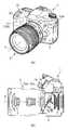
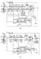
図1は本実施例における録音装置の構成を示すブロック図である。図2の(a)、(b)はそれぞれ、図1の録音装置を備えた撮像装置(カメラ)の斜視図及び断面図である。1は撮像装置、2は撮像装置1に装着されたレンズ、3は撮像装置1の筐体、4はレンズの光軸、5は撮影光学系、6は撮像素子をそれぞれ示す。また、30はレリーズ釦、31は操作釦である。撮像装置1には、第1のマイクロホン7a及び第2のマイクロホン7bが設けられている。32a、32bはそれぞれ、マイクロホン7a、7bのために筐体3に設けられた開口部である。開口部32bには音響抵抗体41が貼り付けられている。後述するように、音響抵抗体41は筐体3を偏肉構造にすることや、別途の部品により構成することも可能である。撮像装置1は、マイクロホン7a、7bを用いて、画像の取得と同時に音声を記録することができる。 FIG. 1 is a block diagram showing the configuration of a recording apparatus in this embodiment. 2A and 2B are a perspective view and a cross-sectional view, respectively, of an image pickup apparatus (camera) provided with the recording apparatus of FIG.
撮像装置1による動画の撮影動作について説明する。動画の撮影に先立って、不図示のライブビュー釦を押すことにより、撮像素子6の画像が撮像装置1に設けられた表示装置にリアルタイムに表示される。撮像装置1は動画撮影釦の操作と同期させて、撮像素子6より被写体の情報を設定されたフレームレートで得るとともに、マイクロホン7a,7bから音声情報を得て、これらを同期させて不図示のメモリへ記録を行う。動画撮影釦の操作と同期させて撮影を終了する。 A moving image shooting operation by the
図1を用いて、音声処理装置51の構成を説明する。52は可変高域通過フィルタ(HPF)である。53は残響抑圧器(reverberation suppressor)であり、ここには例えば残響抑圧適応フィルタが用いられる。54a,54bは、マイクロホンの出力信号をデジタル化する第1のA/Dコンバータ(ADC)、55は第1の遅延器(DL)、56a,56bはDC成分カット用のHPFである。
61は自動レベル補正部(ALC)である。ALC61において、62a,62bはレベル調整用の可変ゲイン、63はレベル調整器(level contoroller)である。
71は第1のマイクロホン7aの信号と第2のマイクロホンの7b信号を合成する合成器である。合成器71において、72は低域通過フィルタ(LPF)、73は可変HPF、74は可変ゲイン、75は加算器である。
81は風検出器(wind-detector)である。風検出器81において、82a,82bは帯域通過フィルタ(BPF)、83は差分器、84は第2のA/Dコンバータ(ADC)、85は第2の遅延器、86はレベル検出器である。
87は残響抑圧器53を制御するスイッチ、88は合成器71を制御するスイッチ、89はモード切替操作部である。The configuration of the
87 is a switch for controlling the
図1及び図2において、筐体3には、マイクロホン用の開口部32a、32bが設けられている。ここで、開口部32bには、装置外部から第2のマイクロホン7bへの空気の移動を遮断するように、第2のマイクロホン7bを覆う音響抵抗体41が設けられている。一方、開口部32aには、第1のマイクロホン7aが被写体音を忠実に取得できるように、そのような音響抵抗体は設けられていない。音響抵抗体41は筐体3に密着して設けられている。ここでいう空気の移動とは、風による空気の移動を想定している。例えば、多孔質PTFEのように風による空気の移動よりもゆっくりとした時間で空気の移動を許し、風は通さないような材質を音響抵抗体として用いることも可能である。 1 and 2, the
音声処理装置51は、第1のマイクロホン7aからの信号をHPF52で処理した後、ADC54aでアナログ/デジタル変換(A/D変換)を行う。さらにADC54aの出力は第1の遅延器55によって適当な量遅延される。一方、音声処理装置51は、第2のマイクロホン7bからの信号をADC54bでA/D変換した後、残響抑圧器53で残響の抑圧を行う。残響抑圧器53の動作及び第1の遅延器55における遅延の与え方などについては後述する。 The
第1の遅延器55及びADC54bの出力はそれぞれDC成分カット用のHPF56a,56bで処理される。HPF56a,56bはアナログ部のオフセット除去を目的としているため、DCから可聴域以下の成分を除去できるとよい。そのためHPF56a,56bのカットオフ周波数は例えば10Hz程度に設定される。 The outputs of the
HPF56a,56bの出力はALC61に入力され、それぞれ可変ゲイン62a,62bによってゲイン調整される。このとき可変ゲイン62a,62bのゲインは、2つの信号レベルが同一となるように連動して制御される。レベル調整器63は可変ゲイン62a,62bの出力を得て、飽和が発生せずダイナミックレンジを有効に活用できるように適当にレベル調整を行う。このときレベル調整器63は可変ゲイン62a,62bの出力のうち大きいほうが飽和しないようにレベルを調整する。 Outputs of the
可変ゲイン62a,62bの出力は合成器71に入力される。可変ゲイン62aの出力は、HPF73を通過させた後に加算器75へ送られる。一方、可変ゲイン62bの出力は、LPF72及び可変ゲイン74を介して加算器75へ送られる。加算器75で合成された出力が風雑音処理後の音声として出力される。 The outputs of the
第1のマイクロホン7aの出力及び残響抑圧器53の出力はそれぞれ、風検出器81のBPF82a,82bに入力される。BPF82a,82bは第2のマイクロホン7bにおいて被写体音を忠実に取得できる範囲を通過させることを目的としている。そのため通過帯域は例えば30Hz〜1kHz程度に設定される。ただし上限の周波数は音響抵抗体41の構造などによって設定値を変えることができる。詳細については第2のマイクロホン7bの周波数特性と共に後述する。 The output of the
BPF82aの出力は第2のADC84でA/D変換された後、第2の遅延器85に送られる。第2の遅延器85における遅延の与え方などについては残響抑圧器53の動作と共に後述する。 The output of the
差分器83で、第2の遅延器85の出力とBPF82bの出力との差が計算され、この結果がレベル検出器86に送られる。レベル検出器86の動作については後述する。レベル検出器86によって風の強さを判断して、スイッチ87を制御して残響抑圧器53へのフィードバックを切り替える。また、レベル検出器86の検出結果は、合成器71を制御するスイッチ88の制御にも用いられる。モード切替操作部89がユーザによってOFFに設定されている場合には、スイッチ88は、後述する風が無い場合の処理を常に選択するように動作する。一方、モード切替操作部89がユーザによってAutoに設定されている場合には、スイッチ88は、レベル検出器86によって判断される風の強さに応じて、HPF52、HPF73のカットオフ周波数及び可変ゲイン74を変更するように動作する。この処理の詳細は後述する。 The
音響抵抗体41の効果や望ましい特性や風雑音の低減について図1、図3及び図4を用いて説明する。図3はマイクロホンの周波数特性を模式的に示した図であり、横軸は周波数を、縦軸はゲインを示している。図3において、(a)は第1のマイクロホン7aの被写体音取得特性、(b)は第2のマイクロホン7bの被写体音取得特性を示す。(c)は第1のマイクロホン7aの風雑音取得特性を、(d)は第2のマイクロホン7bの風雑音取得特性を示す。(e)は合成器71の出力の被写体音取得特性を、(f)は合成器71の出力の風雑音取得特性を示す。また、第1のマイクロホン7aと第2のマイクロホン7bとの特性の違いを明確にするために、(b)及び(d)には第1のマイクロホン7aの特性を破線で示した。図3中のf0は音響抵抗体41による構造的なカットオフ周波数を示し、f1は図1に示した合成器71におけるLPF72,HPF73のカットオフ周波数を示している。 The effects, desirable characteristics, and reduction of wind noise of the
図3(a)に示すように、第1のマイクロホン7aの被写体音取得特性は可聴域においてフラットであることが望ましい。これにより被写体音を忠実に取得することが可能となる。図3(b)に示すように、第2のマイクロホン7bは音響抵抗体41が被写体からの空気の移動を遮断するように設けられているので、特性が異なる。音響抵抗体41によるカットオフ周波数よりも低い周波数では、比較的忠実に音声信号を通過させる。これは、空気の疎密波である音によって音響抵抗体41が加振され、それによって音響抵抗体41が装置内部の空気を同じように加振するためである。一方、音響抵抗体41によるカットオフ周波数よりも高い周波数では、音声信号を遮断する。これは、空気の疎密波である音によって音響抵抗体41が加振されるが、音響抵抗体41が振動するよりも早く疎密が反転するために移動できなくなる状態である。このように、音響抵抗体41は構造的なLPFとして作用する。構造的にカットされ始める周波数f0を音響抵抗体41のカットオフ周波数と呼ぶ。 As shown in FIG. 3A, the subject sound acquisition characteristic of the
風雑音のパワーは低域に集中することが知られている。例えば第1のマイクロホン7aでの風雑音のパワーは、図3(c)に示すように、1kHz程度から低周波に向かって持ち上がっていくような特性が得られることが多い。図3(c)のような形状にならない場合でも風雑音は低周波(500Hz以下)の成分が支配的である。図3(d)に示すように第2のマイクロホン7bは、風雑音による低周波成分の持ち上がりが少ない。第1のマイクロホン7aの近傍では乱流が発生するなどして大きな気圧差が生まれやすい。これに対して、第2のマイクロホン7bには音響抵抗体41が被写体からの空気の移動を遮断するように設けられているので、乱流等に起因する大きな気圧差が発生しない。これが、第2のマイクロホン7bの出力は風雑音による低周波成分の持ち上がりが少ない理由である。 It is known that the power of wind noise is concentrated in the low range. For example, the power of wind noise in the
これらの信号を、合成器71で処理することを考える。図1を用いて説明したように、第1のマイクロホン7aの信号はHPF73で処理される。これは図3(a)の91で示した部分及び図3(c)の93で示した部分を切り取ることに相当する。第2のマイクロホン7bの信号はLPF72で処理される。これは図3(b)の92で示した部分及び図3(d)の94で示した部分を切り取ることに相当する。加算器75を通ると結果として被写体音特性は図3(e)のようになり、風雑音特性は図3(f)のようになる。図3(e)及び図3(f)で91a,92a、93a、94aで示した部分はそれぞれ91,92、93、94で示した部分が支配的となっている箇所である。なお、「支配的」と述べたのは、LPF72,HPF73の特性によって必ずしも他方がゼロにはならないからである。図3(e)及び図3(f)から明らかなように、合成器71の出力の被写体音特性は可聴域でフラットであり、風雑音特性は音響抵抗体41を設けたマイクロホンの特性となっている。 Consider processing these signals by the
図4にマイクロホンの取り付け構造の例を示す。図4において、33a,33bはそれぞれ、第1のマイクロホン7a及び第2のマイクロホン7bの保持弾性体である。34は第2のマイクロホン7b及び音響抵抗体41を保持するスリーブである。 FIG. 4 shows an example of a microphone mounting structure. In FIG. 4, 33a and 33b are holding elastic bodies for the
図4(a)は、筐体3の外側に音響抵抗体41を貼付した例である。図4(a)の例では装置の組立後に音響抵抗体41を貼付すればよいので、組立性を向上させることができる。 FIG. 4A shows an example in which an
図4(b)は、筐体3の内側に音響抵抗体41を貼付した例である。図4(b)の例では音響抵抗体41が筐体3の外部に露出しないために美観の点で優れる。 FIG. 4B is an example in which an
図4(c)は、筐体3の一部が音響抵抗体41の機能を兼ねている例である。図4(c)の例では、音響抵抗体41となる筐体3の一部が、音波によって振動するほど薄くされている。図4(c)の例では部品を削減しつつ、筐体3に音響抵抗体41を貼付する必要がないので美観の点で優れる。ただし、図4(c)の例では筐体3と音響抵抗体41が一体であるため一般的に設計の自由度は下がる。(音響抵抗体41を形成する部分の厚みによって筐体3の強度が制限される可能性があり、これらの両立が難しくなる。) FIG. 4C is an example in which a part of the
図4(d)は、第2のマイクロホン7bと音響抵抗体41を剛性の十分高いスリーブ34で保持するようにした例である。スリーブ34は第2のマイクロホン7bで取得したい周波数の帯域よりも十分高い周波数に1次共振周波数があることが望ましい(図3におけるf0よりもスリーブ34の共振周波数が高いことを意味する。)。図4(d)の例では音響抵抗体41を高い剛性のスリーブ34に添付するため、取り付け部構造の不要共振の影響を受けることなく、通過帯域において(図3のf0よりも低い周波数において)望ましい音声信号を得ることができる。 FIG. 4D shows an example in which the
次に、図1及び図5を用いて残響抑圧器53について説明する。第2のマイクロホン7bは音響抵抗体41によって覆われた構造をとっているために、その閉空間内において残響が生じる場合がある。本実施例ではそのような残響を抑圧するために残響抑圧器53を設けている。 Next, the
残響抑圧器53の具体的構成を図5に示した。残響抑圧器53は適応フィルタで構成されている。この適応フィルタは、以下で具体的に説明するように、風雑音の大きさを表す差分器83の出力、すなわち、第1のマイクロホン7aの出力信号と第2のマイクロホン7bの出力信号との差が最小になるようフィルタ係数を推定学習する。これにより、第2のマイクロホン7bの出力信号のうちの、音響抵抗体41と第2のマイクロホン7bとの間の閉空間で発生する残響成分を抑圧する。このような適応フィルタを用いることで、ユーザによるカメラの把持状態の変化や温度変化に伴う残響発生状態の変化に対しても適切に処理を行うことが可能となる。 A specific configuration of the
残響抑圧の原理について簡単に説明する。被写体音をs、第1のマイクロホン7aの被写体音取得特性をg1、第2のマイクロホン7bの被写体音取得特性をg2、残響の影響をrとする。g1及びg2は図3に示した周波数空間での特性を逆フーリエ変換したものに等しい。第2のマイクロホン7bに残響がある環境下で得られる第1のマイクロホン7aの信号x1及び第2のマイクロホン7bの信号x2は(1)式のように与えられる。 The principle of dereverberation will be briefly described. The object sound is s, the object sound acquisition characteristic of the

ただし、(1)式において、*は畳み込みを示す演算子である。図3で説明したようにf0より低い周波数においては、第1のマイクロホン7aと第2のマイクロホン7bで同じような被写体音を取得できる。さらに図1に示したように、BPF82a,82bによって適当な帯域の成分のみを取り出す。すなわちBPFが通過させる帯域は、可聴範囲であって、図3においてf0より低い周波数ということになる。人間の聴覚特性上、50Hz以下の帯域に対しては極端に感度が下がる。詳細はA特性カーブなどを参照すればよい。このため、BPF82a,82bは、たとえば30Hz〜1kHzを通過させるように設計すればよい。BPF82a、82bをBPFとし、BPF通過後の信号をx1_BPF、x2_BPFとすると、次式が成り立つ。 However, in the formula (1), * is an operator indicating convolution. As described with reference to FIG. 3, at the frequency lower than f0, the same subject sound can be acquired by the
g1≠g2かつg1*BPF=g2*BPFは、f0より低い周波数においては、第1のマイクロホン7aと第2のマイクロホン7bで同じような被写体音を取得できることと等価である。(2)式から明らかなように、図1の差分器83の入力は残響の影響rが無い場合は、等しいものとなる。(2)式からx1_BPF=dを望みの応答、x2_BPF=uを入力として適応フィルタを動作させることで残響の影響を低減できる。 g1 ≠ g2 and g1 * BPF = g2 * BPF is equivalent to that the same subject sound can be acquired by the
残響抑圧器53のフィルタをhで表現すると、適応フィルタ出力yは次式のように与えられる。 When the filter of the
ただし、(3)式において、nはnサンプル目の信号であることを示し、Mは残響抑圧器53のフィルタ次数を、hの下添え文字はnサンプル目のフィルタhの値であることを示している。入力uはx2_BPFを用いればよい。 However, in the expression (3), n indicates the signal of the nth sample, M indicates the filter order of the
さらに、望みの応答はdはx1_BPFを用いればよいので、誤差信号eは次のように表現される。 Further, since the desired response may use x1_BPF for d, the error signal e is expressed as follows.
適応アルゴリズムとしては様々なものが提案されているが、ここでは一例としてLMSアルゴリズムでのhの更新式を次に示す。 Various adaptive algorithms have been proposed. Here, as an example, an updating formula of h in the LMS algorithm is shown below.
ただし、(5)式において、μはステップサイズパラメータである。以上によれば、適当な初期的なhを与えた後に、(5)式を用いてhを更新することでdに向かってuが近づいていく。すなわち、rの影響が低減されてx1_BPF=x2_BPFに近くなる。このときは|h*r|=1がBPFの通過帯域において成り立っている。ただし、風雑音が支配的な環境下においては(5)式の更新が正しく行われないので、スイッチ87によって適応フィルタの推定学習を停止させる。スイッチ87の制御シーケンスに関しては風検出器81の動作と共に後述する。 However, in the equation (5), μ is a step size parameter. According to the above, after giving an appropriate initial h, u is approached toward d by updating h using equation (5). In other words, the influence of r is reduced and approaches x1_BPF = x2_BPF. At this time, | h * r | = 1 holds in the BPF passband. However, since the update of equation (5) is not performed correctly in an environment where wind noise is dominant, the adaptive filter estimation learning is stopped by the
以上に説明したように、残響抑圧器53によって残響が抑圧される。一方で、図5から明らかなように残響抑圧器53では、その適応フィルタの次数に応じて信号が遅延する。これらを補うために、図1においては第1の遅延器55及び第2の遅延器85を備えている。代表的には残響抑圧器53のフィルタ次数の半分(=M/2)の遅延を与えておけばよい(Mが奇数の場合は近傍の値でもよい。)。このときは例えばh(M/2)=1としてその他のhは全て0と初期化することで、残響が無い状態を初期値として適応アルゴリズムを動作させることができる。メモリ上に残響抑圧のための適当な初期値が保存されているときは、hをその値で初期化してから動作を開始してもよい。例えば、初期値を以下のように設定することが考えられる。フィルタ係数は、マイクロホン7a、7b周辺の寸法、構造部材の材質などの設計値に基づいて、ある程度は推定することができる。そこで、設計値から求めたフィルタ係数を初期値として設定してもよい。また、録音装置の電源がOFFにされた際のフィルタ係数をメモリ上に記憶しておき、それを録音装置の次回起動時の初期値として設定してもよい。また、録音装置の生産過程において、所定の基準音を発生させることでフィルタ係数を算出してメモリに記憶しておき、それを録音装置の起動時の初期値として設定してもよい。 As described above, the reverberation is suppressed by the
次に、ALC61の動作について説明する。ALCは音声信号の飽和を抑制しつつ、ダイナミックレンジを有効に活用するために設けられる。音声信号は時間軸に対するパワー変動が大きいので適当にレベルを調整する必要がある。ALC61に設けられたレベル調整器63は可変ゲイン62a,62bからの出力をモニタする。 Next, the operation of the
まず、アタック動作について説明する。レベルの大きい方の信号が予め定めたレベルを超えたと判断した時に、予め定めたステップだけゲインを下げる。この動作を予め定めた周期で繰り返す。この動作をアタック動作と呼ぶ。アタック動作により飽和を防ぐことが可能となる。 First, the attack operation will be described. When it is determined that the signal having the higher level exceeds a predetermined level, the gain is decreased by a predetermined step. This operation is repeated at a predetermined cycle. This operation is called an attack operation. Saturation can be prevented by the attack operation.
次にリカバリ動作について説明する。レベルの大きい方の信号が予め定めた時間予め定めたレベルを超えることがなかった時に、予め定めたステップだけゲインを上げる。この動作を予め定めた周期で繰り返す。この動作をリカバリ動作と呼ぶ。リカバリ動作により静かな環境での音を得ることが可能となる。 Next, the recovery operation will be described. When the signal having the higher level does not exceed a predetermined level for a predetermined time, the gain is increased by a predetermined step. This operation is repeated at a predetermined cycle. This operation is called a recovery operation. The sound in a quiet environment can be obtained by the recovery operation.
ALC61内にある可変ゲイン62a,62bは連動して動作している。すなわち可変ゲイン62aがアタック動作でゲインが下がるときには、同じ量だけ可変ゲイン62bのゲインも下がる。このような動作をすることで、信号チャンネル間のレベル差がなくなり、後の合成器71でチャンネル間の信号を混合した場合に違和感が少なくなる。 The
次に、風検出器81について説明する。第1のマイクロホン7aで収音される風雑音をw1、第2のマイクロホン7bで収音される風雑音をw2とする。図3で説明したように風雑音のパワーは低域に集中しているのでBPF82a,82bによって遮断されることが無い。このため差分器83の出力として、w1−w2が得られる。なお、前述した残響の影響は無視できると仮定している。実環境においても、残響の影響は風雑音に比べると十分に小さく無視できるレベルである。 Next, the
レベル検出器86では差分器83の出力を絶対値演算した後に適当にLPF処理する。LPFのカットオフ周波数は風検出器の安定性と検出速度によって決定すればよいが0.5Hz程度であればよい。LPFは遮断帯域の信号を積分し、通過帯の信号はそのまま通すような動作をするので、結果として積分動作+HPFと同じような効果が得られる。そのため、絶対値演算が一定時間(これは前述のカットオフ周波数によって変化する)に亘って高いレベルを維持すると大きな出力となる。つまり適当な時間に亘って、Σ|w1−w2|をモニタしていることと等価である。 The
図6に風の強さの違いによる風検出器81の出力信号の例を示した。図6(a),(b),(c)は第1のマイクロホン7a及び第2のマイクロホン7bで得られる信号を示した図であり、横軸は時間を縦軸は信号レベルを示している。図6(a),(b),(c)において信号レベルの+1はプラス方向の信号が飽和するレベルを示している。また図6(a)は風が無い状態、図6(b)は風が弱い状態、図6(c)は風が強い状態の信号をそれぞれ示している。風の強さに応じて第1のマイクロホン7aの信号レベルが大きくなっており、風雑音が発生していることが分かる。一方で、第2のマイクロホン7bの信号レベルは第1のマイクロホン7aの信号レベルに比べて余り上昇していないことが分かる。音響抵抗体41の効果によって風雑音が低減されていることを示している。 FIG. 6 shows an example of the output signal of the
このとき前述した風検出器81の処理を施した結果を図6(d)に示した。図6(d)の横軸は図6(a),(b),(c)と同じ時間を、縦軸は風検出器の出力を示している。なお、BPF82a,82bは30Hz〜1kHzを通過帯域、レベル検出器86内のLPFのカットオフ周波数は0.5Hzとした。風検出器81の出力が風のないときはほぼゼロ付近で推移しており、風の強さに応じて値が大きくなることが分かる。また図6(d)において、0秒付近の信号が小さいのはレベル検出器86内のLPFの影響で立ち上がりが遅れるためである。風を検出するまでに図6(d)の信号の立ち上がりに示す程度の遅れが発生する。遅れを小さくすると風の揺らぎの影響を受けやすくなるという問題もあるので、本実施例では、図6に示す程度の遅れで風を検出することにした。 FIG. 6D shows the result of applying the processing of the
風検出器81の出力は、前述の残響抑圧器53のスイッチ87に用いられるほか、後述するHPF52の切替、及び合成器71内の合成処理の切替に用いられる。 The output of the
次に、合成器71の動作について図1及び図7を用いて説明する。図1において、風検出器81の出力に基づいて、HPF73のカットオフ周波数及び可変ゲイン74を変更することを説明したが、具体的な変更方法について図7を用いて説明する。 Next, the operation of the
図7(a)及び図7(c)はそれぞれ、合成器71の構成例を示している。図7(b)及び図7(d)はそれぞれ、図7(a)及び図7(c)の可変部の変更方法を示す図である。 FIG. 7A and FIG. 7C each show a configuration example of the
まず、図7(a)の構成について説明する。図7(a)に示した合成器71は、図1に示したものと同一の構成である。図7(a)においてLPF72のカットオフ周波数は固定されており、例えば1kHzである。図7(b)において上段は可変ゲイン74のゲインを、下段はHPF73のカットオフ周波数をそれぞれ模式的に示している。また、図7(b)の横軸は2つのグラフにおいて共通であり、Wn1,Wn2,Wn3は風雑音の大きさを示す値でこの順に風雑音が強いことを示している。 First, the configuration of FIG. 7A will be described. The
図7(b)に示すように風雑音が所定値Wn1より小さい場合は風処理が必要ないとして、可変ゲイン74のゲインは0、HPF73のカットオフ周波数は50Hzに設定される。結果として図7(a)に示す回路を通すことで、第2のマイクロホン7bからの信号は完全に遮断され、可聴域(ここではHPF73のカットオフ周波数である50Hzより高い周波数が音の支配的成分になるとして可聴域としている。)の信号を第1のマイクロホン7aのみから得ることができる。これは音響抵抗体41を設けた第2のマイクロホン7bの信号を用いずに済むことから、忠実に被写体の音声を得られていると考えられる。 As shown in FIG. 7B, when the wind noise is smaller than the predetermined value Wn1, it is determined that wind processing is not necessary, and the gain of the
風雑音がWn1のレベルを超えて、Wn1からWn2の間にある時を説明する。このとき、可変ゲイン74の値は次第に増加すると共に、HPF73のカットオフ周波数は次第に持ち上がる。前述の制御を行うことで、低周波の音声信号において次第に音響抵抗体41を設けた第2のマイクロホン7bからの信号の比率を高める。第1のマイクロホン7aからの信号には風雑音が大きく作用しているが、HPF73のカットオフ周波数を上げることで風雑音を低減させている。 The case where the wind noise exceeds the level of Wn1 and is between Wn1 and Wn2 will be described. At this time, the value of the
風雑音がWn2のレベルを超えて、Wn2からWn3の間にある時を説明する。このとき、可変ゲイン74の値は1に固定されるとともに、HPF73のカットオフ周波数は次第に持ち上がる。前述の制御を行うことで、LPF72のカットオフ周波数からHPF73のカットオフ周波数までの間に存在する音声は失われるが、風雑音をより低減することができる。過剰にHPF73のカットオフ周波数を上げると、被写体音の劣化が大きくなりすぎてしまうので、適当なカットオフ周波数以上には上げないようにしている。図6(b)の例では風雑音の大きさがWn3を超えた場合にはHPF73のカットオフ周波数は2kHzに固定されてこれ以上には変化しない。 The case when the wind noise exceeds the level of Wn2 and is between Wn2 and Wn3 will be described. At this time, the value of the
別の例である図7(c)の構成について説明する。図7(c)に示した合成器71は、固定のLPF72と可変ゲイン74に代えて、可変LPF76を設けたものである。図7(d)において、上段は可変LPF76のカットオフ周波数を、下段はHPF73のカットオフ周波数をそれぞれ模式的に示している。また、図7(d)の横軸は2つのグラフにおいて共通であり、Wn1,Wn2,Wn3は風雑音の大きさを示す値でこの順に風雑音が強いことを示している。 Another configuration of FIG. 7C will be described. The
図7(d)に示すように、風雑音が予め定めた値Wn1より小さい場合は風処理が必要ないとして、可変LPF76及びHPF73のカットオフ周波数は50Hzに設定される。結果として図7(c)に示す回路を通すことで、第2のマイクロホン7bからの信号はほぼ完全に遮断され、可聴域(ここではHPF73のカットオフ周波数である50Hzより高い周波数が音の支配的成分になるとして可聴域としている。)の信号を第1のマイクロホン7aのみから得ることができる。これは音響抵抗体41を設けた第2のマイクロホン7bの信号を用いずに済むことから、忠実に被写体の音声を得られていると考えられる。 As shown in FIG. 7D, if the wind noise is smaller than the predetermined value Wn1, the cut-off frequency of the
風雑音がWn1のレベルを超えて、Wn1からWn2の間にある時を説明する。このとき、可変LPF76及びHPF73のカットオフ周波数は一致したまま次第に持ち上がる。前述の制御を行うことで、低周波の音声信号は次第に音響抵抗体41を設けた第2のマイクロホン7bからの信号を用いることになる。第1のマイクロホン7aからの信号には風雑音が大きく作用しているが、HPF73のカットオフ周波数を上げることで風雑音を低減させている。 The case where the wind noise exceeds the level of Wn1 and is between Wn1 and Wn2 will be described. At this time, the cut-off frequencies of the
風雑音がWn2のレベルを超えて、Wn2からWn3の間にある時を説明する。このとき、可変LPF76のカットオフ周波数1kHzに固定されるとともに、HPF73のカットオフ周波数はさらに持ち上がる。前述の制御を行うことで、LPF72のカットオフ周波数からHPF73のカットオフ周波数までの間に存在する音声は失われるが、風雑音をより低減することができる。過剰にHPF73のカットオフ周波数を上げると、被写体音の劣化が大きくなりすぎてしまうので、適当なカットオフ周波数以上には上げないようにしている。図7(d)の例では風雑音の大きさがWn3を超えた場合にはHPF73のカットオフ周波数は2kHzに固定されてこれ以上には変化しない。 The case when the wind noise exceeds the level of Wn2 and is between Wn2 and Wn3 will be described. At this time, the cutoff frequency of the
以上の説明では、HPF73を可変ゲイン74及び可変LPF76の動作よりも広く動かす例について説明した。明らかにWn2=Wn3とすることで、HPF73の動作を可変ゲイン74及び可変LPF76と同様の範囲でのみ動作させることもできる。動作を制限すると風雑音の低減効果は小さくなるが、被写体音は忠実に取得できる。一方で、風が吹いた時に第1のマイクロホン7aに発生する風雑音の大きさはマイクロホンの取り付け構造などによって大きく異なる。Wn1,Wn2,Wn3の設定は、風雑音を低減する必要性と、被写体音を忠実に取得する必要性などを比較して調整すればよい。 In the above description, the example in which the
前述の説明では、図7に示した合成器71の例では、可変HPF、LPFのカットオフ周波数の変化させる範囲を具体的に示した。好ましい可変範囲やフィルタの構成について簡単に説明する。 In the above description, in the example of the
本実施例に示す合成器71においては、複数のマイクロホン7a,7bで取得された音声を合成する。このように帯域に分離して合成を行うような処理においては、特に複数のマイクロホンの信号が重なる周波数帯においてそれぞれの経路での位相が一致していることが望ましい。複数の経路における処理によって位相がずれた場合、波形が正しく重ならず相殺するような場合も発生するからである。これを十分に満たすためには、HPF73及びLPF72は同じ次数のFIRフィルタで構成されていると都合がよい。FIRフィルタを用いることで、いわゆる群遅延特性が得られ帯域ごとに処理した場合でも矛盾なく信号を合成することが可能となる。FIRフィルタで非常にカットオフ周波数が低い場合(正確にはサンプリング周波数との比率で規格化したときに非常に比率が小さくなる場合)において、十分なフィルタ性能を得るためには非常に高い次数のフィルタが必要となる。これは遮断/通過の対象となる周波数の波を得るために多くのサンプル数が必要となることから導かれる。フィルタの次数を無限に大きくすることはできないので、ここからカットオフ周波数の可変範囲の下限が決定される。図7(c)の構成においてはLPF,HPFを可変としているために、非常に低いカットオフ周波数とすると、可変LPF76及びHPF73の次数が非常に高くなってしまう。このため、周波数を下げる制限として、図7の例では可聴域の信号に大きな影響を与えない範囲として50Hzを例示した。前述の様に50Hzに限らず計算器資源によって適当に設定すればよい。図7(a)の例では、HPFのみ可変としているために、前述した高い次数のフィルタは1つで済む。計算量の削減という意味では、図7(c)の構成よりも勝っている。 In the
一方で、可変範囲の上限は音響抵抗体41を設けた第2のマイクロホン7bによって制限される。図3(b)に模式的に示したように、音響抵抗体41の影響によって第2のマイクロホン7bが取得できる被写体の帯域はf0までに制限されている。これを超えた部分では被写体音は得られていないので、図7の例における可変LPF76及びHPF73のカットオフ周波数はこれよりも低く設定されるべきである。図3におけるf1であり、明らかにf1<f0とすべきである。 On the other hand, the upper limit of the variable range is limited by the
図1、図3、図6、図8から図11を用いて、HPF52の効果、可変動作などについて説明する。図3及び図6を用いて説明したように、風雑音は低周波に集中すると共に、第1のマイクロホン7aと第2のマイクロホン7bでは影響の受け方が大きく異なる。すなわち弱い風であっても第1のマイクロホン7aには大きな風雑音が発生する。このことに伴う問題点として、ADC54aの飽和や、ALC61の動作が不適切になることが考えられる。ADC54aの飽和についての理解は容易なので説明を省略し、風雑音が発生しているときのALC61動作に伴う問題について述べる。 The effects, variable operations, and the like of the
HPF52が存在しない状態では、図6に示したように第1のマイクロホン7aに大きな風雑音が発生する。風雑音と被写体音が重畳されたときにおいても風雑音が支配的になることが想定される。このような環境下ではALC61は第1のマイクロホン7aの風雑音レベルを参照してレベル調整を行う。その後、合成器71内のHPF73で風雑音が処理されたときには音声信号のレベルが大きく低下してしまう。その結果、加算器75からの出力が非常に小さなものになってしまうという問題がある。つまり信号レベルが不適切な状態になってしまう。 When the
前述のADCの飽和や信号レベルが不適切になる問題を解決するために例えば、特許文献1に示した発明を適用することも考えられる。このときの音声処理装置51の例を図8に示した。図8において図1と同じ機能を持つものには同じ番号を付した。図8ではADC54a,54bの前に可変ゲイン62a,62bを備えておりADCの飽和を回避している。さらに、合成器71による風雑音処理後にもうひとつのALC61bを備えており、可変ゲイン62c及びレベル調整器63bによって風処理後の信号レベルが不適切になることを防いでいる。 In order to solve the above-described problems of ADC saturation and signal level becoming inappropriate, for example, it is conceivable to apply the invention shown in
しかしながら、図8の回路においても2つの問題点を抱えている。1つはレベルALC動作を2箇所で行うことによる回路規模の増大である。もうひとつは、合成器71の後方に配置されたALC61bでゲインが持ち上げられることによる量子化誤差の増大である。つまり、レベル調整器63aは風雑音を含んだ信号でレベル調整を行い、レベル調整器63bでは風雑音を含まない信号でレベル調整を行う。風雑音の低減効果が大きい場合は、レベル調整器63bで大きくゲインアップさせる必要が生じる。このとき、信号は既にデジタル化されているためにレベル調整に伴い、量子化誤差が増大してしまう。 However, the circuit of FIG. 8 also has two problems. One is an increase in circuit scale by performing level ALC operation at two locations. The other is an increase in quantization error due to the gain being raised by the
ここでいう量子化誤差について簡単に説明する。例えば、レベル調整器63bで12dBゲインを挙げる場合にはデジタル信号を2bit左にシフトする演算を行えばよいが、そのときに下位2bitに相当する情報がないので適当な値(例えば0)で埋める必要がある。この場合、下位2bitは常に0なので10進数で0の次は4しか表現できない。このように信号がとびとびにしか表現できず、自然の信号(連続)に対して量子化誤差が生じる。 The quantization error here will be briefly described. For example, when the 12 dB gain is increased by the
ここで図1に示したHPF52を考える。HPF52のカットオフ周波数を適当に設定することで風雑音の主要な成分を除去することができる。その結果、ADC54aの飽和を防ぐと共に、ALC61において適当なゲイン調整を行うことが可能となる。(ALC61の時点では風雑音に被写体音が埋もれないようになっているので、被写体音のレベルに合わせたALC動作を行うことが可能となる。) Consider the
HPF52におけるカットオフ周波数の制御シーケンスの例を図9を用いて説明する。図9(a)はスイッチ87の動作シーケンス、図9(b)はHPF52の動作シーケンス、図9(c)は可変ゲイン74の動作シーケンス、図9(d)はHPF73の動作シーケンスを示している。また、図9(a)から(d)において横軸は共通しており風雑音の大きさを示している。Wn1,Wn2,Wn3は風雑音の大きさを示す値でこの順に風雑音が強いことを示している。図9(c)、(d)の動作は図7(b)と同様であり説明を省略する。 An example of a cut-off frequency control sequence in the
風雑音が予め定めた値Wn1より小さい場合は風処理が必要ないとして、スイッチ87をON状態にして前述した残響抑圧器53の適応動作を行う。また、HPF52のカットオフ周波数は0Hz(=HPF動作せずにスルー)に設定される。音響抵抗体41を設けた第2のマイクロホン7bの信号を用いずに済むことから、忠実に被写体の音声を得られていると考えられる。 When the wind noise is smaller than the predetermined value Wn1, it is determined that wind processing is not necessary, and the
風雑音がWn1のレベルを超えると、風雑音の発生があるとして、スイッチ87をOFF状態にして前述した残響抑圧器53における適応フィルタの適応動作を停止させる。このような制御を行うことで不適切な適応動作を抑制することができる。 When the wind noise exceeds the level of Wn1, it is assumed that wind noise is generated, and the
Wn1からWn2の間にある時を説明する。このとき、HPF52のカットオフ周波数はHPF73のカットオフ周波数を超えない範囲で段階的に持ち上がる。前述の制御を行うことで、第1のマイクロホン7a発生した風雑音を低減することが可能となる。また、HPF73のカットオフ周波数を超えないように制御することで、HPF73出力に対してHPF52のカットオフ周波数は大きな影響を与えることがない。 The time between Wn1 and Wn2 will be described. At this time, the cutoff frequency of the
このことによる効果を説明する。HPF52は音声処理装置51のアナログ部(ADCより前段)に設けられることから、一般的にはIIRフィルタ(RC回路によるHPF)で構成されることになる。このときにHPF52は群遅延特性を満たすことができない。一方でIIRフィルタにおいても通過帯域においては位相の遅れは小さいので、群遅延特性を満たしていなくてもその位相遅れが影響を及ぼすことがない。前述したようにHPF52とHPF73のカットオフ周波数を制御することで、IIRフィルタによる位相遅れの影響を低減することができる。前述したように、帯域に分離して合成を行うような処理において、特に複数のマイクロホンの信号が重なる周波数帯においてそれぞれの経路での位相が一致していることが望ましい。しかしながら、これが守られない状況においてもその影響を低減できることを示している。また、前述したようにHPF52は音声処理装置51のアナログ部に設けられるが、アナログ回路において連続的にカットオフ周波数が変化するように構成すると、回路規模が大きくなってしまう。図9で説明したような制御シーケンスに適した回路にすることで、簡単な構成によって実現することができる。 The effect of this will be described. Since the
以上に説明した回路で処理をした信号の例を図10及び図11に示す。図10はHPF52を設けない場合を、図11はHPF52を設けた場合をそれぞれ示している。図10の信号は図1に対してHPF52の除いた状態で処理した信号である。また、図中に示したようにグラフは上から順に、ゲイン62a出力、ゲイン62b出力、HPF73出力、LPF72出力、加算器75出力をそれぞれ示している。また横軸は、時間を示しており、全てのグラフにおいて共通である。図10及び図11の例では2.5秒付近から被写体がしゃべっている状態(人の声が収音したい音である)を示している。また、図10及び図11で示した信号は風雑音のレベルが、図9のWn2のレベルにあるとして処理を行った。 Examples of signals processed by the circuit described above are shown in FIGS. FIG. 10 shows a case where the
2.5秒より以前の部分は図6に示したものと同じく、風雑音のみの状態である。この部分にのみ着目すると、図10と図11のゲイン62a出力は図11の方が大きいように見える。実際にはALC61によってゲインアップされているためである。これは被写体音と重なった2.5秒以降を見ると明らかである。 The part before 2.5 seconds is in the state of only wind noise, as shown in FIG. Focusing only on this part, the
2.5秒以降のゲイン62b出力に着目すると、図10の信号は、図11の信号に比べて明らかに信号レベルが低いことが分かる。これはALC61が第1のマイクロホン7aで発生した風雑音に対してレベル調整を行ったためにゲインが小さくなり、結果として被写体音が非常に小さく取得されている。一方で、図11の信号はHPF52の効果によって、第1のマイクロホン7aで発生した風雑音を低減させているので、ALC61のゲインが図10の状態に比べて高く保たれている。 Focusing on the output of the
図10のHPF73出力に着目すると、HPF73のカットオフ周波数を適当に処理することで風雑音は相当程度低減されていることが見て取れる。しかしながら、ゲイン62a出力の信号レベルに比べて、HPF73の信号レベルが大きく低下することから、最終的な加算器75の出力の信号レベルは非常に小さくなっていることが分かる。 Focusing on the output of the
一方、図11においても、HPF73のカットオフ周波数を適当に処理することで風雑音は相当程度低減されていることが見て取れる。さらに、LPF72の出力が大きく保たれているので、最終的な加算器75の出力の信号レベルも十分なレベルに保たれていることが分かる。 On the other hand, also in FIG. 11, it can be seen that the wind noise is considerably reduced by appropriately processing the cutoff frequency of the
このように、HPF52をADC及びALCよりもマイクロホンに近い側に配置することで、高品質な音声を得ることが可能となる。 In this way, by arranging the
本実施例の別の回路構成の例を図12に示す。図12(a)はALCをアナログ部に配置した例であり、図12(b)はALC61を合成器71の後方に配置した例である。このような構成でも本実施例に示した効果を得ることが可能となる。 An example of another circuit configuration of this embodiment is shown in FIG. FIG. 12A shows an example in which the ALC is arranged in the analog part, and FIG. 12B shows an example in which the
以上に説明したように、本発明によれば音響抵抗体で風雑音を低減しつつも残響音を抑制した高品位な音声を得ることが可能となる。 As described above, according to the present invention, it is possible to obtain high-quality sound in which reverberation is suppressed while reducing wind noise with an acoustic resistor.
(実施例2)
以下、図13から図14を参照して、本発明の第2の実施例による、録音装置及び録音装置を備えた撮像装置について説明する。第2の実施例において第1の実施例と同じ動作をするものについては同じ番号を付した。(Example 2)
A recording apparatus and an image pickup apparatus including the recording apparatus according to the second embodiment of the present invention will be described below with reference to FIGS. In the second embodiment, the same numbers are assigned to the same operations as those in the first embodiment.
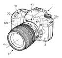
図13は撮像装置の斜視図である。図13は図2と類似するが、マイクロホン用の開口部32cが追加されている。開口部32cの奥には不図示のマイクロホン7cが設けられている。 FIG. 13 is a perspective view of the imaging apparatus. FIG. 13 is similar to FIG. 2, but an
図14は、図13に示した装置に対応する音声処理装置51の要部を説明する図である。図14は第1の実施例のうち、図12(a)に示した、ALCをアナログで行う回路を元に、ステレオに拡張を行っている。また、残響抑圧器53及びレベル検出器86は表記を簡略化/変更した。第1の実施例に対して、第1のマイクロホン7aが2つに拡張されている。ここでマイクロホン7aとマイクロホン7cはステレオの左右チャンネルを構成するマイクロホンでありその特性は等しくなるように設計されている。一方で、第2のマイクロホン7bには音響抵抗体41が設けられており、第1の実施例と同様の特性となっている。 FIG. 14 is a diagram for explaining a main part of the
図14で拡張された、HPF52b、ゲイン62c、ADC54c、DC成分カット用のHPF56c、HPF73bはそれぞれ実施例1に示した、HPF52、ゲイン62a、ADC54a、DC成分カット用のHPF56a、HPF73と同じ動きをする。ここでは動作が変化する遅延器55a,55b及び新設された位相比較器57、加算器58、ゲイン59について説明する。 The
ステレオ録音装置においては、音声信号の位相差により信号にステレオ感を与えている。一方、図13のような配置においては第1のマイクロホン7a、7cの間に第2のマイクロホン7bが配置されている。このような構成ではマイクロホン7aとマイクロホン7cの位相差を考えたときに、その中間に第2のマイクロホン7bの信号の位相が存在する。例えばマイクロホン7aとマイクロホン7b、マイクロホン7cとマイクロホン7bが等距離になるようにちょうど中間に第2のマイクロホン7bを配置したときには、位相もちょうど中間にある。そこで、図14の回路ではマイクロホン7aとマイクロホン7cの位相の差を計算して、それに対応した遅延を遅延器55a,55bで与えるようにする。 In a stereo recording device, a stereo feeling is given to a signal by a phase difference of an audio signal. On the other hand, in the arrangement as shown in FIG. 13, the
例えば、マイクロホン7aの信号よりもマイクロホン7cの信号が遅延している場合を考える。このとき後述するように、残響抑圧器はその中間の信号にあうように調整される。マイクロホン7aの信号と混合するときには位相を進めて、マイクロホン7cの信号と混合するときには位相を遅らせて混合すればよい。第1の実施例では、残響抑圧器53のフィルタ次数の半分(=M/2)の遅延を与えておけばよいとしたが、55aではこれよりも小さな遅延を与え、55bではこれよりも大きな遅延を与えればよい。またその絶対値はマイクロホンの配置によって異なるが、例えば前述したように、第2のマイクロホン7bが第1のマイクロホン7a、7cの中間に位置しているときには、位相比較器57で計算された位相差のそれぞれ半分をずらすようにすればよい。前述の処理を行うことで、ステレオ感を損なうことなく音声信号を得ることができる。 For example, consider a case where the signal of the
加算器58及びゲイン59について説明する。加算器28はマイクロホン7a及びマイクロホン7cの信号を加算する。ゲイン59は加算器58の出力を半分にする。その結果ゲイン59の出力はマイクロホン7aとマイクロホン7cの加算平均となる。その結果取得された音声の位相は、マイクロホン7aとマイクロホン7c信号の中間の位相になる。一方、BPF82aは実施例1で示したように30Hz〜1kHz程度の帯域しか通過させない。さらに音声処理装置51はさらにBPFの通過帯域に対して高い周波数の音声まで取得することが可能な構成となっている。このとき取得可能な音声信号において、マイクロホン7aとマイクロホン7c信号の間で位相の反転が起きないように配置されている。以上のことから、BPF82aで通過させる帯域に限って観察すると、マイクロホン7aとマイクロホン7c信号の間に存在する位相の差は小さい。このことから82a通過帯域における信号のレベルはほぼ加算されていると考えてよい。このためゲイン59で出力を半分にすることで信号のレベルは7a,7cとほぼ同一で、位相はその中間にあるような信号を得ることができる。本実施例では前述のゲイン59の出力にあわせるように残響抑圧器53を動作させる。 The
以上の構成によって、ステレオで録音する装置においても、ステレオ感を損なうことなく、本発明を容易に適用することができる。 With the above configuration, the present invention can be easily applied to a device for recording in stereo without impairing the stereo feeling.
本実施例においてはステレオの場合(高周波域まで取得する第1のマイクロホンが2個の場合)について説明したが、さらに多くのマイクロホンをもつ録音装置についても容易に拡張を行うことができる。 In the present embodiment, the case of stereo (a case where two first microphones are acquired up to a high frequency range) has been described. However, a recording apparatus having more microphones can be easily expanded.
(実施例3)
以下、図15を参照して、本発明の第3の実施例による、録音装置及び録音装置を備えた撮像装置について説明する。第3の実施例において第1の実施例と同じ動作をするものについては同じ番号を付した。(Example 3)
Hereinafter, with reference to FIG. 15, a recording apparatus and an image pickup apparatus including the recording apparatus according to a third embodiment of the present invention will be described. In the third embodiment, the same numbers are assigned to the same operations as those in the first embodiment.
第3の実施例による録音装置を備えた撮像装置の斜視図は第1の実施例の図2と同様のため省略する。図15は第3の実施例における音声処理装置51の要部を説明する図である。図15では、LPF72の前段に音声信号のサンプリング周波数を変更するアップサンプラ96が配されている。また、第1の実施例と異なり、ADC54a及び54bにおけるサンプリング周波数には異なる値が設定されている。ADC54aのサンプリング周波数に対し、ADC54bのサンプリング周波数は低い値に設定されている。また、ADC84のサンプリング周波数はADC54bと同じ値に設定されている。 The perspective view of the image pickup apparatus provided with the recording apparatus according to the third embodiment is the same as that of the first embodiment shown in FIG. FIG. 15 is a diagram for explaining a main part of the
ADC54b、ADC84、残響抑圧器53、及び新設されたアップサンプラ96について説明する。 The
第1のマイクロホン7aの出力は分岐して風検出器81に送られ、BPF82aを通過した後、ADC84でADC54aよりも低いサンプリング周波数でA/D変換される。このサンプリング周波数はBPF82aで通過した帯域を再現できる範囲の値であり、ADC54aのサンプリング周波数の整数分の1が望ましい。例えばBPF82aの通過帯域が30Hz〜1kHzであり、ADC54aのサンプリング周波数が48kHzである場合、48kHzの16分の1である3kHzに設定する。そして、ADC84の出力は遅延器85で遅延がされ差分器83に送られる。 The output of the
一方、第2のマイクロホン7bの信号はADC54bにおいてADC84と同様のサンプリング周波数にA/D変換される。そして、残響抑圧器53で残響が抑圧された後、分岐して風検出器81に送られ、BPF82bを通過した後、差分器83に送られる。残響抑圧器53のフィルタ次数MはADC54bでサンプリング周波数が16分の1に抑えられているので、従来の16分の1にしても従来と同等の効果を得ることができ、回路規模、演算量の減少に繋がる。残響抑圧器53のフィルタ次数Mの減少に伴い、遅延器85の遅延量も減少する。差分器83以下の動作は第1の実施例と同様であるため省略する。 On the other hand, the signal of the
分岐した残響抑圧器53の出力の一方はHPF56bを通過し、ALC61でゲイン調整されアップサンプラ96に送られる。アップサンプラ96では、可変ゲイン62bの出力をADC54aと同じサンプリング周波数に変換され、LPF72に送られる。アップサンプリングを行うとエリアシングを発生させることもあるが、LPF72によって高周波成分が低減され、エリアシングは除去される。 One of the branched outputs of the
第1のマイクロホン7aの後段のHPF52以下及び、LPF72以下の動作については第1の実施例と同様であるため省略する。 Since the operations after the
以上の構成によって、低周波成分をダウンサンプリングして残響抑圧処理を行うことで回路規模、演算量の低減が行うことができる。さらに、残響抑圧処理後にアップサンプリングを行うことで、高品位な音声を得ることが可能となる。 With the above configuration, it is possible to reduce the circuit scale and the amount of calculation by down-sampling the low frequency component and performing the dereverberation processing. Furthermore, high-quality sound can be obtained by performing upsampling after the dereverberation processing.
(実施例4)
以下、図16、図17を参照して、本発明の第4の実施例による、録音装置及び録音装置を備えた撮像装置について説明する。第4の実施例において第1の実施例と同じ動作をするものについては同じ番号を付した。Example 4
Hereinafter, with reference to FIGS. 16 and 17, a recording apparatus and an image pickup apparatus including the recording apparatus according to a fourth embodiment of the present invention will be described. In the fourth embodiment, the same numbers are assigned to the same operations as those in the first embodiment.
第4の実施例による録音装置を備えた撮像装置の斜視図は第1の実施例の図2と同様のため省略する。図16は第3の実施例における音声処理装置51の要部を説明する図である。図16の97は、BPF82b及び遅延器85の分岐した出力を受け、2つの信号の相互相関値を算出し、音源の到来方向が複数あるか否かを判定する相互相関算出器である。相互相関算出器97の動作については後述する。図17は被写体音の発生音源とマイクロホン7a,bの位置関係と、音声の伝播を模式的に表したものであり、図17(a)は被写体音が一方向から伝播する場合であり、図17(b)は被写体音が二方向から伝播する場合の模式図である。 The perspective view of the image pickup apparatus provided with the recording apparatus according to the fourth embodiment is the same as that of the first embodiment shown in FIG. FIG. 16 is a diagram for explaining a main part of the
図17を使って被写体音が二方向から伝播する場合の問題点について説明する。ある被写体O1から発せられる被写体音をs1、被写体O1とは異なる方向から発せられる被写体音をs2とする。そして、被写体O1からマイクロホン7aへ伝播する音声の伝達関数をT1aとしマイクロホン7bへ伝播する音声の伝達関数をT1bとする。また、同様に被写体O2からマイクロホン7a、7bに伝播する音声の伝達関数をそれぞれT2a、T2bとする。図17(a)のように被写体音の音源が一方向である場合、マイクロホン7a及び7bで取得される音声の信号x1及びx2はそれぞれ次式で表される。 A problem in the case where the subject sound propagates from two directions will be described with reference to FIG. A subject sound emitted from a certain subject O1 is represented by s1, and a subject sound emitted from a direction different from the subject O1 is represented by s2. The transfer function of the sound propagating from the subject O1 to the
マイクロホン7aの信号x1とマイクロホン7bの信号x2の間には、被写体音からのマイクロホン7a及びマイクロホン7bと距離の差により遅延が生じるが、時間的にズレがあるだけで2つの信号の相関は非常に高い。一方、図17(b)のように被写体音が二方向から伝播する場合、マイクロホン7a及び7bで取得される音声の信号x1及びx2はそれぞれ次式で表される。 There is a delay between the signal x1 of the
マイクロホン7aの信号x1とマイクロホン7bの信号x2の間には、2つのマイクロホン7a、7bと2つの被写体O1、O2の距離により、それぞれの遅延が生じる。2つの被写体O1、O2の位置が離れるに従い、T1aとT1b及びT2aとT2bでの遅延量にずれが生じるため、二つの信号の相関性が低くなる。その結果、残響抑圧器53の更新が正しく行われなくなる問題が発生する。 A delay occurs between the signal x1 of the
そこで第4の実施例による録音装置を備えた撮像装置では、相互相関算出器97を設け、2つの信号の相互相関値が規定値より低い場合は残響抑圧器の学習を止めることで上記の課題を解決する。 Therefore, in the imaging apparatus equipped with the recording apparatus according to the fourth embodiment, the
相互相関算出器97の動作について説明する。相互相関算出器97にはBPF82b及び遅延器85の分岐した出力が送られる。これはマイクロホン7a及びマイクロホン7bのBPF82a、BPF82aそれぞれを通過した30Hz〜1kHzの周波数帯域の音声信号である。この信号をそれぞれx1_BPF、x2_BPFとし、相互相関算出器97では、次のように2つの信号の相互相関値を算出する。データ長がNの時のnサンプル目における2つの信号の相互相関値R(n)は次式で求められる。 The operation of the
さらにこれをx1_BPFで正規化すると次式のように表される。
被写体音の方向が一方向である場合は、理想的にRnorm(n)は最大値に1を有する。しかし、被写体音の発生音源方向が二方向以上である場合は、2つの信号の相互相関が低くなるため、Rnorm(n)が1より低くなる。よって、求められた正規化相互相関値Rnorm(n)が予め定められた値Rn1よりも低い場合は、被写体音の発生音源方向が二方向以上であると判断し、スイッチ87をOFF状態にして残響抑圧器53の適応動作を停止させる。 When the direction of the subject sound is one direction, Rnorm (n) ideally has a maximum value of 1. However, when the sound source direction of the subject sound is two or more, Rnorm (n) is lower than 1 because the cross-correlation between the two signals is low. Therefore, if the obtained normalized cross-correlation value Rnorm (n) is lower than the predetermined value Rn1, it is determined that the sound source direction of the subject sound is two or more, and the
また、第3の実施例による撮像装置でも第1の実施例と同様にレベル検出器86の検出結果によってスイッチ87は切替えられる。つまり、相互相関算出器97で相互相関値がRn1よりも低いと検出されるか、又はレベル検出器86で風雑音がWn1のレベルを超えたことが検出されると、スイッチ87をOFF状態にして残響抑圧器53における適応フィルタの適応動作を停止させる。 In the imaging apparatus according to the third embodiment, the
このような制御を行うことで、被写体音が二方向以上の方向から伝播する場合でも適切な適応動作を行うことができ、高品位な音声を得ることが可能となる。 By performing such control, an appropriate adaptive operation can be performed even when the subject sound propagates from two or more directions, and high-quality sound can be obtained.
(他の実施形態)
また、本発明は、以下の処理を実行することによっても実現される。即ち、上述した実施形態の機能を実現するソフトウェア(プログラム)を、ネットワーク又は各種記憶媒体を介してシステム或いは装置に供給し、そのシステム或いは装置のコンピュータ(又はCPUやMPU等)がプログラムを読み出して実行する処理である。この場合、そのプログラム、及び該プログラムを記憶した記憶媒体は本発明を構成することになる。(Other embodiments)
The present invention can also be realized by executing the following processing. That is, software (program) that realizes the functions of the above-described embodiments is supplied to a system or apparatus via a network or various storage media, and a computer (or CPU, MPU, etc.) of the system or apparatus reads the program. It is a process to be executed. In this case, the program and the storage medium storing the program constitute the present invention.
Claims (11)
Translated fromJapanese前記音声処理装置の外部から前記第2の集音手段への空気の移動を低減するために、前記第2の集音手段を覆うように設けられ、前記第2の集音手段の出力信号における第1の周波数よりも高い周波数を減衰させる低減手段と、
前記第1の集音手段の出力信号を処理するハイパスフィルタと、
前記第2の集音手段の出力信号を処理するローパスフィルタと、
前記ハイパスフィルタの出力信号と前記ローパスフィルタの出力信号とを加算して出力する加算手段と、
前記第2の集音手段と前記ローパスフィルタとの間に設けられ、前記第2の集音手段の出力信号を処理する適応フィルタと、
前記第1の集音手段の出力信号から前記第1の周波数よりも低い周波数の信号を取り出す第1のフィルタと、
前記適応フィルタの出力信号から前記第1の周波数よりも低い周波数の信号を取り出す第2のフィルタとを有し、
前記適応フィルタは、前記第1のフィルタの出力と前記第2のフィルタの出力との差が最小になるように前記第2の集音手段の出力信号を処理することを特徴とする音声処理装置。An audio processing apparatus having a first sound collecting means and a second sound collecting means,
In order to reduce the movement of air from the outside of the sound processing device to the second sound collecting means, the second sound collecting means is provided so as to coverthe output signal of the second sound collecting means. Reducing meansfor attenuating frequencies higher than the first frequency ;
A high pass filter for processing the output signalof the first sound collecting means;
A low-pass filter for processing an output signalof the second sound collecting means;
Adding means for adding and outputting the output signal of thehigh-pass filter and the output signal of thelow-pass filter ;
Provided between thelow-pass filter and the second sound collectingmeans, anadaptive filter for processing an output signal of theprevious SL second sound collecting means,
A first filter for extracting a signal having a frequency lower than the first frequency from the output signal of the first sound collecting means;
A second filter for extracting a signal having a frequency lower than the first frequency from the output signal of the adaptive filter;
The adaptive filter processes the output signal of the second sound collecting means so that the difference between the output of the first filter and the output of the second filter is minimized. .
前記遅延手段の遅延量は前記適応フィルタの次数に応じて決定されることを特徴とする請求項2に記載の音声処理装置。Delay means for delaying the output signal of the first sound collecting means;
The speech processing apparatus according to claim 2, wherein the delay amount of the delay means is determined according to the order of the adaptive filter.
前記適応フィルタよりも前段において、前記第1の変換手段のサンプリング周波数よりも低いサンプリング周波数で前記第2の集音手段のアナログ出力信号をデジタル信号に変換する第2の変換手段と、
前記第2の変換手段でデジタル信号に変換され前記適応フィルタを通過した前記第2の集音手段の出力信号のサンプリング周波数を、前記第1の変換手段のサンプリング周波数と同じサンプリング周波数に変更するアップサンプラと、
を更に有する特徴とする請求項1から3のいずれか1項に記載の音声処理装置。First conversion means for converting an analog output signal of the first sound collection means into a digital signal;
A second conversion means for converting an analog output signal of the second sound collection means into a digital signal at a sampling frequency lower than the sampling frequency of the first conversion means, in a stage prior to the adaptive filter;
The sampling frequency of the output signal of the second sound collecting means that has been converted into a digital signal by the second converting means and passed through the adaptive filter is changed to the same sampling frequency as the sampling frequency of the first converting means. With sampler,
Speech processing apparatus according to any one of claims1 to3, wherein further comprising a.
前記判定手段により音源の到来方向が複数あると判定されたときは、前記適応フィルタの適応動作を停止するよう前記適応フィルタを制御する制御手段と、
を更に有することを特徴とする請求項1に記載の音声処理装置。A cross-correlation value between the output signal of the first sound collecting means and the output signal of the second sound collecting means is calculated, and it is determined whether there are a plurality of sound source arrival directions based on the calculated cross-correlation value. A determination means;
Control means for controlling the adaptive filter to stop the adaptive operation of the adaptive filter when the determination means determines that there are a plurality of sound source arrival directions;
The speech processing apparatus according to claim1 , further comprising:
ハイパスフィルタが、前記第1の集音手段の出力信号を処理するステップと、
ローパスフィルタが、前記第2の集音手段の出力信号を処理するステップと、
加算手段が、前記ハイパスフィルタの出力信号と前記ローパスフィルタの出力信号とを加算して出力する加算ステップと、
適応フィルタが、前記第2の集音手段の出力信号を処理する処理ステップと、
第1のフィルタが、前記第1の集音手段の出力信号から前記第1の周波数よりも低い周波数の信号を取り出すステップと、
第2のフィルタが、前記適応フィルタの出力信号から前記第1の周波数よりも低い周波数の信号を取り出すステップとを有し、
前記処理ステップでは、前記適応フィルタが、前記第1のフィルタの出力と前記第2のフィルタの出力との差が最小になるように前記第2の集音手段の出力信号を処理することを特徴とする音声処理方法。A first sound collecting means, a second sound collecting means, and a second sound collecting means so as to cover the second sound collecting means in order to reduce air movement from the outside of the apparatus to the second sound collecting means; A voice processing method in a voice processing apparatus comprising:a reduction meansfor attenuating a frequency higher than the first frequency in the output signal of the second sound collection means ,
A high-pass filterprocessing the output signal of the first sound collecting means;
A low-pass filterprocessing the output signalof the second sound collecting means;
An adding step for adding andoutputtingthe output signal of thehigh-pass filter and the output signal of thelow-pass filter ;
A processing step in which an adaptive filter processes an output signal of the second sound collecting means;
A first filter extracting a signal having a frequency lower than the first frequency from an output signal of the first sound collecting means;
A second filter extracting a signal having a frequency lower than the first frequency from the output signal of the adaptive filter;
In the processing step, the adaptive filter processes the output signal of the second sound collecting means so that the difference between the output of the first filter and the output of the second filter is minimized. Voice processing method.
Priority Applications (3)
| Application Number | Priority Date | Filing Date | Title |
|---|---|---|---|
| JP2010277419AJP5728215B2 (en) | 2010-12-13 | 2010-12-13 | Audio processing apparatus and method, and imaging apparatus |
| US13/302,072US9082410B2 (en) | 2010-12-13 | 2011-11-22 | Audio processing apparatus, audio processing method, and image capturing apparatus |
| CN201110415369.5ACN102568492B (en) | 2010-12-13 | 2011-12-13 | Audio processing apparatus, audio processing method, and image capturing apparatus |
Applications Claiming Priority (1)
| Application Number | Priority Date | Filing Date | Title |
|---|---|---|---|
| JP2010277419AJP5728215B2 (en) | 2010-12-13 | 2010-12-13 | Audio processing apparatus and method, and imaging apparatus |
Publications (3)
| Publication Number | Publication Date |
|---|---|
| JP2012129652A JP2012129652A (en) | 2012-07-05 |
| JP2012129652A5 JP2012129652A5 (en) | 2014-01-30 |
| JP5728215B2true JP5728215B2 (en) | 2015-06-03 |
Family
ID=46199405
Family Applications (1)
| Application Number | Title | Priority Date | Filing Date |
|---|---|---|---|
| JP2010277419AExpired - Fee RelatedJP5728215B2 (en) | 2010-12-13 | 2010-12-13 | Audio processing apparatus and method, and imaging apparatus |
Country Status (3)
| Country | Link |
|---|---|
| US (1) | US9082410B2 (en) |
| JP (1) | JP5728215B2 (en) |
| CN (1) | CN102568492B (en) |
Families Citing this family (7)
| Publication number | Priority date | Publication date | Assignee | Title |
|---|---|---|---|---|
| JP6139835B2 (en)* | 2012-09-14 | 2017-05-31 | ローム株式会社 | Wind noise reduction circuit, audio signal processing circuit using the same, and electronic equipment |
| JP2015130547A (en)* | 2014-01-06 | 2015-07-16 | パナソニックIpマネジメント株式会社 | Recording device |
| US11043228B2 (en)* | 2015-05-12 | 2021-06-22 | Nec Corporation | Multi-microphone signal processing apparatus, method, and program for wind noise suppression |
| JP2017009663A (en) | 2015-06-17 | 2017-01-12 | ソニー株式会社 | Recorder, recording system and recording method |
| CN110858485B (en)* | 2018-08-23 | 2023-06-30 | 阿里巴巴集团控股有限公司 | Voice enhancement method, device, equipment and storage medium |
| JP6669219B2 (en)* | 2018-09-04 | 2020-03-18 | 沖電気工業株式会社 | Sound pickup device, program and method |
| US11955133B2 (en) | 2022-06-15 | 2024-04-09 | Analog Devices International Unlimited Company | Audio signal processing method and system for noise mitigation of a voice signal measured by an audio sensor in an ear canal of a user |
Family Cites Families (22)
| Publication number | Priority date | Publication date | Assignee | Title |
|---|---|---|---|---|
| JPH03106299A (en)* | 1989-09-20 | 1991-05-02 | Sanyo Electric Co Ltd | Microphone device |
| US5193117A (en)* | 1989-11-27 | 1993-03-09 | Matsushita Electric Industrial Co., Ltd. | Microphone apparatus |
| JPH03219798A (en)* | 1989-11-27 | 1991-09-27 | Matsushita Electric Ind Co Ltd | microphone device |
| JP3176474B2 (en)* | 1992-06-03 | 2001-06-18 | 沖電気工業株式会社 | Adaptive noise canceller device |
| JPH0965482A (en)* | 1995-08-25 | 1997-03-07 | Canon Inc | Sound collecting method and microphone device for implementing the method |
| JPH09218687A (en)* | 1996-02-14 | 1997-08-19 | Shinko Electric Co Ltd | Muffling device |
| US6496581B1 (en)* | 1997-09-11 | 2002-12-17 | Digisonix, Inc. | Coupled acoustic echo cancellation system |
| JP3882870B2 (en)* | 1998-05-14 | 2007-02-21 | ソニー株式会社 | Microphone |
| WO2003059010A1 (en)* | 2002-01-12 | 2003-07-17 | Oticon A/S | Wind noise insensitive hearing aid |
| US7330556B2 (en)* | 2003-04-03 | 2008-02-12 | Gn Resound A/S | Binaural signal enhancement system |
| CN1209889C (en) | 2003-04-21 | 2005-07-06 | 徐忠义 | Phoneme background noise inhibitor |
| DK200401280A (en)* | 2004-08-24 | 2006-02-25 | Oticon As | Low frequency phase matching for microphones |
| JP2006211302A (en) | 2005-01-28 | 2006-08-10 | Matsushita Electric Ind Co Ltd | Wind noise reduction body |
| JP2006262098A (en)* | 2005-03-17 | 2006-09-28 | Yamaha Corp | Howling canceller |
| US20060262938A1 (en)* | 2005-05-18 | 2006-11-23 | Gauger Daniel M Jr | Adapted audio response |
| JP4078368B2 (en) | 2005-09-14 | 2008-04-23 | キヤノン株式会社 | Silencer and image forming apparatus |
| EP2036396B1 (en)* | 2006-06-23 | 2009-12-02 | GN ReSound A/S | A hearing instrument with adaptive directional signal processing |
| JP2008060625A (en)* | 2006-08-29 | 2008-03-13 | Casio Comput Co Ltd | Stereo audio recording apparatus and microphone sensitivity difference correction method |
| WO2009078105A1 (en)* | 2007-12-19 | 2009-06-25 | Fujitsu Limited | Noise suppressing device, noise suppression controller, noise suppressing method, and noise suppressing program |
| CN201199709Y (en)* | 2008-05-28 | 2009-02-25 | 英华达(上海)电子有限公司 | Mobile communication terminal with function of removing noise |
| JP5063528B2 (en) | 2008-08-21 | 2012-10-31 | 株式会社オーディオテクニカ | Noise cancellation system |
| US8606572B2 (en)* | 2010-10-04 | 2013-12-10 | LI Creative Technologies, Inc. | Noise cancellation device for communications in high noise environments |
- 2010
- 2010-12-13JPJP2010277419Apatent/JP5728215B2/ennot_activeExpired - Fee Related
- 2011
- 2011-11-22USUS13/302,072patent/US9082410B2/ennot_activeExpired - Fee Related
- 2011-12-13CNCN201110415369.5Apatent/CN102568492B/ennot_activeExpired - Fee Related
Also Published As
| Publication number | Publication date |
|---|---|
| JP2012129652A (en) | 2012-07-05 |
| US9082410B2 (en) | 2015-07-14 |
| US20120148063A1 (en) | 2012-06-14 |
| CN102568492B (en) | 2014-06-25 |
| CN102568492A (en) | 2012-07-11 |
Similar Documents
| Publication | Publication Date | Title |
|---|---|---|
| JP5926490B2 (en) | Audio processing device | |
| JP5728215B2 (en) | Audio processing apparatus and method, and imaging apparatus | |
| TWI759652B (en) | Electrical network for processing acoustic signals, method for real-time acoustic processing and active noise cancellation audio device | |
| JP6351538B2 (en) | Multiband signal processor for digital acoustic signals. | |
| US8620388B2 (en) | Noise suppressing device, mobile phone, noise suppressing method, and recording medium | |
| JP4286637B2 (en) | Microphone device and playback device | |
| EP2209116A1 (en) | High range interpolation device and high range interpolation method | |
| JP2011509008A (en) | Noise suppression method and apparatus | |
| JP6637926B2 (en) | Voice processing device and control method thereof | |
| WO2019079948A1 (en) | Earphone and method for performing an adaptively self-tuning for an earphone | |
| WO2022227982A1 (en) | Tws earphone and playing method and device of tws earphone | |
| WO2012098856A1 (en) | Hearing aid and hearing aid control method | |
| WO2022259589A1 (en) | Ear-mounted device and reproduction method | |
| CN118474607A (en) | Active noise reduction method and device and active noise reduction earphone | |
| US20090220101A1 (en) | Method for the Active Reduction of Noise, and Device for Carrying Out Said Method | |
| WO2023214571A1 (en) | Beamforming method and beamforming system | |
| KR20250004929A (en) | Device for reducing noise during reproduction of audio signals using headphones or hearing aids, and corresponding method | |
| JP6929137B2 (en) | Speech processing device and its control method | |
| JP2010250131A (en) | Noise elimination device | |
| JP6985821B2 (en) | Speech processing device and its control method | |
| JP2004201033A (en) | Device and method for reducing noise | |
| JP6877246B2 (en) | Speech processing device and its control method | |
| JP6931296B2 (en) | Speech processing device and its control method | |
| JP6886352B2 (en) | Speech processing device and its control method | |
| JP2008022069A (en) | Voice recording apparatus and voice recording method |
Legal Events
| Date | Code | Title | Description |
|---|---|---|---|
| A521 | Request for written amendment filed | Free format text:JAPANESE INTERMEDIATE CODE: A523 Effective date:20131209 | |
| A621 | Written request for application examination | Free format text:JAPANESE INTERMEDIATE CODE: A621 Effective date:20131209 | |
| A977 | Report on retrieval | Free format text:JAPANESE INTERMEDIATE CODE: A971007 Effective date:20140620 | |
| A131 | Notification of reasons for refusal | Free format text:JAPANESE INTERMEDIATE CODE: A131 Effective date:20140630 | |
| A521 | Request for written amendment filed | Free format text:JAPANESE INTERMEDIATE CODE: A523 Effective date:20140828 | |
| TRDD | Decision of grant or rejection written | ||
| A01 | Written decision to grant a patent or to grant a registration (utility model) | Free format text:JAPANESE INTERMEDIATE CODE: A01 Effective date:20150306 | |
| A61 | First payment of annual fees (during grant procedure) | Free format text:JAPANESE INTERMEDIATE CODE: A61 Effective date:20150406 | |
| R151 | Written notification of patent or utility model registration | Ref document number:5728215 Country of ref document:JP Free format text:JAPANESE INTERMEDIATE CODE: R151 | |
| LAPS | Cancellation because of no payment of annual fees |