JP5725503B2 - Exterior member of saddle riding type vehicle - Google Patents
Exterior member of saddle riding type vehicleDownload PDFInfo
- Publication number
- JP5725503B2 JP5725503B2JP2011153052AJP2011153052AJP5725503B2JP 5725503 B2JP5725503 B2JP 5725503B2JP 2011153052 AJP2011153052 AJP 2011153052AJP 2011153052 AJP2011153052 AJP 2011153052AJP 5725503 B2JP5725503 B2JP 5725503B2
- Authority
- JP
- Japan
- Prior art keywords
- shroud
- fuel tank
- exterior member
- hook
- radiator
- Prior art date
- Legal status (The legal status is an assumption and is not a legal conclusion. Google has not performed a legal analysis and makes no representation as to the accuracy of the status listed.)
- Active
Links
Images


Classifications
- B—PERFORMING OPERATIONS; TRANSPORTING
- B62—LAND VEHICLES FOR TRAVELLING OTHERWISE THAN ON RAILS
- B62J—CYCLE SADDLES OR SEATS; AUXILIARY DEVICES OR ACCESSORIES SPECIALLY ADAPTED TO CYCLES AND NOT OTHERWISE PROVIDED FOR, e.g. ARTICLE CARRIERS OR CYCLE PROTECTORS
- B62J35/00—Fuel tanks specially adapted for motorcycles or engine-assisted cycles; Arrangements thereof
- B—PERFORMING OPERATIONS; TRANSPORTING
- B62—LAND VEHICLES FOR TRAVELLING OTHERWISE THAN ON RAILS
- B62J—CYCLE SADDLES OR SEATS; AUXILIARY DEVICES OR ACCESSORIES SPECIALLY ADAPTED TO CYCLES AND NOT OTHERWISE PROVIDED FOR, e.g. ARTICLE CARRIERS OR CYCLE PROTECTORS
- B62J23/00—Other protectors specially adapted for cycles
- B—PERFORMING OPERATIONS; TRANSPORTING
- B62—LAND VEHICLES FOR TRAVELLING OTHERWISE THAN ON RAILS
- B62K—CYCLES; CYCLE FRAMES; CYCLE STEERING DEVICES; RIDER-OPERATED TERMINAL CONTROLS SPECIALLY ADAPTED FOR CYCLES; CYCLE AXLE SUSPENSIONS; CYCLE SIDE-CARS, FORECARS, OR THE LIKE
- B62K11/00—Motorcycles, engine-assisted cycles or motor scooters with one or two wheels
- B62K11/02—Frames
- B62K11/04—Frames characterised by the engine being between front and rear wheels
- B—PERFORMING OPERATIONS; TRANSPORTING
- B60—VEHICLES IN GENERAL
- B60W—CONJOINT CONTROL OF VEHICLE SUB-UNITS OF DIFFERENT TYPE OR DIFFERENT FUNCTION; CONTROL SYSTEMS SPECIALLY ADAPTED FOR HYBRID VEHICLES; ROAD VEHICLE DRIVE CONTROL SYSTEMS FOR PURPOSES NOT RELATED TO THE CONTROL OF A PARTICULAR SUB-UNIT
- B60W2300/00—Indexing codes relating to the type of vehicle
- B60W2300/36—Cycles; Motorcycles; Scooters
Landscapes
- Engineering & Computer Science (AREA)
- Mechanical Engineering (AREA)
- Automatic Cycles, And Cycles In General (AREA)
Description
Translated fromJapanese本発明は、鞍乗り型車両の外装部材に関する。 The present invention relates to an exterior member of a saddle-ride type vehicle.
従来、鞍乗り型車両において、ラジエーターを側方から覆う外装部材であるラジエーターシュラウドを、燃料タンク、ラジエーター、及び、フレームから延ばした取り付けステーにボルトで固定するものが知られている(例えば、特許文献1参照)。 Conventionally, in a saddle-ride type vehicle, a radiator shroud, which is an exterior member that covers the radiator from the side, is fixed to a fuel tank, a radiator, and a mounting stay extended from the frame with bolts (for example, patents) Reference 1).
しかしながら、上記従来の鞍乗り型車両では、ラジエーターシュラウドを取付けるための専用の取り付けステーをフレームから延ばすため、フレームが重くなるとともに構造が複雑になるという課題がある。また、ラジエーターシュラウドと取り付けステーとの間は車幅方向に距離が離れているため、取り付けステーに当接するラジエーターシュラウドの締付け部を深くする必要があり、ラジエーターシュラウドの金型が複雑になるとともに、上記締付け部が大きくなることで外観に比較的大きな穴が存在することになり、意匠面における自由度の向上が望まれる。
本発明は、上述した事情に鑑みてなされたものであり、鞍乗り型車両の外装部材において、簡単な構造で、車両の外観に影響しないように、外装部材を固定できるようにすることを目的とする。However, in the conventional saddle-ride type vehicle, since a dedicated mounting stay for attaching the radiator shroud is extended from the frame, there is a problem that the frame becomes heavy and the structure becomes complicated. In addition, since the distance between the radiator shroud and the mounting stay is long in the vehicle width direction, it is necessary to deepen the tightening portion of the radiator shroud that abuts the mounting stay, and the mold of the radiator shroud becomes complicated, Since the tightening portion becomes large, a relatively large hole exists in the appearance, and improvement in the degree of freedom in the design surface is desired.
The present invention has been made in view of the above-described circumstances, and an object of the present invention is to enable an exterior member of a saddle-ride type vehicle to be fixed with a simple structure so as not to affect the appearance of the vehicle. And
上記目的を達成するため、本発明は、ヘッドパイプ(14)と、当該ヘッドパイプ(14)から後方に延びる左右一対のメインフレーム(15)と、外装部材(37)とを備えた鞍乗り型車両の外装部材において、前記外装部材(37)は、シュラウド(37)であり、その内側に、前記メインフレーム(15)に対して引っ掛け支持可能なフック部(75)を有し、当該フック部(75)を前記メインフレーム(15)に引っ掛けて支持することで、前記外装部材(37)が車両に係止され、前記シュラウド(37)は、ラジエーター(5)の側方を覆って上下に延びる前カバー部(60)と、当該前カバー部(60)の下部から燃料タンク(50)の後部まで延びる後カバー部(70)とを有し、前記後カバー部(70)は、前記前カバー部(60)の下部の後縁に連続して前記ラジエーター(5)の側板部(5C)を覆う中央部(71)と、当該中央部(71)の上部から後方へ延び、前記メインフレーム(15)及び前記燃料タンク(50)のタンク上部(52)の後部を覆う後部延在部(72)とを有し、前記後部延在部(72)の前部の上縁と前記前カバー部(60)の上部の下縁との間には開口(37A)が形成され、前記後部延在部(72)の後部には、前記燃料タンク(50)に締結される締付部(74)が設けられ、前記フック部(75)は、前記後部延在部(72)の前後の中間部に形成されることを特徴とする。
この構成によれば、ヘッドパイプと、ヘッドパイプから後方に延びるフレームと、外装部材とを備え、外装部材は、その内側に、フレームに対して引っ掛け支持可能なフック部を有し、フック部をフレームに引っ掛けて支持することで、外装部材が車両に係止されるため、フレームに専用のステー等を設けることなく、簡単な構造で外装部材を車両に固定できるとともに、フック部の部分では穴が必要ないため、車両の外観に影響しないように外装部材を固定できる。また、左右一対のメインフレームに外装部材が引っ掛けられて支持されるため、より強固に外装部材を支持できる。To achieve the above object, the present invention is a saddle riding typecomprising a head pipe (14), apair of left and right main frames (15) extending rearward from the head pipe (14), and an exterior member (37). In the exterior member of the vehicle, the exterior member (37) is ashroud (37), and has a hook portion (75) that can be hooked and supported on themain frame (15) on the inside thereof. (75) is hooked and supported on themain frame (15), so that the exterior member (37) is locked tothe vehicle, andthe shroud (37) covers the side of the radiator (5) and movesup and down. A front cover portion (60) that extends, and a rear cover portion (70) that extends from a lower portion of the front cover portion (60) to a rear portion of the fuel tank (50), wherein the rear cover portion (70) Hippopotamus A central portion (71) covering the side plate portion (5C) of the radiator (5) continuously to the rear edge of the lower portion of the portion (60), and extending rearward from the upper portion of the central portion (71), 15) and a rear extension part (72) covering the rear part of the tank upper part (52) of the fuel tank (50), the upper edge of the front part of the rear extension part (72) and the front cover part An opening (37A) is formed between the lower edge of the upper part of (60), and a fastening part (74) fastened to the fuel tank (50) is provided at the rear part of the rear extension part (72). It is provided, wherein the hook portion (75) is formed in the middle portion of the front and rear of the rear extending portion (72), characterized in Rukoto.
According to this configuration, the head pipe, the frame extending rearward from the head pipe, and the exterior member are provided, and the exterior member has the hook portion that can be hooked and supported on the frame on the inner side, and the hook portion is Since the exterior member is locked to the vehicle by being hooked and supported by the frame, the exterior member can be fixed to the vehicle with a simple structure without providing a dedicated stay or the like for the frame. Therefore, the exterior member can be fixed so as not to affect the appearance of the vehicle.Further, since the exterior member is hooked and supported by the pair of left and right main frames, the exterior member can be supported more firmly.
また、上記構成において、前記メインフレーム(15)間に前記燃料タンク(50)が配置され、当該燃料タンク(50)は、前記フック部(75)による引っ掛け支持部(80)の上方に配置される構成としても良い。
この場合、メインフレーム間に燃料タンクが配置され、燃料タンクは、フック部による引っ掛け支持部の上方に配置されるため、フック部を燃料タンクによって係止でき、フック部が外れることを防止できる。In the abovestructure, before Symbolsaid fuel tank (50) between the main frame (15) is arranged, the fuel tank (50) is arranged above the supporting portion hooked by the hook portion (75) (80) It is good also as a structure to be performed.
In this case, since the fuel tank is disposed between the main frames and the fuel tank is disposed above the hook support portion by the hook portion, the hook portion can be locked by the fuel tank, and the hook portion can be prevented from coming off.
さらに、前記燃料タンク(50)はその側面(52A)に凹部(57)を備え、前記フック部(75)は、前記メインフレーム(15)と前記凹部(57)との間に差し込まれて、前記メインフレーム(15)に沿ってスライドされる構成であっても良い。
この場合、フック部は、メインフレームと燃料タンクの側面の凹部との間に差し込まれて、メインフレームに沿ってスライドされるため、燃料タンクを車両に取り付けた状態で外装部材を着脱でき、メンテナンス性が良い。
また、前記燃料タンク(50)の前記凹部(57)は、前記シュラウド(37)が取り付けられた状態において、側面視で前記シュラウド(37)と重なる構成であっても良い。
この場合、燃料タンクの凹部は、シュラウドが取り付けられた状態において、側面視でシュラウドと重なり、凹部がシュラウドによって隠れて外側から視認されなくなるため、車両の外観に影響しないようにシュラウドを固定できる。Further, the fuel tank (50) includes a recess (57) on a side surface (52A) thereof, and the hook portion (75) is inserted between the main frame (15) and the recess (57), It may be configured to slide along the main frame (15).
In this case, since the hook portion is inserted between the main frame and the recess on the side surface of the fuel tank and is slid along the main frame, the exterior member can be attached and detached while the fuel tank is attached to the vehicle, and maintenance can be performed. Good sex.
Moreover, the said recessed part (57) of the said fuel tank (50) may be the structure which overlaps with the saidshroud (37) by the side view in the state in which the saidshroud (37) was attached.
In this case, the recess of the fuel tank, in a statewhere the shroud is attached,the shroud and overlap in side view, since the recess is no longer visible from the outside is hidden bythe shroud, can be fixedshroud so as not to affect the appearance of the vehicle.
また、前記シュラウド(37)は、前記メインフレーム(15)への前記引っ掛け支持部(80)の他に、複数箇所の締付部(63,64,74)で車両に締付支持され、前記引っ掛け支持部(80)は、前記複数の締付部(63,64,74)の略中央に配置される構成であっても良い。
この場合、シュラウドは、フレームへの引っ掛け支持部の他に、複数箇所の締付部で車両に締付支持され、引っ掛け支持部は、複数の締付部の略中央に配置され、引っ掛け支持部に大きな力が作用し難いため、シュラウドを強固に支持できる。
また、前記シュラウド(37)の車幅方向内側には前記ラジエーター(5)が設けられ、前記シュラウド(37)は、前記ラジエーター(5)及び前記燃料タンク(50)に締付支持される構成であっても良い。
この場合、シュラウドは、ラジエーター及び燃料タンクに締付支持されるため、シュラウドを支持するステー等を新たに設ける必要がなく、簡単な構造でシュラウドを固定できる。
Theshroud (37) is clamped and supported on the vehicle by a plurality of tightening portions (63, 64, 74) in addition to the hook support portion (80) to themain frame (15), The hook support portion (80) may be configured to be disposed at substantially the center of the plurality of tightening portions (63, 64, 74).
In this case, theshroud is clamped and supported by the vehicle at a plurality of tightening portions in addition to the hook supporting portion to the frame, and the hook supporting portion is disposed at substantially the center of the plurality of tightening portions. Therefore, theshroud can be firmly supported.
Moreover, said the vehicle width direction inner side of theshroud (37)said radiator (5) is provided, wherein theshroud (37), said radiator (5) and in fastening the support structure for a the fuel tank (50) There may be.
In this case,the shroud to be tightening supported radiator and fuel tank, there is no need to provide a stay or the like for supporting theshroud can be fixed tothe shroud with a simple structure.
本発明に係る鞍乗り型車両の外装部材では、外装部材は、その内側に、フレームに対して引っ掛け支持可能なフック部を有し、フック部をフレームに引っ掛けて支持することで、外装部材が車両に係止されるため、フレームに専用のステー等を設けることなく、簡単な構造で外装部材を車両に固定できるとともに、フック部の部分では穴が必要ないため、車両の外観に影響しないように外装部材を固定できる。
また、左右一対のメインフレームに外装部材が引っ掛けられて支持されるため、より強固に外装部材を支持できる。In the exterior member of the saddle-ride type vehicle according to the present invention, the exterior member has a hook portion that can be hooked and supported with respect to the frame on the inner side, and the hook portion is hooked and supported on the frame so that the exterior member is Since it is locked to the vehicle, it is possible to fix the exterior member to the vehicle with a simple structure without providing a dedicated stay etc. on the frame, and since there is no need for a hole in the hook part, it does not affect the appearance of the vehicle The exterior member can be fixed to.
Further, since the exterior member is hooked and supported by the pair of left and right main frames, the exterior member can be supported more firmly.
また、燃料タンクは、フック部による引っ掛け支持部の上方に配置されるため、フック部を燃料タンクによって係止でき、フック部が外れることを防止できる。
さらに、フック部は、メインフレームと燃料タンクの側面の凹部との間に差し込まれて、メインフレームに沿ってスライドされるため、燃料タンクを車両に取り付けた状態で外装部材を着脱でき、メンテナンス性が良い。
また、燃料タンクの凹部は、外装部材によって隠れて外側から視認されなくなるため、車両の外観に影響しないように外装部材を固定できる。Further, since the fuel tank is disposed above the hook support portion by the hook portion, the hook portion can be locked by the fuel tank, and the hook portion can be prevented from coming off.
Furthermore, since the hook portion is inserted between the main frame and the recess on the side surface of the fuel tank and is slid along the main frame, the exterior member can be attached and detached while the fuel tank is attached to the vehicle. Is good.
Further, since the recess of the fuel tank is hidden by the exterior member and is not visible from the outside, the exterior member can be fixed so as not to affect the appearance of the vehicle.
また、引っ掛け支持部は、複数の締付部の略中央に配置され、引っ掛け支持部に大きな力が作用し難いため、外装部材を強固に支持できる。
また、外装部材は、ラジエーター及び燃料タンクに締付支持されるため、外装部材を支持するステー等を新たに設ける必要がなく、簡単な構造で外装部材を固定できる。In addition, since the hook support portion is disposed substantially at the center of the plurality of tightening portions and a large force is unlikely to act on the hook support portion, the exterior member can be firmly supported.
Further, since the exterior member is clamped and supported by the radiator and the fuel tank, it is not necessary to newly provide a stay or the like for supporting the exterior member, and the exterior member can be fixed with a simple structure.
以下、本発明の実施の形態に係る自動二輪車について図面を参照して説明する。なお、以下の説明で、上下、前後、左右の方向は、車両の運転者から見た方向をいう。
図1は、本発明の実施の形態に係る自動二輪車の左側面図である。図2は、自動二輪車の前部を上方から見た平面図である。
自動二輪車1(鞍乗り型車両)は、車体フレーム10の前後の中央にエンジン11が配置され、前輪2を支持するフロントフォーク12が車体フレーム10の前端に操舵可能に支持され、後輪3を支持するスイングアーム13が車体フレーム10の後部の下部に設けられたオフロードタイプの鞍乗り型車両である。Hereinafter, a motorcycle according to an embodiment of the present invention will be described with reference to the drawings. In the following description, the up / down, front / rear, and left / right directions are directions viewed from the vehicle driver.
FIG. 1 is a left side view of a motorcycle according to an embodiment of the present invention. FIG. 2 is a plan view of the front portion of the motorcycle as viewed from above.
In the motorcycle 1 (saddle-ride type vehicle), an
車体フレーム10は、左右一対のフロントフォーク12を支持するヘッドパイプ14と、ヘッドパイプ14から後下方に延びる左右一対のメインフレーム15と、メインフレーム15の後端から後下方に延びた後、前下方へ湾曲して下方に延びる左右一対のピボットプレート16と、ヘッドパイプ14から下方に延び、エンジン11の前方で左右に分岐してエンジン11の下方を延び、ピボットプレート16の下端に連結されるダウンフレーム17と、ピボットプレート16の上部から後方へ略水平に延びる左右一対のシートレール18と、ピボットプレート16の上下の中間部とシートレール18の後部との間に渡される左右一対のリヤパイプ19とを備えて構成される。ダウンフレーム17とメインフレーム15とは、エンジン11の上方を延びる左右一対の補強パイプ9によって連結される。 The
ピボットプレート16には、左右のピボットプレート16を車幅方向に貫通するピボット軸20が設けられ、スイングアーム13は、ピボット軸20に揺動可能に軸支されている。後輪3は、スイングアーム13の後端に軸支される。ピボットプレート16の下部には、左右一対のステップ8が設けられている。
ヘッドパイプ14には、ステアリングシャフト(不図示)が軸支され、フロントフォーク12は、上記ステアリングシャフトの上端及び下端に連結されるトップブリッジ21及びボトムブリッジ22に連結される。操行ハンドル23(図2では不図示)はトップブリッジ21に取り付けられる。
燃料タンク50は、メインフレーム15に沿うようにヘッドパイプ14の上方に固定され、運転者が着座するシート25は、燃料タンク50の後部に連続し、シートレール18に支持されて後方に延びている。The
A steering shaft (not shown) is pivotally supported on the
The
エンジン11は、水冷の4サイクル式単気筒エンジンであり、車幅方向に延びるクランク軸(不図示)が収容されるクランクケース26と、クランクケース26の前部から僅かに前傾して上方に延びるシリンダ27とを備え、メインフレーム15とダウンフレーム17との間に支持されている。クランクケース26の後部には変速機28が一体的に設けられている。
シリンダ27 の前部には、排気管29が接続され、排気管29は右側方に屈曲して後方に延びて2又に分岐し、リヤパイプ19の下方に設けられる左右一対のマフラー30に接続される。The
An
シリンダ27の後方には、エンジン11に燃料及び空気を供給する吸気装置31が配置されている。吸気装置31の外気の取り込み口となるエアクリーナボックス32は、左右のシートレール18及びリヤパイプ19で囲まれた空間に配置され、エアクリーナボックス32の前部には、シリンダ27側へ延びるコネクティングチューブ33が接続される。
シリンダ27の前方には、上下に延びる板状のラジエーター5が設けられている。ラジエーター5はダウンフレーム17の左右に分割されて一対で設けられ、ダウンフレーム17に固定される。An
A plate-
自動二輪車1は、樹脂製の車体カバー35を有し、車体カバー35は、ヘッドパイプ14の前方を覆うフロントカバー36と、ダウンフレーム17の上部及びメインフレーム15の側方を覆う左右一対のシュラウド37(ラジエーターシュラウド)と、シート25の下方でエアクリーナボックス32及びマフラー30等を側方から覆う左右一対のサイドカバー38とを有している。
ボトムブリッジ22には、フロントフェンダー39が固定され、シート25の後方には、リヤフェンダ40が設けられている。The
A
図3は、自動二輪車1の右側面図であり、シュラウド37及びシート25を取り外した状態を示す図である。
左右のメインフレーム15は、直線状に後下方に延び、燃料タンク50は、左右のメインフレーム15間に跨って配置されている。燃料タンク50は、左右のメインフレーム15の間に挟まれるように配置されるタンク下部51と、左右のメインフレーム15の上方に位置するタンク上部52とを有している。燃料タンク50は樹脂製である。
タンク上部52の前部の上面には、給油口55に着脱自在なキャップ55Aが取り付けられている。タンク上部52の側面52Aには、シュラウド37を燃料タンク50に固定するボルト41,42(図4参照)が締結される前固定部53、及び、後固定部54が設けられている。前固定部53は給油口55の下方に位置し、後固定部54はタンク上部52の後部に位置している。FIG. 3 is a right side view of the
The left and right
A
タンク上部52の側面52Aの下縁部56は、メインフレーム15の上面15Aに沿って直線的に延びており、この下縁部56には、燃料タンク50の内面側に窪んだ凹部57が形成されている。凹部57は、燃料タンク50の前後の中間部に形成され、前固定部53と後固定部54との間に位置している。
燃料タンク50は、タンク上部52の前部に設けられたステー58、及び、不図示の複数の固定部を介して車体フレーム10に締結されている。A
The
ラジエーター5の上部には、冷却水の補充口を塞ぐラジエーターキャップ5Aが設けられている。また、ラジエーター5の上部の後面部には、ラジエーター5とエンジン11とを繋ぐ冷却水ホース5Bが接続されている。ラジエーター5の外側面部には、上下に延びる側板部5Cが設けられている。また、ラジエーター5の前面には、ラジエーター5に風を導くとともに前面をガードするラジエーターグリル4が設けられている。 A
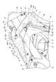
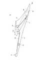
図4は、自動二輪車1の右側面図であり、シュラウド37の近傍を示す図である。図5は、右側のシュラウド37を側方から見た平面図である。図6は、右側のシュラウド37を上方から見た図である。左右の各シュラウド37は略左右対称に構成されているため、ここでは右側のシュラウド37について詳細に説明する。
シュラウド37は、前方から流れ込む走行風をラジエーター5に導入するための板状のカバーであり、図2及び図4〜図6に示すように、燃料タンク50の側面から前側へ斜め外側に張り出すように突出し、ラジエーター5の外側面を通ってラジエーター5よりも前方に延びている。FIG. 4 is a right side view of the
The
シュラウド37は、ラジエーター5の側方を覆って上下に延びる前カバー部60と、前カバー部60の下部から後方へ燃料タンク50の後部まで延びる後カバー部70とを有している。
前カバー部60は、タンク上部52の前固定部53から前下方に延びつつ車幅方向に広がるように前側に斜め外側へ延びる上部61と、上部61の下部から下方に延びてラジエーター5の側板部5Cを覆う下部62とを有している。上部61はメインフレーム15の上部及びラジエーター5の上部を覆ってラジエーター5の前方の頂点部60Aで下部62に合流する。この頂点部60Aはラジエーター5の前面よりも前方に張り出した部分である。下部62には、上下に延びるリブ82が形成されている。リブ82は、ラジエーター5の側板部5Cに当接し、シュラウド37をラジエーター5に係止する。
上部61の上端部には、ボルト41(図4)によってタンク上部52の前固定部53に締結される固定孔部63(締付部)が形成されている。下部62の下端部には、ラジエーター5の下部の側面にボルト43(図4)によって締結される固定孔部64(締付部)が形成されている。The
The
A fixing hole portion 63 (tightening portion) that is fastened to the
後カバー部70は、前カバー部60の下部62の後縁に連続してラジエーター5の側板部5C及び冷却水ホース5Bを覆う中央部71と、中央部71の上部から後方へ延び、メインフレーム15及びタンク上部52の後部を覆う後部延在部72とを有している。後部延在部72は、車幅方向の幅が後方ほど狭くなるように傾斜して設けられる。
後部延在部72の前部の上縁と前カバー部60の上部61の下縁との間には開口37Aが形成されており、この開口37Aから走行風が後方に抜けることで、ラジエーター5に効率良く導風できる。The
An
後部延在部72の後端部には、上方に突出する突出壁73が形成されており、突出壁73は、シート25の底面に当接する。後部延在部72の後部において突出壁73の前方には、タンク上部52の後固定部54にボルト42(図4)によって締結される固定孔部74(締付部)が形成されている。後部延在部72の内側面70Aにおいて前後の中間部には、メインフレーム15に引っ掛けられるフック部75が形成されている。 A protruding
図7は、フック部75を示す斜視図である。図8は、フック部75の取り付け状態を上方から見た図である。ここで、図8では、燃料タンク50の図示が省略されている。
図7及び図8に示すように、フック部75は、メインフレーム15の上面15Aに上方から引っ掛けられるフック状に形成されており、メインフレーム15の外側面15Bに当接する外壁部76と、上面15Aに当接する上壁部77と、メインフレーム15の内側面15Cに当接する内壁部78とを有している。上壁部77は、メインフレーム15の後下がりの傾斜に合わせて後下がりに傾斜して形成されている。また、外壁部76と内側面70Aとの間には、車幅方向内側に突出する台部79が設けられている。台部79は肉抜き部79Aを有し、軽量化されている。FIG. 7 is a perspective view showing the
As shown in FIGS. 7 and 8, the
フック部75がメインフレーム15の上縁部に引っ掛けられて支持される部分は、引っ掛け支持部80を構成している。引っ掛け支持部80では、フック部75の上壁部77がメインフレーム15と燃料タンク50との間に挟まれることで、シュラウド37の前後方向及び上下方向への移動が規制され、外壁部76及び内壁部78によって車幅方向への移動が規制される。 A portion where the
このように、引っ掛け支持部80によってシュラウド37の後部延在部72をメインフレーム15に支持させることができるため、メインフレーム15に専用のステー等を設けることなく、簡単な構造でシュラウド37を自動二輪車1に固定できるとともに、フック部75の部分ではボルト等の締結部材を設けるための穴や貫通孔をシュラウド37に設ける必要がないため、自動二輪車1の外観に影響しないようにシュラウド37を固定できる。 As described above, since the
引っ掛け支持部80は、前後方向において、固定孔部63と固定孔部74との間に位置している。より詳細には、引っ掛け支持部80は、固定孔部63、固定孔部74及び固定孔部64をそれぞれ直線で結んで形成される三角形のエリアの内側に配置されている。このため、シュラウド37に作用する外力は、引っ掛け支持部80の周囲を囲むように配置された固定孔部63、固定孔部74及び固定孔部64によって受けられ、大きな外力が引っ掛け支持部80にかかることを防止でき、シュラウド37を強固に支持できる。ここで、シュラウド37に固定孔部が多数存在する場合、各固定孔部を直線で結んで形成される多角形のエリアが最も大きくなるように上記エリアを規定し、このエリアの輪郭線の内側に引っ掛け支持部80を設けることが望ましい。
また、後方に抜ける走行風が通る開口37Aの後部に隣接して引っ掛け支持部80を設けて支持したため、走行風によるシュラウド37のバタツキを効果的に防止できる。The
Further, since the
シュラウド37を車体に取付ける際には、燃料タンク50が車体フレーム10に搭載された状態において、まず、フック部75を、燃料タンク50の凹部57(図3)に側面側から差し込むようにしてメインフレーム15の上面15Aに引っ掛け、次いで、シュラウド37をメインフレーム15に沿って前上方にスライドさせる。これにより、フック部75は、上面15A上を前上方に移動し、燃料タンク50の下縁部56とメインフレーム15の上面15Aとの間に狭持された状態となる。 When the
その後、ボルト41,42,43を、シュラウド37の固定孔部63,74,64に挿通し、燃料タンク50の前固定部53、後固定部54及びラジエーター5の側面にそれぞれ締結することで、シュラウド37を車体に固定することができる。シュラウド37が固定された状態では、燃料タンク50の凹部57は、フック部75の後方の後部延在部72によって覆われるため、側面視において外側から視認されない。
シュラウド37を取り外す場合は、ボルト41,42,43を取り外し、シュラウド37を後下方にスライドさせれば良い。Thereafter, the
When removing the
このように、フック部75の上方には燃料タンク50が設けられ、フック部75は、燃料タンク50の下縁部56とメインフレーム15の上面15Aとの間に狭持された状態となるため、フック部75を燃料タンク50によって係止でき、フック部75が外れることを防止できる。
また、燃料タンク50が車体フレーム10に搭載された状態でシュラウド37を着脱できるため、メンテナンス性が良い。
本実施の形態では、右側のシュラウド37の支持構造について詳細に説明したが、左側のシュラウド37についても右側と同様に支持されており、左側のシュラウド37も引っ掛け支持部80によって左側のメインフレーム15に支持されている。As described above, the
Further, since the
Although the support structure of the
以上説明したように、本発明を適用した実施の形態によれば、ヘッドパイプ14と、ヘッドパイプ14から後方に延びるメインフレーム15と、シュラウド37とを備え、シュラウド37は、その内側面70Aに、メインフレーム15に対して引っ掛け支持可能なフック部75を有し、フック部75をメインフレーム15に引っ掛けて支持することで、シュラウド37が車両に係止されるため、メインフレーム15に専用のステー等を設けることなく、簡単な構造でシュラウド37を車両に固定できるとともに、フック部75の部分では穴が必要ないため、自動二輪車1の外観に影響しないようにシュラウド37を固定できる。 As described above, according to the embodiment to which the present invention is applied, the
また、左右一対のメインフレーム15に左右一対のシュラウド37がそれぞれ引っ掛けられて支持されるため、より強固にシュラウド37を支持できる。また、メインフレーム15が左右一対で設けられるいわゆるツインチューブ式であり、各メインフレーム15がシュラウド37に近い車幅方向の外側に位置するため、フック部75を短くできるとともに、容易にフック部75を引っ掛けることができる。
また、左右のメインフレーム15間に燃料タンク50が配置され、燃料タンク50は、フック部75による引っ掛け支持部80の上方に配置されるため、フック部75を燃料タンク50によって係止でき、フック部75が外れることを防止できる。Further, since the pair of left and
Further, the
さらに、フック部75は、メインフレーム15と燃料タンク50の側面52Aの凹部57との間に差し込まれて、メインフレーム15に沿ってスライドされるため、燃料タンク50を車両に取り付けた状態でシュラウド37を着脱でき、メンテナンス性が良い。
また、燃料タンク50の凹部57は、シュラウド37が取り付けられた状態において、側面視でシュラウド37と重なり、凹部57がシュラウド37によって隠れて外側から視認されなくなるため、自動二輪車1の外観に影響しないようにシュラウド37を固定できる。Further, since the
Further, the
また、シュラウド37は、メインフレーム15への引っ掛け支持部80の他に、複数箇所の固定孔部63、固定孔部64、及び、固定孔部74で燃料タンク50に締付支持され、引っ掛け支持部80は、固定孔部63と固定孔部64と固定孔部74との間の略中央に配置され、引っ掛け支持部80に大きな力が作用し難いため、シュラウド37を強固に支持できる。
また、シュラウド37は、ラジエーター5及び燃料タンク50に締付支持されるため、シュラウド37を支持するステー等を新たに設ける必要がなく、簡単な構造でシュラウド37を固定できる。The
Further, since the
なお、上記実施の形態は本発明を適用した一態様を示すものであって、本発明は上記実施の形態に限定されるものではない。
上記の実施の形態では、外装部材として、ラジエーター5を側方から覆うシュラウド37を例に挙げて説明したが、本発明はこれに限定されるものではなく、例えば、外装部材は、ラジエーター5が設けられていない鞍乗り型車両においてメインフレームやダウンフレームを側方から覆うカバーであっても良く、このカバーを引っ掛け支持部で支持しても良い。In addition, the said embodiment shows the one aspect | mode which applied this invention, Comprising: This invention is not limited to the said embodiment.
In the above embodiment, the
1 自動二輪車(鞍乗り型車両)
5 ラジエーター
14 ヘッドパイプ
15 メインフレーム(フレーム)
37 シュラウド(外装部材)
50 燃料タンク
52A 側面
57 凹部
63,64,74 固定孔部(締付部)
75 フック部
80 引っ掛け支持部1 Motorcycle (saddle-ride type vehicle)
5
37 Shroud (exterior material)
50
75
Claims (6)
Translated fromJapanese前記外装部材(37)は、シュラウド(37)であり、その内側に、前記メインフレーム(15)に対して引っ掛け支持可能なフック部(75)を有し、当該フック部(75)を前記メインフレーム(15)に引っ掛けて支持することで、前記外装部材(37)が車両に係止され、
前記シュラウド(37)は、ラジエーター(5)の側方を覆って上下に延びる前カバー部(60)と、当該前カバー部(60)の下部から燃料タンク(50)の後部まで延びる後カバー部(70)とを有し、
前記後カバー部(70)は、前記前カバー部(60)の下部の後縁に連続して前記ラジエーター(5)の側板部(5C)を覆う中央部(71)と、当該中央部(71)の上部から後方へ延び、前記メインフレーム(15)及び前記燃料タンク(50)のタンク上部(52)の後部を覆う後部延在部(72)とを有し、
前記後部延在部(72)の前部の上縁と前記前カバー部(60)の上部の下縁との間には開口(37A)が形成され、
前記後部延在部(72)の後部には、前記燃料タンク(50)に締結される締付部(74)が設けられ、前記フック部(75)は、前記後部延在部(72)の前後の中間部に形成されることを特徴とする鞍乗り型車両の外装部材。In an exterior member of a saddle-ride type vehicle including a head pipe (14), apair of left and right main frames (15) extending rearward from the head pipe (14), and an exterior member (37),
The outer member (37)is a shroud (37), on its inside, said a supportable hook hooked tothe main frame (15) to (75), themain the hook portion (75) By hooking and supporting the frame (15), the exterior member (37) is locked tothe vehicle,
The shroud (37) includes a front cover part (60) that covers the side of the radiator (5) and extends vertically, and a rear cover part that extends from the lower part of the front cover part (60) to the rear part of the fuel tank (50). (70)
The rear cover portion (70) includes a central portion (71) continuously covering a rear edge of the lower portion of the front cover portion (60) and covering the side plate portion (5C) of the radiator (5), and the central portion (71 And a rear extension part (72) covering the rear part of the main frame (15) and the tank upper part (52) of the fuel tank (50),
An opening (37A) is formed between the upper edge of the front part of the rear extension part (72) and the lower edge of the upper part of the front cover part (60),
A tightening portion (74) to be fastened to the fuel tank (50) is provided at a rear portion of the rear extension portion (72), and the hook portion (75) is provided on the rear extension portion (72). exterior member for a saddle type vehicle, wherein Rukotoformed at an intermediate portion of the front and rear.
Priority Applications (2)
| Application Number | Priority Date | Filing Date | Title |
|---|---|---|---|
| JP2011153052AJP5725503B2 (en) | 2011-07-11 | 2011-07-11 | Exterior member of saddle riding type vehicle |
| US13/542,812US8770330B2 (en) | 2011-07-11 | 2012-07-06 | Exterior shroud member for a saddle-type vehicle, and vehicle incorporating the same |
Applications Claiming Priority (1)
| Application Number | Priority Date | Filing Date | Title |
|---|---|---|---|
| JP2011153052AJP5725503B2 (en) | 2011-07-11 | 2011-07-11 | Exterior member of saddle riding type vehicle |
Publications (2)
| Publication Number | Publication Date |
|---|---|
| JP2013018357A JP2013018357A (en) | 2013-01-31 |
| JP5725503B2true JP5725503B2 (en) | 2015-05-27 |
Family
ID=47518285
Family Applications (1)
| Application Number | Title | Priority Date | Filing Date |
|---|---|---|---|
| JP2011153052AActiveJP5725503B2 (en) | 2011-07-11 | 2011-07-11 | Exterior member of saddle riding type vehicle |
Country Status (2)
| Country | Link |
|---|---|
| US (1) | US8770330B2 (en) |
| JP (1) | JP5725503B2 (en) |
Families Citing this family (10)
| Publication number | Priority date | Publication date | Assignee | Title |
|---|---|---|---|---|
| JP5695515B2 (en)* | 2011-07-11 | 2015-04-08 | 本田技研工業株式会社 | Exterior cover for saddle-ride type vehicles |
| JP5864392B2 (en)* | 2012-09-28 | 2016-02-17 | 本田技研工業株式会社 | Connecting structure of vehicle parts |
| JP6029448B2 (en)* | 2012-12-17 | 2016-11-24 | 川崎重工業株式会社 | Saddle riding vehicle |
| JP2015009787A (en)* | 2013-07-02 | 2015-01-19 | ヤマハ発動機株式会社 | Saddle-riding type vehicle |
| JP6051131B2 (en)* | 2013-09-11 | 2016-12-27 | 本田技研工業株式会社 | Body frame structure of saddle riding type vehicle |
| JP6039601B2 (en)* | 2014-03-28 | 2016-12-07 | 本田技研工業株式会社 | Radiator shroud structure |
| JP6577248B2 (en)* | 2015-05-29 | 2019-09-18 | 川崎重工業株式会社 | Saddle-type vehicle mounting structure and container |
| JP6890391B2 (en)* | 2016-09-09 | 2021-06-18 | 本田技研工業株式会社 | Body cover structure for saddle-riding vehicles |
| JP2020015386A (en)* | 2018-07-24 | 2020-01-30 | ヤマハ発動機株式会社 | Saddle riding type vehicle |
| JP7630533B2 (en) | 2023-01-31 | 2025-02-17 | 本田技研工業株式会社 | Saddle type vehicle |
Family Cites Families (19)
| Publication number | Priority date | Publication date | Assignee | Title |
|---|---|---|---|---|
| US4712637A (en)* | 1985-06-20 | 1987-12-15 | Honda Giken Kogyo Kabushiki Kaisha | Straddle type vehicle seat assembly |
| JP3879421B2 (en)* | 2001-03-22 | 2007-02-14 | スズキ株式会社 | Saddle riding four-wheeled vehicle |
| US7231996B2 (en)* | 2003-02-17 | 2007-06-19 | Honda Motor Co., Ltd. | Front end components for a saddle-type vehicle |
| JP2005088649A (en)* | 2003-09-12 | 2005-04-07 | Kawasaki Heavy Ind Ltd | Motorcycle electrical box |
| JP2006069438A (en)* | 2004-09-03 | 2006-03-16 | Suzuki Motor Corp | Rear part vehicle body structure of motorcycle |
| JP4511967B2 (en)* | 2005-02-07 | 2010-07-28 | 本田技研工業株式会社 | Rear support structure of shroud in motorcycle |
| JP4684715B2 (en)* | 2005-04-01 | 2011-05-18 | 川崎重工業株式会社 | Vehicle shroud |
| JP4332135B2 (en) | 2005-05-30 | 2009-09-16 | 本田技研工業株式会社 | Motorcycle |
| JP4720482B2 (en)* | 2005-12-16 | 2011-07-13 | スズキ株式会社 | Motorcycle frame cover |
| JP4647507B2 (en)* | 2006-01-31 | 2011-03-09 | 本田技研工業株式会社 | Reserve tank structure |
| JP4948963B2 (en)* | 2006-10-19 | 2012-06-06 | 川崎重工業株式会社 | Shroud |
| JP2008179336A (en)* | 2006-12-27 | 2008-08-07 | Yamaha Motor Co Ltd | Vehicle |
| US7686116B2 (en)* | 2006-12-27 | 2010-03-30 | Yamaha Hatsudoki Kabushiki Kaisha | Vehicle |
| JP2008162514A (en)* | 2006-12-28 | 2008-07-17 | Yamaha Motor Co Ltd | Straddle type vehicle |
| JP2009035142A (en)* | 2007-08-02 | 2009-02-19 | Sanko:Kk | Upper and lower united plastic casing and method of manufacturing upper and lower united plastic casing |
| JP3157145U (en)* | 2009-01-20 | 2010-01-28 | ヤマハ発動機株式会社 | Motorcycle |
| JP3157144U (en)* | 2009-01-20 | 2010-01-28 | ヤマハ発動機株式会社 | Motorcycle |
| JP5373426B2 (en)* | 2009-02-18 | 2013-12-18 | 本田技研工業株式会社 | Vehicle seat structure |
| JP5312976B2 (en)* | 2009-02-19 | 2013-10-09 | 本田技研工業株式会社 | Motorcycle |
- 2011
- 2011-07-11JPJP2011153052Apatent/JP5725503B2/enactiveActive
- 2012
- 2012-07-06USUS13/542,812patent/US8770330B2/enactiveActive
Also Published As
| Publication number | Publication date |
|---|---|
| US8770330B2 (en) | 2014-07-08 |
| US20130015007A1 (en) | 2013-01-17 |
| JP2013018357A (en) | 2013-01-31 |
Similar Documents
| Publication | Publication Date | Title |
|---|---|---|
| JP5725503B2 (en) | Exterior member of saddle riding type vehicle | |
| JP5362694B2 (en) | Saddle riding vehicle | |
| US9505460B2 (en) | Saddle-ride type vehicle | |
| US9919756B2 (en) | Saddle-ride type vehicle | |
| US9834266B2 (en) | Body cover for straddle type vehicle, and straddle type vehicle including same | |
| JP2021000990A (en) | Exhaust structure of saddle-riding type vehicle | |
| EP1520968A1 (en) | Exhaust control device of motorcycle | |
| JP5009110B2 (en) | Motorcycle meter arrangement structure | |
| JP5728331B2 (en) | Mudguard structure of saddle-ride type vehicle | |
| JP6415010B2 (en) | Saddle riding | |
| JP5312976B2 (en) | Motorcycle | |
| JP2011173461A (en) | Saddle-ride type vehicle | |
| US20160272127A1 (en) | Saddle-ride-type vehicle | |
| JP2015067232A (en) | Fuel tank of saddle-riding type vehicle | |
| JP5864490B2 (en) | Muffler structure | |
| JP2013216231A (en) | Saddle riding type vehicle | |
| JP2007131031A (en) | Saddle riding type vehicle | |
| JP7440552B2 (en) | shroud | |
| CN108626019B (en) | Vehicle structure for mounting an air-cooled internal combustion engine | |
| JP7440551B2 (en) | tank cover | |
| JP5865882B2 (en) | Reserve tank arrangement structure for motorcycles | |
| JP6124602B2 (en) | Saddle riding type vehicle | |
| JP2012207716A (en) | Coupling structure for exterior appearance cover in vehicle | |
| JP6554494B2 (en) | Muffler support structure for motorcycles | |
| JP6828139B2 (en) | Undercover structure for saddle-riding vehicles |
Legal Events
| Date | Code | Title | Description |
|---|---|---|---|
| A621 | Written request for application examination | Free format text:JAPANESE INTERMEDIATE CODE: A621 Effective date:20131127 | |
| A131 | Notification of reasons for refusal | Free format text:JAPANESE INTERMEDIATE CODE: A131 Effective date:20140805 | |
| A521 | Written amendment | Free format text:JAPANESE INTERMEDIATE CODE: A523 Effective date:20141003 | |
| TRDD | Decision of grant or rejection written | ||
| A01 | Written decision to grant a patent or to grant a registration (utility model) | Free format text:JAPANESE INTERMEDIATE CODE: A01 Effective date:20150317 | |
| A61 | First payment of annual fees (during grant procedure) | Free format text:JAPANESE INTERMEDIATE CODE: A61 Effective date:20150325 | |
| R150 | Certificate of patent or registration of utility model | Ref document number:5725503 Country of ref document:JP Free format text:JAPANESE INTERMEDIATE CODE: R150 |