JP5724706B2 - Rotary compressor - Google Patents
Rotary compressorDownload PDFInfo
- Publication number
- JP5724706B2 JP5724706B2JP2011157052AJP2011157052AJP5724706B2JP 5724706 B2JP5724706 B2JP 5724706B2JP 2011157052 AJP2011157052 AJP 2011157052AJP 2011157052 AJP2011157052 AJP 2011157052AJP 5724706 B2JP5724706 B2JP 5724706B2
- Authority
- JP
- Japan
- Prior art keywords
- compression
- chamber
- oil
- piston
- groove
- Prior art date
- Legal status (The legal status is an assumption and is not a legal conclusion. Google has not performed a legal analysis and makes no representation as to the accuracy of the status listed.)
- Expired - Fee Related
Links
Images


Landscapes
- Applications Or Details Of Rotary Compressors (AREA)
Description
Translated fromJapanese本発明は、複数の圧縮室が径方向に形成された偏心回転型の圧縮機構を有する回転式圧縮機に関し、圧縮室への給油不足対策に係るものである。 The present invention relates to a rotary compressor having an eccentric rotation type compression mechanism in which a plurality of compression chambers are formed in a radial direction, and relates to measures for insufficient oil supply to the compression chambers.
従来より、環状のシリンダの内部に環状のピストンを配置することにより、圧縮機構に複数の圧縮室が形成された回転式圧縮機が提案されている(例えば、特許文献1,2参照)。特許文献1の圧縮機では、圧縮室がピストンの内側と外側に2室形成されている。また、特許文献2の圧縮機では、圧縮室が3室形成されている。 Conventionally, a rotary compressor in which a plurality of compression chambers are formed in a compression mechanism by arranging an annular piston inside an annular cylinder has been proposed (see, for example,
ところで、上記回転式圧縮機では、油ポンプによってケーシングの底部に貯留された潤滑油を駆動軸内の給油通路を介して駆動軸の周囲に形成された油溜まりに供給し、該油溜まりから外周側に潤滑油を流出させることによって各圧縮室に供給することとしている。このように各圧縮室に供給された潤滑油が各圧縮室内に形成される吸入側の低圧室と吐出側の高圧室との間の隙間をシールすることにより、容積効率の低下を防止している。 By the way, in the above rotary compressor, the lubricating oil stored in the bottom of the casing by the oil pump is supplied to the oil sump formed around the drive shaft through the oil supply passage in the drive shaft, and the outer periphery from the oil sump. It is supposed that the lubricating oil is supplied to each compression chamber by flowing it out to the side. In this way, the lubricant supplied to each compression chamber seals the gap between the suction-side low pressure chamber and the discharge-side high pressure chamber formed in each compression chamber, thereby preventing a decrease in volumetric efficiency. Yes.
しかしながら、上述のような給油方法では、径方向の外側の圧縮室には潤滑油が到達し難く、低圧室と高圧室との間が連通して容積効率が著しく低下するおそれがあった。 However, in the oil supply method as described above, it is difficult for the lubricating oil to reach the radially outer compression chamber, and there is a possibility that the volume efficiency is significantly reduced due to communication between the low pressure chamber and the high pressure chamber.
本発明は、斯かる点に鑑みてなされたものであり、その目的は、複数の圧縮室が径方向に形成された圧縮機構を有する回転式圧縮機において、外側の圧縮室への給油不足を解消することにある。 The present invention has been made in view of such a point, and an object of the present invention is to prevent insufficient lubrication of the outer compression chamber in a rotary compressor having a compression mechanism in which a plurality of compression chambers are formed in the radial direction. There is to eliminate.
第1の発明は、偏心部(25,26)を有する駆動軸(23)と、該駆動軸(23)の偏心部(25,26)に固定された環状のピストン(32,42)と、該ピストン(32,42)が内部において偏心回転し且つ該ピストン(32,42)との間に複数の環状の圧縮室(S11,S12,S21,S22)を径方向に形成するシリンダ(31,41)とを有する圧縮機構(30,40)を備えた回転式圧縮機であって、上記圧縮機構(30,40)は、高圧圧力状態の潤滑油が流通する油通路(82)と、最内周の圧縮室である内側圧縮室(S12,S22)以外の外側圧縮室(S11,S21)に対して設けられて潤滑油を貯留する外側油貯留室(84)とを有し、上記ピストン(32,42)の1回の偏心回転中に、上記外側油貯留室(84)と上記油通路(82)とが連通すると共に上記外側油貯留室(84)と上記外側圧縮室(S11,S21)との連通が遮断されて上記油通路(82)の潤滑油が上記外側油貯留室(84)に貯留される外側貯留状態と、上記外側油貯留室(84)と上記油通路(82)との連通が遮断されると共に上記外側油貯留室(84)と上記外側圧縮室(S11,S21)とが連通して上記外側油貯留室(84)に貯留された潤滑油が上記外側圧縮室(S11,S21)に供給される外側供給状態とに切り換わるように構成されている。 The first invention comprises a drive shaft (23) having an eccentric portion (25, 26), an annular piston (32, 42) fixed to the eccentric portion (25, 26) of the drive shaft (23), Cylinders (31, 42) in which the pistons (32, 42) are eccentrically rotated inside and a plurality of annular compression chambers (S11, S12, S21, S22) are radially formed between the pistons (32, 42). 41), and the compression mechanism (30, 40) includes an oil passage (82) through which lubricating oil in a high pressure state flows, An outer oil storage chamber (84) provided for an outer compression chamber (S11, S21) other than the inner compression chamber (S12, S22), which is an inner peripheral compression chamber, for storing lubricating oil, and the piston During one eccentric rotation of (32, 42), the outer oil reservoir (84) and the oil passage (82) communicate with each other, and the outer oil reservoir (84) and the outer compression chamber (S11, Communication with S21) is cut off The outer storage state in which the lubricating oil in the oil passage (82) is stored in the outer oil storage chamber (84) and the communication between the outer oil storage chamber (84) and the oil passage (82) are blocked. The outer oil storage chamber (84) and the outer compression chamber (S11, S21) communicate with each other, and lubricating oil stored in the outer oil storage chamber (84) is supplied to the outer compression chamber (S11, S21). It is configured to switch to the outer supply state.
第1の発明では、圧縮機構(30,40)は、ピストン(32,42)の1回の偏心回転中に外側貯留状態と外側供給状態とに切り換わり、外側貯留状態になると、油通路(82)を流通する高圧圧力状態の潤滑油が外側油貯留室(84)に貯留される一方、外側供給状態になると、外側油貯留室(84)に貯留された高圧圧力状態の潤滑油が外側圧縮室(S11,S21)に供給される。つまり、径方向に複数並ぶ圧縮室(S11,S12,S21,S22)のうちの最内周の圧縮室(S12,S22)以外の外側圧縮室(S11,S21)には、ピストン(32,42)の1回の偏心回転中に外側油貯留室(84)の容積分の潤滑油が供給されることとなる。 In the first invention, when the compression mechanism (30, 40) switches between the outer storage state and the outer supply state during one eccentric rotation of the piston (32, 42) and enters the outer storage state, the oil passage ( 82) The high-pressure pressure lubricating oil flowing through the outer oil storage chamber (84) is stored in the outer oil storage chamber (84). On the other hand, when the outer supply state is reached, the high-pressure lubricating oil stored in the outer oil storage chamber (84) It is supplied to the compression chamber (S11, S21). In other words, the outer compression chambers (S11, S21) other than the innermost compression chambers (S12, S22) of the compression chambers (S11, S12, S21, S22) arranged in the radial direction have pistons (32, 42). ), The lubricating oil corresponding to the volume of the outer oil storage chamber (84) is supplied.
ところで、油溜まりと吸入側の低圧室とが常時連通し、油溜まりと低圧室との差圧によって潤滑油を供給するような差圧型の給油を行う場合には、潤滑油の供給量が差圧に支配される。そのため、差圧が大きい場合には、潤滑油の供給量が過多となって吸入流体を過熱してしまい、容積効率を低下させてしまうおそれがあった。一方、差圧が小さい場合には、潤滑油の供給量が不足して吸入側の低圧室と吐出側の高圧室との間の隙間をシールすることができなくなって容積効率を低下させてしまうおそれがあった。つまり、上記差圧型の給油の場合、駆動軸の回転数に関係なく差圧によって潤滑油の供給量が決まるため、ピストンの1回の偏心回転中に所望の分量だけ潤滑油を供給できない供給不足や逆に供給過多を生じるおそれがあった。 By the way, when the oil sump and the low-pressure chamber on the suction side are always in communication and the differential oil is supplied by the differential pressure between the oil sump and the low-pressure chamber, the supply amount of the lubricant is different. Dominated by pressure. For this reason, when the differential pressure is large, the supply amount of the lubricating oil is excessive and the suction fluid is overheated, which may reduce the volumetric efficiency. On the other hand, when the differential pressure is small, the supply amount of the lubricating oil is insufficient, and the gap between the low pressure chamber on the suction side and the high pressure chamber on the discharge side cannot be sealed, resulting in a decrease in volumetric efficiency. There was a fear. In other words, in the case of the differential pressure type oil supply, the supply amount of the lubricating oil is determined by the differential pressure regardless of the rotational speed of the drive shaft, so the supply amount is insufficient to supply the desired amount of lubricant during one eccentric rotation of the piston. Conversely, there was a risk of oversupply.
しかしながら、第1の発明では、ピストン(32,42)の1回の偏心回転中に、外側油貯留室(84)の容積分の潤滑油、即ち所定量の潤滑油が外側圧縮室(S11,S21)に供給される。つまり、ピストン(32,42)の1回の偏心回転中に、外側圧縮室(S11,S21)に過不足なく安定的に潤滑油が供給されることとなる。 However, in the first invention, during one eccentric rotation of the piston (32, 42), the lubricating oil corresponding to the volume of the outer oil storage chamber (84), that is, a predetermined amount of lubricating oil is supplied to the outer compression chamber (S11, S). S21). That is, during one eccentric rotation of the piston (32, 42), the lubricating oil is stably supplied to the outer compression chamber (S11, S21) without excess or deficiency.
第2の発明は、第1の発明において、上記圧縮機構(30,40)は、上記内側圧縮室(S12,S22)に対して設けられて潤滑油が貯留される内側油貯留室(83)を有し、上記ピストン(32,42)の1回の偏心回転中に、上記内側油貯留室(83)と上記油通路(82)とが連通すると共に上記内側油貯留室(83)と上記内側圧縮室(S12,S22)との連通が遮断されて上記油通路(82)の潤滑油が上記内側油貯留室(83)に貯留される内側貯留状態と、上記内側油貯留室(83)と上記油通路(82)との連通が遮断されると共に上記内側油貯留室(83)と上記内側圧縮室(S12,S22)とが連通して上記内側油貯留室(83)に貯留された潤滑油が上記内側圧縮室(S12,S22)に供給される内側供給状態とに切り換わるように構成されている。 In a second aspect based on the first aspect, the compression mechanism (30, 40) is provided with respect to the inner compression chamber (S12, S22), and the inner oil storage chamber (83) in which lubricating oil is stored. During the one-time eccentric rotation of the piston (32, 42), the inner oil reservoir (83) and the oil passage (82) communicate with each other and the inner oil reservoir (83) and the above The inner storage state in which the communication with the inner compression chamber (S12, S22) is blocked and the lubricating oil in the oil passage (82) is stored in the inner oil storage chamber (83), and the inner oil storage chamber (83) And the communication between the oil passage (82) and the inner oil storage chamber (83) communicated with the inner compression chamber (S12, S22) and stored in the inner oil storage chamber (83). It is configured to switch to the inner supply state in which the lubricating oil is supplied to the inner compression chamber (S12, S22).
第2の発明では、ピストン(32,42)が1回偏心回転する間に、圧縮機構(30,40)が内側貯留状態と内側供給状態とに切り換わり、内側貯留状態になると、油通路(82)を流通する高圧圧力状態の潤滑油が内側油貯留室(83)に貯留される一方、内側供給状態になると、内側油貯留室(83)に貯留された高圧圧力状態の潤滑油が内側圧縮室(S12,S22)に供給される。つまり、ピストン(32,42)の1回の偏心回転中に、外側圧縮室(S11,S21)だけでなく、内側圧縮室(S12,S22)にも内側油貯留室(83)の容積分の潤滑油が供給されることとなる。 In the second invention, while the piston (32, 42) rotates eccentrically once, the compression mechanism (30, 40) switches between the inner storage state and the inner supply state, and when the inner storage state is reached, the oil passage ( 82) The high-pressure pressure lubricating oil flowing through the inner oil storage chamber (83) is stored in the inner oil storage chamber (83), while the high-pressure pressure lubricating oil stored in the inner oil storage chamber (83) Supplied to the compression chamber (S12, S22). That is, during one eccentric rotation of the piston (32, 42), not only the outer compression chamber (S11, S21) but also the inner compression chamber (S12, S22) has a volume equivalent to the inner oil storage chamber (83). Lubricating oil will be supplied.
第3の発明は、第2の発明において、上記圧縮機構(30,40)は、上記外側油貯留室(84)の容積が上記内側油貯留室(83)の容積よりも大きくなるように構成されている。 In a third aspect based on the second aspect, the compression mechanism (30, 40) is configured such that the volume of the outer oil reservoir (84) is larger than the volume of the inner oil reservoir (83). Has been.
第3の発明では、外側油貯留室(84)の容積が内側油貯留室(83)の容積よりも大きく形成されているため、ピストン(32,42)の1回の偏心回転中に、外側圧縮室(S11,S21)には内側圧縮室(S12,S22)よりも多くの潤滑油が供給されることとなる。 In the third invention, since the volume of the outer oil storage chamber (84) is larger than the volume of the inner oil storage chamber (83), the outer side of the piston (32, 42) is rotated during one eccentric rotation. More compression oil is supplied to the compression chambers (S11, S21) than the inner compression chambers (S12, S22).
第4の発明は、第3の発明において、上記圧縮機構(30,40)は、上記ピストン(32,42)の1回の偏心回転中に、上記外側貯留状態となる時間が上記内側貯留状態となる時間よりも長くなるように構成されている。 In a fourth aspect based on the third aspect, the compression mechanism (30, 40) has a time during which the piston (32, 42) is in the outer storage state during one eccentric rotation of the piston (32, 42). It is comprised so that it may become longer than time to become.
第4の発明では、ピストン(32,42)の1回の偏心回転中に、外側貯留状態となる時間が内側貯留状態となる時間よりも長くなるように構成されているため、内側油貯留室(83)よりも容積の大きい外側油貯留室(84)にも確実に潤滑油が貯留される。 In the fourth aspect of the invention, during the one-time eccentric rotation of the piston (32, 42), the time when the outer storage state is set is longer than the time when the inner storage state is set. The lubricating oil is reliably stored in the outer oil storage chamber (84) having a larger volume than (83).
第5の発明は、第2乃至第4のいずれか1つの発明において、上記シリンダ(31,41)は、鏡板部(31a,41a)と、該鏡板部(31a,41a)から軸方向に突設された内側シリンダ部(31c,41c)及び外側シリンダ部(31b,41b)とを有し、上記ピストン(32,42)は、上記偏心部(25,26)に外嵌された鏡板部(32a,42a)と、該鏡板部(32a,42a)から上記内側シリンダ部(31c,41c)と上記外側シリンダ部(31b,41b)との間に軸方向に突設されて上記内側シリンダ部(31c,41c)との間に上記内側圧縮室(S12,S22)を形成する一方、上記外側シリンダ部(31b,41b)との間に上記外側圧縮室(S11,S21)を形成する環状のピストン部(32b,42b)とを有し、上記油通路(82)は上記ピストン(32,42)に形成されて流出端(82b)が上記ピストン部(32b,42b)の先端に開口し、上記シリンダ(31,41)の上記鏡板部(31a,41a)には、上記外側圧縮室(S11,S21)に対応して上記外側油貯留室を構成する外側溝部(84)と、上記内側圧縮室(S12,S22)に対応して上記内側油貯留室を構成する内側溝部(83)とが形成されている。 According to a fifth invention, in any one of the second to fourth inventions, the cylinder (31, 41) projects from the end plate portion (31a, 41a) and the end plate portion (31a, 41a) in the axial direction. An end cylinder part (31c, 41c) and an outer cylinder part (31b, 41b) provided, and the piston (32, 42) is externally fitted to the eccentric part (25, 26) ( 32a, 42a) and the inner cylinder portion (32a, 42a) projecting in the axial direction between the inner cylinder portion (31c, 41c) and the outer cylinder portion (31b, 41b) from the end plate portion (32a, 42a) An annular piston that forms the inner compression chamber (S12, S22) with the outer cylinder portion (31b, 41b) while forming the outer compression chamber (S11, S21) with the outer cylinder portion (31b, 41b) Part (32b, 42b), the oil passage (82) is formed in the piston (32, 42), and the outflow end (82b) opens at the tip of the piston part (32b, 42b). Cylinder (31,41) The end plate part (31a, 41a) corresponds to the outer groove part (84) constituting the outer oil storage chamber corresponding to the outer compression chamber (S11, S21), and the inner compression chamber (S12, S22). And the inner side groove part (83) which comprises the said inner side oil storage chamber is formed.
第5の発明では、駆動軸(23)が回転してピストン(32,42)が偏心回転すると、ピストン(32,42)とシリンダ(31,41)との間に径方向に2つの圧縮室、即ち、内側圧縮室(S12,S22)と外側圧縮室(S11,S21)のそれぞれにおいて流体が圧縮される。また、圧縮機構(30,40)は、ピストン(32,42)の1回の偏心回転中に、油通路(82)と外側溝部(84)とが連通して油通路(82)の潤滑油が外側溝部(84)に貯留される外側貯留状態と、外側溝部(84)と外側圧縮室(S11,S21)とが連通して外側溝部(84)に貯留された潤滑油が外側圧縮室(S11,S21)に供給される外側供給状態とに切り換わる。さらに、圧縮機構(30,40)は、ピストン(32,42)の1回の偏心回転中に、油通路(82)と内側溝部(83)とが連通して油通路(82)の潤滑油が内側溝部(83)に貯留される内側貯留状態と、内側溝部(83)と内側圧縮室(S12,S22)とが連通して内側溝部(83)に貯留された潤滑油が内側圧縮室(S12,S22)に供給される内側供給状態とに切り換わる。 In the fifth invention, when the drive shaft (23) rotates and the piston (32, 42) rotates eccentrically, two compression chambers are radially provided between the piston (32, 42) and the cylinder (31, 41). That is, the fluid is compressed in each of the inner compression chamber (S12, S22) and the outer compression chamber (S11, S21). The compression mechanism (30, 40) is configured so that the oil passage (82) and the outer groove portion (84) communicate with each other during the one eccentric rotation of the piston (32, 42). Is stored in the outer groove (84), and the outer groove (84) and the outer compression chamber (S11, S21) communicate with each other, and the lubricant stored in the outer groove (84) is stored in the outer compression chamber (84). Switch to the outer supply state supplied to S11, S21). Further, the compression mechanism (30, 40) is configured so that the oil passage (82) communicates with the inner groove (83) during one eccentric rotation of the piston (32, 42) so that the lubricating oil in the oil passage (82) Is stored in the inner groove (83), the inner groove (83) and the inner compression chamber (S12, S22) communicate with each other, and the lubricating oil stored in the inner groove (83) is stored in the inner compression chamber (83). Switch to the inner supply state supplied to S12, S22).
第6の発明は、第2乃至第4のいずれか1つにおいて、上記シリンダ(31,41)は、鏡板部(31a,41a)と、該鏡板部(31a,41a)から軸方向に突設された内側シリンダ部(31c,41c)及び外側シリンダ部(31b,41b)とを有し、上記ピストン(32,42)は、上記偏心部(25,26)に外嵌された鏡板部(32a,42a)と、該鏡板部(32a,42a)から上記内側シリンダ部(31c,41c)と上記外側シリンダ部(31b,41b)との間に軸方向に突設されて上記内側シリンダ部(31c,41c)との間に上記内側圧縮室(S12,S22)を形成する一方、上記外側シリンダ部(31b,41b)との間に上記外側圧縮室(S11,S21)を形成する環状のピストン部(32b,42b)とを有し、上記油通路(82)は上記ピストン(32,42)に形成されて流出端(82b)が上記鏡板部(32a,42a)において開口し、上記内側シリンダ部(31c,41c)の先端には上記内側油貯留室を構成する内側溝部(83)が形成される一方、上記外側シリンダ部(31b,41b)の先端には上記外側油貯留室を構成する外側溝部(84)が形成され、上記ピストン(32,42)の上記鏡板部(32a,42a)には、上記外側供給状態において上記外側溝部(84)と連通することで該外側溝部(84)と上記外側圧縮室(S11,S21)とを連通させ且つ上記外側貯留状態において上記外側溝部(84)との連通が遮断されることで該外側溝部(84)と上記外側圧縮室(S11,S21)との連通を遮断させるように構成された外側連通溝部(86)と、上記内側供給状態において上記内側溝部(83)と連通することで該内側溝部(83)と上記内側圧縮室(S12,S22)とを連通させ且つ上記内側貯留状態において上記内側溝部(83)との連通が遮断されることで該内側溝部(83)と上記内側圧縮室(S12,S22)との連通を遮断させるように構成された内側連通溝部(85)とが形成されている。 According to a sixth aspect of the present invention, in any one of the second to fourth aspects, the cylinder (31, 41) projects in the axial direction from the end plate portion (31a, 41a) and the end plate portion (31a, 41a). The inner cylinder part (31c, 41c) and the outer cylinder part (31b, 41b) are formed, and the piston (32, 42) is externally fitted to the eccentric part (25, 26) (
第6の発明では、駆動軸(23)が回転してピストン(32,42)が偏心回転すると、該ピストン(32,42)の環状のピストン部(32b,42b)の内外のそれぞれに形成された内側圧縮室(S12,S22)と外側圧縮室(S11,S21)とにおいて流体が圧縮される。また、圧縮機構(30,40)は、ピストン(32,42)の1回の偏心回転中に、油通路(82)と外側溝部(84)とが連通して油通路(82)の潤滑油が外側溝部(84)に貯留される外側貯留状態と、外側溝部(84)と外側圧縮室(S11,S21)とが外側連通溝部(86)を介して連通して外側溝部(84)に貯留された潤滑油が外側圧縮室(S11,S21)に供給される外側供給状態とに切り換わる。さらに、圧縮機構(30,40)は、ピストン(32,42)の1回の偏心回転中に、油通路(82)と内側溝部(83)とが連通して油通路(82)の潤滑油が内側溝部(83)に貯留される内側貯留状態と、内側溝部(83)と内側圧縮室(S12,S22)とが内側連通溝部(85)を介して連通して内側溝部(83)に貯留された潤滑油が内側圧縮室(S12,S22)に供給される供給状態とに切り換わる。 In the sixth invention, when the drive shaft (23) rotates and the piston (32, 42) rotates eccentrically, the piston (32, 42) is formed inside and outside the annular piston portion (32b, 42b). The fluid is compressed in the inner compression chamber (S12, S22) and the outer compression chamber (S11, S21). The compression mechanism (30, 40) is configured so that the oil passage (82) and the outer groove portion (84) communicate with each other during the one eccentric rotation of the piston (32, 42). Is stored in the outer groove (84), and the outer groove (84) and the outer compression chamber (S11, S21) communicate with each other via the outer communication groove (86) and are stored in the outer groove (84). It switches to the outer supply state in which the lubricated oil is supplied to the outer compression chamber (S11, S21). Further, the compression mechanism (30, 40) is configured so that the oil passage (82) communicates with the inner groove (83) during one eccentric rotation of the piston (32, 42) so that the lubricating oil in the oil passage (82) Is stored in the inner groove portion (83), and the inner groove portion (83) communicates with the inner compression chamber (S12, S22) via the inner communication groove portion (85). The supplied lubricating oil is switched to a supply state in which it is supplied to the inner compression chambers (S12, S22).
第7の発明は、第1乃至第6のいずれか1つの発明において、上記圧縮機構(30,40)は2つ設けられて、各ピストン(32,42)が上記駆動軸(23)の2つの偏心部(25,26)にそれぞれ外嵌され、上記駆動軸(23)の2つの偏心部(25,26)の間の中間軸部(27)が挿通される挿通穴を有して上記2つの圧縮機構(30,40)を仕切る板状部材(51)と、上記駆動軸(23)の2つの偏心部(25,26)の外周に潤滑油を供給する偏心部給油路(62,63)とを備え、上記各圧縮機構(30,40)の上記油通路(82)は、流入端(82a)が上記駆動軸(23)と上記板状部材(51)との間に形成される筒状空間(S)と連通するように構成されている。 According to a seventh invention, in any one of the first to sixth inventions, two compression mechanisms (30, 40) are provided, and each piston (32, 42) has two of the drive shaft (23). Each of the two eccentric portions (25, 26) is externally fitted and has an insertion hole through which the intermediate shaft portion (27) between the two eccentric portions (25, 26) of the drive shaft (23) is inserted. A plate-like member (51) that partitions the two compression mechanisms (30, 40) and an eccentric part oil supply passage (62, 62) that supplies lubricating oil to the outer periphery of the two eccentric parts (25, 26) of the drive shaft (23). 63), and the oil passage (82) of each compression mechanism (30, 40) has an inflow end (82a) formed between the drive shaft (23) and the plate-like member (51). It is comprised so that it may communicate with the cylindrical space (S).
第7の発明では、圧縮機構(30,40)が2つ設けられ、該2つの圧縮機構(30,40)は駆動軸(23)の2つの偏心部(25,26)の間の中間軸部(27)が挿通される板状部材(51)によって仕切られている。また、偏心部給油路(62,63)によって2つの偏心部(25,26)の外周に潤滑油が供給されて偏心部(25,26)の摺動部が潤滑される。また、2つの偏心部(25,26)の外周に供給された潤滑油は、駆動軸(23)の2つの偏心部(25,26)の間の中間軸部(27)と板状部材(51)との間に形成される筒状空間(S)に流入する。 In the seventh invention, two compression mechanisms (30, 40) are provided, and the two compression mechanisms (30, 40) are intermediate shafts between the two eccentric portions (25, 26) of the drive shaft (23). The part (27) is partitioned by a plate-like member (51) to be inserted. Further, the lubricating oil is supplied to the outer periphery of the two eccentric portions (25, 26) by the eccentric portion oil supply passage (62, 63), and the sliding portion of the eccentric portion (25, 26) is lubricated. The lubricating oil supplied to the outer periphery of the two eccentric portions (25, 26) is separated from the intermediate shaft portion (27) between the two eccentric portions (25, 26) of the drive shaft (23) and the plate-like member ( 51) flows into the cylindrical space (S) formed between them.
ところで、筒状空間(S)から潤滑油が排出されずに溜まり込むと、圧縮機構(30,40)によって徐々に加熱されて温度が上昇する。これにより、筒状空間(S)の近傍の各偏心部(25,26)の外周に供給された潤滑油の温度も上昇し、これに伴って粘度が低下する。そのため、各偏心部(25,26)の摺動部が十分に潤滑できなくなり、焼き付き等を引き起こすおそれがある。 By the way, when the lubricating oil accumulates without being discharged from the cylindrical space (S), it is gradually heated by the compression mechanism (30, 40) and the temperature rises. Thereby, the temperature of the lubricating oil supplied to the outer periphery of each eccentric part (25, 26) in the vicinity of the cylindrical space (S) also increases, and the viscosity decreases accordingly. For this reason, the sliding portions of the eccentric portions (25, 26) cannot be sufficiently lubricated, which may cause seizure or the like.
しかしながら、上記第7の発明では、2つの圧縮機構(30,40)の油通路(82)の流入端(82a)が筒状空間(S)に連通するように構成されているため、筒状空間(S)の潤滑油は油通路(82)に流入することによって筒状空間(S)から排出される。よって、潤滑油が筒状空間(S)に溜まり込むことがない。 However, in the seventh invention, the inflow end (82a) of the oil passage (82) of the two compression mechanisms (30, 40) is configured to communicate with the cylindrical space (S). Lubricating oil in the space (S) flows into the oil passage (82) and is discharged from the cylindrical space (S). Therefore, the lubricating oil does not accumulate in the cylindrical space (S).
第1の発明によれば、ピストン(32,42)の1回の偏心回転中に、油通路(82)の潤滑油が外側油貯留室(84)に貯留される外側貯留状態と、外側油貯留室(84)に貯留された潤滑油が外側圧縮室(S11,S21)に供給される外側供給状態とに切り換わるように圧縮機構(30,40)を構成したため、ピストン(32,42)の1回の偏心回転中に、外側圧縮室(S11,S21)に所定量の潤滑油を供給することができる。そのため、上述した差圧型の給油と異なり、駆動軸(23)の回転数によって潤滑油の供給量が増減し、ピストン(32,42)の1回の偏心回転中に所望の分量だけ潤滑油を安定的に供給することができる。従って、複数の圧縮室(S11,S12,S21,S22)が径方向に形成された圧縮機構(30,40)を有する回転式圧縮機において、潤滑油が供給され難い外側圧縮室(S11,S21)の潤滑油不足を解消することができ、また、潤滑油の供給過多を抑制することもできる。そのため、潤滑油の供給不足や供給過多による容積効率の低下を防止することができる。 According to the first invention, the outer storage state in which the lubricating oil in the oil passage (82) is stored in the outer oil storage chamber (84) and the outer oil during one eccentric rotation of the piston (32, 42). Since the compression mechanism (30, 40) is configured so that the lubricating oil stored in the storage chamber (84) is switched to the outer supply state supplied to the outer compression chamber (S11, S21), the piston (32, 42) During a single eccentric rotation, a predetermined amount of lubricating oil can be supplied to the outer compression chamber (S11, S21). Therefore, unlike the differential pressure type oil supply described above, the amount of lubricant supplied increases or decreases depending on the rotational speed of the drive shaft (23), and the desired amount of lubricant is supplied during one eccentric rotation of the piston (32, 42). It can be supplied stably. Therefore, in the rotary compressor having a compression mechanism (30, 40) in which a plurality of compression chambers (S11, S12, S21, S22) are formed in the radial direction, the outer compression chamber (S11, S21) to which lubricating oil is difficult to be supplied. )), And excessive supply of lubricating oil can be suppressed. Therefore, it is possible to prevent a decrease in volumetric efficiency due to insufficient supply or excessive supply of lubricating oil.
また、第2の発明によれば、ピストン(32,42)の1回の偏心回転中に、油通路(82)の潤滑油が内側油貯留室(83)に貯留される内側貯留状態と、内側油貯留室(83)に貯留された潤滑油が内側圧縮室(S12,S22)に供給される内側供給状態とに切り換わるように構成したため、ピストン(32,42)の1回の偏心回転中に、外側圧縮室(S11,S21)だけでなく、内側圧縮室(S12,S22)にも所定量の潤滑油を供給することができる。従って、複数の圧縮室(S11,S12,S21,S22)が径方向に形成された圧縮機構(30,40)を有する回転式圧縮機において、外側圧縮室(S11,S21)と内側圧縮室(S12,S22)のそれぞれに適した分量の潤滑油を供給することができる。 Further, according to the second invention, during one eccentric rotation of the piston (32, 42), the inner storage state in which the lubricating oil in the oil passage (82) is stored in the inner oil storage chamber (83); Since the lubricating oil stored in the inner oil storage chamber (83) is switched to the inner supply state in which the lubricating oil is supplied to the inner compression chamber (S12, S22), one eccentric rotation of the piston (32, 42) A predetermined amount of lubricating oil can be supplied not only to the outer compression chambers (S11, S21) but also to the inner compression chambers (S12, S22). Therefore, in a rotary compressor having a compression mechanism (30, 40) in which a plurality of compression chambers (S11, S12, S21, S22) are formed in the radial direction, an outer compression chamber (S11, S21) and an inner compression chamber ( A quantity of lubricating oil suitable for each of S12 and S22) can be supplied.
また、第3の発明によれば、不必要に内側圧縮室(S12,S22)に過剰の潤滑油を供給することなく、潤滑油が供給され難い外側圧縮室(S11,S21)に十分な量の潤滑油を供給することができる。 Further, according to the third aspect of the invention, a sufficient amount of the lubricating oil is hardly supplied to the outer compression chambers (S11, S21) without excessively supplying the lubricating oil to the inner compression chambers (S12, S22) unnecessarily. The lubricating oil can be supplied.
また、第4の発明によれば、外側貯留状態において、内側油貯留室(83)よりも容積の大きい外側油貯留室(84)に内側油貯留室(83)よりも多くの潤滑油を送り込むことができる。従って、潤滑油が供給され難い外側圧縮室(S11,S21)に十分な量の潤滑油を供給することができる。 According to the fourth invention, in the outer storage state, more lubricating oil is fed into the outer oil storage chamber (84) having a larger volume than the inner oil storage chamber (83) than in the inner oil storage chamber (83). be able to. Therefore, a sufficient amount of lubricating oil can be supplied to the outer compression chambers (S11, S21) to which lubricating oil is difficult to be supplied.
また、第5の発明によれば、シリンダ(31,41)とピストン(32,42)との間に径方向に2つの圧縮室、即ち外側圧縮室(S11,S21)と内側圧縮室(S12,S22)とが形成された構成において、外側圧縮室(S11,S21)には該外側圧縮室(S11,S21)に対応する外側溝部(84)を介して所定量の潤滑油を供給することができ、内側圧縮室(S12,S22)には該内側圧縮室(S12,S22)に対応する内側溝部(83)を介して所定量の潤滑油を供給することができる。従って、容易な構成によって内側圧縮室(S12,S22)と外側圧縮室(S11,S21)のそれぞれに適切な量の潤滑油を供給することができる。 Further, according to the fifth invention, two compression chambers, that is, an outer compression chamber (S11, S21) and an inner compression chamber (S12) are radially arranged between the cylinder (31, 41) and the piston (32, 42). , S22), a predetermined amount of lubricating oil is supplied to the outer compression chamber (S11, S21) via the outer groove (84) corresponding to the outer compression chamber (S11, S21). A predetermined amount of lubricating oil can be supplied to the inner compression chamber (S12, S22) via the inner groove (83) corresponding to the inner compression chamber (S12, S22). Therefore, an appropriate amount of lubricating oil can be supplied to each of the inner compression chamber (S12, S22) and the outer compression chamber (S11, S21) with an easy configuration.
また、第6の発明によれば、環状のピストン部(32b,42b)の内側に内側圧縮室(S12,S22)が形成され、環状のピストン部(32b,42b)の外側に外側圧縮室(S11,S21)が形成された構成において、外側圧縮室(S11,S21)には外側溝部(84)と外側圧縮室(S11,S21)に対応する外側連通溝部(86)とを介して所定量の潤滑油を供給することができ、内側圧縮室(S12,S22)には内側溝部(83)と内側圧縮室(S12,S22)に対応する内側連通溝部(85)とを介して所定量の潤滑油を供給することができる。従って、容易な構成によって内側圧縮室(S12,S22)と外側圧縮室(S11,S21)のそれぞれに適切な量の潤滑油を供給することができる。 According to the sixth aspect of the invention, the inner compression chamber (S12, S22) is formed inside the annular piston portion (32b, 42b), and the outer compression chamber (Sb, 42b) is formed outside the annular piston portion (32b, 42b). In the configuration in which S11, S21) is formed, the outer compression chamber (S11, S21) has a predetermined amount via the outer groove portion (84) and the outer communication groove portion (86) corresponding to the outer compression chamber (S11, S21). The inner compression chamber (S12, S22) can be supplied with a predetermined amount of oil through the inner groove (83) and the inner communication groove (85) corresponding to the inner compression chamber (S12, S22). Lubricating oil can be supplied. Therefore, an appropriate amount of lubricating oil can be supplied to each of the inner compression chamber (S12, S22) and the outer compression chamber (S11, S21) with an easy configuration.
また、第7の発明によれば、両圧縮機構(30,40)の油通路(82)の流入端(82a)が、駆動軸(23)の2つの偏心部(25,26)の間の中間軸部(27)と2つの圧縮機構(30,40)を仕切る板状部材(51)との間に形成される筒状空間(S)に連通するように油通路(82)を構成することにより、筒状空間(S)の潤滑油を油通路(82)に排出することができる。よって、偏心部(25,26)に供給された潤滑油の筒状空間(S)への溜まり込みを防止することができる。その結果、筒状空間(S)の近傍の偏心部(25,26)の外周に供給された潤滑油の温度上昇を防止でき、潤滑油の粘度低下に伴う偏心部(25,26)の摺動部における潤滑不足を防止することができる。 According to the seventh invention, the inflow end (82a) of the oil passage (82) of both compression mechanisms (30, 40) is located between the two eccentric portions (25, 26) of the drive shaft (23). The oil passage (82) is configured to communicate with the cylindrical space (S) formed between the intermediate shaft portion (27) and the plate-like member (51) that partitions the two compression mechanisms (30, 40). Thus, the lubricating oil in the cylindrical space (S) can be discharged to the oil passage (82). Therefore, accumulation of the lubricating oil supplied to the eccentric portions (25, 26) in the cylindrical space (S) can be prevented. As a result, the temperature rise of the lubricating oil supplied to the outer periphery of the eccentric part (25, 26) in the vicinity of the cylindrical space (S) can be prevented, and the sliding of the eccentric part (25, 26) accompanying the decrease in the viscosity of the lubricating oil. Insufficient lubrication in the moving part can be prevented.
以下、本発明の実施形態を図面に基づいて詳細に説明する。 Hereinafter, embodiments of the present invention will be described in detail with reference to the drawings.
《発明の実施形態1》
本発明の実施形態1に係る回転式圧縮機は、例えば空気調和装置の冷媒回路に設けられ、蒸発器から吸入した冷媒を圧縮して放熱器へ吐出する。
The rotary compressor according to
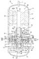
図1に示すように、回転式圧縮機(10)は、縦長で密閉容器状のケーシング(11)を備えている。ケーシング(11)は、縦長の円筒状に形成された胴部(12)と、椀状に形成されて、胴部(12)の両端に外側に凸に配設される一対の端板部(13)とによって構成されている。ケーシング(11)の内部には、電動機(20)と、第1圧縮機構(30)及び第2圧縮機構(40)を有して冷媒を二段圧縮する圧縮機部(50)とが収納されている。なお、本実施形態1では、第1圧縮機構(30)が低段側圧縮機構を構成し、第2圧縮機構(40)が高段側圧縮機構を構成する。 As shown in FIG. 1, the rotary compressor (10) includes a casing (11) that is vertically long and sealed. The casing (11) has a body portion (12) formed in a vertically long cylindrical shape, and a pair of end plate portions (which are formed in a bowl shape and are provided on both ends of the body portion (12) so as to protrude outward. 13). Housed in the casing (11) are an electric motor (20) and a compressor section (50) having a first compression mechanism (30) and a second compression mechanism (40) and compressing the refrigerant in two stages. ing. In the first embodiment, the first compression mechanism (30) constitutes a low-stage compression mechanism, and the second compression mechanism (40) constitutes a high-stage compression mechanism.
ケーシング(11)の胴部(12)には、低段側の第1圧縮機構(30)に接続される第1吸入管(14)及び第1吐出管(15)が、該胴部(12)を厚み方向に貫通するように設けられている。また、胴部(12)には、高段側の第2圧縮機構(40)に接続される第2吸入管(16)が、該胴部(12)を貫通するように設けられている。さらに、胴部(12)の上方側を塞ぐ端板部(13)には、第2吐出管(17)が該端板部(13)を貫通するように設けられ、該第2吐出管(17)はケーシング(11)の内部空間(S10)と連通している。なお、図示を省略するが、第1吐出管(15)と第2吸入管(16)とは、ケーシング(11)の外部において接続されている。 The body (12) of the casing (11) has a first suction pipe (14) and a first discharge pipe (15) connected to the first compression mechanism (30) on the lower stage side. ) In the thickness direction. The body (12) is provided with a second suction pipe (16) connected to the second compression mechanism (40) on the higher stage side so as to penetrate the body (12). Furthermore, a second discharge pipe (17) is provided in the end plate part (13) that closes the upper side of the body part (12) so as to penetrate the end plate part (13), and the second discharge pipe ( 17) communicates with the internal space (S10) of the casing (11). Although not shown, the first discharge pipe (15) and the second suction pipe (16) are connected to the outside of the casing (11).
このような構成により、回転式圧縮機(10)は、高段側の第2圧縮機構(40)において圧縮された冷媒がケーシング(11)の内部空間(S10)に吐出され、第2吐出管(17)を介してケーシング(11)の外部へ排出されるように構成されている。つまり、回転式圧縮機(10)は、ケーシング(11)の内部空間(S10)が高圧圧力状態となる、いわゆる高圧ドーム型の圧縮機に構成されている。 With such a configuration, in the rotary compressor (10), the refrigerant compressed in the second compression mechanism (40) on the high stage side is discharged into the internal space (S10) of the casing (11), and the second discharge pipe It is configured to be discharged to the outside of the casing (11) via (17). That is, the rotary compressor (10) is a so-called high pressure dome type compressor in which the internal space (S10) of the casing (11) is in a high pressure state.
ケーシング(11)の内部には、胴部(12)と平行に延びる駆動軸(23)が設けられている。電動機(20)及び圧縮機部(50)は、該駆動軸(23)を介して連結されている。密閉容器状のケーシング(11)の底部には、圧縮機部(50)の各摺動部に供給される潤滑油を貯留する油溜まり(18)が形成されている。 A drive shaft (23) extending in parallel with the body (12) is provided inside the casing (11). The electric motor (20) and the compressor unit (50) are connected via the drive shaft (23). An oil reservoir (18) for storing lubricating oil supplied to each sliding portion of the compressor section (50) is formed at the bottom of the sealed container-shaped casing (11).
駆動軸(23)は、主軸部(24)と2つの偏心部(25,26)とを有している。駆動軸(23)では、2つの偏心部(25,26)が所定の間隔を介して軸方向に並設されている。本実施形態では、上側偏心部(26)は、主軸部(24)の中央寄りに設けられ、下側偏心部(25)は、主軸部(24)の下端寄りの位置に設けられている。両偏心部(25,26)は、主軸部(24)よりも大径の円柱状に形成され、それぞれ軸心が主軸部(24)の軸心に対して偏心している。また、上側偏心部(26)と下側偏心部(25)とは、主軸部(24)の軸心を中心として互いに180°位相がずれるように形成されている。また、駆動軸(23)では、上側偏心部(26)と下側偏心部(25)との間の部位が中間軸部(27)を構成している。 The drive shaft (23) has a main shaft portion (24) and two eccentric portions (25, 26). In the drive shaft (23), two eccentric portions (25, 26) are arranged in parallel in the axial direction with a predetermined interval. In the present embodiment, the upper eccentric portion (26) is provided near the center of the main shaft portion (24), and the lower eccentric portion (25) is provided at a position near the lower end of the main shaft portion (24). Both eccentric portions (25, 26) are formed in a columnar shape having a larger diameter than the main shaft portion (24), and the respective shaft centers are eccentric with respect to the shaft center of the main shaft portion (24). Further, the upper eccentric part (26) and the lower eccentric part (25) are formed so that their phases are shifted from each other by 180 ° around the axis of the main shaft part (24). In the drive shaft (23), a portion between the upper eccentric portion (26) and the lower eccentric portion (25) constitutes an intermediate shaft portion (27).
駆動軸(23)の下端には、油溜まり(18)に浸漬する給油ポンプ(28)が設けられている。駆動軸(23)の内部には、給油ポンプ(28)が吸い上げた潤滑油が流通する軸内流路(61a)が軸方向に延びて形成されている。軸内流路(61a)は、油溜まり(18)の潤滑油を圧縮機構(30,40)の各摺動部へ供給するための油供給路(61)の一部を構成している。また、上記給油ポンプ(28)と油供給路(61)とは、第1圧縮機構(30)及び第2圧縮機構(40)のそれぞれの圧縮室等へ潤滑油を供給するための油供給機構(60)の一部を構成している。この油供給機構(60)の詳細については後述する。 An oil supply pump (28) immersed in the oil sump (18) is provided at the lower end of the drive shaft (23). In the drive shaft (23), an in-shaft channel (61a) through which the lubricating oil sucked up by the oil pump (28) flows is formed extending in the axial direction. The in-shaft channel (61a) constitutes a part of an oil supply channel (61) for supplying the lubricating oil in the oil reservoir (18) to each sliding portion of the compression mechanism (30, 40). The oil supply pump (28) and the oil supply path (61) include an oil supply mechanism for supplying lubricating oil to the respective compression chambers of the first compression mechanism (30) and the second compression mechanism (40). Part of (60). Details of the oil supply mechanism (60) will be described later.
電動機(20)は、ステータ(21)とロータ(22)とを備えている。ステータ(21)は、ケーシング(11)の胴部(12)に固定されている。一方、ロータ(22)は、ステータ(21)の内側に配置され、駆動軸(23)の主軸部(24)に連結されている。電動機(20)は、インバータ装置からの出力周波数が制御されることで、駆動軸(23)の回転速度を調整できるように構成されている。つまり、本実施形態の回転式圧縮機(10)は、容量が可変に構成されている。 The electric motor (20) includes a stator (21) and a rotor (22). The stator (21) is fixed to the body (12) of the casing (11). On the other hand, the rotor (22) is disposed inside the stator (21) and is coupled to the main shaft portion (24) of the drive shaft (23). The electric motor (20) is configured to be able to adjust the rotational speed of the drive shaft (23) by controlling the output frequency from the inverter device. That is, the capacity of the rotary compressor (10) of the present embodiment is variable.
圧縮機部(50)は、第1圧縮機構(30)と第2圧縮機構(40)とミドルプレート(51)とが一体的に組み込まれて構成されている。圧縮機部(50)では、軸方向の下側から上側に向かって、第1圧縮機構(30)、ミドルプレート(51)、第2圧縮機構(40)が順に並んでいる。 The compressor section (50) is configured by integrating a first compression mechanism (30), a second compression mechanism (40), and a middle plate (51). In the compressor section (50), the first compression mechanism (30), the middle plate (51), and the second compression mechanism (40) are arranged in this order from the lower side to the upper side in the axial direction.
図2及び図3に示すように、第1圧縮機構(30)は、第1シリンダ(31)と第1ピストン(32)とを有し、第1シリンダ(31)と第1ピストン(32)との間に圧縮室を構成している。第1ピストン(32)は、下側偏心部(25)に外嵌して回転駆動される可動部材を構成している。第1シリンダ(31)は、ケーシング(11)に固定される固定部材を構成している。これにより、第1シリンダ(31)と第1ピストン(32)とは、相対的に偏心回転運動を行う。 As shown in FIGS. 2 and 3, the first compression mechanism (30) includes a first cylinder (31) and a first piston (32), and the first cylinder (31) and the first piston (32). A compression chamber is formed between the two. The first piston (32) constitutes a movable member that is externally fitted to the lower eccentric portion (25) and is rotationally driven. The first cylinder (31) constitutes a fixing member fixed to the casing (11). As a result, the first cylinder (31) and the first piston (32) relatively eccentrically rotate.
第1シリンダ(31)は、中央に軸受部が形成された平板状の鏡板部(31a)と、該鏡板部(31a)から上方に突出するように形成された筒状の外側シリンダ部(31b)及び内側シリンダ部(31c)とを備えている。外側シリンダ部(31b)は、鏡板部(31a)の径方向外側部位に突設される環状の外歯部を構成している。内側シリンダ部(31c)は、鏡板部(31a)の径方向内側部位に突設される環状の内歯部を構成している。外側シリンダ部(31b)及び内側シリンダ部(31c)は、駆動軸(23)の軸心と同軸となっている。 The first cylinder (31) includes a flat end plate portion (31a) having a bearing portion formed in the center, and a cylindrical outer cylinder portion (31b) formed so as to protrude upward from the end plate portion (31a). ) And an inner cylinder part (31c). The outer cylinder part (31b) constitutes an annular external tooth part protruding from the radially outer part of the end plate part (31a). The inner cylinder part (31c) constitutes an annular inner tooth part protruding from the radially inner part of the end plate part (31a). The outer cylinder part (31b) and the inner cylinder part (31c) are coaxial with the axis of the drive shaft (23).
第1シリンダ(31)では、内側シリンダ部(31c)の内側に第1軸受収容室(39)が形成される。第1軸受収容室(39)には、第1ピストン(32)の軸受部(32c)が収容される。内側シリンダ部(31c)の外周面と外側シリンダ部(31b)の内周面との間には、環状の第1シリンダ室(S11,S12)が形成される。第1シリンダ室(S11,S12)には、第1ピストン(32)の環状ピストン部(32b)が収容される。これにより、第1シリンダ室(S11,S12)には、環状ピストン部(32b)の外側に外側圧縮室(S11)が区画され、環状ピストン部(32b)の内側に内側圧縮室(S12)が区画される。 In the first cylinder (31), a first bearing housing chamber (39) is formed inside the inner cylinder part (31c). The bearing portion (32c) of the first piston (32) is housed in the first bearing housing chamber (39). An annular first cylinder chamber (S11, S12) is formed between the outer peripheral surface of the inner cylinder part (31c) and the inner peripheral surface of the outer cylinder part (31b). An annular piston portion (32b) of the first piston (32) is accommodated in the first cylinder chamber (S11, S12). Thereby, in the first cylinder chamber (S11, S12), the outer compression chamber (S11) is defined outside the annular piston portion (32b), and the inner compression chamber (S12) is located inside the annular piston portion (32b). Partitioned.
第1シリンダ(31)は、鏡板部(31a)及び外側シリンダ部(31b)がケーシング(11)の胴部(12)の内面に溶接されることにより固定されている。つまり、第1シリンダ(31)の鏡板部(31a)は、固定側となる固定側鏡板部を構成している。また、第1シリンダ(31)の内部には、駆動軸(23)の主軸部(24)が挿通される軸受部(31d)が形成される。駆動軸(23)の主軸部(24)は、軸受部(31d)によって回転自在に支持されている。 The first cylinder (31) is fixed by welding the end plate part (31a) and the outer cylinder part (31b) to the inner surface of the body part (12) of the casing (11). That is, the end plate part (31a) of the first cylinder (31) constitutes a fixed side end plate part serving as a fixed side. A bearing portion (31d) through which the main shaft portion (24) of the drive shaft (23) is inserted is formed in the first cylinder (31). The main shaft portion (24) of the drive shaft (23) is rotatably supported by the bearing portion (31d).
第1シリンダ(31)の鏡板部(31a)には、外周面から径方向の内側向きに延びる第1吸入ポート(14a)が形成されている。この第1吸入ポート(14a)の一端は、外側圧縮室(S11)及び内側圧縮室(S12)に連通するように構成され、他端には第1吸入管(14)が接続されている。つまり、第1吸入ポート(14a)は第1吸入管(14)から外側圧縮室(S11)及び内側圧縮室(S12)に吸入される冷媒を流通させる第1吸入通路を構成している。 A first suction port (14a) extending radially inward from the outer peripheral surface is formed in the end plate portion (31a) of the first cylinder (31). One end of the first suction port (14a) is configured to communicate with the outer compression chamber (S11) and the inner compression chamber (S12), and the first suction pipe (14) is connected to the other end. That is, the first suction port (14a) constitutes a first suction passage through which the refrigerant sucked from the first suction pipe (14) flows into the outer compression chamber (S11) and the inner compression chamber (S12).
第1シリンダ(31)の鏡板部(31a)には、外周面から径方向の内側向きに延びる第1吐出ポート(15a)が形成されている。この第1吐出ポート(15a)の一端は、外側圧縮室(S11)及び内側圧縮室(S12)に連通するように構成され、他端には第1吐出管(15)が接続されている。具体的には、第1吐出ポート(15a)には、外側圧縮室(S11)及び内側圧縮室(S12)の吐出口(35,36)が開口し、該両吐出口(35,36)には吐出弁(37,38)が設けられている。外側圧縮室(S11)の吐出弁(37)は、該外側圧縮室(S11)の高圧室(S11H)と第1吐出ポート(15a)との差圧が設定値に達すると吐出口(35)を開くように構成されている。同様に、内側圧縮室(S12)の吐出弁(38)は、該内側圧縮室(S12)の高圧室(S12H)と第1吐出ポート(15a)との差圧が設定値に達すると吐出口(36)を開くように構成されている。 A first discharge port (15a) extending radially inward from the outer peripheral surface is formed in the end plate portion (31a) of the first cylinder (31). One end of the first discharge port (15a) is configured to communicate with the outer compression chamber (S11) and the inner compression chamber (S12), and the first discharge pipe (15) is connected to the other end. Specifically, the discharge ports (35, 36) of the outer compression chamber (S11) and the inner compression chamber (S12) are opened in the first discharge port (15a), and both the discharge ports (35, 36) are opened. Are provided with discharge valves (37, 38). When the differential pressure between the high pressure chamber (S11H) of the outer compression chamber (S11) and the first discharge port (15a) reaches a set value, the discharge valve (37) of the outer compression chamber (S11) Is configured to open. Similarly, the discharge valve (38) of the inner compression chamber (S12) has a discharge port when the differential pressure between the high pressure chamber (S12H) of the inner compression chamber (S12) and the first discharge port (15a) reaches a set value. (36) is configured to open.
第1ピストン(32)は、平板状の鏡板部(32a)と、該鏡板部(32a)の径方向外側部位に突設される環状の環状ピストン部(32b)と、鏡板部(32a)の径方向内側部位に突設される筒状の軸受部(32c)とを備えている。第1ピストン(32)の鏡板部(32a)は、可動側となる可動側鏡板部を構成している。環状ピストン部(32b)は、円環の一部分が分断されたC型形状に形成され、第1シリンダ室(S11,S12)に収容される。軸受部(32c)は、駆動軸(23)の下側偏心部(25)に外嵌し、第1軸受収容室(39)に収容されている。第1軸受収容室(39)では、内側シリンダ部(31c)の内周面に対して軸受部(32c)が一定の間隔を確保しながら偏心回転する。これにより、内側シリンダ部(31c)の内部では、流体が実質的に圧縮されることはない。つまり、第1軸受収容室(39)は、冷媒の圧縮に寄与しない、いわゆる無効空間を構成している。 The first piston (32) includes a plate-shaped end plate portion (32a), an annular annular piston portion (32b) protruding from a radially outer portion of the end plate portion (32a), and an end plate portion (32a). And a cylindrical bearing portion (32c) protruding from the radially inner portion. The end plate portion (32a) of the first piston (32) constitutes a movable end plate portion that is a movable side. The annular piston portion (32b) is formed in a C shape in which a part of the annular ring is divided, and is accommodated in the first cylinder chamber (S11, S12). The bearing portion (32c) is fitted on the lower eccentric portion (25) of the drive shaft (23) and is accommodated in the first bearing accommodating chamber (39). In the first bearing housing chamber (39), the bearing portion (32c) rotates eccentrically while ensuring a constant interval with respect to the inner peripheral surface of the inner cylinder portion (31c). Thereby, the fluid is not substantially compressed inside the inner cylinder part (31c). That is, the first bearing housing chamber (39) forms a so-called invalid space that does not contribute to the compression of the refrigerant.
図2に示すように、第1圧縮機構(30)は、第1シリンダ室(S11,S12)の外側圧縮室(S11)と内側圧縮室(S12)とを更に高圧室(S11H,S12H)と低圧室(S11L,S12L)とに区画するブレード(33)を備えている。第1ブレード(33)は、第1シリンダ室(S11,S12)の径方向に、外側シリンダ部(31b)の内周面から内側シリンダ部(31c)の外周面に亘って延びている。そして、第1ブレード(33)は、環状ピストン部(32b)の分断箇所を挿通して第1シリンダ室(S11,S12)を高圧室(S11H,S12H)と低圧室(S11L,S12L)とに区画するように構成されている。なお、本実施形態では、第1ブレード(33)は、外側シリンダ部(31b)及び内側シリンダ部(31c)と一体形成されているが、該両シリンダ部(31b,31c)と別部材として形成し、これらに固定するものであってもよい。 As shown in FIG. 2, the first compression mechanism (30) includes an outer compression chamber (S11) and an inner compression chamber (S12) of the first cylinder chamber (S11, S12), and a high pressure chamber (S11H, S12H). A blade (33) is provided that partitions into a low-pressure chamber (S11L, S12L). The first blade (33) extends from the inner peripheral surface of the outer cylinder portion (31b) to the outer peripheral surface of the inner cylinder portion (31c) in the radial direction of the first cylinder chamber (S11, S12). Then, the first blade (33) is inserted through the part where the annular piston part (32b) is divided, and the first cylinder chamber (S11, S12) is divided into the high pressure chamber (S11H, S12H) and the low pressure chamber (S11L, S12L). It is configured to partition. In the present embodiment, the first blade (33) is integrally formed with the outer cylinder part (31b) and the inner cylinder part (31c), but is formed as a separate member from both the cylinder parts (31b, 31c). And you may fix to these.
第1圧縮機構(30)は、環状ピストン部(32b)の分断箇所に設けられ、第1ピストン(32)と第1ブレード(33)とを揺動可能に連結する第1揺動ブッシュ(34)を備えている。第1揺動ブッシュ(34)は、第1ブレード(33)に対して高圧室(S11H,S12H)側に位置する吐出側ブッシュ(34a)と、該第1ブレード(33)に対して低圧室(S11L,S12L)側に位置する吸入側ブッシュ(34b)とから構成されている。この吐出側ブッシュ(34a)及び吸入側ブッシュ(34b)は、いずれも断面形状が略半円形の同一形状に形成されている。該両ブッシュ(34a,34b)の対向面の間には、上記第1ブレード(33)が進退自在に挟まれている。そして、第1揺動ブッシュ(34)は、該第1ブレード(33)を挟み込んだ状態において、第1ピストン(32)に対して揺動可能に形成されている。なお、両ブッシュ(34a,34b)は一部において連結されて一体的に形成されていてもよい。 The first compression mechanism (30) is provided at a portion where the annular piston portion (32b) is divided, and a first swing bush (34) that connects the first piston (32) and the first blade (33) so as to be swingable. ). The first swing bush (34) includes a discharge side bush (34a) positioned on the high pressure chamber (S11H, S12H) side with respect to the first blade (33), and a low pressure chamber with respect to the first blade (33). It is comprised from the suction side bush (34b) located in the (S11L, S12L) side. Both the discharge side bush (34a) and the suction side bush (34b) are formed in the same shape having a substantially semicircular cross section. The first blade (33) is sandwiched between the opposing surfaces of the bushes (34a, 34b) so as to freely advance and retract. The first swing bush (34) is swingable with respect to the first piston (32) when the first blade (33) is sandwiched. In addition, both bushes (34a, 34b) may be partially connected and integrally formed.
第1圧縮機構(30)では、第1ピストン(32)が第1シリンダ(31)に対して偏心回転運動を行う。この偏心回転運動では、環状ピストン部(32b)の外周面と外側シリンダ部(31b)の内周面とが実質的に1点で摺接し、その摺接点と位相が180°ずれた位置において環状ピストン部(32b)の内周面と内側シリンダ部(31c)の外周面とが実質的に1点で摺接する。 In the first compression mechanism (30), the first piston (32) performs an eccentric rotational motion with respect to the first cylinder (31). In this eccentric rotational movement, the outer peripheral surface of the annular piston part (32b) and the inner peripheral surface of the outer cylinder part (31b) are slidably contacted at one point, and are annularly moved at a position where the phase of the slidable contact is shifted by 180 °. The inner peripheral surface of the piston portion (32b) and the outer peripheral surface of the inner cylinder portion (31c) are slidably contacted at one point.
第2圧縮機構(40)は、上記第1圧縮機構(30)と同様の機械要素によって構成されている。また、第2圧縮機構(40)は、ミドルプレート(51)を挟んで第1圧縮機構(30)を反転させた状態で設けられている。なお、図2では、第2圧縮機構(40)の構成要素に関する符号を括弧内に示している。 The second compression mechanism (40) is composed of the same mechanical elements as the first compression mechanism (30). The second compression mechanism (40) is provided in a state where the first compression mechanism (30) is reversed with the middle plate (51) interposed therebetween. In FIG. 2, reference numerals related to the components of the second compression mechanism (40) are shown in parentheses.
具体的には、第2圧縮機構(40)は、第2シリンダ(41)と第2ピストン(42)とを有し、第2シリンダ(41)と第2ピストン(42)との間に圧縮室を構成している。第2ピストン(42)は、上側偏心部(26)に外嵌して回転駆動される可動部材を構成している。第2シリンダ(41)は、ケーシング(11)に固定される固定部材を構成している。これにより、第2シリンダ(41)と第2ピストン(42)とは、相対的に偏心回転運動を行う。なお、上述のように、下側偏心部(25)と上側偏心部(26)とは、180°位相がずれている。このため、これらの偏心部(25,26)に駆動される第1ピストン(32)及び第2ピストン(42)も、互いに180°位相がずれた状態を保持しながら偏心回転する。 Specifically, the second compression mechanism (40) has a second cylinder (41) and a second piston (42), and compresses between the second cylinder (41) and the second piston (42). Make up the room. The second piston (42) constitutes a movable member that is externally fitted to the upper eccentric portion (26) and is rotationally driven. The second cylinder (41) constitutes a fixing member fixed to the casing (11). Thereby, the second cylinder (41) and the second piston (42) relatively eccentrically rotate. As described above, the lower eccentric portion (25) and the upper eccentric portion (26) are 180 ° out of phase. Therefore, the first piston (32) and the second piston (42) driven by these eccentric portions (25, 26) also rotate eccentrically while maintaining a state where the phases are shifted from each other by 180 °.
第2シリンダ(41)は、平板状の鏡板部(41a)と、該鏡板部(41a)から下方に突出して形成された筒状の外側シリンダ部(41b)及び内側シリンダ部(41c)とを備えている。外側シリンダ部(41b)は、鏡板部(41a)の径方向外側部位に突設される環状の外歯部を構成している。内側シリンダ部(41c)は、鏡板部(41a)の径方向内側部位に突設される環状の内歯部を構成している。外側シリンダ部(41b)及び内側シリンダ部(41c)は、駆動軸(23)の軸心と同軸となっている。 The second cylinder (41) includes a plate-shaped end plate portion (41a), and a cylindrical outer cylinder portion (41b) and an inner cylinder portion (41c) formed to protrude downward from the end plate portion (41a). I have. The outer cylinder part (41b) constitutes an annular external tooth part protruding from the radially outer part of the end plate part (41a). The inner cylinder part (41c) constitutes an annular inner tooth part protruding from the radially inner part of the end plate part (41a). The outer cylinder part (41b) and the inner cylinder part (41c) are coaxial with the axis of the drive shaft (23).
第2シリンダ(41)では、内側シリンダ部(41c)の内側に第2軸受収容室(49)が形成される。第2軸受収容室(49)には、第2ピストン(42)の軸受部(42c)が収容される。内側シリンダ部(41c)の外周面と外側シリンダ部(41b)の内周面との間には、環状の第2シリンダ室(S21,S22)が形成される。第2シリンダ室(S21,S22)には、第2ピストン(42)の環状ピストン部(42b)が収容される。これにより、第2シリンダ室(S21,S22)には、環状ピストン部(42b)の外側に外側圧縮室(S21)が区画され、環状ピストン部(42b)の内側に内側圧縮室(S22)が区画される。 In the second cylinder (41), a second bearing housing chamber (49) is formed inside the inner cylinder part (41c). The bearing portion (42c) of the second piston (42) is accommodated in the second bearing accommodation chamber (49). An annular second cylinder chamber (S21, S22) is formed between the outer peripheral surface of the inner cylinder part (41c) and the inner peripheral surface of the outer cylinder part (41b). The second cylinder chamber (S21, S22) accommodates the annular piston portion (42b) of the second piston (42). Thereby, in the second cylinder chamber (S21, S22), the outer compression chamber (S21) is defined outside the annular piston portion (42b), and the inner compression chamber (S22) is located inside the annular piston portion (42b). Partitioned.
第2シリンダ(41)は、鏡板部(41a)及び外側シリンダ部(41b)がケーシング(11)の胴部(12)の内面に溶接されることにより固定されている。つまり、第2シリンダ(41)の鏡板部(41a)は、固定側となる固定側鏡板部を構成している。また、第2シリンダ(41)の内部には、駆動軸(23)の主軸部(24)が挿通される軸受部(41d)が形成される。駆動軸(23)の主軸部(24)は、軸受部(41d)によって回転自在に支持されている。 The second cylinder (41) is fixed by welding the end plate part (41a) and the outer cylinder part (41b) to the inner surface of the body part (12) of the casing (11). That is, the end plate part (41a) of the second cylinder (41) constitutes a fixed side end plate part serving as a fixed side. In addition, a bearing portion (41d) into which the main shaft portion (24) of the drive shaft (23) is inserted is formed inside the second cylinder (41). The main shaft portion (24) of the drive shaft (23) is rotatably supported by the bearing portion (41d).
第2シリンダ(41)の鏡板部(41a)には、外周面から径方向の内側向きに延びる第2吸入ポート(16a)が形成されている。この第2吸入ポート(16a)の一端は、外側圧縮室(S21)及び内側圧縮室(S22)に連通するように構成され、他端には上記第2吸入管(16)が接続されている。つまり、該第2吸入ポート(16a)は第2吸入管(16)から外側圧縮室(S21)及び内側圧縮室(S22)に吸入される冷媒を流通させる第2吸入通路を構成している。 A second suction port (16a) extending radially inward from the outer peripheral surface is formed in the end plate portion (41a) of the second cylinder (41). One end of the second suction port (16a) is configured to communicate with the outer compression chamber (S21) and the inner compression chamber (S22), and the second suction pipe (16) is connected to the other end. . That is, the second suction port (16a) constitutes a second suction passage through which the refrigerant sucked from the second suction pipe (16) flows into the outer compression chamber (S21) and the inner compression chamber (S22).
第2シリンダ(41)の鏡板部(41a)には、上面から下方に向かって延びる第2吐出ポート(17a)が形成されている。この第2吐出ポート(17a)の一端は、外側圧縮室(S21)及び内側圧縮室(S22)に連通するように構成され、他端はケーシング(11)の内部空間(S10)に開口している。具体的には、第2吐出ポート(17a)には、外側圧縮室(S21)及び内側圧縮室(S22)の吐出口(45,46)が開口し、該両吐出口(45,46)には吐出弁(47,48)が設けられている。外側圧縮室(S21)の吐出弁(47)は、該外側圧縮室(S21)の高圧室(S21H)と第2吐出ポート(17a)との差圧が設定値に達すると吐出口(45)を開くように構成されている。同様に、内側圧縮室(S22)の吐出弁(48)は、該内側圧縮室(S22)の高圧室(S22H)と第2吐出ポート(17a)との差圧が設定値に達すると吐出口(46)を開くように構成されている。 A second discharge port (17a) extending downward from the upper surface is formed in the end plate portion (41a) of the second cylinder (41). One end of the second discharge port (17a) is configured to communicate with the outer compression chamber (S21) and the inner compression chamber (S22), and the other end opens into the internal space (S10) of the casing (11). Yes. Specifically, the discharge port (45, 46) of the outer compression chamber (S21) and the inner compression chamber (S22) is opened in the second discharge port (17a), and both the discharge ports (45, 46) are opened. Are provided with discharge valves (47, 48). When the pressure difference between the high pressure chamber (S21H) of the outer compression chamber (S21) and the second discharge port (17a) reaches a set value, the discharge valve (47) of the outer compression chamber (S21) Is configured to open. Similarly, when the pressure difference between the high pressure chamber (S22H) of the inner compression chamber (S22) and the second discharge port (17a) reaches a set value, the discharge valve (48) of the inner compression chamber (S22) (46) is configured to open.
第2ピストン(42)は、平板状の鏡板部(42a)と、該鏡板部(42a)の径方向外側部位に突設される環状の環状ピストン部(42b)と、該鏡板部(42a)の径方向内側部位に突設される筒状の軸受部(42c)とを備えている。環状ピストン部(42b)は、円環の一部分が分断されたC型形状に形成され、第2シリンダ室(S21,S22)に収容される。軸受部(42c)は、駆動軸(23)の上側偏心部(26)に外嵌し、第2軸受収容室(49)に収容されている。第2軸受収容室(49)では、内側シリンダ部(41c)の内周面に対して軸受部(42c)が一定の間隔を確保しながら偏心回転する。これにより、内側シリンダ部(41c)の内部では、流体が実質的に圧縮されることはない。つまり、第2軸受収容室(49)は、冷媒の圧縮に寄与しない、いわゆる無効空間を構成している。 The second piston (42) includes a plate-shaped end plate portion (42a), an annular annular piston portion (42b) projecting from a radially outer portion of the end plate portion (42a), and the end plate portion (42a). And a cylindrical bearing portion (42c) projecting from the radially inner portion. The annular piston portion (42b) is formed in a C shape in which a part of the annular ring is divided, and is accommodated in the second cylinder chamber (S21, S22). The bearing portion (42c) is fitted on the upper eccentric portion (26) of the drive shaft (23) and is accommodated in the second bearing accommodating chamber (49). In the second bearing housing chamber (49), the bearing portion (42c) rotates eccentrically with respect to the inner peripheral surface of the inner cylinder portion (41c) while ensuring a constant interval. Thereby, the fluid is not substantially compressed inside the inner cylinder part (41c). That is, the second bearing housing chamber (49) forms a so-called invalid space that does not contribute to the compression of the refrigerant.
第2圧縮機構(40)は、第2シリンダ室(S21,S22)の外側圧縮室(S21)と内側圧縮室(S22)とを更に高圧室(S21H,S22H)と低圧室(S21L,S22L)とに区画するブレード(43)を備えている。第2ブレード(43)は、第2シリンダ室(S21,S22)の径方向に、外側シリンダ部(41b)の内周面から内側シリンダ部(41c)の外周面に亘って延びている。そして、第2ブレード(43)は、環状ピストン部(42b)の分断箇所を挿通して第2シリンダ室(S21,S22)を高圧室(S21H,S22H)と低圧室(S21L,S22L)とに区画するように構成されている。なお、本実施形態では、第2ブレード(43)は、外側シリンダ部(41b)及び内側シリンダ部(41c)と一体形成されているが、該両シリンダ部(41b,41c)と別部材として形成し、これらに固定するものであってもよい。 The second compression mechanism (40) includes an outer compression chamber (S21) and an inner compression chamber (S22) of the second cylinder chamber (S21, S22), a higher pressure chamber (S21H, S22H), and a lower pressure chamber (S21L, S22L). And a blade (43) that is divided into two. The second blade (43) extends from the inner peripheral surface of the outer cylinder portion (41b) to the outer peripheral surface of the inner cylinder portion (41c) in the radial direction of the second cylinder chamber (S21, S22). Then, the second blade (43) is inserted through the part where the annular piston (42b) is divided, and the second cylinder chamber (S21, S22) is divided into a high pressure chamber (S21H, S22H) and a low pressure chamber (S21L, S22L). It is configured to partition. In the present embodiment, the second blade (43) is integrally formed with the outer cylinder part (41b) and the inner cylinder part (41c), but is formed as a separate member from both the cylinder parts (41b, 41c). And you may fix to these.
第2圧縮機構(40)は、環状ピストン部(42b)の分断箇所に設けられ、第2ピストン(42)と第2ブレード(43)とを揺動可能に連結する第2揺動ブッシュ(44)を備えている。第2揺動ブッシュ(44)は、第2ブレード(43)に対して高圧室(S21H,S22H)側に位置する吐出側ブッシュ(44a)と、該第2ブレード(43)に対して低圧室(S21L,S22L)側に位置する吸入側ブッシュ(44b)とから構成されている。この吐出側ブッシュ(44a)及び吸入側ブッシュ(44b)は、いずれも断面形状が略半円形の同一形状に形成されている。該両ブッシュ(44a,44b)の対向面の間には、上記第2ブレード(43)が進退自在に挟まれている。そして、第2揺動ブッシュ(44)は、該第2ブレード(43)を挟み込んだ状態において、第2ピストン(42)に対して揺動可能に形成されている。なお、両ブッシュ(44a,44b)は一部において連結されて一体的に形成されていてもよい。 The second compression mechanism (40) is provided at a portion where the annular piston portion (42b) is divided, and a second swing bush (44) that connects the second piston (42) and the second blade (43) so as to be swingable. ). The second swing bush (44) includes a discharge side bush (44a) positioned on the high pressure chamber (S21H, S22H) side with respect to the second blade (43), and a low pressure chamber with respect to the second blade (43). It is comprised from the suction side bush (44b) located in the (S21L, S22L) side. The discharge-side bush (44a) and the suction-side bush (44b) are both formed in the same shape with a substantially semicircular cross section. The second blade (43) is sandwiched between the opposed surfaces of the bushes (44a, 44b) so as to freely advance and retract. The second swing bush (44) is swingable with respect to the second piston (42) in a state where the second blade (43) is sandwiched. In addition, both bushes (44a, 44b) may be partially connected and integrally formed.
第2圧縮機構(40)では、第2ピストン(42)が第2シリンダ(41)に対して偏心回転運動を行う。この偏心回転運動では、環状ピストン部(42b)の外周面と外側シリンダ部(41b)の内周面とが実質的に1点で摺接し、その摺接点と位相が180°ずれた位置において環状ピストン部(42b)の内周面と内側シリンダ部(41c)の外周面とが実質的に1点で摺接する。 In the second compression mechanism (40), the second piston (42) performs eccentric rotational movement with respect to the second cylinder (41). In this eccentric rotational motion, the outer peripheral surface of the annular piston portion (42b) and the inner peripheral surface of the outer cylinder portion (41b) are slidably contacted at one point, and the annular contact is made at a position where the phase is 180 ° shifted from the sliding contact. The inner peripheral surface of the piston part (42b) and the outer peripheral surface of the inner cylinder part (41c) are slidably contacted at one point.
ミドルプレート(51)は、第1圧縮機構(30)と第2圧縮機構(40)との間に設けられて両圧縮機構(30,40)を仕切っている。ミドルプレート(51)は、環状の平板部(51b)と、該平板部(51b)の外周縁部に形成される筒状の筒部(51a)とによって構成されている。平板部(51b)は、軸方向に扁平な環状に形成され、その内部に駆動軸(23)の中間軸部(27)が貫通している。平板部(51b)は、第1ピストン(32)の鏡板部(32a)と、第2ピストン(42)の鏡板部(42a)との間に介設されている。筒部(51a)は、ケーシング(11)の内壁に沿うように軸方向に延出する筒状に形成され、その外周面の少なくとも一部がケーシング(11)の内壁に溶接されている。以上のような構成のミドルプレート(51)は、第1圧縮機構(30)との間に第1空間(S1)を区画し、第2圧縮機構(40)との間に第2空間(S2)を区画している。 The middle plate (51) is provided between the first compression mechanism (30) and the second compression mechanism (40), and partitions both compression mechanisms (30, 40). The middle plate (51) includes an annular flat plate portion (51b) and a cylindrical tube portion (51a) formed on the outer peripheral edge of the flat plate portion (51b). The flat plate portion (51b) is formed in an annular shape that is flat in the axial direction, and the intermediate shaft portion (27) of the drive shaft (23) passes through the flat plate portion (51b). The flat plate portion (51b) is interposed between the end plate portion (32a) of the first piston (32) and the end plate portion (42a) of the second piston (42). The cylindrical portion (51a) is formed in a cylindrical shape extending in the axial direction along the inner wall of the casing (11), and at least a part of the outer peripheral surface thereof is welded to the inner wall of the casing (11). The middle plate (51) configured as described above partitions the first space (S1) between the first compression mechanism (30) and the second space (S2) between the second compression mechanism (40). ).
ミドルプレート(51)の平板部(51b)には、軸方向の両側の端面にそれぞれ環状溝が形成されており、この環状溝にそれぞれシールリング(52,53)が嵌め込まれている。具体的に、第1ピストン(32)の鏡板部(32a)とミドルプレート(51)との間には、第1シールリング(52)が設けられている。この第1シールリング(52)により、第1空間(S1)は、内側の第1内側背圧室(S3)と外側の第1外側背圧室(S4)とに区画されている。同様に、第2ピストン(42)の鏡板部(42a)とミドルプレート(51)との間には、第2シールリング(53)が設けられている。この第2シールリング(53)により、第2空間(S2)は、内側の第2内側背圧室(S5)と外側の第2外側背圧室(S6)とに区画されている。 In the flat plate portion (51b) of the middle plate (51), annular grooves are formed on both end faces in the axial direction, and seal rings (52, 53) are fitted in the annular grooves, respectively. Specifically, a first seal ring (52) is provided between the end plate portion (32a) of the first piston (32) and the middle plate (51). By the first seal ring (52), the first space (S1) is partitioned into an inner first inner back pressure chamber (S3) and an outer first outer back pressure chamber (S4). Similarly, a second seal ring (53) is provided between the end plate portion (42a) of the second piston (42) and the middle plate (51). By the second seal ring (53), the second space (S2) is partitioned into an inner second inner back pressure chamber (S5) and an outer second outer back pressure chamber (S6).
第1内側背圧室(S3)及び第2内側背圧室(S5)は、上述した軸内流路(61a)を介してケーシング(11)の内部空間(S10)と連通している。このため、第1内側背圧室(S3)及び第2内側背圧室(S5)は、軸内流路(61a)を流れる高圧の潤滑油と同等の圧力状態(換言すると、ケーシング(11)の内部空間(S10)の内圧と同等の圧力状態)となっている。このため、第1内側背圧室(S3)の内圧により、第1ピストン(32)の鏡板部(32a)を第1シリンダ(31)側へ押し付けることができる。同様に、第2内側背圧室(S5)の内圧により、第2ピストン(42)の鏡板部(42a)を第2シリンダ(41)側へ押し付けることができる。なお、本実施形態の第1外側背圧室(S4)は、第1シリンダ(31)の鏡板部(31a)に形成された低圧導入孔(55)を介して吸入ポート(14a)と連通している。このため、第1外側背圧室(S4)は、第1圧縮機構(30)に吸入される低圧冷媒の圧力と同等の圧力状態となる。これにより、第1ピストン(32)の押し付け力が大きくなり過ぎるのを抑制している。 The first inner back pressure chamber (S3) and the second inner back pressure chamber (S5) communicate with the internal space (S10) of the casing (11) through the above-described in-axis flow path (61a). For this reason, the first inner back pressure chamber (S3) and the second inner back pressure chamber (S5) are in a pressure state equivalent to the high-pressure lubricating oil flowing through the in-shaft channel (61a) (in other words, the casing (11) The internal pressure of the internal space (S10) is equal to the internal pressure). For this reason, the end plate part (32a) of the first piston (32) can be pressed against the first cylinder (31) by the internal pressure of the first inner back pressure chamber (S3). Similarly, the end plate part (42a) of the second piston (42) can be pressed against the second cylinder (41) by the internal pressure of the second inner back pressure chamber (S5). The first outer back pressure chamber (S4) of the present embodiment communicates with the suction port (14a) via the low pressure introduction hole (55) formed in the end plate part (31a) of the first cylinder (31). ing. For this reason, the first outer back pressure chamber (S4) is in a pressure state equivalent to the pressure of the low-pressure refrigerant sucked into the first compression mechanism (30). Thereby, it is suppressed that the pressing force of a 1st piston (32) becomes large too much.
図4に示すように、上記油供給機構(60)の油供給路(61)は、上述した軸内流路(61a)に加えて、第1から第4までの流出路(62,63,64,65)を有している。第1から第4までの流出路(62,63,64,65)は、駆動軸(23)の内部を径方向に延びて形成され、それらの流入端がそれぞれ軸内流路(61a)と接続している。 As shown in FIG. 4, the oil supply path (61) of the oil supply mechanism (60) includes the first to fourth outflow paths (62, 63, 64, 65). The first to fourth outflow passages (62, 63, 64, 65) are formed to extend radially inside the drive shaft (23), and their inflow ends are respectively connected to the in-shaft flow path (61a). Connected.
より詳細に、第1流出路(62)は、下側偏心部(25)の内部に形成され、第1の偏心部給油路を構成している。第1流出路(62)の流出端は、下側偏心部(25)の外周面に開口している。第2流出路(63)は、上側偏心部(26)の内部に形成され、第2の偏心部給油路を構成している。第2流出路(63)の流出端は、上側偏心部(26)の外周面に開口している。第1流出路(62)と第2流出路(63)とは、各偏心部(25,26)の偏心方向に対して90°位相がずれ、且つ互いに180°位相がずれる方向に延びている。第3流出路(64)は、駆動軸(23)のうち下側偏心部(25)の下側近傍の部位に形成されている。第3流出路(64)の流出端は、第1シリンダ(31)の内部に形成される軸受部(31d)に臨んでいる。第4流出路(65)は、駆動軸(23)のうち上側偏心部(26)の上側近傍の部位に形成されている。第4流出路(65)の流出端は、第2シリンダ(41)の内部に形成される軸受部(41d)に臨んでいる。 More specifically, the first outflow passage (62) is formed inside the lower eccentric portion (25) and constitutes a first eccentric portion oil supply passage. The outflow end of the first outflow passage (62) opens to the outer peripheral surface of the lower eccentric portion (25). The second outflow passage (63) is formed inside the upper eccentric portion (26) and constitutes a second eccentric portion oil supply passage. The outflow end of the second outflow passage (63) opens to the outer peripheral surface of the upper eccentric portion (26). The first outflow passage (62) and the second outflow passage (63) are shifted in phase by 90 ° with respect to the eccentric direction of the eccentric portions (25, 26) and extend in a direction in which the phases are shifted from each other by 180 °. . The third outflow passage (64) is formed in a portion of the drive shaft (23) near the lower side of the lower eccentric portion (25). The outflow end of the third outflow passage (64) faces a bearing portion (31d) formed inside the first cylinder (31). The fourth outflow passage (65) is formed in a portion of the drive shaft (23) near the upper side of the upper eccentric portion (26). The outflow end of the fourth outflow passage (65) faces a bearing portion (41d) formed inside the second cylinder (41).
また、上記油供給路(61)は、第1から第4までの縦溝(66,67,68,69)を有している。第1から第4までの縦溝(66,67,68,69)は、駆動軸(23)の外周面を軸方向に延びて形成されている。より詳細に、第1縦溝(66)は、下側偏心部(25)の外周面において、第1流出路(62)の流出端を跨ぐように形成されている。第1縦溝(66)の底部では、その長手方向の中間部位に第1流出路(62)の流出端が形成されている。第2縦溝(67)は、上側偏心部(26)の外周面において、第2流出路(63)の流出端を跨ぐように形成されている。第2縦溝(67)の底部では、その長手方向の中間部位に第2流出路(63)の流出端が形成されている。第3縦溝(68)は、駆動軸(23)のうち第1シリンダ(31)側の軸受部(31d)に対応する位置に形成されている。第4縦溝(69)は、駆動軸(23)のうち第2シリンダ(41)側の軸受部(41d)に対応する位置に形成されている。 The oil supply passage (61) has first to fourth longitudinal grooves (66, 67, 68, 69). The first to fourth vertical grooves (66, 67, 68, 69) are formed by extending the outer peripheral surface of the drive shaft (23) in the axial direction. More specifically, the first vertical groove (66) is formed on the outer peripheral surface of the lower eccentric portion (25) so as to straddle the outflow end of the first outflow passage (62). At the bottom of the first vertical groove (66), the outflow end of the first outflow path (62) is formed at an intermediate portion in the longitudinal direction. The second vertical groove (67) is formed on the outer peripheral surface of the upper eccentric portion (26) so as to straddle the outflow end of the second outflow passage (63). At the bottom of the second vertical groove (67), the outflow end of the second outflow passage (63) is formed at an intermediate portion in the longitudinal direction. The third vertical groove (68) is formed at a position corresponding to the bearing portion (31d) on the first cylinder (31) side of the drive shaft (23). The fourth vertical groove (69) is formed at a position corresponding to the bearing portion (41d) on the second cylinder (41) side of the drive shaft (23).
油供給路(61)は、第1環状溝(70)と第2環状溝(71)とを有している。第1環状溝(70)と第2環状溝(71)とは、駆動軸(23)の外周面の全周に亘って形成されている。第1環状溝(70)は、下側偏心部(25)の下側近傍であって、上記1縦溝(66)と第3縦溝(68)との間に形成されている。第1縦溝(66)と第3縦溝(68)とは、第1環状溝(70)を介して互いに連通している。また、第1環状溝(70)の底部には、第3流出路(64)の流出端が形成されている。第2環状溝(71)は、上側偏心部(26)の上側近傍であって、上記第2縦溝(67)と第4縦溝(69)との間に形成されている。第2縦溝(67)と第4縦溝(69)とは、第2環状溝(71)を介して互いに連通している。 The oil supply path (61) has a first annular groove (70) and a second annular groove (71). The first annular groove (70) and the second annular groove (71) are formed over the entire circumference of the outer peripheral surface of the drive shaft (23). The first annular groove (70) is near the lower side of the lower eccentric portion (25) and is formed between the first vertical groove (66) and the third vertical groove (68). The first vertical groove (66) and the third vertical groove (68) communicate with each other through the first annular groove (70). The outflow end of the third outflow passage (64) is formed at the bottom of the first annular groove (70). The second annular groove (71) is formed near the upper side of the upper eccentric part (26) and between the second vertical groove (67) and the fourth vertical groove (69). The second vertical groove (67) and the fourth vertical groove (69) communicate with each other via the second annular groove (71).
本実施形態では、上述のように、ミドルプレート(51)の内部を駆動軸(23)の中間軸部(27)が貫通している。このため、ミドルプレート(51)の内周壁と中間軸部(27)との間には、所定のクリアランスを確保するための筒状空間(S)が形成されている。本実施形態では、筒状空間(S)は、油供給機構(60)の一部を構成する。 In the present embodiment, as described above, the intermediate shaft portion (27) of the drive shaft (23) passes through the middle plate (51). For this reason, a cylindrical space (S) for ensuring a predetermined clearance is formed between the inner peripheral wall of the middle plate (51) and the intermediate shaft portion (27). In the present embodiment, the cylindrical space (S) constitutes a part of the oil supply mechanism (60).
図4〜図7に示すように、本実施形態では、油供給機構(60)は、第1圧縮機構(30)の内側圧縮室(S12)及び外側圧縮室(S11)、並びに第2圧縮機構(40)の内側圧縮室(S22)及び外側圧縮室(S21)のそれぞれへ潤滑油を供給するように構成されている。油供給機構(60)は、上記給油ポンプ(28)、油供給路(61)及び筒状空間(S)の他に、第1圧縮機構(30)及び第2圧縮機構(40)のそれぞれに形成された内溝(81)と油通路(82)と内側溝部(83)と外側溝部(84)とを有している。なお、詳細については後述するが、内側溝部(83)は本発明に係る内側油貯留室を構成し、外側溝部(84)は本発明に係る外側油貯留室を構成する。また、内溝(81)、油通路(82)、内側溝部(83)及び外側溝部(84)の構成は、第1圧縮機構(30)と第2圧縮機構(40)とで同様であるため、以下では、上側の第2圧縮機構(40)に形成された内溝(81)、油通路(82)、内側溝部(83)及び外側溝部(84)についてのみ説明する。 As shown in FIGS. 4-7, in this embodiment, the oil supply mechanism (60) includes an inner compression chamber (S12) and an outer compression chamber (S11) of the first compression mechanism (30), and a second compression mechanism. Lubricating oil is supplied to each of the inner compression chamber (S22) and the outer compression chamber (S21) of (40). The oil supply mechanism (60) is provided in each of the first compression mechanism (30) and the second compression mechanism (40) in addition to the oil supply pump (28), the oil supply path (61), and the cylindrical space (S). The formed inner groove (81), oil passage (82), inner groove (83), and outer groove (84) are formed. In addition, although mentioned later for details, an inner side groove part (83) comprises the inner side oil storage chamber which concerns on this invention, and an outer side groove part (84) comprises the outer side oil storage chamber which concerns on this invention. Further, the configurations of the inner groove (81), the oil passage (82), the inner groove portion (83) and the outer groove portion (84) are the same in the first compression mechanism (30) and the second compression mechanism (40). Hereinafter, only the inner groove (81), the oil passage (82), the inner groove (83), and the outer groove (84) formed in the upper second compression mechanism (40) will be described.
内溝(81)は、ミドルプレート(51)の上端の内周縁部に形成されている。内溝(81)は、筒状空間(S)から径方向外側に膨出する円弧状に形成されている。また、内溝(81)は、第2ピストン(42)の偏心回転時において、後述する油通路(82)の流入端(82a)の偏心軌跡を含む範囲に形成されている。従って、本実施形態では、筒状空間(S)と油通路(82)の流入端(82a)とが、回転角度に拘わらず、常時連通することになる。 The inner groove (81) is formed at the inner peripheral edge of the upper end of the middle plate (51). The inner groove (81) is formed in an arc shape bulging radially outward from the cylindrical space (S). Further, the inner groove (81) is formed in a range including an eccentric locus of an inflow end (82a) of an oil passage (82) described later when the second piston (42) rotates eccentrically. Therefore, in this embodiment, the cylindrical space (S) and the inflow end (82a) of the oil passage (82) are always in communication regardless of the rotation angle.
油通路(82)は、第2ピストン(42)の鏡板部(42a)から環状ピストン部(42b)に亘って形成されている。油通路(82)は、流入端(82a)が鏡板部(42a)における圧縮室と反対側の背面において内溝(81)に対向するように開口し、流出端(82b)が環状ピストン部(42b)の先端(歯先)において開口するように形成されている。油通路(82)の流出端(82b)の開口は、直径が0.3mm〜4mm、より好ましくは0.5mm〜2mm程度となるように形成されている。 The oil passage (82) is formed from the end plate portion (42a) of the second piston (42) to the annular piston portion (42b). The oil passage (82) opens so that the inflow end (82a) faces the inner groove (81) on the back surface opposite to the compression chamber in the end plate portion (42a), and the outflow end (82b) has an annular piston portion ( 42b) is formed to open at the tip (tooth tip). The opening of the outflow end (82b) of the oil passage (82) is formed to have a diameter of about 0.3 mm to 4 mm, more preferably about 0.5 mm to 2 mm.
上記内側溝部(83)及び外側溝部(84)は、第2シリンダ(41)の鏡板部(41a)における圧縮室側の面に形成され、内側溝部(83)が外側溝部(84)よりも径方向内側に位置するように形成されている。図5及び図6に示すように、内側溝部(83)及び外側溝部(84)は、内側シリンダ部(41c)と外側シリンダ部(41b)との間に形成された断面長円形状の溝によって構成されている。外側溝部(84)は、内側溝部(83)よりも容積が大きくなるように形成されている。また、内側溝部(83)と外側溝部(84)とは、両溝部(83,84)の合計容積が第2シリンダ室(S21,S22)の容積の0.05%〜2%の大きさとなるように、より好ましくは0.1%〜1%の大きさとなるように形成されている。 The inner groove portion (83) and the outer groove portion (84) are formed on the compression chamber side surface of the end plate portion (41a) of the second cylinder (41), and the inner groove portion (83) has a diameter larger than that of the outer groove portion (84). It is formed so as to be located inward of the direction. As shown in FIGS. 5 and 6, the inner groove portion (83) and the outer groove portion (84) are formed by a groove having an oval cross section formed between the inner cylinder portion (41c) and the outer cylinder portion (41b). It is configured. The outer groove (84) is formed to have a larger volume than the inner groove (83). The inner groove portion (83) and the outer groove portion (84) have a total volume of both the groove portions (83, 84) of 0.05% to 2% of the volume of the second cylinder chamber (S21, S22). Thus, it is more preferably formed so as to have a size of 0.1% to 1%.
また、図6に示すように、内側溝部(83)と外側溝部(84)とは、軸方向視において、第2ピストン(42)の偏心回転時における油通路(82)の流出端(82b)の軌跡(図6の二点鎖線を参照)の一部とそれぞれ重なるように形成されている。つまり、内側溝部(83)及び外側溝部(84)は、第2ピストン(42)の1回の偏心回転の際に、油通路(82)と連通する状態と連通せずに遮断された状態とが切り換わるように形成されている。また、本実施形態では、内側溝部(83)は、油通路(82)の流出端(82b)の軌跡に沿って延び、外側溝部(84)は内側シリンダ部(41c)及び外側シリンダ部(41b)の径方向に垂直な方向に延び、内側溝部(83)と外側溝部(84)とは軸方向視においてハの字状に形成されている。 As shown in FIG. 6, the inner groove portion (83) and the outer groove portion (84) are, when viewed in the axial direction, the outflow end (82b) of the oil passage (82) when the second piston (42) rotates eccentrically. Are formed so as to overlap each part of the locus (see the two-dot chain line in FIG. 6). That is, the inner groove portion (83) and the outer groove portion (84) are in a state of being disconnected without being communicated with the oil passage (82) during one eccentric rotation of the second piston (42). Are formed so as to be switched. In the present embodiment, the inner groove portion (83) extends along the locus of the outflow end (82b) of the oil passage (82), and the outer groove portion (84) includes the inner cylinder portion (41c) and the outer cylinder portion (41b). ) In the direction perpendicular to the radial direction, and the inner groove portion (83) and the outer groove portion (84) are formed in a C shape when viewed in the axial direction.
また、図7に示すように、内側溝部(83)及び外側溝部(84)は、第2ピストン(42)の1回の偏心回転の際に、外側溝部(84)と油通路(82)とが連通する角度(Δθo)が内側溝部(83)と油通路(82)とが連通する角度(Δθi)よりも大きくなるように構成されている。このように構成されることにより、第2ピストン(42)の1回の偏心回転の際に、外側溝部(84)と油通路(82)とが連通する時間は、内側溝部(83)と油通路(82)とが連通する時間よりも長くなる。なお、上記Δθo及びΔθiは、30°より大きく且つ180°未満の角度に設定されている。 Further, as shown in FIG. 7, the inner groove portion (83) and the outer groove portion (84) are separated from the outer groove portion (84) and the oil passage (82) when the second piston (42) rotates once. Is configured such that the angle (Δθo) at which the inner groove communicates is larger than the angle (Δθi) at which the inner groove (83) and the oil passage (82) communicate. With this configuration, during the one-time eccentric rotation of the second piston (42), the time during which the outer groove (84) and the oil passage (82) communicate with each other is the same as the inner groove (83) and the oil. It becomes longer than the time for the passage (82) to communicate. Note that Δθo and Δθi are set to angles larger than 30 ° and smaller than 180 °.
また、内側溝部(83)及び外側溝部(84)は、第2ピストン(42)の偏心回転中に、それぞれ対応付けられた圧縮室と油通路(82)とに交互に連通するように構成されている。具体的には、内側溝部(83)は、第2ピストン(42)の1回の偏心回転中に、油通路(82)と連通すると共に内側圧縮室(S22)との連通が遮断されて油通路(82)の潤滑油が貯留される内側貯留状態と、油通路(82)との連通が遮断されると共に内側圧縮室(S22)と連通して貯留された潤滑油を内側圧縮室(S22)に供給する内側供給状態とに切り換わる。また、外側溝部(84)は、第2ピストン(42)の1回の偏心回転中に、油通路(82)と連通すると共に外側圧縮室(S21)との連通が遮断されて油通路(82)の潤滑油が貯留される外側貯留状態と、油通路(82)との連通が遮断されると共に外側圧縮室(S21)と連通して貯留された潤滑油を外側圧縮室(S21)に供給する外側供給状態とに切り換わる。 Further, the inner groove portion (83) and the outer groove portion (84) are configured to alternately communicate with the corresponding compression chamber and oil passage (82) during the eccentric rotation of the second piston (42). ing. Specifically, the inner groove portion (83) communicates with the oil passage (82) and communicates with the inner compression chamber (S22) during one eccentric rotation of the second piston (42), and the oil is blocked. The inner storage state in which the lubricating oil in the passage (82) is stored and the communication with the oil passage (82) are blocked and the lubricating oil stored in communication with the inner compression chamber (S22) is stored in the inner compression chamber (S22 ) Is switched to the inner supply state. The outer groove portion (84) communicates with the oil passage (82) and is disconnected from the outer compression chamber (S21) during one eccentric rotation of the second piston (42), so that the oil passage (82 ) And the oil passage (82) are shut off and the stored lubricating oil in communication with the outer compression chamber (S21) is supplied to the outer compression chamber (S21). Switches to the outer supply state.
−運転動作−
次に、回転式圧縮機(10)の運転動作について説明する。まず、第1圧縮機構(30)について説明する。第1圧縮機構(30)では、低圧冷媒が圧縮されて中間圧の冷媒となる。-Driving action-
Next, the operation of the rotary compressor (10) will be described. First, the first compression mechanism (30) will be described. In the first compression mechanism (30), the low-pressure refrigerant is compressed into an intermediate-pressure refrigerant.
電動機(20)を起動すると、第1ピストン(32)の環状ピストン部(32b)が第1ブレード(33)に沿って往復運動(進退動作)を行うと共に揺動動作を行う。その際、第1揺動ブッシュ(34)は、環状ピストン部(32b)及び第1ブレード(33)に対して実質的に面接触をする。そして、環状ピストン部(32b)が外側シリンダ部(31b)及び内側シリンダ部(31c)に対して揺動しながら公転し、第1圧縮機構(30)が圧縮動作を行う。 When the electric motor (20) is started, the annular piston portion (32b) of the first piston (32) reciprocates (advances and retracts) along the first blade (33) and swings. At that time, the first swing bush (34) substantially makes surface contact with the annular piston portion (32b) and the first blade (33). Then, the annular piston portion (32b) revolves while swinging with respect to the outer cylinder portion (31b) and the inner cylinder portion (31c), and the first compression mechanism (30) performs a compression operation.
具体的には、外側圧縮室(S11)では、図2(B)の状態で低圧室(S11L)の容積がほぼ最小となり、ここから駆動軸(23)が図の矢印の方向に回転して図2(C)〜図2(A)の状態へ変化するのに伴って該低圧室(S11L)の容積が増大し、第1吸入ポート(14a)の冷媒が外側圧縮室(S11)の低圧室(S11L)に吸入される。 Specifically, in the outer compression chamber (S11), the volume of the low-pressure chamber (S11L) is almost minimized in the state of FIG. 2 (B), and from here the drive shaft (23) rotates in the direction of the arrow in the figure. The volume of the low pressure chamber (S11L) increases as the state changes from the state shown in FIGS. 2C to 2A, and the refrigerant in the first suction port (14a) becomes the low pressure in the outer compression chamber (S11). Inhaled into the chamber (S11L).
そして、上記駆動軸(23)が一回転して再び図2(B)の状態になると、上記低圧室(S11L)への冷媒の吸入が完了する。そして、該低圧室(S11L)は、冷媒が圧縮される高圧室(S11H)となり、第1ブレード(33)を隔てて新たな低圧室(S11L)が形成される。駆動軸(23)がさらに回転すると、低圧室(S11L)において冷媒の吸入が繰り返される一方、高圧室(S11H)の容積が減少し、該高圧室(S11H)で冷媒が圧縮される。高圧室(S11H)の圧力が所定値となって第1吐出ポート(15a)との差圧が設定値に達すると、吐出弁(37)が開き、高圧室(S11H)の中間圧の冷媒が第1吐出ポート(15a)を通じて第1吐出管(15)へ流出する。 Then, when the drive shaft (23) makes one revolution and enters the state of FIG. 2 (B) again, the suction of the refrigerant into the low pressure chamber (S11L) is completed. The low pressure chamber (S11L) becomes a high pressure chamber (S11H) in which the refrigerant is compressed, and a new low pressure chamber (S11L) is formed across the first blade (33). When the drive shaft (23) further rotates, the suction of the refrigerant is repeated in the low pressure chamber (S11L), while the volume of the high pressure chamber (S11H) is reduced, and the refrigerant is compressed in the high pressure chamber (S11H). When the pressure in the high pressure chamber (S11H) reaches a predetermined value and the differential pressure from the first discharge port (15a) reaches a set value, the discharge valve (37) opens, and the intermediate pressure refrigerant in the high pressure chamber (S11H) It flows out to the first discharge pipe (15) through the first discharge port (15a).
上記内側圧縮室(S22)では、図2(F)の状態で低圧室(S12L)の容積がほぼ最小となり、ここから駆動軸(23)が図の矢印の方向に回転して図2(G)〜図2(E)の状態へ変化するのに伴って該低圧室(S12L)の容積が増大し、第1吸入ポート(14a)の冷媒が内側圧縮室(S12)の低圧室(S12L)に吸入される。 In the inner compression chamber (S22), the volume of the low pressure chamber (S12L) is almost minimized in the state of FIG. 2 (F), and from here the drive shaft (23) rotates in the direction of the arrow in FIG. ) To FIG. 2 (E), the volume of the low pressure chamber (S12L) increases, and the refrigerant in the first suction port (14a) flows into the low pressure chamber (S12L) of the inner compression chamber (S12). Inhaled.
そして、上記駆動軸(23)が一回転して再び図2(F)の状態になると、上記低圧室(S12L)への冷媒の吸入が完了する。そして、該低圧室(S12L)は、冷媒が圧縮される高圧室(S12H)となり、第1ブレード(33)を隔てて新たな低圧室(S12L)が形成される。駆動軸(23)がさらに回転すると、低圧室(S12L)において冷媒の吸入が繰り返される一方、高圧室(S12H)の容積が減少し、該高圧室(S12H)で冷媒が圧縮される。高圧室(S12H)の圧力が所定値となって第1吐出ポート(15a)との差圧が設定値に達すると、吐出弁(38)が開き、高圧室(S12H)の中間圧の冷媒が第1吐出ポート(15a)を通じて第1吐出管(15)へ流出する。 Then, when the drive shaft (23) makes one revolution and again enters the state of FIG. 2 (F), the suction of the refrigerant into the low pressure chamber (S12L) is completed. The low pressure chamber (S12L) becomes a high pressure chamber (S12H) in which the refrigerant is compressed, and a new low pressure chamber (S12L) is formed across the first blade (33). When the drive shaft (23) further rotates, the suction of the refrigerant is repeated in the low pressure chamber (S12L), while the volume of the high pressure chamber (S12H) is reduced, and the refrigerant is compressed in the high pressure chamber (S12H). When the pressure in the high pressure chamber (S12H) reaches a preset value and the differential pressure from the first discharge port (15a) reaches the set value, the discharge valve (38) opens and the intermediate pressure refrigerant in the high pressure chamber (S12H) It flows out to the first discharge pipe (15) through the first discharge port (15a).
上記外側圧縮室(S11)ではほぼ図2(E)のタイミングで冷媒の吐出が開始され、内側圧縮室(S12)ではほぼ図2(A)のタイミングで吐出が開始される。つまり、外側圧縮室(S11)と内側圧縮室(S12)とでは、吐出のタイミングが約180°ずれている。第1吐出管(15)へ流出した中間圧の冷媒は、第2吸入管(16)に流入して第2圧縮機構(40)に吸入される。 In the outer compression chamber (S11), refrigerant discharge is started approximately at the timing shown in FIG. 2E, and in the inner compression chamber (S12), discharge is started approximately at the timing shown in FIG. That is, the discharge timing is shifted by about 180 ° between the outer compression chamber (S11) and the inner compression chamber (S12). The intermediate pressure refrigerant that has flowed out to the first discharge pipe (15) flows into the second suction pipe (16) and is sucked into the second compression mechanism (40).
第2圧縮機構(40)では、第1圧縮機構(30)とほぼ同様にして中間圧の冷媒が圧縮されて高圧冷媒となる。 In the second compression mechanism (40), the intermediate-pressure refrigerant is compressed into a high-pressure refrigerant in substantially the same manner as the first compression mechanism (30).
電動機(20)を起動すると、第2ピストン(42)の環状ピストン部(42b)が第2ブレード(43)に沿って往復運動(進退動作)を行うと共に揺動動作を行う。その際、第2揺動ブッシュ(44)は、環状ピストン部(42b)及び第2ブレード(43)に対して実質的に面接触をする。そして、環状ピストン部(42b)が外側シリンダ部(41b)及び内側シリンダ部(41c)に対して揺動しながら公転し、第2圧縮機構(40)が圧縮動作を行う。 When the electric motor (20) is started, the annular piston portion (42b) of the second piston (42) reciprocates (advances and retracts) along the second blade (43) and swings. At this time, the second swing bush (44) substantially makes surface contact with the annular piston portion (42b) and the second blade (43). Then, the annular piston part (42b) revolves while swinging with respect to the outer cylinder part (41b) and the inner cylinder part (41c), and the second compression mechanism (40) performs a compression operation.
具体的には、外側圧縮室(S21)では、図2(B)の状態で低圧室(S21L)の容積がほぼ最小となり、ここから駆動軸(23)が図の矢印の方向に回転して図2(C)〜図2(A)の状態へ変化するのに伴って該低圧室(S21L)の容積が増大し、第2吸入ポート(16a)の冷媒が外側圧縮室(S21)の低圧室(S21L)に吸入される。 Specifically, in the outer compression chamber (S21), the volume of the low-pressure chamber (S21L) becomes almost minimum in the state of FIG. 2 (B), and from here the drive shaft (23) rotates in the direction of the arrow in the figure. The volume of the low pressure chamber (S21L) increases with the change to the state of FIG. 2 (C) to FIG. 2 (A), and the refrigerant in the second suction port (16a) becomes the low pressure in the outer compression chamber (S21). Inhaled into the chamber (S21L).
そして、上記駆動軸(23)が一回転して再び図2(B)の状態になると、上記低圧室(S21L)への冷媒の吸入が完了する。そして、該低圧室(S21L)は、冷媒が圧縮される高圧室(S21H)となり、第2ブレード(43)を隔てて新たな低圧室(S21L)が形成される。駆動軸(23)がさらに回転すると、低圧室(S21L)において冷媒の吸入が繰り返される一方、高圧室(S21H)の容積が減少し、該高圧室(S21H)で冷媒が圧縮される。高圧室(S21H)の圧力が所定値となって第2吐出ポート(17a)との差圧が設定値に達すると、吐出弁(47)が開き、高圧室(S21H)の高圧冷媒が第2吐出ポート(17a)を通じてケーシング(11)内の内部空間(S10)へ流出する。 Then, when the drive shaft (23) makes one revolution and enters the state of FIG. 2 (B) again, the suction of the refrigerant into the low pressure chamber (S21L) is completed. The low pressure chamber (S21L) becomes a high pressure chamber (S21H) in which the refrigerant is compressed, and a new low pressure chamber (S21L) is formed across the second blade (43). When the drive shaft (23) further rotates, the suction of the refrigerant is repeated in the low pressure chamber (S21L), while the volume of the high pressure chamber (S21H) is reduced, and the refrigerant is compressed in the high pressure chamber (S21H). When the pressure in the high pressure chamber (S21H) reaches a predetermined value and the differential pressure with respect to the second discharge port (17a) reaches a set value, the discharge valve (47) opens and the high pressure refrigerant in the high pressure chamber (S21H) is second. It flows out into the internal space (S10) in the casing (11) through the discharge port (17a).
上記内側圧縮室(S22)では、図2(F)の状態で低圧室(S22L)の容積がほぼ最小となり、ここから駆動軸(23)が図の矢印の方向に回転して図2(G)〜図2(E)の状態へ変化するのに伴って該低圧室(S22L)の容積が増大し、第2吸入ポート(16a)の冷媒が内側圧縮室(S22)の低圧室(S22L)に吸入される。 In the inner compression chamber (S22), the volume of the low-pressure chamber (S22L) becomes almost minimum in the state of FIG. 2 (F), and from here the drive shaft (23) rotates in the direction of the arrow in FIG. ) To FIG. 2 (E), the volume of the low pressure chamber (S22L) increases, and the refrigerant in the second suction port (16a) flows into the low pressure chamber (S22L) of the inner compression chamber (S22). Inhaled.
そして、上記駆動軸(23)が一回転して再び図2(F)の状態になると、上記低圧室(S22L)への冷媒の吸入が完了する。そして、該低圧室(S22L)は、冷媒が圧縮される高圧室(S22H)となり、第2ブレード(43)を隔てて新たな低圧室(S22L)が形成される。駆動軸(23)がさらに回転すると、低圧室(S22L)において冷媒の吸入が繰り返される一方、高圧室(S22H)の容積が減少し、該高圧室(S22H)で冷媒が圧縮される。高圧室(S22H)の圧力が所定値となって第2吐出ポート(17a)との差圧が設定値に達すると、吐出弁(48)が開き、高圧室(S22H)の中間圧の冷媒が第2吐出ポート(17a)を通じてケーシング(11)内の内部空間(S10)へ流出する。 Then, when the drive shaft (23) makes one revolution and again enters the state of FIG. 2 (F), the suction of the refrigerant into the low pressure chamber (S22L) is completed. The low pressure chamber (S22L) becomes a high pressure chamber (S22H) in which the refrigerant is compressed, and a new low pressure chamber (S22L) is formed across the second blade (43). When the drive shaft (23) further rotates, the suction of the refrigerant is repeated in the low pressure chamber (S22L), while the volume of the high pressure chamber (S22H) is reduced, and the refrigerant is compressed in the high pressure chamber (S22H). When the pressure in the high pressure chamber (S22H) reaches a set value when the pressure in the high pressure chamber (S22H) reaches a set value, the discharge valve (48) opens and the intermediate pressure refrigerant in the high pressure chamber (S22H) It flows out into the internal space (S10) in the casing (11) through the second discharge port (17a).
上記外側圧縮室(S21)ではほぼ図2(E)のタイミングで冷媒の吐出が開始され、内側圧縮室(S22)ではほぼ図2(A)のタイミングで吐出が開始される。つまり、外側圧縮室(S21)と内側圧縮室(S22)とでは、吐出のタイミングが約180°ずれている。ケーシング(11)内の内部空間(S10)へ流出した高圧冷媒は、第2吐出管(17)から吐出される。なお、冷媒回路において、回転式圧縮機(10)から吐出された冷媒は、放熱行程、膨張行程及び蒸発行程を経て、再び該回転式圧縮機(10)に吸入される。 In the outer compression chamber (S21), refrigerant discharge is started approximately at the timing shown in FIG. 2E, and in the inner compression chamber (S22), discharge is started approximately at the timing shown in FIG. That is, the discharge timing is shifted by about 180 ° between the outer compression chamber (S21) and the inner compression chamber (S22). The high-pressure refrigerant that has flowed into the internal space (S10) in the casing (11) is discharged from the second discharge pipe (17). In the refrigerant circuit, the refrigerant discharged from the rotary compressor (10) is again sucked into the rotary compressor (10) through a heat radiation stroke, an expansion stroke, and an evaporation stroke.
−油供給動作−
次に、上述した運転時における各圧縮機構への潤滑油の供給動作について、図4、図9〜図11を参照しながら説明する。−Oil supply operation−
Next, the operation of supplying lubricating oil to each compression mechanism during the above-described operation will be described with reference to FIGS. 4 and 9 to 11.
回転式圧縮機(10)の運転時に駆動軸(23)が回転すると、油溜まり(18)の高圧圧力状態の潤滑油は、給油ポンプ(28)の遠心ポンプ作用により上方に汲み上げられる。この潤滑油は、軸内流路(61a)を上方に流れ、各流出路(62,63,64,65)に分流する(図4を参照)。 When the drive shaft (23) rotates during operation of the rotary compressor (10), the lubricating oil in the high pressure state of the oil reservoir (18) is pumped upward by the centrifugal pump action of the oil supply pump (28). This lubricating oil flows upward in the in-shaft channel (61a) and is divided into the outflow channels (62, 63, 64, 65) (see FIG. 4).
第1流出路(62)に分流した潤滑油は、下側偏心部(25)の外周面に形成された第1縦溝(66)に流出する。これにより、下側偏心部(25)と第1ピストン(32)の軸受部(32c)との間の摺動部に潤滑油が供給され、この摺動部が潤滑される。第2流出路(63)に分流した潤滑油は、上側偏心部(26)の外周面に形成された第2縦溝(67)に流出する。これにより、上側偏心部(26)と第2ピストン(42)の軸受部(42c)との間の摺動部に潤滑油が供給され、この摺動部が潤滑される。 The lubricating oil that has flowed into the first outflow passage (62) flows out into the first vertical groove (66) formed in the outer peripheral surface of the lower eccentric portion (25). Thereby, lubricating oil is supplied to the sliding part between a lower eccentric part (25) and the bearing part (32c) of a 1st piston (32), and this sliding part is lubricated. The lubricating oil that has flowed into the second outflow passage (63) flows out into the second vertical groove (67) formed in the outer peripheral surface of the upper eccentric portion (26). Thereby, lubricating oil is supplied to the sliding part between an upper eccentric part (26) and the bearing part (42c) of a 2nd piston (42), and this sliding part is lubricated.
第3流出路(64)に分流した潤滑油は、第1環状溝(70)及び第3縦溝(68)に流出する。これにより、第1シリンダ(31)の軸受部(31d)と主軸部(24)との間の摺動部に潤滑油が供給され、この摺動部が潤滑される。第4流出路(65)に分流した潤滑油は、第2環状溝(71)及び第4縦溝(69)に分流する。これにより、第2シリンダ(41)の軸受部(41d)と主軸部(24)との間の摺動部に潤滑油が供給され、この摺動部が潤滑される。 The lubricating oil branched to the third outflow passage (64) flows out into the first annular groove (70) and the third longitudinal groove (68). Thereby, lubricating oil is supplied to the sliding part between the bearing part (31d) of the first cylinder (31) and the main shaft part (24), and this sliding part is lubricated. The lubricating oil branched to the fourth outflow passage (65) is divided into the second annular groove (71) and the fourth vertical groove (69). Thereby, lubricating oil is supplied to the sliding part between the bearing part (41d) of the second cylinder (41) and the main shaft part (24), and this sliding part is lubricated.
下側偏心部(25)や上側偏心部(26)に供給された高圧圧力状態の潤滑油の一部は、軸受部(32c,42c)の隙間を通じて筒状空間(S)に流入する。これにより、筒状空間(S)と連通する第1内側背圧室(S3)や第2内側背圧室(S5)(図3を参照)は、高圧圧力状態となる。その結果、第1ピストン(32)は、第1シリンダ室(S11,S12)の離反力に抗して、第1シリンダ(31)側へ押し付けられる。同様に、第2ピストン(42)は、第2シリンダ室(S21,S22)の離反力に抗して、第2シリンダ(41)側に押し付けられる。 A portion of the high-pressure pressure lubricating oil supplied to the lower eccentric portion (25) and the upper eccentric portion (26) flows into the cylindrical space (S) through the gap between the bearing portions (32c, 42c). Accordingly, the first inner back pressure chamber (S3) and the second inner back pressure chamber (S5) (see FIG. 3) communicating with the cylindrical space (S) are in a high pressure state. As a result, the first piston (32) is pressed against the first cylinder (31) side against the separating force of the first cylinder chamber (S11, S12). Similarly, the second piston (42) is pressed against the second cylinder (41) side against the separating force of the second cylinder chamber (S21, S22).
一方、筒状空間(S)に流入した潤滑油は、内溝(81)、油通路(82)を流れて第1圧縮機構(30)及び第2圧縮機構(40)へ送られる。ここで、第1圧縮機構(30)及び第2圧縮機構(40)では、第1ピストン(32)及び第2ピストン(42)の偏心回転に伴い、油通路(82)の流出端(82b)と各溝部(83,84)との相対位置が変化すると共に、各溝部(83,84)と各圧縮室(S12,S22,S11,S21)との相対位置が変化することによって各圧縮室(S12,S22,S11,S21)に潤滑油が供給される。 On the other hand, the lubricating oil flowing into the cylindrical space (S) flows through the inner groove (81) and the oil passage (82) and is sent to the first compression mechanism (30) and the second compression mechanism (40). Here, in the 1st compression mechanism (30) and the 2nd compression mechanism (40), with the eccentric rotation of the 1st piston (32) and the 2nd piston (42), the outflow end (82b) of the oil passage (82) And the relative positions of the groove portions (83, 84) and the relative positions of the groove portions (83, 84) and the compression chambers (S12, S22, S11, S21) Lubricating oil is supplied to S12, S22, S11, S21).
具体的には、内側溝部(83)は、図2(A)の状態では、油通路(82)の流出端(82b)と軸方向に重なって油通路(82)と連通する。このとき、内側溝部(83)は、環状ピストン部(32b,42b)によって遮断されて内側圧縮室(S12,S22)には連通していない。その結果、筒状空間(S)の潤滑油が、内溝(81)及び油通路(82)を経由して内側溝部(83)の内部に流入する(図8(A)を参照)。そして、第1ピストン(32)及び第2ピストン(42)が更に偏心回転すると、油通路(82)と内側溝部(83)との連通が遮断されて内側溝部(83)への潤滑油の流入が終了する。このとき、内側溝部(83)の内部には、該内側溝部(83)の容積に相当する潤滑油が貯留される。 Specifically, in the state of FIG. 2A, the inner groove portion (83) overlaps the outflow end (82b) of the oil passage (82) in the axial direction and communicates with the oil passage (82). At this time, the inner groove portion (83) is blocked by the annular piston portions (32b, 42b) and does not communicate with the inner compression chambers (S12, S22). As a result, the lubricating oil in the cylindrical space (S) flows into the inner groove portion (83) via the inner groove (81) and the oil passage (82) (see FIG. 8A). When the first piston (32) and the second piston (42) further rotate eccentrically, the communication between the oil passage (82) and the inner groove (83) is cut off, and the lubricating oil flows into the inner groove (83). Ends. At this time, lubricating oil corresponding to the volume of the inner groove portion (83) is stored in the inner groove portion (83).
また、図2(B)〜(D)の状態では、内側溝部(83)は、内側圧縮室(S12,S22)と連通する(図8(B)を参照)。その結果、内側溝部(83)に貯留された潤滑油が内側圧縮室(S12,S22)に供給され、内側圧縮室(S12,S22)の高圧室(S12H,S22H)と低圧室(S12L,S22L)との間が潤滑油によってシールされる。 Moreover, in the state of FIG. 2 (B)-(D), an inner side groove part (83) is connected with an inner side compression chamber (S12, S22) (refer FIG. 8 (B)). As a result, the lubricating oil stored in the inner groove (83) is supplied to the inner compression chamber (S12, S22), and the high pressure chamber (S12H, S22H) and the low pressure chamber (S12L, S22L) of the inner compression chamber (S12, S22). ) Is sealed with lubricating oil.
さらに、図2(E)〜(G)の状態では、内側溝部(83)と内側圧縮室(S12,S22)との連通が遮断されて内側溝部(83)から内側圧縮室(S12,S22)への潤滑油の供給が終了する。そして、図2(H)の状態では、内側溝部(83)は、再び油通路(82)と連通し、内部に潤滑油が貯留される(図8(A)を参照)。 Further, in the state of FIGS. 2E to 2G, the communication between the inner groove portion (83) and the inner compression chamber (S12, S22) is blocked, and the inner compression chamber (S12, S22) is disconnected from the inner groove portion (83). The supply of lubricating oil to is finished. In the state of FIG. 2 (H), the inner groove (83) communicates with the oil passage (82) again, and lubricating oil is stored inside (see FIG. 8 (A)).
また、外側溝部(84)は、図2(B)〜(D)の状態では、油通路(82)の流出端(82b)と軸方向に重なって油通路(82)と連通する。このとき、外側溝部(84)は、環状ピストン部(32b,42b)によって遮断されて外側圧縮室(S11,S21)には連通していない。その結果、筒状空間(S)の潤滑油が、内溝(81)及び油通路(82)を経由して外側溝部(84)の内部に流入する(図8(B)を参照)。そして、第1ピストン(32)及び第2ピストン(42)が更に偏心回転した図2(E)の状態では、油通路(82)と外側溝部(84)との連通が遮断されて外側溝部(84)への潤滑油の流入が終了する。このとき、外側溝部(84)の内部には、該外側溝部(84)の容積に相当する潤滑油が貯留される。 Further, in the state of FIGS. 2B to 2D, the outer groove portion (84) overlaps the outflow end (82b) of the oil passage (82) in the axial direction and communicates with the oil passage (82). At this time, the outer groove portion (84) is blocked by the annular piston portion (32b, 42b) and does not communicate with the outer compression chamber (S11, S21). As a result, the lubricating oil in the cylindrical space (S) flows into the outer groove portion (84) through the inner groove (81) and the oil passage (82) (see FIG. 8B). In the state of FIG. 2E in which the first piston (32) and the second piston (42) are further eccentrically rotated, the communication between the oil passage (82) and the outer groove portion (84) is interrupted, and the outer groove portion ( 84) The flow of lubricating oil to the end is completed. At this time, lubricating oil corresponding to the volume of the outer groove portion (84) is stored in the outer groove portion (84).
また、図2(F)〜(H)の状態では、外側溝部(84)は、外側圧縮室(S11,S21)と連通する(図8(A)を参照)。その結果、外側溝部(84)に貯留された潤滑油が外側圧縮室(S11,S21)に供給され(図8(A))、外側圧縮室(S11,S21)の高圧室(S11H,S21H)と低圧室(S11L,S21L)との間が潤滑油によってシールされる。 Further, in the state of FIGS. 2F to 2H, the outer groove portion (84) communicates with the outer compression chambers (S11, S21) (see FIG. 8A). As a result, the lubricating oil stored in the outer groove (84) is supplied to the outer compression chamber (S11, S21) (FIG. 8A), and the high pressure chamber (S11H, S21H) of the outer compression chamber (S11, S21). And the low pressure chamber (S11L, S21L) are sealed with lubricating oil.
さらに、図2(A)の状態では、外側溝部(84)と外側圧縮室(S11,S21)との連通が遮断されて、外側溝部(84)から外側圧縮室(S11,S21)への潤滑油の供給が終了する。そして、図2(B)の状態では、外側溝部(84)は、再び油通路(82)と連通し、内部に潤滑油が貯留される(図8(B)を参照)。 Further, in the state of FIG. 2A, the communication between the outer groove portion (84) and the outer compression chamber (S11, S21) is blocked, and lubrication from the outer groove portion (84) to the outer compression chamber (S11, S21) is performed. Oil supply is terminated. In the state of FIG. 2 (B), the outer groove (84) communicates with the oil passage (82) again, and lubricating oil is stored therein (see FIG. 8 (B)).
以上のように、本実施形態の第1圧縮機構(30)及び第2圧縮機構(40)は、油通路(82)の流出端(82b)と内側溝部(83)とが連通すると共に内側溝部(83)と内側圧縮室(S12,S22)との連通が遮断されて内側溝部(83)に潤滑油が貯留される内側貯留状態(図8(A)に示す状態)と、油通路(82)の流出端(82b)と内側溝部(83)との連通が遮断されると共に内側溝部(83)と内側圧縮室(S12,S22)とが連通して内側溝部(83)に貯留された潤滑油が内側圧縮室(S12,S22)に供給される内側供給状態(図8(B)に示す状態)とが、内側溝部(83)が油通路(82)の流出端(82b)及び内側圧縮室(S12,S22)のいずれとも連通が遮断された中間状態を挟んで交互に切り換わるように構成されている。また、第1圧縮機構(30)及び第2圧縮機構(40)は、油通路(82)の流出端(82b)と外側溝部(84)とが連通すると共に外側溝部(84)と外側圧縮室(S11,S21)との連通が遮断されて外側溝部(84)に潤滑油が貯留される外側貯留状態(図8(B)に示す状態)と、油通路(82)の流出端(82b)と外側溝部(84)との連通が遮断されると共に外側溝部(84)と外側圧縮室(S11,S21)とが連通して外側溝部(84)に貯留された潤滑油が外側圧縮室(S11,S21)に供給される外側供給状態(図8(A)に示す状態)とが、外側溝部(84)が油通路(82)の流出端(82b)及び外側圧縮室(S11,S21)のいずれとも連通が遮断された中間状態を挟んで交互に切り換わるように構成されている。その結果、回転式圧縮機の第1ピストン(32)及び第2ピストン(42)の1回の偏心回転毎に、内側溝部(83)の容積に相当する潤滑油が内側圧縮室(S12,S22)に間欠的に供給されると共に、外側溝部(84)の容積に相当する潤滑油が外側圧縮室(S11,S21)に間欠的に供給される。 As described above, in the first compression mechanism (30) and the second compression mechanism (40) of the present embodiment, the outflow end (82b) of the oil passage (82) communicates with the inner groove portion (83) and the inner groove portion. (83) and the inner compression chamber (S12, S22) are disconnected from each other, and an inner storage state (state shown in FIG. 8A) in which lubricating oil is stored in the inner groove (83), and an oil passage (82 ), The communication between the outflow end (82b) and the inner groove (83) is blocked, and the inner groove (83) and the inner compression chamber (S12, S22) communicate with each other and are stored in the inner groove (83). The inner supply state (the state shown in FIG. 8B) in which oil is supplied to the inner compression chambers (S12, S22) is different from the inner groove portion (83) where the outflow end (82b) of the oil passage (82) and the inner compression state Both chambers (S12, S22) are configured to switch alternately with an intermediate state where communication is blocked. The first compression mechanism (30) and the second compression mechanism (40) are configured such that the outflow end (82b) of the oil passage (82) and the outer groove (84) communicate with each other and the outer groove (84) and the outer compression chamber. (S11, S21) communication with the outer groove portion (84) is blocked and the outer storage state (state shown in FIG. 8B), and the outflow end (82b) of the oil passage (82) And the communication between the outer groove portion (84) and the outer groove portion (84) and the outer compression chamber (S11, S21) communicate with each other and the lubricating oil stored in the outer groove portion (84) is removed from the outer compression chamber (S11). , S21) is the outer supply state (the state shown in FIG. 8A) is that the outer groove (84) is connected to the outflow end (82b) of the oil passage (82) and the outer compression chamber (S11, S21). In either case, the switches are alternately switched across an intermediate state where communication is interrupted. As a result, for each eccentric rotation of the first piston (32) and the second piston (42) of the rotary compressor, the lubricating oil corresponding to the volume of the inner groove (83) is transferred to the inner compression chamber (S12, S22). And the lubricating oil corresponding to the volume of the outer groove (84) is intermittently supplied to the outer compression chambers (S11, S21).
−実施形態1の効果−
上記実施形態1によれば、ピストン(32,42)の1回の偏心回転中に、油通路(82)の潤滑油が外側油貯留室を構成する外側溝部(84)に貯留される外側貯留状態と、外側溝部(84)に貯留された潤滑油が外側圧縮室(S11,S21)に供給される外側供給状態とに切り換わるように圧縮機構(30,40)を構成した。そのため、ケーシング(11)の内部空間の圧力や圧縮室(S11,S12,S21,S22)内の圧力の変動に拘わらず、ピストン(32,42)の1回の偏心回転中に、外側圧縮室(S11,S21)に所定量の潤滑油を確実に供給することができる。その結果、従来の差圧型の給油と異なり、駆動軸(23)の回転数によって潤滑油の供給量が増減し、ピストン(32,42)の1回の偏心回転中に所望の分量だけ潤滑油を安定的に供給することができる。従って、複数の圧縮室(S11,S12)(S21,S22)が径方向に形成された圧縮機構(30,40)を有する回転式圧縮機において、潤滑油が供給され難い外側圧縮室(S11,S21)の潤滑油不足を解消することができ、また、潤滑油の供給過多を抑制することもできる。そのため、潤滑油の供給不足や供給過多による容積効率の低下を防止することができる。-Effect of Embodiment 1-
According to
また、上記実施形態1によれば、ピストン(32,42)の1回の偏心回転中に、油通路(82)の潤滑油が内側油貯留室を構成する内側溝部(83)に貯留される内側貯留状態と、内側溝部(83)に貯留された潤滑油が内側圧縮室(S12,S22)に供給される内側供給状態とに切り換わるように構成した。そのため、ピストン(32,42)の1回の偏心回転中に、外側圧縮室(S11,S21)だけでなく、内側圧縮室(S12,S22)にも所定量の潤滑油を供給することができる。従って、複数の圧縮室(S11,S12)(S21,S22)が径方向に形成された圧縮機構(30,40)を有する回転式圧縮機(10)において、外側圧縮室(S11,S21)と内側圧縮室(S12,S22)のそれぞれに適した分量の潤滑油を供給することができる。 Further, according to the first embodiment, during one eccentric rotation of the piston (32, 42), the lubricating oil in the oil passage (82) is stored in the inner groove portion (83) constituting the inner oil storage chamber. The inner storage state and the inner supply state in which the lubricating oil stored in the inner groove (83) is supplied to the inner compression chamber (S12, S22) are switched. Therefore, a predetermined amount of lubricating oil can be supplied not only to the outer compression chambers (S11, S21) but also to the inner compression chambers (S12, S22) during one eccentric rotation of the piston (32, 42). . Therefore, in the rotary compressor (10) having the compression mechanism (30, 40) in which a plurality of compression chambers (S11, S12) (S21, S22) are formed in the radial direction, the outer compression chamber (S11, S21) and An appropriate amount of lubricating oil can be supplied to each of the inner compression chambers (S12, S22).
また、実施形態1によれば、外側油貯留室を構成する外側溝部(84)の容積が内側油貯留室を構成する内側溝部(83)の容積よりも大きく形成されているため、ピストン(32,42)の1回の偏心回転中に、外側圧縮室(S11,S21)には内側圧縮室(S12,S22)よりも多くの潤滑油が供給されることとなる。つまり、不必要に内側圧縮室(S12,S22)に過剰の潤滑油を供給することなく、潤滑油が供給され難い外側圧縮室(S11,S21)に十分な量の潤滑油を供給することができる。 Moreover, according to
また、実施形態1によれば、ピストン(32,42)の1回の偏心回転中に、外側貯留状態となる時間が内側貯留状態となる時間よりも長くなるように構成されているため、内側溝部(83)よりも容積の大きい外側溝部(84)にも確実に潤滑油を貯留することができる。つまり、外側貯留状態において、内側溝部(83)よりも容積の大きい外側溝部(84)に内側溝部(83)よりも多くの潤滑油を送り込むことができる。従って、潤滑油が供給され難い外側圧縮室(S11,S21)に十分な量の潤滑油を供給することができる。 Further, according to the first embodiment, during the one-time eccentric rotation of the piston (32, 42), the time for the outer storage state is longer than the time for the inner storage state. Lubricating oil can be reliably stored also in the outer groove part (84) having a larger volume than the groove part (83). That is, in the outer storage state, more lubricating oil can be fed into the outer groove (84) having a larger volume than the inner groove (83) than the inner groove (83). Therefore, a sufficient amount of lubricating oil can be supplied to the outer compression chambers (S11, S21) to which lubricating oil is difficult to be supplied.
また、実施形態1によれば、外側圧縮室(S11,S21)には該外側圧縮室(S11,S21)に対応する外側溝部(84)を介して所定量の潤滑油を供給することができ、内側圧縮室(S12,S22)には該内側圧縮室(S12,S22)に対応する内側溝部(83)を介して所定量の潤滑油を供給することができる。従って、容易な構成によって内側圧縮室(S12,S22)と外側圧縮室(S11,S21)のそれぞれに適切な量の潤滑油を供給することができる。 Further, according to the first embodiment, a predetermined amount of lubricating oil can be supplied to the outer compression chambers (S11, S21) through the outer groove portion (84) corresponding to the outer compression chambers (S11, S21). A predetermined amount of lubricating oil can be supplied to the inner compression chamber (S12, S22) via the inner groove (83) corresponding to the inner compression chamber (S12, S22). Therefore, an appropriate amount of lubricating oil can be supplied to each of the inner compression chamber (S12, S22) and the outer compression chamber (S11, S21) with an easy configuration.
ところで、実施形態1のように、2つの圧縮機構(30,40)を有し、該2つの圧縮機構(30,40)が駆動軸(23)の2つの偏心部(25,26)の間の中間軸部(27)の外周に設けられたミドルプレート(51)によって仕切られた回転式圧縮機(10)では、2つの偏心部(25,26)の外周に供給された潤滑油が中間軸部(27)とミドルプレート(51)との間に形成される筒状空間(S)から排出されずに溜まり込むおそれがある。筒状空間(S)に溜まり込んだ潤滑油は、圧縮機構(30,40)によって徐々に加熱されて温度が上昇する。これにより、筒状空間(S)の近傍の各偏心部(25,26)の外周に供給された潤滑油の温度も上昇し、これに伴って粘度が低下する。そのため、各偏心部(25,26)の摺動部が十分に潤滑できなくなり、焼き付き等を引き起こすおそれがある。 By the way, like
しかしながら、実施形態1によれば、2つの圧縮機構(30,40)の油通路(82)の流入端(82a)が、筒状空間(S)に連通するように油通路(82)を構成している。そのため、筒状空間(S)の潤滑油を油通路(82)に排出することができる。よって2つの偏心部(25,26)に供給された潤滑油の筒状空間(S)への溜まり込みを防止することができる。その結果、筒状空間(S)の近傍の偏心部(25,26)の外周に供給された潤滑油の温度上昇を防止でき、潤滑油の粘度低下に伴う偏心部(25,26)の摺動部における潤滑不足を防止することができる。 However, according to the first embodiment, the oil passage (82) is configured such that the inflow ends (82a) of the oil passages (82) of the two compression mechanisms (30, 40) communicate with the cylindrical space (S). doing. Therefore, the lubricating oil in the cylindrical space (S) can be discharged to the oil passage (82). Therefore, accumulation of the lubricating oil supplied to the two eccentric portions (25, 26) in the cylindrical space (S) can be prevented. As a result, the temperature rise of the lubricating oil supplied to the outer periphery of the eccentric part (25, 26) in the vicinity of the cylindrical space (S) can be prevented, and the sliding of the eccentric part (25, 26) accompanying the decrease in the viscosity of the lubricating oil. Insufficient lubrication in the moving part can be prevented.
《発明の実施形態2》
実施形態2は、実施形態1の構成を一部変更したものである。具体的には、図9に示すように、実施形態2では、第1圧縮機構(30)及び第2圧縮機構(40)に内溝(81)が形成されていない。また、第1圧縮機構(30)の油通路(82)の流入端(82a)が第1軸受収容室(39)に開口し、第2圧縮機構(40)の油通路(82)の流入端(82a)が第2軸受収容室(49)に開口するように各油通路(82)が形成されている。<<
In the second embodiment, the configuration of the first embodiment is partially changed. Specifically, as shown in FIG. 9, in
第1軸受収容室(39)には、軸内流路(61a)を流れて第3流出路(64)に分流した高圧圧力状態の潤滑油が第1環状溝(70)を介して流入する。一方、第2軸受収容室(49)には、軸内流路(61a)を流れて第4流出路(65)に分流した高圧圧力状態の潤滑油が第2環状溝(71)を介して流入する。そのため、各油通路(82)には、第1軸受収容室(39)及び第2軸受収容室(49)のそれぞれに流入した高圧圧力状態の潤滑油が流入し、該油通路(82)の潤滑油が実施形態1と同様にして各圧縮機構(30,40)の内側圧縮室(S12,S22)及び外側圧縮室(S11,S21)に間欠的に供給されることとなる。 Lubricating oil in a high pressure state, which flows through the in-shaft channel (61a) and is divided into the third outflow channel (64), flows into the first bearing housing chamber (39) via the first annular groove (70). . On the other hand, in the second bearing housing chamber (49), the high pressure pressure lubricating oil that has flowed through the in-shaft channel (61a) and divided into the fourth outflow channel (65) passes through the second annular groove (71). Inflow. Therefore, the high pressure pressure lubricating oil that flows into each of the first bearing housing chamber (39) and the second bearing housing chamber (49) flows into each oil passage (82), and the oil passage (82) Lubricating oil is intermittently supplied to the inner compression chambers (S12, S22) and the outer compression chambers (S11, S21) of the compression mechanisms (30, 40) in the same manner as in the first embodiment.
以上のように構成しても実施形態1と同様の効果を奏することができる。 Even if configured as described above, the same effects as those of the first embodiment can be obtained.
《発明の実施形態3》
実施形態3は、実施形態1の構成を一部変更したものである。具体的には、図10に示すように、実施形態3では、油供給機構(60)は、給油ポンプ(28)、油供給路(61)及び筒状空間(S)の他に、第1圧縮機構(30)及び第2圧縮機構(40)のそれぞれに形成された内溝(81)と油通路(82)と内側溝部(83)と外側溝部(84)と内側連通溝部(85)と外側連通溝部(86)とを有している。なお、実施形態1と同様に、内側溝部(83)は本発明に係る内側油貯留室を構成し、外側溝部(84)は本発明に係る外側油貯留室を構成する。また、内溝(81)、油通路(82)、内側溝部(83)、外側溝部(84)、内側連通溝部(85)及び外側連通溝部(86)の構成は、第1圧縮機構(30)と第2圧縮機構(40)とで同様であるため、以下では、上側の第2圧縮機構(40)に形成されたものについてのみ説明する。また、内溝(81)については実施形態1と同様であるため、説明を省略する。<< Embodiment 3 of the Invention >>
In the third embodiment, the configuration of the first embodiment is partially changed. Specifically, as shown in FIG. 10, in the third embodiment, the oil supply mechanism (60) includes the first oil supply pump (28), the oil supply path (61), and the cylindrical space (S). An inner groove (81), an oil passage (82), an inner groove (83), an outer groove (84), and an inner communication groove (85) formed in each of the compression mechanism (30) and the second compression mechanism (40). And an outer communication groove portion (86). As in the first embodiment, the inner groove portion (83) constitutes an inner oil reservoir chamber according to the present invention, and the outer groove portion (84) constitutes an outer oil reservoir chamber according to the present invention. The configuration of the inner groove (81), the oil passage (82), the inner groove portion (83), the outer groove portion (84), the inner communication groove portion (85) and the outer communication groove portion (86) is the first compression mechanism (30). Since the same applies to the second compression mechanism (40), only what is formed in the upper second compression mechanism (40) will be described below. Further, since the inner groove (81) is the same as that of the first embodiment, the description thereof is omitted.
油通路(82)は、第2ピストン(42)の鏡板部(42a)の内部において径方向の内側から外側に亘って形成されている。油通路(82)は、1つの流入端(82a)と2つの流出端(82b)とを有している。油通路(82)の流入端(82a)は、鏡板部(42a)における圧縮室と反対側の背面において内溝(81)に対向するように開口している。2つの流出端(82b)の径方向内側に位置する流出端(82b)は、鏡板部(42a)の軸受部(42c)と環状ピストン部(42b)との間において開口し、径方向外側に位置する流出端(82b)は、鏡板部(42a)の環状ピストン部(42b)よりも径方向外側の外縁部において開口している。油通路(82)の流出端(82b)の開口は、直径が0.3mm〜4mm、より好ましくは0.5mm〜2mm程度となるように形成されている。 The oil passage (82) is formed from the inner side to the outer side in the radial direction inside the end plate part (42a) of the second piston (42). The oil passage (82) has one inflow end (82a) and two outflow ends (82b). The inflow end (82a) of the oil passage (82) opens so as to face the inner groove (81) on the back surface of the end plate portion (42a) opposite to the compression chamber. The outflow end (82b) located radially inward of the two outflow ends (82b) opens between the bearing portion (42c) and the annular piston portion (42b) of the end plate portion (42a), and radially outward. The located outflow end (82b) is open at the outer edge portion on the radially outer side of the annular piston portion (42b) of the end plate portion (42a). The opening of the outflow end (82b) of the oil passage (82) is formed to have a diameter of about 0.3 mm to 4 mm, more preferably about 0.5 mm to 2 mm.
上記内側溝部(83)及び外側溝部(84)は、第2シリンダ(41)に形成されている。具体的には、内側溝部(83)は、内側シリンダ部(41c)の先端面(歯先)に形成され、外側溝部(84)は、外側シリンダ部(41b)の先端面(歯先)に形成されている。外側溝部(84)は、内側溝部(83)よりも容積が大きくなるように形成されている。また、内側溝部(83)と外側溝部(84)とは、両溝部(83,84)の合計容積が第2シリンダ室(S21,S22)の容積の0.05%〜2%の大きさとなるように、より好ましくは0.1%〜1%の大きさとなるように形成されている。実施形態3においても、内側溝部(83)及び外側溝部(84)は、第2ピストン(42)の1回の偏心回転の際に、油通路(82)と連通する状態と連通せずに遮断された状態とが切り換わるように形成されている。また、内側溝部(83)及び外側溝部(84)は、第2ピストン(42)の1回の偏心回転の際に、外側溝部(84)と油通路(82)とが連通する時間が、内側溝部(83)と油通路(82)とが連通する時間よりも長くなるように構成されている。 The inner groove portion (83) and the outer groove portion (84) are formed in the second cylinder (41). Specifically, the inner groove portion (83) is formed on the tip surface (tooth tip) of the inner cylinder portion (41c), and the outer groove portion (84) is formed on the tip surface (tooth tip) of the outer cylinder portion (41b). Is formed. The outer groove (84) is formed to have a larger volume than the inner groove (83). The inner groove portion (83) and the outer groove portion (84) have a total volume of both the groove portions (83, 84) of 0.05% to 2% of the volume of the second cylinder chamber (S21, S22). Thus, it is more preferably formed so as to have a size of 0.1% to 1%. Also in the third embodiment, the inner groove portion (83) and the outer groove portion (84) are cut off without communicating with the state communicating with the oil passage (82) when the second piston (42) rotates once eccentrically. It is formed so as to be switched to the state that has been made. Further, the inner groove portion (83) and the outer groove portion (84) are arranged so that the time required for the outer groove portion (84) and the oil passage (82) to communicate with each other during one eccentric rotation of the second piston (42) The groove (83) and the oil passage (82) are configured to be longer than the time for communication.
上記内側連通溝部(85)及び外側連通溝部(86)は、第2ピストン(42)の鏡板部(42a)における圧縮室側の面に形成されている。内側連通溝部(85)は、軸受部(42c)と環状ピストン部(42b)との間で且つ環状ピストン部(42b)寄りに形成されている。つまり、内側連通溝部(85)は、環状ピストン部(42b)と内側シリンダ部(41c)との間の空間、即ち、内側圧縮室(S22)に対応するように形成されている。一方、外側連通溝部(86)は、環状ピストン部(42b)の外周側で且つ環状ピストン部(42b)寄りに形成されている。つまり、外側連通溝部(86)は、環状ピストン部(42b)と外側シリンダ部(41b)との間の空間、即ち、外側圧縮室(S21)に対応するように形成されている。また、内側連通溝部(85)及び外側連通溝部(86)は、油通路(82)の流出端(82b)よりも大径となる扁平な円柱状に形成されている。 The inner communication groove (85) and the outer communication groove (86) are formed on the compression chamber side surface of the end plate portion (42a) of the second piston (42). The inner communication groove (85) is formed between the bearing (42c) and the annular piston (42b) and closer to the annular piston (42b). That is, the inner communication groove part (85) is formed so as to correspond to the space between the annular piston part (42b) and the inner cylinder part (41c), that is, the inner compression chamber (S22). On the other hand, the outer communication groove portion (86) is formed on the outer peripheral side of the annular piston portion (42b) and closer to the annular piston portion (42b). That is, the outer communication groove portion (86) is formed to correspond to the space between the annular piston portion (42b) and the outer cylinder portion (41b), that is, the outer compression chamber (S21). Further, the inner communication groove portion (85) and the outer communication groove portion (86) are formed in a flat cylindrical shape having a larger diameter than the outflow end (82b) of the oil passage (82).
第1圧縮機構(30)及び第2圧縮機構(40)は、内側溝部(83)と内側連通溝部(85)とが連通することによって、該内側連通溝部(85)を介して内側溝部(83)と内側圧縮室(S12,S22)とが連通する一方、内側溝部(83)と内側連通溝部(85)との連通が遮断されることによって、内側溝部(83)と内側圧縮室(S12,S22)との連通が遮断されるように構成されている。また、第1圧縮機構(30)及び第2圧縮機構(40)は、外側溝部(84)と外側連通溝部(86)とが連通することによって、該外側連通溝部(86)を介して外側溝部(84)と外側圧縮室(S11,S21)とが連通する一方、外側溝部(84)と外側連通溝部(86)との連通が遮断されることによって、外側溝部(84)と外側圧縮室(S11,S21)との連通が遮断されるように構成されている。 The first compression mechanism (30) and the second compression mechanism (40) are connected to the inner groove portion (83) via the inner communication groove portion (85) by the communication between the inner groove portion (83) and the inner communication groove portion (85). ) And the inner compression chamber (S12, S22) communicate with each other, and the communication between the inner groove portion (83) and the inner communication groove portion (85) is blocked, so that the inner groove portion (83) and the inner compression chamber (S12, Communication with S22) is configured to be blocked. Further, the first compression mechanism (30) and the second compression mechanism (40) are configured such that the outer groove portion (84) and the outer communication groove portion (86) communicate with each other, whereby the outer groove portion is interposed through the outer communication groove portion (86). (84) and the outer compression chamber (S11, S21) communicate with each other, and the communication between the outer groove portion (84) and the outer communication groove portion (86) is cut off, whereby the outer groove portion (84) and the outer compression chamber ( The communication with S11, S21) is cut off.
また、第1圧縮機構(30)及び第2圧縮機構(40)は、ピストン(32,42)の1回の偏心回転中に、油通路(82)と内側溝部(83)とが連通すると共に内側溝部(83)と内側連通溝部(85)との連通が遮断されて油通路(82)の潤滑油が内側溝部(83)に貯留される内側貯留状態(図10(B)の状態)と、油通路(82)と内側溝部(83)との連通が遮断されると共に内側溝部(83)と内側連通溝部(85)とが連通して内側溝部(83)に貯留された潤滑油が内側連通溝部(85)を介して内側圧縮室(S12,S22)に供給される内側供給状態(図10(A)の状態)とが、内側溝部(83)が油通路(82)の流出端(82b)及び内側連通溝部(85)のいずれとも連通が遮断された中間状態を挟んで交互に切り換わるように構成されている。また、第1圧縮機構(30)及び第2圧縮機構(40)は、ピストン(32,42)の1回の偏心回転中に、油通路(82)と外側溝部(84)とが連通すると共に外側溝部(84)と外側連通溝部(86)との連通が遮断されて油通路(82)の潤滑油が外側溝部(84)に貯留される外側貯留状態(図10(A)の状態)と、油通路(82)と外側溝部(84)との連通が遮断されると共に外側溝部(84)と外側連通溝部(86)とが連通して外側溝部(84)に貯留された潤滑油が外側連通溝部(86)を介して外側圧縮室(S11,S21)に供給される外側供給状態(図10(B)の状態)とが、外側溝部(84)が油通路(82)の流出端(82b)及び外側連通溝部(86)のいずれとも連通が遮断された中間状態を挟んで交互に切り換わるように構成されている。 The first compression mechanism (30) and the second compression mechanism (40) communicate with the oil passage (82) and the inner groove (83) during one eccentric rotation of the piston (32, 42). An inner storage state (state of FIG. 10B) in which the communication between the inner groove portion (83) and the inner communication groove portion (85) is blocked and the lubricating oil in the oil passage (82) is stored in the inner groove portion (83). The communication between the oil passage (82) and the inner groove (83) is cut off, and the inner groove (83) and the inner communication groove (85) communicate with each other to store the lubricating oil stored in the inner groove (83). The inner supply state (the state shown in FIG. 10 (A)) supplied to the inner compression chamber (S12, S22) via the communication groove (85) is different from the inner groove (83) in which the outflow end ( Both 82b) and the inner communication groove portion (85) are configured to be alternately switched across an intermediate state where communication is blocked. Further, the first compression mechanism (30) and the second compression mechanism (40) communicate with the oil passage (82) and the outer groove (84) during one eccentric rotation of the piston (32, 42). An outside storage state (state of FIG. 10A) in which the communication between the outer groove portion (84) and the outer communication groove portion (86) is blocked and the lubricating oil in the oil passage (82) is stored in the outer groove portion (84). , The communication between the oil passage (82) and the outer groove portion (84) is blocked, and the outer groove portion (84) and the outer communication groove portion (86) communicate with each other, so that the lubricating oil stored in the outer groove portion (84) is outside. The outer supply state (the state shown in FIG. 10B) supplied to the outer compression chamber (S11, S21) via the communication groove (86) is different from the outer groove (84) where the outer groove (84) is the outflow end of the oil passage (82) ( Both 82b) and the outer communication groove portion (86) are configured to be alternately switched across an intermediate state where communication is blocked.
以上により、実施形態3においても、外側圧縮室(S11,S21)には外側溝部(84)と外側圧縮室(S11,S21)に対応する外側連通溝部(86)とを介して所定量の潤滑油を供給することができ、内側圧縮室(S12,S22)には内側溝部(83)と内側圧縮室(S12,S22)に対応する内側連通溝部(85)とを介して所定量の潤滑油を供給することができる。従って、容易な構成によって内側圧縮室(S12,S22)と外側圧縮室(S11,S21)のそれぞれに適切な量の潤滑油を供給することができる。 As described above, also in the third embodiment, the outer compression chamber (S11, S21) has a predetermined amount of lubrication through the outer groove (84) and the outer communication groove (86) corresponding to the outer compression chamber (S11, S21). A predetermined amount of lubricating oil can be supplied to the inner compression chamber (S12, S22) via the inner groove portion (83) and the inner communication groove portion (85) corresponding to the inner compression chamber (S12, S22). Can be supplied. Therefore, an appropriate amount of lubricating oil can be supplied to each of the inner compression chamber (S12, S22) and the outer compression chamber (S11, S21) with an easy configuration.
《発明の実施形態4》
実施形態4は、実施形態1の内側溝部(83)及び外側溝部(84)の構成を一部変更したものである。具体的には、実施形態4では、図11に示すように、内側溝部(83)と外側溝部(84)とは、軸方向視において、ピストン(32,42)の偏心回転時における油通路(82)の流出端(82b)の軌跡(図11の二点鎖線を参照)とそれぞれ2箇所において重なるように形成されている。つまり、内側溝部(83)及び外側溝部(84)は、第2ピストン(42)の1回の偏心回転の際に、油通路(82)と連通する状態と連通せずに遮断された状態とが2度切り換わるように形成されている。<< Embodiment 4 of the Invention >>
In the fourth embodiment, the configurations of the inner groove portion (83) and the outer groove portion (84) of the first embodiment are partially changed. Specifically, in the fourth embodiment, as shown in FIG. 11, the inner groove portion (83) and the outer groove portion (84) are oil passages (when the piston (32, 42) rotates eccentrically in the axial direction). 82) and the locus of the outflow end (82b) (see the two-dot chain line in FIG. 11). That is, the inner groove portion (83) and the outer groove portion (84) are in a state of being disconnected without being communicated with the oil passage (82) during one eccentric rotation of the second piston (42). Is formed so as to switch twice.
また、図12に示すように、内側溝部(83)及び外側溝部(84)は、ピストン(32,42)の1回の偏心回転の際に、外側溝部(84)と油通路(82)とが連通する角度(Δθo,1、Δθo,2)の和(Δθo,1+Δθo,2)が、内側溝部(83)と油通路(82)とが連通する角度(Δθi,1、Δθi,2)の和(Δθi,1+Δθi,2)よりも大きくなるように構成されている。このように構成されることにより、ピストン(32,42)の1回の偏心回転の際に、外側溝部(84)と油通路(82)とが連通する時間は、内側溝部(83)と油通路(82)とが連通する時間よりも長くなる。なお、外側溝部(84)と油通路(82)とが連通する角度の和(Δθo,1+Δθo,2)と内側溝部(83)と油通路(82)とが連通する角度の和(Δθi,1+Δθi,2)は、共に30°より大きく且つ180°未満の角度となるように設定されている。 Further, as shown in FIG. 12, the inner groove portion (83) and the outer groove portion (84) are separated from the outer groove portion (84) and the oil passage (82) when the piston (32, 42) rotates once. Is the sum (Δθo, 1 + Δθo, 2) of the angles (Δθo, 1, Δθo, 2) communicating with the angle (Δθi, 1, Δθi, 2) between the inner groove (83) and the oil passage (82). It is configured to be larger than the sum (Δθi, 1 + Δθi, 2). With this configuration, when the piston (32, 42) rotates once eccentrically, the time required for the communication between the outer groove (84) and the oil passage (82) is the same as that for the inner groove (83) and the oil. It becomes longer than the time for the passage (82) to communicate. It should be noted that the sum (Δθo, 1 + Δθo, 2) of the communication angle between the outer groove (84) and the oil passage (82) and the sum (Δθi, 1 + Δθi) of the communication between the inner groove (83) and the oil passage (82). , 2) are both set to be larger than 30 ° and smaller than 180 °.
その他の構成及び動作は実施形態1と同様である。このような構成によっても、実施形態1と同様の効果を奏することができる。 Other configurations and operations are the same as those of the first embodiment. Even with such a configuration, the same effects as those of the first embodiment can be obtained.
《発明の実施形態5》
実施形態5は、実施形態1の圧縮機部(50)の構成を変更したものである。図13に示すように、実施形態5の圧縮機部(50)の各圧縮機構(30,40)には、それぞれ径方向に4つの圧縮室(S31,S32,S33,S34)(S41,S42,S43,S44)が形成されている。<< Embodiment 5 of the Invention >>
Embodiment 5 changes the structure of the compressor part (50) of
上記第1圧縮機構(30)及び第2圧縮機構(40)は上下二段に重ねられ、ケーシング(11)に固定されたフロントヘッド(116)からリアヘッド(117)までの間に構成されている。第1圧縮機構(30)がケーシング(11)の底部側(図13の下側)に配置され、第2圧縮機構(40)が電動機(20)側(図13の上側)に配置されている。上記フロントヘッド(116)及びリアヘッド(117)は、本体部(116a,117a)と蓋部(116b,117b)とによって構成され、フロントヘッド(116)とリアヘッド(117)の間には、ミドルプレート(119)が設けられている。 The first compression mechanism (30) and the second compression mechanism (40) are stacked in two upper and lower stages, and are configured from the front head (116) fixed to the casing (11) to the rear head (117). . The first compression mechanism (30) is disposed on the bottom side (lower side in FIG. 13) of the casing (11), and the second compression mechanism (40) is disposed on the electric motor (20) side (upper side in FIG. 13). . The front head (116) and the rear head (117) are constituted by a main body (116a, 117a) and a lid (116b, 117b), and a middle plate is provided between the front head (116) and the rear head (117). (119) is provided.
上記ミドルプレート(119)は、第2圧縮機構(40)側の本体部(119a)と、該本体部(119a)の下方に重ね合わされた蓋部(119b)とを備えている。上記ミドルプレート(119)の中心部には、駆動軸(23)が貫通する貫通孔(119c)が形成されている。 The middle plate (119) includes a main body portion (119a) on the second compression mechanism (40) side and a lid portion (119b) superimposed below the main body portion (119a). A through hole (119c) through which the drive shaft (23) passes is formed at the center of the middle plate (119).
図13〜図16に示すように、上記第1圧縮機構(30)は、ケーシング(11)の胴部(12)に固定された第1シリンダ(131)と、駆動軸(23)の下側偏心部(25)に取り付けられて第1シリンダ(131)の内部で偏心回転をする第1ピストン(132)と、上記第1シリンダ(131)と第1ピストン(132)との間に形成される4つの圧縮室(S31,S32,S33,S34)を高圧室(S31H,S32H,S33H,S34H)と低圧室(S31L,S32L,S33L,S34L)とに区画する第1ブレード(134)とを備えている。 As shown in FIGS. 13 to 16, the first compression mechanism (30) includes a first cylinder (131) fixed to the body (12) of the casing (11), and a lower side of the drive shaft (23). A first piston (132) attached to the eccentric part (25) and rotating eccentrically inside the first cylinder (131) is formed between the first cylinder (131) and the first piston (132). A first blade (134) that divides the four compression chambers (S31, S32, S33, S34) into a high pressure chamber (S31H, S32H, S33H, S34H) and a low pressure chamber (S31L, S32L, S33L, S34L). I have.
上記第2圧縮機構(40)は、上記第1圧縮機構(30)とは上下に反転した状態で設けられている。上記第2圧縮機構(40)は、ケーシング(11)の胴部(12)に固定された第2シリンダ(141)と、駆動軸(23)の上側偏心部(26)に取り付けられて第2シリンダ(141)の内部で偏心回転をする第2ピストン(142)と、上記第2シリンダ(141)と第2ピストン(142)との間に形成される4つの圧縮室(S41,S42,S43,S44)を高圧室(S41H,S42H,S43H,S44H)と低圧室(S41L,S42L,S43L,S44L)とに区画する第2ブレード(144)とを備えている。 The second compression mechanism (40) is provided upside down with respect to the first compression mechanism (30). The second compression mechanism (40) is attached to the second cylinder (141) fixed to the body (12) of the casing (11) and the upper eccentric part (26) of the drive shaft (23) to be second. A second piston (142) that rotates eccentrically inside the cylinder (141), and four compression chambers (S41, S42, S43) formed between the second cylinder (141) and the second piston (142). , S44) includes a second blade (144) that partitions the high pressure chamber (S41H, S42H, S43H, S44H) and the low pressure chamber (S41L, S42L, S43L, S44L).
上記第1シリンダ(131)は、駆動軸(23)と同心上に位置して環状空間を形成する内側シリンダ部(131a)及び外側シリンダ部(131b)と、該外側シリンダ部(131b)の外周において上方に延びる最外周シリンダ部(131c)と、内側シリンダ部(131a)及び外側シリンダ部(131b)の下端部を連接し且つ上記リアヘッド(117)の本体部(117a)で形成されるシリンダ側鏡板部(131d)とを備えている。内側シリンダ部(131a)は、円環の一部分が分断されたC型形状に形成され(図15(A)参照)、該内側シリンダ部(131a)の分断箇所は、スライド溝(131g)に構成されている。 The first cylinder (131) includes an inner cylinder part (131a) and an outer cylinder part (131b) that are positioned concentrically with the drive shaft (23) to form an annular space, and an outer periphery of the outer cylinder part (131b). Cylinder side formed by connecting the lowermost end of the outermost cylinder part (131c) extending upward and the inner cylinder part (131a) and the outer cylinder part (131b) and the main body part (117a) of the rear head (117) And an end plate part (131d). The inner cylinder part (131a) is formed in a C-shape in which a part of the annular ring is divided (see FIG. 15A), and the dividing part of the inner cylinder part (131a) is formed in a slide groove (131g). Has been.
上記第2シリンダ(141)は、駆動軸(23)と同心上に位置して環状空間を形成する内側シリンダ部(141a)及び外側シリンダ部(141b)と、該外側シリンダ部(141b)の外周において下方に延びる最外周シリンダ部(141c)と、内側シリンダ部(141a)及び外側シリンダ部(141b)の上端部を連接し且つ上記フロントヘッド(116)の本体部(116a)で形成されるシリンダ側鏡板部(141d)とを備えている。内側シリンダ部(131a)は円環の一部分が分断されたC型形状に形成され(図15(A)参照)、該内側シリンダ部(141a)の分断箇所は、スライド溝(141g)に構成されている。 The second cylinder (141) includes an inner cylinder part (141a) and an outer cylinder part (141b) that are positioned concentrically with the drive shaft (23) to form an annular space, and an outer periphery of the outer cylinder part (141b). The outermost cylinder portion (141c) that extends downward in the cylinder, and the upper end portions of the inner cylinder portion (141a) and the outer cylinder portion (141b) are connected to each other and formed by the main body portion (116a) of the front head (116). And a side end plate portion (141d). The inner cylinder part (131a) is formed in a C shape in which a part of the annular ring is divided (see FIG. 15A), and the divided part of the inner cylinder part (141a) is formed in a slide groove (141g). ing.
上記第1ピストン(132)は、下側偏心部(25)に嵌合して該下側偏心部(25)と同心上に位置する内側ピストン部(132a)と、該内側ピストン部(132a)の外周側の環状空間内で該内側ピストン部(132a)と同心上に位置する外側ピストン部(132b)と、該2つのピストン部(132a,132b)の上端部を連結するとともに外周面が内側ピストン部(132a)及び外側ピストン部(132b)と同心上に位置するピストン側鏡板部(132c)とを有している。 The first piston (132) is fitted into the lower eccentric portion (25) and is located concentrically with the lower eccentric portion (25), and the inner piston portion (132a) The outer piston portion (132b) located concentrically with the inner piston portion (132a) and the upper end portions of the two piston portions (132a, 132b) in the annular space on the outer peripheral side of The piston side end plate part (132c) is located concentrically with the piston part (132a) and the outer piston part (132b).
上記内側ピストン部(132a)は、外周面に円弧状の凹部(n1)が形成され、外側ピストン部(132b)は円環の一部分が分断されたC型形状に形成されている(図15(A)参照)。また、上記ピストン側鏡板部(132c)の外周部には円弧状の凹部(n2)が形成されている(図16(A)参照)。 The inner piston part (132a) is formed with an arcuate recess (n1) on the outer peripheral surface, and the outer piston part (132b) is formed in a C-shape with a part of the ring segmented (FIG. 15 ( A)). Further, an arcuate recess (n2) is formed in the outer peripheral portion of the piston side end plate portion (132c) (see FIG. 16A).
上記第2ピストン(142)は、上側偏心部(26)に嵌合して該上側偏心部(26)と同心上に位置する内側ピストン部(142a)と、該内側ピストン部(142a)の外周側の環状空間内で該内側ピストン部(142a)と同心上に位置する外側ピストン部(142b)と、該2つのピストン部(142a,142b)の上端部を連結するとともに外周面が内側ピストン部(142a)及び外側ピストン部(142b)と同心上に位置するピストン側鏡板部(142c)とを有している。 The second piston (142) is fitted to the upper eccentric part (26) and is located concentrically with the upper eccentric part (26), and the outer periphery of the inner piston part (142a). The outer piston portion (142b) located concentrically with the inner piston portion (142a) in the annular space on the side and the upper end portions of the two piston portions (142a, 142b) and the outer peripheral surface is the inner piston portion (142a) and the outer piston part (142b) and the piston side end plate part (142c) located concentrically.
上記内側ピストン部(142a)は、外周面に円弧状の凹部(n1)が形成され、外側ピストン部(142b)は円環の一部分が分断されたC型形状に形成されている(図15(A)参照)。また、上記ピストン側鏡板部(142c)の外周部には円弧状の凹部(n2)が形成されている(図16(A)参照)。 The inner piston part (142a) has an arcuate recess (n1) formed on the outer peripheral surface, and the outer piston part (142b) is formed in a C-shape with a part of the ring segmented (FIG. 15 ( A)). Further, an arcuate recess (n2) is formed on the outer peripheral portion of the piston side end plate portion (142c) (see FIG. 16A).
上記フロントヘッド(116)の本体部(116a)と上記リアヘッド(117)の本体部(117a)とには、上記駆動軸(23)を支持するための軸受部(131e,141e)が形成されている。上記駆動軸(23)は、上記第1圧縮機構(30)及び上記第2圧縮機構(40)を上下方向に貫通している。 Bearing portions (131e, 141e) for supporting the drive shaft (23) are formed in the main body portion (116a) of the front head (116) and the main body portion (117a) of the rear head (117). Yes. The drive shaft (23) penetrates the first compression mechanism (30) and the second compression mechanism (40) in the vertical direction.
次に、上記第1、第2圧縮機構(30,40)の内部構造について説明する。上記第1、第2圧縮機構(30,40)は、各ピストン部(132a,132b,142a,142b)の軸方向長さ寸法とそれに対応するシリンダ(131,141)の軸方向長さ寸法が異なる他は実質的に同一の構成である。したがって、第1圧縮機構(30)を代表例として説明する。 Next, the internal structure of the first and second compression mechanisms (30, 40) will be described. The first and second compression mechanisms (30, 40) are different in that the axial length of each piston portion (132a, 132b, 142a, 142b) and the corresponding axial length of the cylinder (131, 141) are different. Have substantially the same configuration. Therefore, the first compression mechanism (30) will be described as a representative example.
図17に示すように、上記第1ブレード(134)は、厚みを有する板状の長尺部(134a)及び短尺部(134b)と、断面形状が略半円形状の一対の揺動ブッシュ部(134c)とを有している。 As shown in FIG. 17, the first blade (134) includes a plate-like long portion (134a) and a short portion (134b) having a thickness, and a pair of swinging bush portions having a substantially semicircular cross section. (134c).
上記第1ブレード(134)は、上記外側ピストン部(132b)に揺動可能に連結される揺動ブッシュ部(134c)と、該揺動ブッシュ部(134c)から圧縮機構(40)の径方向内側に位置して後述する最内周の圧縮室である内側圧縮室(S31)と第1外側圧縮室(S32)を吸入側と吐出側に区画する内側ブレード部(B1)と、上記揺動ブッシュ部(134c)から圧縮機構(40)の径方向外側に位置して後述する第2外側圧縮室(S33)を吸入側と吐出側に区画する外側第1ブレード部(B2)と、該外側第1ブレード部(B2)の下方に位置して後述する第3外側圧縮室(S34)を吸入側と吐出側に区画する外側第2ブレード部(B3)とを備えている。そして、上記長尺部(134a)は、揺動ブッシュ部(134c)と内側ブレード部(B1)と外側第1ブレード部(B2)とから構成され、上記短尺部(134b)は、外側第2ブレード部(B3)により構成されている。 The first blade (134) includes a swinging bush part (134c) that is swingably connected to the outer piston part (132b), and a radial direction of the compression mechanism (40) from the swinging bush part (134c). An inner blade portion (B1) that divides an inner compression chamber (S31) and a first outer compression chamber (S32), which are located on the inner side and are the innermost compression chambers described later, into a suction side and a discharge side, and the swing An outer first blade portion (B2) positioned on the radially outer side of the compression mechanism (40) from the bush portion (134c) and defining a second outer compression chamber (S33) to be described later on the suction side and the discharge side, and the outer side An outer second blade portion (B3) is provided below the first blade portion (B2) and divides a third outer compression chamber (S34), which will be described later, into a suction side and a discharge side. The long portion (134a) includes a swing bush portion (134c), an inner blade portion (B1), and an outer first blade portion (B2), and the short portion (134b) has an outer second portion. It consists of a blade part (B3).
図14に示すように、上記長尺部(134a)は、シリンダ側鏡板部(131d)とピストン側鏡板部(132c)との間において径方向に長く延び、外端部が、外側シリンダ部(131b)に形成されたスライド溝(131f)(第2圧縮機構(40)はスライド溝(141f))に径方向(ブレードの面方向)へ摺動自在に収容されている。上記内側ブレード部(B1)は、内側シリンダ部(131a)の分断箇所に形成されているスライド溝(131g)に摺動可能に挿入され、内端は内側ピストン部(132a)の凹部(n1)に対向している(図16(A)参照)。 As shown in FIG. 14, the elongate portion (134a) extends long in the radial direction between the cylinder side end plate portion (131d) and the piston side end plate portion (132c), and the outer end portion extends to the outer cylinder portion ( The slide groove (131f) (the second compression mechanism (40) is formed in the slide groove (141f)) formed in 131b) is slidably accommodated in the radial direction (blade surface direction). The inner blade part (B1) is slidably inserted into a slide groove (131g) formed in the dividing portion of the inner cylinder part (131a), and the inner end is a recessed part (n1) of the inner piston part (132a) (See FIG. 16A).
上記短尺部(134b)は、長尺部(134a)とミドルプレート(119)との間において径方向に延び、最外周シリンダ部(131c)に形成されたスライド溝(131f)に径方向に摺動自在に収容されている。上記短尺部(134b)の内端は、ピストン側鏡板部(132c)の凹部(n2)に対向している(図15(A)参照)。 The short part (134b) extends in a radial direction between the long part (134a) and the middle plate (119), and slides in a radial direction in a slide groove (131f) formed in the outermost peripheral cylinder part (131c). It is housed freely. The inner end of the short part (134b) faces the concave part (n2) of the piston side end plate part (132c) (see FIG. 15A).
上記一対の揺動ブッシュ部(134c)は、長尺部(134a)の径方向中央部付近において、長尺部(134a)の両側に膨出するように形成されている。そして、一対の揺動ブッシュ部(134c)は、外側ピストン部(132b)の分断箇所に揺動自在に収容され、外側ピストン部(132b)が第1ブレード(134)に対して揺動するように構成されている。 The pair of swing bush portions (134c) is formed so as to bulge on both sides of the long portion (134a) in the vicinity of the central portion in the radial direction of the long portion (134a). The pair of swinging bush portions (134c) is housed in a swingable position at the dividing portion of the outer piston portion (132b) so that the outer piston portion (132b) swings with respect to the first blade (134). It is configured.
上記第1ピストン(132)は、下側偏心部(25)の偏心回転に伴って、第1ブレード(134)に対して一対の揺動ブッシュ部(134c)の中心点を揺動中心として揺動すると共に、上記スライド溝(131f)及び上記内側シリンダ部(131a)のスライド溝(131g)に沿って進退する。 The first piston (132) swings around the center point of the pair of swing bush portions (134c) with respect to the first blade (134) as the lower eccentric portion (25) rotates eccentrically. It moves forward and backward along the slide groove (131f) and the slide groove (131g) of the inner cylinder part (131a).
上記内側ピストン部(132a)は、内側シリンダ部(131a)の内側に配置され、外側ピストン部(132b)は、内側シリンダ部(131a)と外側シリンダ部(131b)の間に配置されている。 The inner piston part (132a) is disposed inside the inner cylinder part (131a), and the outer piston part (132b) is disposed between the inner cylinder part (131a) and the outer cylinder part (131b).
そして、上記内側ピストン部(132a)と上記内側シリンダ部(131a)との間には最内周の圧縮室である内側圧縮室(S31)が形成されている。また、内側シリンダ部(131a)の外周面と外側ピストン部(132b)の内周面との間には第1外側圧縮室(S32)が形成さ上記ピストン(32,42)の上記鏡板部(32a,42a)には、上記外側供給状態において上記外側溝部(84)と連通することで該外側溝部(84)と上記外側圧縮室(S11,S21)とを連通させ且つ上記外側貯留状態において上記外側溝部(84)との連通が遮断されることで該外側溝部(84)と上記外側圧縮室(S11,S21)との連通を遮断させるように構成された外側連通溝部(86)と、上記内側供給状態において上記内側溝部(83)と連通することで該内側溝部(83)と上記内側圧縮室(S12,S22)とを連通させ且つ上記内側貯留状態において上記内側溝部(83)との連通が遮断されることで該内側溝部(83)と上記内側圧縮室(S12,S22)との連通を遮断させるように構成された内側連通溝部(85)とが形成されている。また、外側ピストン部(132b)の外周面と外側シリンダ部(131b)の内周面との間には第2外側圧縮室(S33)が形成されている。さらに、ピストン側鏡板部(132c)の外周面と最外周シリンダ部(131c)との間には最外周の圧縮室である第3外側圧縮室(S34)が形成されている。 An inner compression chamber (S31), which is the innermost compression chamber, is formed between the inner piston portion (132a) and the inner cylinder portion (131a). Further, a first outer compression chamber (S32) is formed between the outer peripheral surface of the inner cylinder portion (131a) and the inner peripheral surface of the outer piston portion (132b), and the end plate portion of the piston (32, 42) ( 32a, 42a) communicates with the outer groove portion (84) in the outer supply state to allow the outer groove portion (84) and the outer compression chamber (S11, S21) to communicate with each other and in the outer storage state. An outer communication groove portion (86) configured to block communication between the outer groove portion (84) and the outer compression chamber (S11, S21) by blocking communication with the outer groove portion (84); By communicating with the inner groove (83) in the inner supply state, the inner groove (83) communicates with the inner compression chamber (S12, S22) and in communication with the inner groove (83) in the inner storage state. Is blocked so that the communication between the inner groove (83) and the inner compression chamber (S12, S22) is blocked. Configured inner communicating groove (85) and is formed so as. A second outer compression chamber (S33) is formed between the outer peripheral surface of the outer piston portion (132b) and the inner peripheral surface of the outer cylinder portion (131b). Further, a third outer compression chamber (S34) which is an outermost compression chamber is formed between the outer peripheral surface of the piston side end plate portion (132c) and the outermost peripheral cylinder portion (131c).
上記第1圧縮機構(30)及び第2圧縮機構(40)では、内側ピストン部(132a,142a)の外周面と内側シリンダ部(131a,141a)の内周面とが1点(第1接点)で接し、第1接点と位相が180°異なる位置で、内側シリンダ部(131a,141a)の外周面と外側ピストン部(132b,142b)の内周面とが1点(第2接点)で接し、第2接点と位相が180°異なる位置(第1接点と位相が同じ位置)で、外側ピストン部(132b,142b)の外周面と外側シリンダ部(131b,141b)の内周面とが1点(第3接点)で接すると共に、ピストン側鏡板部(132c,142c)の外周面と最外周シリンダ部(131c,141c)の内周面とが1点(第4接点)で接するようになっている。 In the first compression mechanism (30) and the second compression mechanism (40), the outer peripheral surface of the inner piston portion (132a, 142a) and the inner peripheral surface of the inner cylinder portion (131a, 141a) are at one point (first contact). ), And the outer peripheral surface of the inner cylinder part (131a, 141a) and the inner peripheral surface of the outer piston part (132b, 142b) are at one point (second contact) at a position 180 degrees out of phase with the first contact. In contact with the second contact point at a position 180 degrees out of phase (the same position as the first contact point), the outer peripheral surface of the outer piston part (132b, 142b) and the inner peripheral surface of the outer cylinder part (131b, 141b) While making contact at one point (third contact), the outer peripheral surface of the piston side end plate portion (132c, 142c) and the inner peripheral surface of the outermost peripheral cylinder portion (131c, 141c) are in contact at one point (fourth contact). It has become.
上記第1ピストン(132)と第1シリンダ(131)の各接点(第1接点〜第4接点)は、それぞれ図15(A)〜(D)、図16(A)〜(D)へ順に移動する。一方、第2ピストン(142)と第2シリンダ(141)の各接点(第1接点〜第4接点)は、第1ピストン(132)と第1シリンダ(131)の対応する接点に対して駆動軸(23)の軸心回りに180°ずれている。つまり、駆動軸(23)の上側から見て、第1圧縮機構(30)の動作状態が図15(A)及び図16(A)のとき、第2圧縮機構(40)の動作状態は図15(C)及び図16(C)となる。 The contact points (first contact point to fourth contact point) of the first piston (132) and the first cylinder (131) are respectively shown in FIGS. 15 (A) to (D) and FIGS. 16 (A) to (D). Moving. On the other hand, the respective contacts (first to fourth contacts) of the second piston (142) and the second cylinder (141) are driven with respect to the corresponding contacts of the first piston (132) and the first cylinder (131). It is shifted by 180 ° around the axis of the shaft (23). That is, when viewed from above the drive shaft (23), when the operating state of the first compression mechanism (30) is FIG. 15 (A) and FIG. 16 (A), the operating state of the second compression mechanism (40) is 15 (C) and FIG. 16 (C).
また、上記第1圧縮機構(30)及び第2圧縮機構(40)からなる圧縮機部(50)は、8つの圧縮室(S31,…,S34,S41,…,S44)において冷媒を4段階に圧縮するように構成されている。 Further, the compressor section (50) including the first compression mechanism (30) and the second compression mechanism (40) has four stages of refrigerant in the eight compression chambers (S31,..., S34, S41,..., S44). It is configured to compress.
具体的には、第1圧縮機構(30)及び第2圧縮機構(40)の第3外側圧縮室(S34,S44)によって第1段圧縮機構の圧縮室が形成されている。また、第1圧縮機構(30)の第2外側圧縮室(S33)と第1外側圧縮室(S32)とによって第2段圧縮機構の圧縮室が形成され、第2圧縮機構(40)の第2外側圧縮室(S33)と第1外側圧縮室(S32)とによって第3段圧縮機構の圧縮室が形成されている。さらに、第1圧縮機構(30)及び第2圧縮機構(40)の内側圧縮室(S31,S41)によって第4段圧縮機構の圧縮室が形成されている。なお、冷媒は、第1段圧縮機構と第2段圧縮機構の間、第2段圧縮機構と第3段圧縮機構の間、そして第3段圧縮機構と第4段圧縮機構の間において、それぞれ冷却機構によって冷却される。 Specifically, the compression chamber of the first stage compression mechanism is formed by the third outer compression chambers (S34, S44) of the first compression mechanism (30) and the second compression mechanism (40). Further, the second outer compression chamber (S33) and the first outer compression chamber (S32) of the first compression mechanism (30) form a compression chamber of the second stage compression mechanism, and the second compression mechanism (40) of the second compression mechanism (40). The compression chamber of the third stage compression mechanism is formed by the two outer compression chambers (S33) and the first outer compression chamber (S32). Furthermore, the compression chambers of the fourth-stage compression mechanism are formed by the inner compression chambers (S31, S41) of the first compression mechanism (30) and the second compression mechanism (40). Note that the refrigerant is between the first stage compression mechanism and the second stage compression mechanism, between the second stage compression mechanism and the third stage compression mechanism, and between the third stage compression mechanism and the fourth stage compression mechanism, respectively. It is cooled by a cooling mechanism.
上記ミドルプレート(119)には、上記第1圧縮機構(30)及び第2圧縮機構(40)の第3外側圧縮室(S34,S44)の吸入ポート(P1)及び吐出ポート(P14)がそれぞれ形成されている。また、ミドルプレート(119)には、吸入ポート(P1,P1)に連通する吸入通路(171)と、吐出ポート(P14,P14)に連通する吐出空間(181)とが形成されている。 The middle plate (119) has a suction port (P1) and a discharge port (P14) of the third outer compression chamber (S34, S44) of the first compression mechanism (30) and the second compression mechanism (40), respectively. Is formed. The middle plate (119) has a suction passage (171) communicating with the suction ports (P1, P1) and a discharge space (181) communicating with the discharge ports (P14, P14).
上記フロントヘッド(116)には、第2圧縮機構(40)の第2外側圧縮室(S43)及び第1外側圧縮室(S42)が共用する吸入ポート(P2)と、第2圧縮機構(40)の内側圧縮室(S41)の吸入ポート(P3)とが形成されている。また、フロントヘッド(116)には、第2圧縮機構(40)の第2外側圧縮室(S43)の吐出ポート(P13)と、第2圧縮機構(40)の第1外側圧縮室(S42)の吐出ポート(P12)と、第2圧縮機構(40)の内側圧縮室(S41)の吐出ポート(P11)とが形成されている。さらに、フロントヘッド(116)には、吸入ポート(P2)に連通する吸入通路(172)と、吸入ポート(P3)に連通する吸入通路(173)と、吐出ポート(P12,P13)に連通する吐出空間(182)と、吐出ポート(P11)に連通する吐出空間(183)とが形成されている。 The front head (116) includes a suction port (P2) shared by the second outer compression chamber (S43) and the first outer compression chamber (S42) of the second compression mechanism (40), and a second compression mechanism (40 ) And the suction port (P3) of the inner compression chamber (S41). The front head (116) includes a discharge port (P13) of the second outer compression chamber (S43) of the second compression mechanism (40) and a first outer compression chamber (S42) of the second compression mechanism (40). The discharge port (P12) and the discharge port (P11) of the inner compression chamber (S41) of the second compression mechanism (40) are formed. Further, the front head (116) communicates with a suction passage (172) communicating with the suction port (P2), a suction passage (173) communicating with the suction port (P3), and a discharge port (P12, P13). A discharge space (182) and a discharge space (183) communicating with the discharge port (P11) are formed.
上記リアヘッド(117)には、第1圧縮機構(30)の第2外側圧縮室(S33)及び第1外側圧縮室(S32)が共用する吸入ポート(P2)と、第1圧縮機構(30)の内側圧縮室(S31)の吸入ポート(P3)とが形成されている。また、リアヘッド(117)には、第1圧縮機構(30)の第2外側圧縮室(S33)の吐出ポート(P13)と、第1圧縮機構(30)の第1外側圧縮室(S32)の吐出ポート(P12)と、第1圧縮機構(30)の内側圧縮室(S31)の吐出ポート(P11)とが形成されている。さらに、リアヘッド(117)には、吸入ポート(P2)に連通する吸入通路(174)と、吸入ポート(P3)に連通する吸入通路(175)と、吐出ポート(P12,P13)に連通する吐出空間(184)と、吐出ポート(P11)に連通する吐出空間(185)とが形成されている。 The rear head (117) includes a suction port (P2) shared by the second outer compression chamber (S33) and the first outer compression chamber (S32) of the first compression mechanism (30), and the first compression mechanism (30). And the suction port (P3) of the inner compression chamber (S31). The rear head (117) includes a discharge port (P13) of the second outer compression chamber (S33) of the first compression mechanism (30) and a first outer compression chamber (S32) of the first compression mechanism (30). A discharge port (P12) and a discharge port (P11) of the inner compression chamber (S31) of the first compression mechanism (30) are formed. Further, the rear head (117) has a suction passage (174) communicating with the suction port (P2), a suction passage (175) communicating with the suction port (P3), and a discharge communicating with the discharge ports (P12, P13). A space (184) and a discharge space (185) communicating with the discharge port (P11) are formed.
上記各吸入通路(171,…,175)には、ケーシング(11)の外部から内部に冷媒を導く吸入管(160,…,164)がそれぞれ接続されている。また、上記各吐出空間(181,…,185)には、各吐出ポート(P11,…,P14)を開閉する吐出弁(188)がそれぞれ設けられている。また、上記各吐出空間(181,…,185)には、吐出冷媒をケーシング(11)の外部へ導く吐出管(165,…,169)がそれぞれ接続されている。 The suction passages (171,..., 175) are connected to suction pipes (160,..., 164) that guide the refrigerant from the outside to the inside of the casing (11). Each discharge space (181,..., 185) is provided with a discharge valve (188) for opening and closing each discharge port (P11,..., P14). Further, discharge pipes (165,..., 169) for guiding the discharged refrigerant to the outside of the casing (11) are connected to the discharge spaces (181,..., 185), respectively.
次に、油供給機構(60)について説明する。油供給機構(60)は、実施形態1と同様の給油ポンプ(28)、油供給路(61)及び筒状空間(S)の他に、第1圧縮機構(30)及び第2圧縮機構(40)のそれぞれに形成された内溝(81)と油通路(82)と内側溝部(87)と第1〜第3外側溝部(88,89,90)とを有している。なお、本実施形態においても、内側溝部(87)は本発明に係る内側油貯留室を構成し、第1〜第3外側溝部(88,89,90)はそれぞれ本発明に係る外側油貯留室を構成する。また、内溝(81)、油通路(82)、内側溝部(87)及び第1〜第3外側溝部(88,89,90)の構成は、第1圧縮機構(30)と第2圧縮機構(40)とで同様であるため、以下では、上側の第2圧縮機構(40)に形成されたものについてのみ説明する。 Next, the oil supply mechanism (60) will be described. The oil supply mechanism (60) includes a first compression mechanism (30) and a second compression mechanism (in addition to the oil supply pump (28), the oil supply path (61), and the cylindrical space (S) similar to those of the first embodiment. 40) each having an inner groove (81), an oil passage (82), an inner groove (87), and first to third outer grooves (88, 89, 90). Also in this embodiment, the inner groove portion (87) constitutes an inner oil storage chamber according to the present invention, and the first to third outer groove portions (88, 89, 90) respectively correspond to the outer oil storage chamber according to the present invention. Configure. The inner groove (81), the oil passage (82), the inner groove portion (87), and the first to third outer groove portions (88, 89, 90) are composed of the first compression mechanism (30) and the second compression mechanism. Since this is the same as (40), only what is formed in the upper second compression mechanism (40) will be described below.
内溝(81)は、ミドルプレート(119)の上端の内周縁部に形成されている。内溝(81)は、ミドルプレート(119)の内周壁と中間軸部(27)との間に所定のクリアランスを確保するための筒状空間(S)から径方向外側に膨出する円弧状に形成されている。また、本実施形態5においても、内溝(81)は、油通路(82)の流入端(82a)の偏心軌跡を含む範囲に形成されている。そのため、筒状空間(S)と油通路(82)の流入端(82a)とが、回転角度に拘わらず常時連通する。 The inner groove (81) is formed at the inner peripheral edge of the upper end of the middle plate (119). The inner groove (81) has an arc shape that bulges radially outward from the cylindrical space (S) for securing a predetermined clearance between the inner peripheral wall of the middle plate (119) and the intermediate shaft portion (27). Is formed. Also in the fifth embodiment, the inner groove (81) is formed in a range including the eccentric locus of the inflow end (82a) of the oil passage (82). Therefore, the cylindrical space (S) and the inflow end (82a) of the oil passage (82) always communicate with each other regardless of the rotation angle.
油通路(82)は、第2ピストン(142)のピストン側鏡板部(142c)の内部において径方向の内側から外側に亘って形成されている。油通路(82)は、1つの流入端(82a)と3つの流出端(82b,82c,82d)とを有している。油通路(82)の流入端(82a)は、ピストン側鏡板部(142c)における圧縮室と反対側の背面において内溝(81)に対向するように開口している。第1流出端(82b)は、内側ピストン部(142a)の先端(歯先)において開口するように形成されている。また、第2流出端(82c)は、外側ピストン部(142b)の先端(歯先)において開口するように形成されている。一方、第3流出端(82d)は、ピストン側鏡板部(142c)の外側ピストン部(142b)よりも径方向外側の外縁部において背面に開口している。第1〜第3流出端(82b,82c,82d)は、開口の直径が0.3mm〜4mm、より好ましくは0.5mm〜2mm程度となるように形成されている。 The oil passage (82) is formed from the inner side to the outer side in the radial direction inside the piston side end plate part (142c) of the second piston (142). The oil passage (82) has one inflow end (82a) and three outflow ends (82b, 82c, 82d). The inflow end (82a) of the oil passage (82) opens so as to face the inner groove (81) on the back surface of the piston side end plate portion (142c) opposite to the compression chamber. The first outflow end (82b) is formed to open at the tip (tooth tip) of the inner piston part (142a). The second outflow end (82c) is formed to open at the tip (tooth tip) of the outer piston part (142b). On the other hand, the third outflow end (82d) is open to the back surface at the outer edge portion radially outward from the outer piston portion (142b) of the piston side end plate portion (142c). The first to third outflow ends (82b, 82c, 82d) are formed so that the diameter of the opening is about 0.3 mm to 4 mm, more preferably about 0.5 mm to 2 mm.
上記内側溝部(87)及び第1、第2外側溝部(88,89)は、第2シリンダ(41)のシリンダ側鏡板部(141d)における圧縮室側の面に形成されている。具体的には、内側溝部(87)は内側圧縮室(S41)に対応し、第1外側溝部(88)は第1外側圧縮室(S42)に対応し、第2外側溝部(89)は第2外側圧縮室(S43)に対応するように形成されている。一方、第3外側溝部(90)は、ミドルプレート(119)における圧縮室側の面に形成されている。具体的には、第3外側溝部(90)は第3外側圧縮室(S44)に対応するように形成されている。 The inner groove portion (87) and the first and second outer groove portions (88, 89) are formed on the compression chamber side surface of the cylinder side end plate portion (141d) of the second cylinder (41). Specifically, the inner groove (87) corresponds to the inner compression chamber (S41), the first outer groove (88) corresponds to the first outer compression chamber (S42), and the second outer groove (89) It is formed so as to correspond to the two outer compression chambers (S43). On the other hand, the third outer groove (90) is formed on the compression chamber side surface of the middle plate (119). Specifically, the third outer groove (90) is formed to correspond to the third outer compression chamber (S44).
第1〜第3外側溝部(88,89,90)は、内側溝部(87)よりも容積が大きくなるように形成されている。より具体的には、各溝部(87,88,89,90)は、径方向外側に向かう程、容積が大きくなるように形成されている。 The first to third outer groove portions (88, 89, 90) are formed to have a larger volume than the inner groove portion (87). More specifically, each groove part (87, 88, 89, 90) is formed so that a volume may become so large that it goes to a radial direction outer side.
また、図示を省略するが、内側溝部(87)は、軸方向視において、第2ピストン(142)の偏心回転時における油通路(82)の第1流出端(82b)の軌跡の一部と重なるように形成されている。また、第1、第2外側溝部(88,89)は、それぞれ第2ピストン(142)の偏心回転時における油通路(82)の第2流出端(82c)の軌跡の一部と重なるように形成されている。また、第3外側溝部(90)は、第2ピストン(142)の偏心回転時における油通路(82)の第3流出端(82d)の軌跡の一部と重なるように形成されている。つまり、内側溝部(87)及び第1〜第3外側溝部(88,89,90)は、第2ピストン(142)の1回の偏心回転の際に、油通路(82)と連通する状態と連通せずに遮断された状態とにそれぞれ切り換わるように形成されている。 Although not shown, the inner groove portion (87) is a part of the locus of the first outflow end (82b) of the oil passage (82) when the second piston (142) rotates eccentrically when viewed in the axial direction. It is formed to overlap. Further, the first and second outer grooves (88, 89) respectively overlap with a part of the locus of the second outflow end (82c) of the oil passage (82) when the second piston (142) rotates eccentrically. Is formed. The third outer groove (90) is formed so as to overlap a part of the locus of the third outflow end (82d) of the oil passage (82) when the second piston (142) rotates eccentrically. That is, the inner groove portion (87) and the first to third outer groove portions (88, 89, 90) communicate with the oil passage (82) during one eccentric rotation of the second piston (142). It is formed so as to switch to a state where it is cut off without being communicated.
また、内側溝部(87)及び第1〜第3外側溝部(88,89,90)は、第2ピストン(142)の1回の偏心回転の際に、各外側溝部(88,89,90)と油通路(82)とが連通する角度(Δθo1、Δθo2、Δθo3)が内側溝部(87)と油通路(82)とが連通する角度(Δθi)よりも大きくなるように構成されている。このように構成されることにより、第2ピストン(142)の1回の偏心回転の際に、各外側溝部(88,89,90)と油通路(82)とが連通する時間は、内側溝部(87)と油通路(82)とが連通する時間よりも長くなる。なお、上記Δθo1、Δθo2、Δθo3及びΔθiは、30°より大きく且つ180°未満の角度に設定されている。また、本実施形態では、各外側溝部(88,89,90)は、第1外側溝部(88)と油通路(82)とが連通する角度(Δθo1)、第2外側溝部(89)と油通路(82)とが連通する角度(Δθo2)、第3外側溝部(90)と油通路(82)とが連通する角度(Δθo3)の順に大きくなるように構成されている。 In addition, the inner groove portion (87) and the first to third outer groove portions (88, 89, 90) are formed in the outer groove portions (88, 89, 90) when the second piston (142) rotates once. And the oil passage (82) communicate with each other (Δθo1, Δθo2, Δθo3) so as to be larger than the angle (Δθi) between the inner groove (87) and the oil passage (82). With this configuration, when the second piston (142) rotates once eccentrically, the time required for each outer groove (88, 89, 90) and the oil passage (82) to communicate with each other is less than the inner groove. It becomes longer than the time which (87) and an oil path (82) communicate. Note that Δθo1, Δθo2, Δθo3, and Δθi are set to angles greater than 30 ° and less than 180 °. In the present embodiment, each outer groove portion (88, 89, 90) includes an angle (Δθo1) between the first outer groove portion (88) and the oil passage (82), and the second outer groove portion (89) and the oil. The angle (Δθo2) at which the passage (82) communicates and the angle (Δθo3) at which the third outer groove (90) and the oil passage (82) communicate with each other are increased in this order.
第1圧縮機構(30)及び第2圧縮機構(40)は、第2ピストン(142)の偏心回転中に、油通路(82)と内側溝部(87)とが連通すると共に内側溝部(87)と内側圧縮室(S41)との連通が遮断されて油通路(82)の潤滑油が内側溝部(87)に貯留される内側貯留状態と(図18(A)参照)、油通路(82)と内側溝部(87)との連通が遮断されると共に内側溝部(87)と内側圧縮室(S41)とが連通して内側溝部(87)に貯留された潤滑油を内側圧縮室(S41)に供給する内側供給状態(図18(B)参照)とが、内側溝部(87)が油通路(82)及び内側圧縮室(S31,S41)のいずれとも連通が遮断された中間状態を挟んで交互に切り換わるように構成されている。 In the first compression mechanism (30) and the second compression mechanism (40), the oil passage (82) and the inner groove portion (87) communicate with each other and the inner groove portion (87) during the eccentric rotation of the second piston (142). And the inner compression chamber (S41) are disconnected from each other and the lubricating oil in the oil passage (82) is stored in the inner groove (87) (see FIG. 18A), the oil passage (82). And the communication between the inner groove portion (87) and the inner groove portion (87) are communicated with the inner compression chamber (S41), and lubricating oil stored in the inner groove portion (87) is transferred to the inner compression chamber (S41). The inner supply state (see FIG. 18B) to be supplied alternates between the intermediate state in which the inner groove (87) is disconnected from both the oil passage (82) and the inner compression chamber (S31, S41). It is comprised so that it may switch.
また、第1圧縮機構(30)及び第2圧縮機構(40)は、第2ピストン(142)の1回の偏心回転中に、油通路(82)と第1外側溝部(88)とが連通すると共に第1外側溝部(88)と第1外側圧縮室(S42)との連通が遮断されて油通路(82)の潤滑油が第1外側溝部(88)に貯留される外側貯留状態(図18(B)参照)と、油通路(82)と第1外側溝部(88)との連通が遮断されると共に第1外側溝部(88)と第1外側圧縮室(S42)とが連通して貯留された潤滑油を第1外側圧縮室(S42)に供給する外側供給状態(図18(A)参照)とが、第1外側溝部(88)が油通路(82)及び第1外側圧縮室(S42)のいずれとも連通が遮断された中間状態を挟んで交互に切り換わるように構成されている。 The first compression mechanism (30) and the second compression mechanism (40) communicate with the oil passage (82) and the first outer groove (88) during one eccentric rotation of the second piston (142). At the same time, communication between the first outer groove portion (88) and the first outer compression chamber (S42) is blocked, and the lubricating oil in the oil passage (82) is stored in the first outer groove portion (88) (see FIG. 18 (B)), the communication between the oil passage (82) and the first outer groove (88) is blocked, and the first outer groove (88) and the first outer compression chamber (S42) communicate with each other. The outer supply state (see FIG. 18A) for supplying the stored lubricating oil to the first outer compression chamber (S42) is that the first outer groove portion (88) has the oil passage (82) and the first outer compression chamber. Any of (S42) is configured to be switched alternately with an intermediate state where communication is blocked.
また、第1圧縮機構(30)及び第2圧縮機構(40)は、第2ピストン(142)の1回の偏心回転中に、油通路(82)と第2外側溝部(89)とが連通すると共に第2外側溝部(89)と第2外側圧縮室(S43)との連通が遮断されて油通路(82)の潤滑油が第2外側溝部(89)に貯留される外側貯留状態(図18(A)参照)と、油通路(82)と第2外側溝部(89)との連通が遮断されると共に第2外側溝部(89)と第2外側圧縮室(S43)とが連通して貯留された潤滑油を第2外側圧縮室(S43)に供給する外側供給状態(図18(B)参照)とが、第2外側溝部(89)が油通路(82)及び第2外側圧縮室(S43)のいずれとも連通が遮断された中間状態を挟んで交互に切り換わるように構成されている。 The first compression mechanism (30) and the second compression mechanism (40) communicate with the oil passage (82) and the second outer groove (89) during one eccentric rotation of the second piston (142). At the same time, the communication between the second outer groove portion (89) and the second outer compression chamber (S43) is blocked and the lubricating oil in the oil passage (82) is stored in the second outer groove portion (89) (see FIG. 18 (A)), the communication between the oil passage (82) and the second outer groove (89) is blocked, and the second outer groove (89) and the second outer compression chamber (S43) communicate with each other. The outer supply state (see FIG. 18B) for supplying the stored lubricating oil to the second outer compression chamber (S43) is that the second outer groove portion (89) has the oil passage (82) and the second outer compression chamber. All of (S43) are configured to switch alternately with an intermediate state where communication is blocked.
また、第1圧縮機構(30)及び第2圧縮機構(40)は、第2ピストン(142)の1回の偏心回転中に、油通路(82)と第3外側溝部(90)とが連通すると共に第3外側溝部(90)と第3外側圧縮室(S44)との連通が遮断されて油通路(82)の潤滑油が第3外側溝部(90)に貯留される外側貯留状態(図18(A)参照)と、油通路(82)と第3外側溝部(90)との連通が遮断されると共に第3外側溝部(90)と第3外側圧縮室(S44)とが連通して貯留された潤滑油を第3外側圧縮室(S44)に供給する外側供給状態(図18(B)参照)とが、第3外側溝部(90)が油通路(82)及び第3外側圧縮室(S44)のいずれとも連通が遮断された中間状態を挟んで交互に切り換わるように構成されている。 The first compression mechanism (30) and the second compression mechanism (40) communicate with the oil passage (82) and the third outer groove (90) during one eccentric rotation of the second piston (142). At the same time, the communication between the third outer groove (90) and the third outer compression chamber (S44) is cut off, and the lubricating oil in the oil passage (82) is stored in the third outer groove (90) (see FIG. 18 (A)), the communication between the oil passage (82) and the third outer groove (90) is blocked, and the third outer groove (90) and the third outer compression chamber (S44) communicate with each other. The outside supply state (see FIG. 18B) for supplying the stored lubricating oil to the third outer compression chamber (S44) is that the third outer groove portion (90) has the oil passage (82) and the third outer compression chamber. Any of (S44) is configured to be switched alternately with an intermediate state where communication is blocked.
−運転動作−
次に、回転式圧縮機(10)の運転動作について説明する。ここで、第1及び第2圧縮機構部(30,40)の動作は、位相が互いに180°異なる状態で行われる。-Driving action-
Next, the operation of the rotary compressor (10) will be described. Here, the operation of the first and second compression mechanisms (30, 40) is performed in a state where the phases are different from each other by 180 °.
電動機(20)を起動すると、第1圧縮機構(30)の第1ピストン(132)は、揺動ブッシュ部(134c)の中心点を揺動中心として揺動すると共に、第1ブレード(134)と共に該第1ブレード(134)の長手方向へ進退する。これにより、第1ピストン(132)は、第1シリンダ(131)に対して自転することなく揺動しながら公転し、第1圧縮機構(30)の4つの圧縮室(S31,S32,S33,S34)において所定の圧縮動作が行われる。 When the electric motor (20) is started, the first piston (132) of the first compression mechanism (30) swings about the center point of the swing bush part (134c) and the first blade (134). At the same time, it advances and retreats in the longitudinal direction of the first blade (134). Thus, the first piston (132) revolves while swinging without rotating with respect to the first cylinder (131), and the four compression chambers (S31, S32, S33, In S34), a predetermined compression operation is performed.
つまり、内側圧縮室(S31)及び第2外側圧縮室(S33)では、図15(A)の状態から駆動軸(23)が図の右回りに回転して図15(B)〜図15(D)の状態へ変化するのに伴い、低圧室(S31L,S33L)の容積が増大し、冷媒が吸入ポート(P3,P2)から低圧室(S31L,S33L)にそれぞれ吸入される。また、駆動軸(23)が一回転して再び図15(A)の状態になると、上記低圧室(S31L,S33L)への冷媒の吸入が完了する。そして、上記低圧室(S31L,S33L)は冷媒が圧縮される高圧室(S31H,S33H)となり、第1ブレード(134)を隔てて新たな低圧室(S31L,S33L)が形成される。駆動軸(23)がさらに回転すると、上記低圧室(S31L,S33L)において冷媒の吸入が繰り返される一方、高圧室(S31H,S33H)の容積が減少し、該高圧室(S31H,S33H)で冷媒が圧縮される。高圧室(S31H,S33H)の圧力が所定値となって吐出空間(185,184)との差圧が設定値に達すると、該高圧室(S31H,S33H)の冷媒の圧力によって吐出弁(188,188)が開き、冷媒が吐出空間(185,184)から吐出管(169,168)を通ってケーシング(11)から流出する。 That is, in the inner compression chamber (S31) and the second outer compression chamber (S33), the drive shaft (23) rotates clockwise from the state shown in FIG. As the state changes to the state D), the volume of the low pressure chamber (S31L, S33L) increases, and the refrigerant is sucked into the low pressure chamber (S31L, S33L) from the suction port (P3, P2). Further, when the drive shaft (23) makes one revolution and again enters the state of FIG. 15 (A), the suction of the refrigerant into the low pressure chamber (S31L, S33L) is completed. The low pressure chambers (S31L, S33L) become high pressure chambers (S31H, S33H) in which the refrigerant is compressed, and new low pressure chambers (S31L, S33L) are formed across the first blade (134). When the drive shaft (23) further rotates, the suction of the refrigerant is repeated in the low pressure chambers (S31L, S33L), while the volume of the high pressure chambers (S31H, S33H) decreases, and the refrigerant in the high pressure chambers (S31H, S33H) Is compressed. When the pressure in the high pressure chamber (S31H, S33H) reaches a predetermined value and the differential pressure with respect to the discharge space (185, 184) reaches a set value, the discharge valve (188, 188) is driven by the refrigerant pressure in the high pressure chamber (S31H, S33H). The refrigerant opens and flows out of the casing (11) from the discharge space (185,184) through the discharge pipe (169,168).
また、第3外側圧縮室(S34)では、図16(A)の状態から駆動軸(23)が図の右回りに回転して図16(B)〜図16(D)の状態へ変化するのに伴い、低圧室(S34L)の容積が増大し、冷媒が吸入ポート(P1)から低圧室(S34L)にそれぞれ吸入される。また、駆動軸(23)が一回転して再び図16(A)の状態になると、上記低圧室(S34L)への冷媒の吸入が完了する。そして、上記低圧室(S34L)は冷媒が圧縮される高圧室(S34H)となり、第1ブレード(134)を隔てて新たな低圧室(S34L)が形成される。駆動軸(23)がさらに回転すると、上記低圧室(S34L)において冷媒の吸入が繰り返される一方、高圧室(S34H)の容積が減少し、該高圧室(S34H)で冷媒が圧縮される。高圧室(S34H)の圧力が所定値となって吐出空間(181)との差圧が設定値に達すると、該高圧室(S34H)の冷媒の圧力によって吐出弁(188)が開き、冷媒が吐出空間(181)から吐出管(167)を通ってケーシング(11)から流出する。 In the third outer compression chamber (S34), the drive shaft (23) rotates clockwise from the state of FIG. 16 (A) and changes to the state of FIGS. 16 (B) to 16 (D). Accordingly, the volume of the low pressure chamber (S34L) increases, and the refrigerant is sucked into the low pressure chamber (S34L) from the suction port (P1). Further, when the drive shaft (23) makes one revolution and again enters the state of FIG. 16 (A), the suction of the refrigerant into the low pressure chamber (S34L) is completed. The low pressure chamber (S34L) becomes a high pressure chamber (S34H) in which the refrigerant is compressed, and a new low pressure chamber (S34L) is formed across the first blade (134). When the drive shaft (23) further rotates, suction of the refrigerant is repeated in the low pressure chamber (S34L), while the volume of the high pressure chamber (S34H) is reduced, and the refrigerant is compressed in the high pressure chamber (S34H). When the pressure in the high pressure chamber (S34H) reaches a predetermined value and the differential pressure with respect to the discharge space (181) reaches a set value, the discharge valve (188) is opened by the pressure of the refrigerant in the high pressure chamber (S34H), and the refrigerant It flows out from the casing (11) through the discharge pipe (167) from the discharge space (181).
一方、第1外側圧縮室(S32)では、図15(C)の状態から駆動軸(23)が図の右回りに回転して図15(D)〜図15(B)の状態へ変化するのに伴い、低圧室(S32L)の容積が増大し、冷媒が吸入ポート(P2)から低圧室(S32L)にそれぞれ吸入される。また、駆動軸(23)が一回転して再び図15(C)の状態になると、上記低圧室(S32L)への冷媒の吸入が完了する。そして、上記低圧室(S32L)は冷媒が圧縮される高圧室(S32H)となり、第1ブレード(134)を隔てて新たな低圧室(S32L)が形成される。駆動軸(23)がさらに回転すると、上記低圧室(S32L)において冷媒の吸入が繰り返される一方、高圧室(S32H)の容積が減少し、該高圧室(S32H)で冷媒が圧縮される。高圧室(S32H)の圧力が所定値となって吐出空間(184)との差圧が設定値に達すると、該高圧室(S32H)の冷媒の圧力によって吐出弁(188)が開き、冷媒が吐出空間(184)から吐出管(168)を通ってケーシング(11)から流出する。 On the other hand, in the first outer compression chamber (S32), the drive shaft (23) rotates clockwise from the state of FIG. 15 (C) and changes to the state of FIG. 15 (D) to FIG. 15 (B). Accordingly, the volume of the low pressure chamber (S32L) increases, and the refrigerant is sucked into the low pressure chamber (S32L) from the suction port (P2). Further, when the drive shaft (23) makes one revolution and becomes the state of FIG. 15 (C) again, the suction of the refrigerant into the low pressure chamber (S32L) is completed. The low pressure chamber (S32L) becomes a high pressure chamber (S32H) in which the refrigerant is compressed, and a new low pressure chamber (S32L) is formed across the first blade (134). When the drive shaft (23) further rotates, the suction of the refrigerant is repeated in the low pressure chamber (S32L), while the volume of the high pressure chamber (S32H) is reduced, and the refrigerant is compressed in the high pressure chamber (S32H). When the pressure in the high pressure chamber (S32H) reaches a predetermined value and the differential pressure from the discharge space (184) reaches a set value, the discharge valve (188) is opened by the pressure of the refrigerant in the high pressure chamber (S32H), and the refrigerant is It flows out from the casing (11) through the discharge pipe (168) from the discharge space (184).
なお、第2外側圧縮室(S33)と第1外側圧縮室(S32)とでは、冷媒の吸入開始のタイミング及び吐出開始のタイミングがほぼ180°異なる。このことにより、吐出脈動が小さくなり、振動や騒音が低減される。 The second outer compression chamber (S33) and the first outer compression chamber (S32) are approximately 180 ° different from each other in the refrigerant suction start timing and the discharge start timing. As a result, the discharge pulsation is reduced, and vibration and noise are reduced.
一方、第2圧縮機構(40)では、ロータ(22)の回転が駆動軸(23)の上側偏心部(26)を介して第2ピストン(142)に伝達され、該第2ピストン(142)は、揺動ブッシュ部(144c)の中心点を揺動中心として揺動すると共に、第2ブレード(144)と共に該第2ブレード(144)の長手方向へ進退する。これにより、第2ピストン(142)が第2シリンダ(141)に対して揺動しながら公転し、第2圧縮機構(40)の4つの圧縮室(S41,S42,S43,S44)において所定の圧縮動作が行われる。 On the other hand, in the second compression mechanism (40), the rotation of the rotor (22) is transmitted to the second piston (142) via the upper eccentric portion (26) of the drive shaft (23), and the second piston (142) Oscillates with the center point of the oscillating bush portion (144c) as the oscillation center, and moves forward and backward in the longitudinal direction of the second blade (144) together with the second blade (144). As a result, the second piston (142) revolves while swinging with respect to the second cylinder (141), and in the four compression chambers (S41, S42, S43, S44) of the second compression mechanism (40), a predetermined value is obtained. A compression operation is performed.
上記第2圧縮機構(40)における圧縮動作は、実質的に第1圧縮機構(30)の圧縮動作と同じであり、冷媒が各圧縮室(S41,S42,S43,S44)内で圧縮される。各圧縮室(S41,S42,S43,S44)において、高圧室(S41H,S42H,S43H,S44H)の圧力が所定値となって各吐出空間(183,182,182,181)との差圧が設定値に達すると、該高圧室(S41H,S42H,S43H,S44H)の冷媒の圧力によって吐出弁(188,188,188,188)が開き、冷媒が各吐出空間(183,182,182,181)から吐出管(165,166,166,167)を通ってケーシング(11)から流出する。 The compression operation in the second compression mechanism (40) is substantially the same as the compression operation of the first compression mechanism (30), and the refrigerant is compressed in each compression chamber (S41, S42, S43, S44). . In each compression chamber (S41, S42, S43, S44), when the pressure in the high pressure chamber (S41H, S42H, S43H, S44H) becomes a predetermined value and the differential pressure with each discharge space (183, 182, 182, 181) reaches the set value, The discharge valve (188, 188, 188, 188) is opened by the pressure of the refrigerant in the high pressure chamber (S41H, S42H, S43H, S44H), and the refrigerant flows out from the casing (11) through the discharge pipes (165, 166, 166, 167) through the discharge spaces (183, 182, 182, 181).
第1圧縮機構(30)及び第2圧縮機構(40)の動作中に、冷媒は、吸入管(162)から第1段圧縮機構の圧縮室である第1圧縮機構(30)の第3外側圧縮室(S34)と第2圧縮機構(40)の第3外側圧縮室(S44)に吸入されて圧縮され、第1段圧縮機構の圧縮室から吐出管(167)を通って吐出される。第1段圧縮機構の圧縮室から吐出された冷媒は、冷却された後、吸入管(161)から第2段圧縮機構の圧縮室である第2圧縮機構(40)の第2外側圧縮室(S43)と第1外側圧縮室(S42)に吸入されてさらに圧縮され、第2段圧縮機構の圧縮室から吐出管(166)を通って吐出される。第2段圧縮機構の圧縮室から吐出された冷媒は、冷却された後、吸入管(163)から第3段圧縮機構の圧縮室である第1圧縮機構(30)の第2外側圧縮室(S33)と第1外側圧縮室(S32)に吸入されてさらに圧縮され、第3段圧縮機構の圧縮室から吐出管(168)を通って吐出される。第3段圧縮機構の圧縮室から吐出された冷媒は、冷却された後、吸入管(160,164)から第4段圧縮機構の圧縮室である第1圧縮機構(30)の内側圧縮室(S31)と第2圧縮機構(40)の内側圧縮室(S41)に吸入されてさらに圧縮され、第4段圧縮機構の圧縮室から吐出管(165,169)を通って吐出される。 During the operation of the first compression mechanism (30) and the second compression mechanism (40), the refrigerant flows from the suction pipe (162) to the third outer side of the first compression mechanism (30) which is the compression chamber of the first stage compression mechanism. The air is sucked into the compression chamber (S34) and the third outer compression chamber (S44) of the second compression mechanism (40), compressed, and discharged from the compression chamber of the first stage compression mechanism through the discharge pipe (167). After the refrigerant discharged from the compression chamber of the first stage compression mechanism is cooled, the second outer compression chamber (40) of the second compression mechanism (40), which is the compression chamber of the second stage compression mechanism, from the suction pipe (161). S43) and the first outer compression chamber (S42) are sucked and further compressed, and discharged from the compression chamber of the second stage compression mechanism through the discharge pipe (166). After the refrigerant discharged from the compression chamber of the second stage compression mechanism is cooled, the second outer compression chamber (of the first compression mechanism (30), which is the compression chamber of the third stage compression mechanism) is drawn from the suction pipe (163). S33) and the first outer compression chamber (S32) are sucked and further compressed, and discharged from the compression chamber of the third stage compression mechanism through the discharge pipe (168). After the refrigerant discharged from the compression chamber of the third stage compression mechanism is cooled, the inner compression chamber (S31) of the first compression mechanism (30) which is the compression chamber of the fourth stage compression mechanism from the suction pipe (160, 164). Are sucked into the inner compression chamber (S41) of the second compression mechanism (40), further compressed, and discharged from the compression chamber of the fourth stage compression mechanism through the discharge pipe (165, 169).
第4段圧縮機構の圧縮室から吐出された冷媒は、図示していない冷媒回路の放熱器、膨張機構、蒸発器を順に流れ、再び回転式圧縮機(10)に吸入される。そして、回転式圧縮機(10)における圧縮行程、放熱器における放熱工程、膨張機構における膨張行程、蒸発器における蒸発行程を順に繰り返すことにより、冷凍サイクルが行われる。 The refrigerant discharged from the compression chamber of the fourth stage compression mechanism sequentially flows through a radiator, an expansion mechanism, and an evaporator of a refrigerant circuit (not shown), and is sucked into the rotary compressor (10) again. Then, a refrigeration cycle is performed by sequentially repeating a compression stroke in the rotary compressor (10), a heat dissipation step in the radiator, an expansion stroke in the expansion mechanism, and an evaporation stroke in the evaporator.
−油供給動作−
回転式圧縮機(10)の運転時に駆動軸(23)が回転すると、油溜まり(18)の潤滑油は、給油ポンプ(28)の遠心ポンプ作用により上方に汲み上げられる。この潤滑油は、実施形態1と同様にして下側偏心部(25)や上側偏心部(26)に供給され、該下側偏心部(25)や上側偏心部(26)に供給された潤滑油の一部が、内側ピストン部(132a,142a)の隙間を通じて筒状空間(S)に流入する。−Oil supply operation−
When the drive shaft (23) rotates during operation of the rotary compressor (10), the lubricating oil in the oil sump (18) is pumped upward by the centrifugal pump action of the oil supply pump (28). This lubricating oil is supplied to the lower eccentric portion (25) and the upper eccentric portion (26) in the same manner as in the first embodiment, and the lubrication oil supplied to the lower eccentric portion (25) and the upper eccentric portion (26). Part of the oil flows into the cylindrical space (S) through the gap between the inner piston portions (132a, 142a).
筒状空間(S)に流入した潤滑油は、内溝(81)、油通路(82)を流れて第1圧縮機構(30)及び第2圧縮機構(40)へ送られる。ここで、第1圧縮機構(30)及び第2圧縮機構(40)では、第1ピストン(32)及び第2ピストン(42)の偏心回転に伴い、油通路(82)の各流出端(82b,82c,82d)と各溝部(87,88,89,90)との相対位置が変化すると共に、各溝部(87,88,89,90)と各圧縮室(S31,…,S34,S41,…,S44)との相対位置が変化することによって各圧縮室(S31,…,S34,S41,…,S44)に潤滑油が供給される。 The lubricating oil flowing into the cylindrical space (S) flows through the inner groove (81) and the oil passage (82) and is sent to the first compression mechanism (30) and the second compression mechanism (40). Here, in the first compression mechanism (30) and the second compression mechanism (40), each of the outflow ends (82b) of the oil passage (82) is accompanied by the eccentric rotation of the first piston (32) and the second piston (42). , 82c, 82d) and the relative positions of the grooves (87, 88, 89, 90) change, and the grooves (87, 88, 89, 90) and the compression chambers (S31, ..., S34, S41, .., S44), the lubricating oil is supplied to the compression chambers (S31,..., S34, S41,.
具体的には、内側溝部(87)は、図18(A)の状態では、油通路(82)の第1流出端(82b)と軸方向に重なって油通路(82)と連通する。このとき、内側溝部(87)は、内側圧縮室(S31,S41)には連通していない。その結果、筒状空間(S)の潤滑油が、内溝(81)及び油通路(82)を経由して内側溝部(87)の内部に流入し、該内側溝部(87)の内部には該内側溝部(87)の容積に相当する潤滑油が貯留される。一方、内側溝部(87)は、図18(B)の状態では、油通路(82)との連通が遮断されると共に、内側圧縮室(S31,S41)と連通する。その結果、内側溝部(87)に貯留された潤滑油が内側圧縮室(S31,S41)に供給され、内側圧縮室(S31,S41)の高圧室(S31H,S41H)と低圧室(S31L,S41L)との間が潤滑油によってシールされる。 Specifically, in the state of FIG. 18A, the inner groove portion (87) overlaps the first outflow end (82b) of the oil passage (82) in the axial direction and communicates with the oil passage (82). At this time, the inner groove portion (87) does not communicate with the inner compression chamber (S31, S41). As a result, the lubricating oil in the cylindrical space (S) flows into the inner groove (87) via the inner groove (81) and the oil passage (82), and enters the inner groove (87). Lubricating oil corresponding to the volume of the inner groove (87) is stored. On the other hand, in the state of FIG. 18 (B), the inner groove portion (87) is disconnected from the oil passage (82) and communicated with the inner compression chamber (S31, S41). As a result, the lubricating oil stored in the inner groove (87) is supplied to the inner compression chamber (S31, S41), and the high pressure chamber (S31H, S41H) and the low pressure chamber (S31L, S41L) of the inner compression chamber (S31, S41). ) Is sealed with lubricating oil.
また、第1外側溝部(88)は、図18(B)の状態では、油通路(82)の第2流出端(82c)と軸方向に重なって油通路(82)と連通する。このとき、第1外側溝部(88)は、第1外側圧縮室(S32,S42)には連通していない。その結果、筒状空間(S)の潤滑油が、内溝(81)及び油通路(82)を経由して第1外側溝部(88)の内部に流入し、該第1外側溝部(88)の内部には該第1外側溝部(88)の容積に相当する潤滑油が貯留される。一方、第1外側溝部(88)は、図18(A)の状態では、油通路(82)との連通が遮断されると共に、第1外側圧縮室(S32,S42)と連通する。その結果、第1外側溝部(88)に貯留された潤滑油が第1外側圧縮室(S32,S42)に供給され、第1外側圧縮室(S32,S42)の高圧室(S32H,S42H)と低圧室(S32L,S42L)との間が潤滑油によってシールされる。 Further, in the state of FIG. 18B, the first outer groove portion (88) overlaps the second outflow end (82c) of the oil passage (82) in the axial direction and communicates with the oil passage (82). At this time, the first outer groove portion (88) does not communicate with the first outer compression chamber (S32, S42). As a result, the lubricating oil in the cylindrical space (S) flows into the first outer groove portion (88) via the inner groove (81) and the oil passage (82), and the first outer groove portion (88). Is stored with lubricating oil corresponding to the volume of the first outer groove (88). On the other hand, in the state of FIG. 18A, the first outer groove portion (88) is disconnected from the oil passage (82) and is in communication with the first outer compression chamber (S32, S42). As a result, the lubricating oil stored in the first outer groove (88) is supplied to the first outer compression chamber (S32, S42), and the high pressure chamber (S32H, S42H) of the first outer compression chamber (S32, S42). The space between the low pressure chambers (S32L, S42L) is sealed with lubricating oil.
また、第2外側溝部(89)は、図18(A)の状態では、油通路(82)の第2流出端(82c)と軸方向に重なって油通路(82)と連通する。このとき、第2外側溝部(89)は、第2外側圧縮室(S33,S43)には連通していない。その結果、筒状空間(S)の潤滑油が、内溝(81)及び油通路(82)を経由して第2外側溝部(89)の内部に流入し、該第2外側溝部(89)の内部には該第2外側溝部(89)の容積に相当する潤滑油が貯留される。一方、第2外側溝部(89)は、図18(B)の状態では、油通路(82)との連通が遮断されると共に、第2外側圧縮室(S33,S43)とが連通する。その結果、第2外側溝部(89)に貯留された潤滑油が第2外側圧縮室(S33,S43)に供給され、第2外側圧縮室(S33,S43)の高圧室(S33H,S43H)と低圧室(S33L,S43L)との間が潤滑油によってシールされる。 Further, in the state of FIG. 18A, the second outer groove portion (89) overlaps the second outflow end (82c) of the oil passage (82) in the axial direction and communicates with the oil passage (82). At this time, the second outer groove portion (89) does not communicate with the second outer compression chamber (S33, S43). As a result, the lubricating oil in the cylindrical space (S) flows into the second outer groove portion (89) via the inner groove (81) and the oil passage (82), and the second outer groove portion (89). The lubricating oil corresponding to the volume of the second outer groove portion (89) is stored in the interior of. On the other hand, in the state shown in FIG. 18B, the second outer groove portion (89) is disconnected from the oil passage (82) and communicated with the second outer compression chamber (S33, S43). As a result, the lubricating oil stored in the second outer groove (89) is supplied to the second outer compression chamber (S33, S43), and the high pressure chamber (S33H, S43H) of the second outer compression chamber (S33, S43). The space between the low pressure chambers (S33L, S43L) is sealed with lubricating oil.
さらに、第3外側溝部(90)は、図18(A)の状態では、油通路(82)の第3流出端(82d)と軸方向に重なって油通路(82)と連通する。このとき、第3外側溝部(90)は、第3外側圧縮室(S34,S44)には連通していない。その結果、筒状空間(S)の潤滑油が、内溝(81)及び油通路(82)を経由して第3外側溝部(90)の内部に流入し、該第3外側溝部(90)の内部には該第3外側溝部(90)の容積に相当する潤滑油が貯留される。一方、第3外側溝部(90)は、図18(B)の状態では、油通路(82)との連通が遮断されると共に、第3外側圧縮室(S34,S44)とが連通する。その結果、第3外側溝部(90)に貯留された潤滑油が第3外側圧縮室(S34,S44)に供給され、第3外側圧縮室(S34,S44)の高圧室(S34H,S44H)と低圧室(S34L,S44L)との間が潤滑油によってシールされる。 Further, in the state of FIG. 18A, the third outer groove portion (90) overlaps the third outflow end (82d) of the oil passage (82) in the axial direction and communicates with the oil passage (82). At this time, the third outer groove (90) does not communicate with the third outer compression chamber (S34, S44). As a result, the lubricating oil in the cylindrical space (S) flows into the third outer groove portion (90) via the inner groove (81) and the oil passage (82), and the third outer groove portion (90). Is stored with lubricating oil corresponding to the volume of the third outer groove (90). On the other hand, in the state of FIG. 18B, the third outer groove portion (90) is disconnected from the oil passage (82) and communicated with the third outer compression chamber (S34, S44). As a result, the lubricating oil stored in the third outer groove (90) is supplied to the third outer compression chamber (S34, S44), and the high pressure chamber (S34H, S44H) of the third outer compression chamber (S34, S44). The space between the low pressure chambers (S34L, S44L) is sealed with lubricating oil.
以上のように、本実施形態の第1圧縮機構(30)及び第2圧縮機構(40)では、回転式圧縮機の第1ピストン(132)及び第2ピストン(142)の1回の偏心回転毎に、内側溝部(87)の容積に相当する潤滑油が内側圧縮室(S31,S41)に間欠的に供給されると共に、各外側溝部(88,89,90)の容積に相当する潤滑油が各外側圧縮室(S32,…,S34,S42,…,S44)に間欠的に供給される。従って、実施形態5においても、実施形態1と同様の効果を奏することができる。 As described above, in the first compression mechanism (30) and the second compression mechanism (40) of the present embodiment, one eccentric rotation of the first piston (132) and the second piston (142) of the rotary compressor is performed. Every time, lubricating oil corresponding to the volume of the inner groove (87) is intermittently supplied to the inner compression chamber (S31, S41), and lubricating oil corresponding to the volume of each outer groove (88, 89, 90). Are intermittently supplied to each outer compression chamber (S32,..., S34, S42,..., S44). Therefore, also in the fifth embodiment, the same effect as in the first embodiment can be obtained.
《その他の実施形態》
上記各実施形態では、径方向に形成された複数の圧縮室の全てに潤滑油が供給されるように本発明に係る油貯留室(外側溝部、内側溝部)が形成されていたが、最内周の圧縮室以外の外側圧縮室のみに本発明に係る油貯留室を形成することとしてもよい。<< Other Embodiments >>
In each of the above embodiments, the oil storage chamber (outer groove portion, inner groove portion) according to the present invention is formed so that the lubricating oil is supplied to all of the plurality of compression chambers formed in the radial direction. The oil storage chamber according to the present invention may be formed only in the outer compression chamber other than the circumferential compression chamber.
なお、以上の実施形態は、本質的に好ましい例示であって、本発明、その適用物、あるいはその用途の範囲を制限することを意図するものではない。 In addition, the above embodiment is an essentially preferable illustration, Comprising: It does not intend restrict | limiting the range of this invention, its application thing, or its use.
10 回転式圧縮機
23 駆動軸
24 主軸部
25 下側偏心部(偏心部)
26 上側偏心部(偏心部)
27 中間軸部
30 第1圧縮機構
40 第2圧縮機構
31、41 第1シリンダ
31a、41a 鏡板部
31b、31b 外側シリンダ部
31c、31c 内側シリンダ部
32、42 第1ピストン
32a、42a 鏡板部
32b、42b 環状ピストン部
51 ミドルプレート(板状部材)
81 内溝
82 油通路
82a 流入端
82b 流出端
83 内側溝部(内側油貯留室)
84 外側溝部(外側油貯留室)
85 内側連通溝部
86 外側連通溝部
S11、S21 外側圧縮室
S12、S22 内側圧縮室
S 筒状空間10 Rotary compressor
23 Drive shaft
24 Spindle part
25 Lower eccentric part (Eccentric part)
26 Upper eccentric part (Eccentric part)
27 Intermediate shaft
30 First compression mechanism
40 Second compression mechanism
31, 41 1st cylinder
31a, 41a End plate
31b, 31b Outer cylinder part
31c, 31c Inner cylinder part
32, 42 1st piston
32a, 42a End plate
32b, 42b Annular piston part
51 Middle plate (plate-shaped member)
81 inner groove
82 Oil passage
82a Inflow end
82b Outflow end
83 Inner groove (inner oil reservoir)
84 Outer groove (outer oil reservoir)
85 Inner communication groove
86 Outer communication groove
S11, S21 Outer compression chamber
S12, S22 Inner compression chamber
S cylindrical space
Claims (7)
Translated fromJapanese上記圧縮機構(30,40)は、
高圧圧力状態の潤滑油が流通する油通路(82)と、
最内周の圧縮室である内側圧縮室(S12,S22)以外の外側圧縮室(S11,S21)に対して設けられて潤滑油を貯留する外側油貯留室(84)とを有し、
上記ピストン(32,42)の1回の偏心回転中に、上記外側油貯留室(84)と上記油通路(82)とが連通すると共に上記外側油貯留室(84)と上記外側圧縮室(S11,S21)との連通が遮断されて上記油通路(82)の潤滑油が上記外側油貯留室(84)に貯留される外側貯留状態と、上記外側油貯留室(84)と上記油通路(82)との連通が遮断されると共に上記外側油貯留室(84)と上記外側圧縮室(S11,S21)とが連通して上記外側油貯留室(84)に貯留された潤滑油が上記外側圧縮室(S11,S21)に供給される外側供給状態とに切り換わるように構成されている
ことを特徴とする回転式圧縮機。A drive shaft (23) having an eccentric portion (25, 26), an annular piston (32, 42) fixed to the eccentric portion (25, 26) of the drive shaft (23), and the piston (32, 42) ) Is eccentrically rotated inside and has a plurality of annular compression chambers (S11, S12, S21, S22) between the pistons (32, 42) and cylinders (31, 41) forming a radial direction. A rotary compressor equipped with a mechanism (30, 40),
The compression mechanism (30, 40)
An oil passage (82) through which lubricating oil in a high pressure state flows,
An outer oil storage chamber (84) provided for the outer compression chamber (S11, S21) other than the inner compression chamber (S12, S22) which is the innermost compression chamber, and stores lubricating oil;
During one eccentric rotation of the piston (32, 42), the outer oil storage chamber (84) and the oil passage (82) communicate with each other and the outer oil storage chamber (84) and the outer compression chamber ( S11, S21) are disconnected from each other and the oil in the oil passage (82) is stored in the outer oil storage chamber (84), and the outer oil storage chamber (84) and the oil passage. (82) is disconnected, and the outer oil storage chamber (84) and the outer compression chamber (S11, S21) communicate with each other and the lubricating oil stored in the outer oil storage chamber (84) is A rotary compressor characterized by being configured to switch to an outer supply state supplied to the outer compression chamber (S11, S21).
上記圧縮機構(30,40)は、
上記内側圧縮室(S12,S22)に対して設けられて潤滑油が貯留される内側油貯留室(83)を有し、
上記ピストン(32,42)の1回の偏心回転中に、上記内側油貯留室(83)と上記油通路(82)とが連通すると共に上記内側油貯留室(83)と上記内側圧縮室(S12,S22)との連通が遮断されて上記油通路(82)の潤滑油が上記内側油貯留室(83)に貯留される内側貯留状態と、上記内側油貯留室(83)と上記油通路(82)との連通が遮断されると共に上記内側油貯留室(83)と上記内側圧縮室(S12,S22)とが連通して上記内側油貯留室(83)に貯留された潤滑油が上記内側圧縮室(S12,S22)に供給される内側供給状態とに切り換わるように構成されている
ことを特徴とする回転式圧縮機。In claim 1,
The compression mechanism (30, 40)
The inner compression chamber (S12, S22) has an inner oil storage chamber (83) provided for lubricating oil to be provided,
During one eccentric rotation of the piston (32, 42), the inner oil reservoir (83) and the oil passage (82) communicate with each other and the inner oil reservoir (83) and the inner compression chamber ( S12, S22) are disconnected from each other, and the lubricating oil in the oil passage (82) is stored in the inner oil storage chamber (83), and the inner oil storage chamber (83) and the oil passage. (82) is disconnected and the inner oil reservoir (83) and the inner compression chamber (S12, S22) communicate with each other, and the lubricating oil stored in the inner oil reservoir (83) is A rotary compressor characterized by being configured to switch to an inner supply state supplied to the inner compression chamber (S12, S22).
上記圧縮機構(30,40)は、上記外側油貯留室(84)の容積が上記内側油貯留室(83)の容積よりも大きくなるように構成されている
ことを特徴とする回転式圧縮機。In claim 2,
The compression mechanism (30, 40) is configured so that the volume of the outer oil storage chamber (84) is larger than the volume of the inner oil storage chamber (83). .
上記圧縮機構(30,40)は、上記ピストン(32,42)の1回の偏心回転中に、上記外側貯留状態となる時間が上記内側貯留状態となる時間よりも長くなるように構成されている
ことを特徴とする回転式圧縮機。In claim 3,
The compression mechanism (30, 40) is configured such that, during one eccentric rotation of the piston (32, 42), the time for the outer storage state is longer than the time for the inner storage state. A rotary compressor.
上記シリンダ(31,41)は、鏡板部(31a,41a)と、該鏡板部(31a,41a)から軸方向に突設された内側シリンダ部(31c,41c)及び外側シリンダ部(31b,41b)とを有し、
上記ピストン(32,42)は、上記偏心部(25,26)に外嵌された鏡板部(32a,42a)と、該鏡板部(32a,42a)から上記内側シリンダ部(31c,41c)と上記外側シリンダ部(31b,41b)との間に軸方向に突設されて上記内側シリンダ部(31c,41c)との間に上記内側圧縮室(S12,S22)を形成する一方、上記外側シリンダ部(31b,41b)との間に上記外側圧縮室(S11,S21)を形成する環状のピストン部(32b,42b)とを有し、
上記油通路(82)は上記ピストン(32,42)に形成されて流出端(82b)が上記ピストン部(32b,42b)の先端に開口し、
上記シリンダ(31,41)の上記鏡板部(31a,41a)には、上記外側圧縮室(S11,S21)に対応して上記外側油貯留室を構成する外側溝部(84)と、上記内側圧縮室(S12,S22)に対応して上記内側油貯留室を構成する内側溝部(83)とが形成されている
ことを特徴とする回転式圧縮機。In any one of claims 2 to 4,
The cylinder (31, 41) includes an end plate portion (31a, 41a), an inner cylinder portion (31c, 41c) and an outer cylinder portion (31b, 41b) projecting in an axial direction from the end plate portion (31a, 41a). )
The piston (32, 42) includes an end plate portion (32a, 42a) externally fitted to the eccentric portion (25, 26), and the inner cylinder portion (31c, 41c) from the end plate portion (32a, 42a). While projecting in the axial direction between the outer cylinder part (31b, 41b) and forming the inner compression chamber (S12, S22) with the inner cylinder part (31c, 41c), the outer cylinder An annular piston part (32b, 42b) that forms the outer compression chamber (S11, S21) between the part (31b, 41b),
The oil passage (82) is formed in the piston (32, 42), and the outflow end (82b) opens at the tip of the piston portion (32b, 42b).
The end plate portion (31a, 41a) of the cylinder (31, 41) includes an outer groove portion (84) constituting the outer oil storage chamber corresponding to the outer compression chamber (S11, S21), and the inner compression portion. A rotary compressor characterized in that an inner groove (83) constituting the inner oil storage chamber is formed corresponding to the chamber (S12, S22).
上記シリンダ(31,41)は、鏡板部(31a,41a)と、該鏡板部(31a,41a)から軸方向に突設された内側シリンダ部(31c,41c)及び外側シリンダ部(31b,41b)とを有し、
上記ピストン(32,42)は、上記偏心部(25,26)に外嵌された鏡板部(32a,42a)と、該鏡板部(32a,42a)から上記内側シリンダ部(31c,41c)と上記外側シリンダ部(31b,41b)との間に軸方向に突設されて上記内側シリンダ部(31c,41c)との間に上記内側圧縮室(S12,S22)を形成する一方、上記外側シリンダ部(31b,41b)との間に上記外側圧縮室(S11,S21)を形成する環状のピストン部(32b,42b)とを有し、
上記油通路(82)は上記ピストン(32,42)に形成されて流出端(82b)が上記鏡板部(32a,42a)において開口し、
上記内側シリンダ部(31c,41c)の先端には上記内側油貯留室を構成する内側溝部(83)が形成される一方、上記外側シリンダ部(31b,41b)の先端には上記外側油貯留室を構成する外側溝部(84)が形成され、
上記ピストン(32,42)の上記鏡板部(32a,42a)には、上記外側供給状態において上記外側溝部(84)と連通することで該外側溝部(84)と上記外側圧縮室(S11,S21)とを連通させ且つ上記外側貯留状態において上記外側溝部(84)との連通が遮断されることで該外側溝部(84)と上記外側圧縮室(S11,S21)との連通を遮断させるように構成された外側連通溝部(86)と、上記内側供給状態において上記内側溝部(83)と連通することで該内側溝部(83)と上記内側圧縮室(S12,S22)とを連通させ且つ上記内側貯留状態において上記内側溝部(83)との連通が遮断されることで該内側溝部(83)と上記内側圧縮室(S12,S22)との連通を遮断させるように構成された内側連通溝部(85)とが形成されている
ことを特徴とする回転式圧縮機。In any one of Claims 2 thru | or 4,
The cylinder (31, 41) includes an end plate portion (31a, 41a), an inner cylinder portion (31c, 41c) and an outer cylinder portion (31b, 41b) projecting in an axial direction from the end plate portion (31a, 41a). )
The piston (32, 42) includes an end plate portion (32a, 42a) externally fitted to the eccentric portion (25, 26), and the inner cylinder portion (31c, 41c) from the end plate portion (32a, 42a). While projecting in the axial direction between the outer cylinder part (31b, 41b) and forming the inner compression chamber (S12, S22) with the inner cylinder part (31c, 41c), the outer cylinder An annular piston part (32b, 42b) that forms the outer compression chamber (S11, S21) between the part (31b, 41b),
The oil passage (82) is formed in the piston (32, 42), and the outflow end (82b) opens at the end plate portion (32a, 42a).
An inner groove (83) constituting the inner oil reservoir is formed at the tip of the inner cylinder (31c, 41c), while the outer oil reservoir is formed at the tip of the outer cylinder (31b, 41b). An outer groove (84) is formed,
The end plate portion (32a, 42a) of the piston (32, 42) communicates with the outer groove portion (84) in the outer supply state, thereby the outer groove portion (84) and the outer compression chamber (S11, S21). ) And the communication with the outer groove (84) in the outer storage state is blocked so that the communication between the outer groove (84) and the outer compression chamber (S11, S21) is blocked. The configured outer communication groove (86) communicates with the inner groove (83) in the inner supply state so that the inner groove (83) communicates with the inner compression chamber (S12, S22) and the inner An inner communication groove (85) configured to block communication between the inner groove (83) and the inner compression chamber (S12, S22) by blocking communication with the inner groove (83) in the storage state. ) And the rotary compressor.
上記圧縮機構(30,40)は2つ設けられて、各ピストン(32,42)が上記駆動軸(23)の2つの偏心部(25,26)にそれぞれ外嵌され、
上記駆動軸(23)の2つの偏心部(25,26)の間の中間軸部(27)が挿通される挿通穴を有して上記2つの圧縮機構(30,40)を仕切る板状部材(51)と、
上記駆動軸(23)の2つの偏心部(25,26)の外周に潤滑油を供給する偏心部給油路(62,63)とを備え、
上記各圧縮機構(30,40)の上記油通路(82)は、流入端(82a)が上記駆動軸(23)と上記板状部材(51)との間に形成される筒状空間(S)と連通するように構成されている
ことを特徴とする回転式圧縮機。In any one of Claims 1 thru | or 6,
Two compression mechanisms (30, 40) are provided, and each piston (32, 42) is fitted onto the two eccentric parts (25, 26) of the drive shaft (23),
A plate-like member that has an insertion hole through which the intermediate shaft portion (27) between the two eccentric portions (25, 26) of the drive shaft (23) is inserted to partition the two compression mechanisms (30, 40) (51)
An eccentric portion oil supply passage (62, 63) for supplying lubricating oil to the outer periphery of the two eccentric portions (25, 26) of the drive shaft (23);
The oil passage (82) of each compression mechanism (30, 40) has a cylindrical space (S) whose inflow end (82a) is formed between the drive shaft (23) and the plate-like member (51). The rotary compressor is configured to communicate with the compressor.
Priority Applications (1)
| Application Number | Priority Date | Filing Date | Title |
|---|---|---|---|
| JP2011157052AJP5724706B2 (en) | 2011-07-15 | 2011-07-15 | Rotary compressor |
Applications Claiming Priority (1)
| Application Number | Priority Date | Filing Date | Title |
|---|---|---|---|
| JP2011157052AJP5724706B2 (en) | 2011-07-15 | 2011-07-15 | Rotary compressor |
Publications (2)
| Publication Number | Publication Date |
|---|---|
| JP2013024052A JP2013024052A (en) | 2013-02-04 |
| JP5724706B2true JP5724706B2 (en) | 2015-05-27 |
Family
ID=47782713
Family Applications (1)
| Application Number | Title | Priority Date | Filing Date |
|---|---|---|---|
| JP2011157052AExpired - Fee RelatedJP5724706B2 (en) | 2011-07-15 | 2011-07-15 | Rotary compressor |
Country Status (1)
| Country | Link |
|---|---|
| JP (1) | JP5724706B2 (en) |
Families Citing this family (2)
| Publication number | Priority date | Publication date | Assignee | Title |
|---|---|---|---|---|
| WO2014156842A1 (en)* | 2013-03-28 | 2014-10-02 | 株式会社イワキ | Positive displacement pump |
| JP6206468B2 (en)* | 2015-11-11 | 2017-10-04 | ダイキン工業株式会社 | Scroll compressor |
Family Cites Families (5)
| Publication number | Priority date | Publication date | Assignee | Title |
|---|---|---|---|---|
| JP3949840B2 (en)* | 1999-01-21 | 2007-07-25 | 三菱電機株式会社 | Scroll fluid machinery |
| JP4192158B2 (en)* | 2005-03-24 | 2008-12-03 | 日立アプライアンス株式会社 | Hermetic scroll compressor and refrigeration air conditioner |
| US20070092390A1 (en)* | 2005-10-26 | 2007-04-26 | Copeland Corporation | Scroll compressor |
| JP2008082192A (en)* | 2006-09-26 | 2008-04-10 | Daikin Ind Ltd | Rotary compressor |
| JP2011027076A (en)* | 2009-07-29 | 2011-02-10 | Panasonic Corp | Scroll compressor |
- 2011
- 2011-07-15JPJP2011157052Apatent/JP5724706B2/ennot_activeExpired - Fee Related
Also Published As
| Publication number | Publication date |
|---|---|
| JP2013024052A (en) | 2013-02-04 |
Similar Documents
| Publication | Publication Date | Title |
|---|---|---|
| US9243636B2 (en) | Scroll compressor with differential pressure hole and communication hole | |
| JP4422208B2 (en) | Expander integrated compressor | |
| JP5954453B1 (en) | Scroll compressor | |
| CN115244302B (en) | Screw compressor and refrigeration unit | |
| RU2560647C1 (en) | Scroll compressor | |
| US20170306951A1 (en) | Scroll compressor and refrigeration cycle apparatus using the same | |
| JP5413493B1 (en) | Rotary compressor | |
| JP4422209B2 (en) | Expander integrated compressor | |
| JP6127722B2 (en) | Rotary compressor | |
| JP5724706B2 (en) | Rotary compressor | |
| JP4989269B2 (en) | Fluid machinery and refrigeration cycle equipment | |
| JP5494139B2 (en) | Rotary compressor | |
| JP2010275974A (en) | Rotary compressor | |
| JP5861457B2 (en) | Rotary compressor | |
| US10968911B2 (en) | Oscillating piston-type compressor | |
| JP5494138B2 (en) | Rotary compressor | |
| JP2010090789A (en) | Rotary compressor | |
| JP2009167846A (en) | Screw compressor | |
| JP2012211569A (en) | Rotary compressor | |
| JP6107135B2 (en) | Compressor | |
| JP2013024209A (en) | Variable volume ratio compressor | |
| JP5181463B2 (en) | Fluid machinery | |
| JP5499841B2 (en) | Rotary compressor | |
| JP2017008819A (en) | Rotary compressor | |
| JP5397492B2 (en) | Rotary compressor |
Legal Events
| Date | Code | Title | Description |
|---|---|---|---|
| A621 | Written request for application examination | Free format text:JAPANESE INTERMEDIATE CODE: A621 Effective date:20140519 | |
| RD02 | Notification of acceptance of power of attorney | Free format text:JAPANESE INTERMEDIATE CODE: A7422 Effective date:20140609 | |
| A977 | Report on retrieval | Free format text:JAPANESE INTERMEDIATE CODE: A971007 Effective date:20150219 | |
| TRDD | Decision of grant or rejection written | ||
| A01 | Written decision to grant a patent or to grant a registration (utility model) | Free format text:JAPANESE INTERMEDIATE CODE: A01 Effective date:20150303 | |
| A61 | First payment of annual fees (during grant procedure) | Free format text:JAPANESE INTERMEDIATE CODE: A61 Effective date:20150316 | |
| LAPS | Cancellation because of no payment of annual fees |