JP5724543B2 - Terminal device, object control method, and program - Google Patents
Terminal device, object control method, and programDownload PDFInfo
- Publication number
- JP5724543B2 JP5724543B2JP2011078075AJP2011078075AJP5724543B2JP 5724543 B2JP5724543 B2JP 5724543B2JP 2011078075 AJP2011078075 AJP 2011078075AJP 2011078075 AJP2011078075 AJP 2011078075AJP 5724543 B2JP5724543 B2JP 5724543B2
- Authority
- JP
- Japan
- Prior art keywords
- virtual object
- terminal device
- input image
- movement
- input
- Prior art date
- Legal status (The legal status is an assumption and is not a legal conclusion. Google has not performed a legal analysis and makes no representation as to the accuracy of the status listed.)
- Active
Links
Images


Classifications
- G—PHYSICS
- G06—COMPUTING OR CALCULATING; COUNTING
- G06T—IMAGE DATA PROCESSING OR GENERATION, IN GENERAL
- G06T19/00—Manipulating 3D models or images for computer graphics
- G06T19/006—Mixed reality
- G—PHYSICS
- G06—COMPUTING OR CALCULATING; COUNTING
- G06F—ELECTRIC DIGITAL DATA PROCESSING
- G06F3/00—Input arrangements for transferring data to be processed into a form capable of being handled by the computer; Output arrangements for transferring data from processing unit to output unit, e.g. interface arrangements
- G06F3/01—Input arrangements or combined input and output arrangements for interaction between user and computer
- G06F3/011—Arrangements for interaction with the human body, e.g. for user immersion in virtual reality
Landscapes
- Engineering & Computer Science (AREA)
- General Engineering & Computer Science (AREA)
- Theoretical Computer Science (AREA)
- Physics & Mathematics (AREA)
- General Physics & Mathematics (AREA)
- Computer Graphics (AREA)
- Computer Hardware Design (AREA)
- Software Systems (AREA)
- Human Computer Interaction (AREA)
- Processing Or Creating Images (AREA)
- User Interface Of Digital Computer (AREA)
Description
Translated fromJapanese本発明は、端末装置、オブジェクト制御方法及びプログラムに関する。 The present invention relates to a terminal device, an object control method, and a program.
近年、実世界に付加的な情報を重畳してユーザに呈示する拡張現実(AR:Augmented Reality)と呼ばれる技術が注目されている。AR技術においてユーザに呈示される情報は、アノテーションとも呼ばれ、テキスト、アイコン又はアニメーションなどの様々な形態の仮想的なオブジェクトを用いて可視化され得る。 In recent years, a technique called augmented reality (AR) that superimposes additional information on the real world and presents it to the user has attracted attention. Information presented to the user in AR technology is also called annotation, and can be visualized using various forms of virtual objects such as text, icons or animations.
AR技術は、ユーザとのインタラクションを伴うアプリケーションにおいても活用され得る。例えば、広告又はナビゲーションなど、情報提供を目的とするアプリケーションでは、ARの仮想オブジェクトをユーザに操作させることで、ユーザのニーズに見合う情報を効果的にユーザに提供することができる。ARの仮想オブジェクトの操作に関する文献としては、例えば下記特許文献1が存在する。 AR technology can also be utilized in applications involving user interaction. For example, in an application for providing information such as an advertisement or navigation, the user can be effectively provided with information that meets the user's needs by causing the user to operate the AR virtual object. For example, the following
しかしながら、上記特許文献1に記載された技術では、ユーザにより操作される仮想オブジェクトの動きが、実世界の状況とは無関係に決定される。そのため、AR技術の利点の1つである空間へのユーザの没入感が損なわれやすい。 However, in the technique described in
従って、ARの仮想オブジェクトの操作をAR空間へのユーザの没入感を損なうことなく実現できる仕組みが提供されることが望ましい。 Therefore, it is desirable to provide a mechanism that can implement the operation of the AR virtual object without impairing the user's immersion in the AR space.
本開示によれば、実空間を映した入力画像を取得する画像取得部と、前記入力画像に仮想オブジェクトを重畳して表示する表示制御部と、ユーザ入力を検出する検出部と、前記ユーザ入力に応じて操作される前記仮想オブジェクトの動きを、前記入力画像内で認識される物体の姿勢に基づいて前記実空間内に設定される高々2次元の領域内で決定する操作制御部と、を備える端末装置が提供される。 According to the present disclosure, an image acquisition unit that acquires an input image that reflects a real space, a display control unit that displays a virtual object superimposed on the input image, a detection unit that detects user input, and the user input An operation control unit that determines the movement of the virtual object that is operated in accordance with the at least two-dimensional region set in the real space based on the posture of the object recognized in the input image; A terminal device is provided.
また、本開示によれば、実空間を映した入力画像を取得し、前記入力画像に仮想オブジェクトを重畳して表示する端末装置におけるオブジェクト制御方法であって、ユーザ入力を検出するステップと、前記ユーザ入力に応じて操作される前記仮想オブジェクトの動きを、前記入力画像内で認識される物体の姿勢に基づいて前記実空間内に設定される高々2次元の領域内で決定するステップと、を含む、オブジェクト制御方法が提供される。 Further, according to the present disclosure, there is provided an object control method in a terminal device that acquires an input image reflecting a real space and displays a virtual object superimposed on the input image, the step of detecting a user input, Determining the movement of the virtual object operated in response to a user input within at most a two-dimensional region set in the real space based on the posture of the object recognized in the input image; An object control method is provided.
また、本開示によれば、実空間を映した入力画像を取得し、前記入力画像に仮想オブジェクトを重畳して表示する端末装置を制御するコンピュータを、ユーザ入力を検出する検出部と、前記ユーザ入力に応じて操作される前記仮想オブジェクトの動きを、前記入力画像内で認識される物体の姿勢に基づいて前記実空間内に設定される高々2次元の領域内で決定する操作制御部と、として機能させるためのプログラムが提供される。 According to the present disclosure, a computer that controls a terminal device that acquires an input image reflecting a real space and displays a virtual object superimposed on the input image, a detection unit that detects user input, and the user An operation control unit that determines the movement of the virtual object operated in response to an input within at most a two-dimensional region set in the real space based on the posture of the object recognized in the input image; A program for functioning as a server is provided.
以上説明したように、本開示によれば、ARの仮想オブジェクトの操作をAR空間へのユーザの没入感を損なうことなく実現することができる。 As described above, according to the present disclosure, the operation of the AR virtual object can be realized without impairing the user's immersion in the AR space.
以下に添付図面を参照しながら、本開示の好適な実施の形態について詳細に説明する。なお、本明細書及び図面において、実質的に同一の機能構成を有する構成要素については、同一の符号を付することにより重複説明を省略する。 Hereinafter, preferred embodiments of the present disclosure will be described in detail with reference to the accompanying drawings. In addition, in this specification and drawing, about the component which has the substantially same function structure, duplication description is abbreviate | omitted by attaching | subjecting the same code | symbol.
また、以下の順序で説明を行う。
1.概要
2.一実施形態に係る端末装置の構成例
2−1.ハードウェア構成
2−2.機能構成
3.処理の流れ
4.操作シナリオ
4−1.第1のシナリオ
4−2.第2のシナリオ
4−3.第3のシナリオ
4−4.補助的なオブジェクトの表示
5.まとめThe description will be given in the following order.
1. Overview 2. 2. Configuration example of terminal device according to one embodiment 2-1. Hardware configuration 2-2. Functional configuration Flow of processing Operation scenario 4-1. First scenario 4-2. Second scenario 4-3. Third scenario 4-4. 4. Display of auxiliary objects Summary
<1.概要>
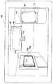
図1は、本明細書で開示する技術の一実施形態の概要について説明するための説明図である。図1を参照すると、実空間1内でユーザにより携帯されている端末装置100が示されている。<1. Overview>
FIG. 1 is an explanatory diagram for explaining an overview of an embodiment of the technology disclosed in this specification. Referring to FIG. 1, a
端末装置100は、ユーザとのインタラクションを伴うARアプリケーションをユーザに提供する装置である。端末装置100は、例えば、スマートフォン、PC(Personal Computer)、PDA(Personal Digital Assistant)、ゲーム端末又は携帯用音楽プレーヤなどであってよい。 The
実空間1は、ARアプリケーションが利用され得る空間の一例である。実空間1内には、物体12a、12b及び12cが存在する。物体12aは、案内用の看板である。物体12aには、シンボルマーク13aが付されている。物体12bは、情報表示用の掲示板である。物体12cは、広告用のポスターである。端末装置100は、このような実空間1を撮像した画像を入力画像として取得する。そして、端末装置100は、入力画像に映る物体の認識結果に基づいて、ARのための仮想オブジェクトを入力画像に重畳する。仮想オブジェクトを通じてユーザに呈示される情報は、ナビゲーション情報、広告情報、店舗情報、ニュース、天気予報又は列車の運行情報など、任意の情報であってよい。ユーザは、端末装置100の画面上に表示される仮想オブジェクトを操作し、ARアプリケーションをインタラクティブに利用する。 The
図1には示していないが、実空間1には、仮想オブジェクト又は仮想オブジェクトを通じてユーザに呈示すべき情報についてのデータベースを有するデータサーバが設けられてもよい。端末装置100は、例えば無線接続によってデータサーバと通信し、端末装置100の所在位置と関連付けられる最新のデータを当該データサーバからダウンロードしてもよい。 Although not shown in FIG. 1, the
<2.一実施形態に係る端末装置の構成例>
[2−1.ハードウェア構成]
図2は、本実施形態に係る端末装置100のハードウェア構成の一例を示すブロック図である。図2を参照すると、端末装置100は、撮像部102、センサ部104、入力部106、記憶部108、表示部112、通信部114、バス118及び制御部120を備える。<2. Configuration Example of Terminal Device According to One Embodiment>
[2-1. Hardware configuration]
FIG. 2 is a block diagram illustrating an example of a hardware configuration of the
(撮像部)
撮像部102は、画像を撮像するカメラモジュールである。撮像部102は、CCD(Charge Coupled Device)又はCMOS(Complementary Metal Oxide Semiconductor)などの撮像素子を用いて実空間を撮像し、撮像画像を生成する。撮像部102は、映像入力のための撮像回路と静止画入力のための撮像回路の双方又はいずれか一方のみを有していてもよい。(Imaging part)
The
(センサ部)
センサ部104は、端末装置100の位置及び姿勢の認識を支援し、又は端末装置100への一部のユーザ入力を検出するセンサ群である。例えば、センサ部104は、GPS(Global Positioning System)信号を受信して端末装置100の緯度、経度及び高度を測定するGPSセンサを含んでもよい。また、センサ部104は、無線アクセスポイントから受信される無線信号の強度に基づいて端末装置100の位置を測定する測位センサを含んでもよい。また、センサ部104は、端末装置100の3軸加速度を測定する加速度センサ又は傾き角を測定するジャイロセンサなどのモーションセンサを含んでもよい。(Sensor part)
The
(入力部)
入力部106は、ユーザが端末装置100を操作し又は端末装置100へ情報を入力するために使用される入力デバイスである。入力部106は、典型的には、表示部112の画面上へのユーザによるタッチを検出するタッチセンサを含む。その代わりに(又はそれに加えて)、入力部106は、マウス若しくはタッチパッドなどのポインティングデバイス、画像に映るユーザのジェスチャを認識するジェスチャ認識モジュール、又はHMD(Head Mounted Display)を装着したユーザの視線方向を検出する視線検出モジュールを含んでもよい。さらに、入力部106は、キーボード、キーパッド、ボタン又はスイッチなどのその他の種類の入力デバイスを含んでもよい。(Input section)
The
(記憶部)
記憶部108は、半導体メモリ又はハードディスクなどの記憶媒体により構成され、端末装置100による処理のためのプログラム及びデータを記憶する。記憶部108により記憶されるデータには、例えば、撮像部102により生成される画像データ及びセンサ部104により生成されるセンサデータが含まれ得る。また、記憶部108により記憶されるデータには、例えば、端末装置100による画像認識の際に用いられる特徴量データ及び仮想オブジェクトを定義するオブジェクトデータなども含まれ得る。(Memory part)
The
(表示部)
表示部112は、LCD(Liquid Crystal Display)、OLED(Organic light-Emitting Diode)又はCRT(Cathode Ray Tube)などにより構成される表示モジュールである。表示部112は、例えば、撮像部102により撮像される画像、又は制御部120により実現されるARアプリケーションの画像を画面上に表示する。表示部112は、ユーザにより把持される端末装置100の画面であってもよく、又はユーザにより装着されるシースルー型若しくは非シースルー型のHMDであってもよい。(Display section)
The
(通信部)
通信部114は、端末装置100による他の装置(例えば、上述したデータサーバ)との間の通信を仲介する通信インタフェースである。通信部114は、任意の無線通信プロトコル又は有線通信プロトコルをサポートし、他の装置との間の通信接続を確立する。(Communication Department)
The
(バス)
バス118は、撮像部102、センサ部104、入力部106、記憶部108、表示部112、通信部114及び制御部120を相互に接続する。(bus)
The
(制御部)
制御部120は、CPU(Central Processing Unit)又はDSP(Digital Signal Processor)などのプロセッサに相当する。制御部120は、記憶部108又は他の記憶媒体に記憶されるプログラムを実行することにより、後に説明する端末装置100の様々な機能を動作させる。(Control part)
The
[2−2.機能構成]
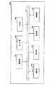
図3は、図2に示した端末装置100の記憶部108及び制御部120により実現される論理的機能の構成の一例を示すブロック図である。図3を参照すると、端末装置100は、画像取得部110、フレームメモリ112、画像認識部130、特徴量データベース(DB)132、拘束領域設定部140、検出部150、操作制御部160、データ取得部170、オブジェクトDB172及び表示制御部190を含む。[2-2. Functional configuration]
FIG. 3 is a block diagram illustrating an example of a configuration of logical functions realized by the
(1)画像取得部
画像取得部110は、実空間を映した画像を入力画像として取得する。本実施形態において、画像取得部110は、リアルタイムモード及びスナップショットモードという2つの入力モードをサポートする。リアルタイムモードでは、画像取得部110は、撮像部102からの映像入力の最新のフレームを入力画像として順次取得する。スナップショットモードでは、画像取得部110は、まず、スナップショットモードの開始時に、撮像部102により撮像されるスナップショットをフレームメモリ112に記憶させる。撮像部102が映像入力のための撮像回路と静止画入力のための撮像回路とを有する場合には、スナップショットは、静止画入力のための撮像回路によって撮像される画像であってもよい。その後、画像取得部110は、フレームメモリ112により記憶されたスナップショットを継続的に入力画像として取得する。リアルタイムモードとスナップショットモードとの間の切り替えは、入力部106を介する所定のユーザ入力によって行われてよい。画像取得部110は、このように取得される入力画像を画像認識部130へ出力する。(1) Image acquisition unit The
(2)画像認識部
画像認識部130は、画像取得部110から入力される入力画像にどの物体が映っているかを認識する。また、画像認識部130は、入力画像に映っている物体の実空間内での位置及び姿勢を認識する。より具体的には、例えば、画像認識部130は、入力画像の特徴量を抽出する。そして、画像認識部130は、抽出した特徴量を、特徴量DB132に予め記憶されている既知の様々な物体画像の特徴量と照合することにより、入力画像に映る物体を識別し、当該物体の位置及び姿勢を認識する。画像認識部130が用いる特徴量抽出アルゴリズムは、例えば、“Fast Keypoint Recognition using Random Ferns”(Mustafa Oezuysal,IEEE Transactions on Pattern Analysis and Machine Intelligence, Vol.32, Nr.3, pp.448-461, March 2010)に記載されたRandom Ferns法、又は“SURF: Speeded Up Robust Features”(H.Bay, A.Ess, T.Tuytelaars and L.V.Gool, Computer Vision and Image Understanding(CVIU), Vol.110, No.3, pp.346--359, 2008)に記載されたSURF法などであってよい。その代わりに、画像認識部130は、既知の図形若しくは記号(例えば、図1に示した物体12aのシンボルマーク13aのような、案内看板に画一的に付されるマーク)、物体に付される人工マーカ(例えば、バーコード若しくはQRコード)又は自然マーカなどを用いて入力画像に映る物体を識別し、入力画像内での当該物体のサイズ及び形状からその位置及び姿勢を認識してもよい。(2) Image Recognition Unit The
図4は、画像認識部130による画像認識の結果の一例について説明するための説明図である。図4を参照すると、画像認識部130へ入力される一例としての入力画像Im1が示されている。画像認識部130による画像認識の結果として、入力画像Im1に映る物体12aの位置Xa及び姿勢Wa、物体12bの位置Xb及び姿勢Wb、並びに物体12cの位置Xc及び姿勢Wcが認識されている。各物体の位置Xは、3次元のグローバル座標系(x,y,z)によって、各物体の基準点の位置として与えられ得る。グローバル座標系は、例えば、端末装置100の位置を原点とする相対的な位置座標を表す座標系であってもよい。その代わりに、グローバル座標系は、実空間内に固定的に定義される座標系であってもよい。各物体の姿勢Wは、グローバル座標系を基準とした各物体の回転を表す回転行列又はクォータニオン(四元数)として与えられ得る。なお、本明細書では、説明の簡明さのために各物体の位置X及び姿勢Wを別個の変量として説明する。しかしながら、各物体の位置X及び姿勢Wは、グローバル座標系と各物体のモデル座標系との間の変換を表す4行4列の1つの同次変換行列によって統合的に表現されてもよい。その場合には、各物体の位置X及び姿勢Wは、1つの同次変換行列から必要に応じて抽出され用いられ得る。画像認識部130は、このように認識した入力画像に映る各物体の識別子、位置及び姿勢を、拘束領域設定部140、データ取得部170及び表示制御部190へ出力する。FIG. 4 is an explanatory diagram for explaining an example of a result of image recognition by the
(3)拘束領域設定部
拘束領域設定部140は、画像認識部130により認識される物体の姿勢に基づいて、入力画像に映る実空間内に、ユーザ入力に応じて操作される仮想オブジェクトの動きを拘束する拘束領域を設定する。拘束領域は、線又は面によって表現される高々2次元の領域である。拘束領域設定部140は、典型的には、操作可能な仮想オブジェクトと関連付けられる物体ごとに拘束領域を設定し得る。拘束領域は、例えば、入力画像内で認識される物体の表面に沿って設定されてもよい。この場合、仮想オブジェクトが略平面状のオブジェクトであれば、当該仮想オブジェクトは、関連付けられる物体の表面に沿って配置され、その表面に沿って移動、拡大、縮小又はスクロールし得る。拘束領域は、例えば、入力画像内で認識される物体との間に所定のオフセットを有する位置に設定されてもよい。なお、略平面状のオブジェクトとは、その形状が必ずしも完全な平面状に限定されず、多少の凹凸や厚みの変化などを有する平面状のオブジェクトを含むものとする。(3) Restricted Area Setting Unit The restricted
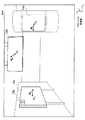
図5Aは、本実施形態において拘束領域設定部140により実空間1内に設定される拘束領域の第1の例を示す説明図である。図5Aを参照すると、物体12aと関連付けて設定される一例としての拘束領域14aが示されている。拘束領域14aは、物体12aの表面に沿って設定される平面状の領域である。物体12aと関連付けられる仮想オブジェクトの動きは、このような拘束領域14aにより拘束される(例えば、拘束領域14aから離れて移動しない)。 FIG. 5A is an explanatory diagram illustrating a first example of a restricted area set in the
図5Bは、本実施形態において拘束領域設定部140により実空間1内に設定される拘束領域の第2の例を示す説明図である。図5Bを参照すると、物体12bと関連付けて設定される一例としての拘束領域14bが示されている。拘束領域14bは、物体12bの中央を通り、物体12bの上下方向に沿って設定される線状の領域である。物体12bと関連付けられる仮想オブジェクトの動きは、このような拘束領域14bにより拘束される(例えば、拘束領域14bに沿った上下方向にのみスクロール可能である)。 FIG. 5B is an explanatory diagram illustrating a second example of the constraint area set in the
図5Cは、本実施形態において拘束領域設定部140により実空間1内に設定される拘束領域の第3の例を示す説明図である。図5Cを参照すると、物体12cと関連付けて設定される一例としての拘束領域14cが示されている。拘束領域14cは、物体12cの表面に沿って設定される曲面状の領域である。このように、拘束領域の形状は、平面状又は直線状に限定されず、曲面状、多面的な形状、曲線状又は折れ線状などであってもよい。 FIG. 5C is an explanatory diagram illustrating a third example of the constraint area set in the
(4)検出部
検出部150は、ユーザ入力を検出し、ユーザ入力情報を操作制御部160へ出力する。検出部150により検出されるユーザ入力は、例えば、図2に示した入力部106のタッチセンサへの様々なタッチ入力(例えば、タッチ、タップ、ダブルタップ、ドラッグ、フリック、ピンチイン及びピンチアウトなど)を含み得る。また、検出部150により検出されるユーザ入力は、例えば、図2に示したセンサ部104のセンサ群により測定される端末装置100の動き(例えば、傾き又は揺れなど)をも含み得る。(4) Detection Unit The
(5)操作制御部
操作制御部160は、端末装置100の画面上に表示される仮想オブジェクトのユーザによる操作を制御する。より具体的には、操作制御部160は、検出部150によりユーザ入力が検出されると、まず、操作対象の仮想オブジェクトを特定する。次に、操作制御部160は、特定した仮想オブジェクトの動きを、ユーザ入力に応じて、当該仮想オブジェクトに対応する物体と関連付けられる拘束領域内で決定する。そして、操作制御部160は、決定した仮想オブジェクトの動きを表示制御部190に通知して、仮想オブジェクトの画面上での配置、サイズ又はスクロール位置などを表示制御部190により変更させる。それにより、仮想オブジェクトの移動、拡大、縮小又はスクロールなどといった動きが可視化される。(5) Operation Control Unit The
(5−1)タッチセンサでのユーザ入力
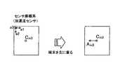
図6及び図7は、操作制御部160により制御される、タッチセンサを介する仮想オブジェクトの操作について説明するための説明図である。図6を参照すると、実空間内に設定される平面状の拘束領域14、及び撮像装置の撮像面103が示されている。拘束領域14の位置X0及び姿勢W0は、拘束領域14と関連付けられる物体の位置及び姿勢と等しくてもよく、又は当該物体の位置及び姿勢との間で所定のオフセットを有していてもよい。タッチセンサへのユーザ入力の入力位置Cinは、撮像面103上のカメラ座標系(u,v,1)により与えられる。操作制御部160は、例えば、以下のようなピンホールモデルに従って、入力位置Cinに対応する拘束領域14内の位置Xinを算出し得る。(5-1) User Input with Touch Sensor FIGS. 6 and 7 are explanatory diagrams for explaining the operation of the virtual object via the touch sensor, which is controlled by the

式(1)において、C0は拘束領域14の基準位置X0に対応する撮像面上の位置、Aはカメラ内部パラメータ、λは正規化のためのパラメータである。カメラ内部パラメータAは、撮像部102の特性に応じて、予め次式のように与えられる。In Expression (1), C0 is a position on the imaging surface corresponding to the reference position X0 of the constrained
ここで、fは焦点距離、θは画像軸の直交性(理想値は90°)、kuは撮像面の縦軸のスケール(実空間の座標系からカメラ座標系へのスケール変化率)、kvは撮像面の横軸のスケール、(uo,vo)は撮像面の中心位置である。Here, f is the focal length, θ is the orthogonality of the image axis (ideal value is 90 °),ku is the scale of the vertical axis of the imaging surface (scale change rate from the real space coordinate system to the camera coordinate system), kv is the scale of the horizontal axis of the imaging surface, and (uo , vo ) is the center position of the imaging surface.
例えばドラッグのようなベクトルを指定するユーザ入力については、操作制御部160は、ベクトルの始点及び終点に対応する2つの入力位置Cin1及びCin2に基づいて、次式のように、拘束領域14内の仮想オブジェクトの動きベクトルVinを決定し得る:For example, for a user input specifying a vector such as a drag, the
式(3)において、Xin1及びXin2は、入力位置Cin1及びCin2にそれぞれ対応する拘束領域内の位置である。なお、拘束領域が曲面状又は多面的な形状である場合にも、操作制御部160は、同様に、ユーザ入力の入力位置を拘束領域に投影することにより、各入力位置に対応する拘束領域内の位置を決定することができる。また、拘束領域が線状である場合には、操作制御部160は、ユーザ入力の入力位置を1次元の当該拘束領域に投影する。In Expression (3), Xin1 and Xin2 are positions in the constraint region corresponding to the input positions Cin1 and Cin2 , respectively. Even in the case where the constraint area is a curved surface or a multifaceted shape, the
上述した式(3)のようにユーザ入力の入力位置を拘束領域に投影して動きベクトルVinを決定する際、拘束領域14と端末装置100との間の距離が大きい場合には、ユーザ入力に対して動きベクトルVinの大きさが過度に大きくなり得る。そこで、操作制御部160は、端末装置100と拘束領域14との間の距離に応じて、画面上の入力ベクトルの大きさに対する動きベクトルVinの大きさの割合を変化させてもよい。それにより、仮想オブジェクトの動きをユーザが微調整することがより容易となる。入力ベクトルの大きさとは例えば画面上でのドラッグ量、動きベクトルVinの大きさとは例えば仮想オブジェクトの動きの量にそれぞれ対応する。When determining the motion vector Vin by projecting restraining area an input position of the user input as the equation (3), when the distance between the restraining
例えば、図7の例において、操作制御部160は、入力位置Cin1からCin2へのドラッグが検出された場合に、入力位置Cin1及びCin2にそれぞれ対応する拘束領域14内の位置Xin1及びXin2を算出する。ここで、端末装置100と拘束領域14との間の距離Dは、所定の閾値Thを上回る。そこで、操作制御部160は、位置Xin1からXin2への動きベクトルVinに係数k(k<1)を乗じることにより、仮想オブジェクトの修正後の動きベクトルV´inを算出する。係数kは、例えば、端末装置100と拘束領域14との間の距離が増加するにつれて減少するような係数であってもよい。For example, in the example of FIG. 7, when the drag from the input position Cin1 to Cin2 is detected, the
(5−2)モーションセンサでのユーザ入力
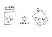
図8〜図11は、操作制御部160により制御される、モーションセンサを介する仮想オブジェクトの操作について説明するための説明図である。(5-2) User Input with Motion Sensor FIGS. 8 to 11 are explanatory diagrams for explaining the operation of the virtual object via the motion sensor, which is controlled by the
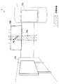
図8を参照すると、端末装置100の加速度センサのセンサ座標系(a1,a2,a3)が示されている。一例として、a1軸は端末装置100の画面の水平方向、a2軸は当該画面の垂直方向、a3軸は当該画面の奥行き方向に沿った軸である。ここで、例えばユーザが入力位置Cin3をタッチしながら端末装置100の画面の水平方向の左に向けて端末装置100を振ったものとする。すると、加速度センサからのセンサデータにおいてa1軸成分に大きな値を有する加速度ベクトルAin3が生じる。操作制御部160は、このようなセンサデータが検出部150から入力されると、加速度ベクトルAin3に対応する拘束領域内の動きベクトルを算出する。図9の例では、加速度ベクトルAin3に対応する動きベクトルVin3が、加速度ベクトルAin3を拘束領域14の平面に投影することにより算出される様子が示されている。Referring to FIG. 8, a sensor coordinate system (a1, a2, a3) of the acceleration sensor of the
図10を参照すると、端末装置100のジャイロセンサにより測定される傾き角についてのセンサ座標系(w1,w2,w3)が示されている。ここで、例えばユーザが入力位置Cin4をタッチしながら端末装置100の画面に垂直な軸の周り(w1方向)に端末装置100を傾けたものとする。すると、ジャイロセンサからのセンサデータにおいてw1軸成分の値が増加する。操作制御部160は、このようなセンサデータが検出部150から入力されると、端末装置100に重力Gの水平方向成分Gin4が加わっていることを認識する。そこで、操作制御部160は、重力Gの水平方向成分Gin4に対応する拘束領域内の動きベクトルを算出する。図11の例では、水平方向成分Gin4に対応する動きベクトルVin4が、水平方向成分Gin4を拘束領域14の平面に投影することにより算出される様子が示されている。Referring to FIG. 10, a sensor coordinate system (w1, w2, w3) for the tilt angle measured by the gyro sensor of the
なお、ここでは主にタッチセンサ又はモーションセンサを介するユーザ入力について説明した。しかしながら、操作制御部160は、例えばユーザの所定のジェスチャなど、上述した例とは異なる種類のユーザ入力に応じて、仮想オブジェクトの操作を制御してもよい。ユーザのジェスチャは、ユーザに向けられる(入力画像を撮像する装置と別の)撮像装置によって撮像される画像から認識されてもよい。その代わりに、ユーザのジェスチャは、例えばHMDを用いる場合のように、ユーザの視線方向に向けられる撮像装置によって撮像される画像から認識されてもよい。 In addition, the user input mainly via a touch sensor or a motion sensor was demonstrated here. However, the
(5−3)操作対象の特定
操作制御部160は、操作対象の仮想オブジェクトをユーザ入力の入力位置に応じて決定してもよい。例えば、タッチセンサ上のタッチ又はドラッグの開始により操作対象の仮想オブジェクトが選択される場合には、入力位置とカメラの焦点位置とを結ぶ投影線上に判定域が存在する仮想オブジェクトが、操作対象として決定される。本明細書において、判定域とは、仮想オブジェクトと関連付けられ、ユーザにより指定されることで当該仮想オブジェクトが操作対象であると判定される画面上の領域をいう。投影線上に複数の仮想オブジェクトの判定域が存在する場合には、端末装置100の最も近くに位置する仮想オブジェクトが操作対象とされてよい。仮想オブジェクトの判定域は、必ずしも仮想オブジェクトが表示されている領域と一致していなくてもよい。また、操作制御部160は、判定域によらず、端末装置100の画面上で最も大きく表示されている仮想オブジェクト、端末装置100の最も近くに位置する仮想オブジェクト、又は端末装置100の画面に正対している仮想オブジェクトなどを操作対象として特定してもよい。(5-3) Specifying Operation Target The
(5−4)仮想オブジェクトの動きの例
本実施形態において、仮想オブジェクトの動きは、ユーザ入力の種類と、ユーザ入力に応じて決定される拘束領域内の位置又は動きベクトルとに応じて決定され得る。(5-4) Example of Movement of Virtual Object In the present embodiment, the movement of the virtual object is determined according to the type of user input and the position or motion vector in the constraint area determined according to the user input. obtain.
例えば、仮想オブジェクトが所定の情報を表示する略平面状のオブジェクトであるものとする。所定の情報とは、例えば、ナビゲーション情報、広告情報、店舗情報、ニュース、天気予報又は列車の運行情報などであってよい。この場合、操作制御部160は、例えば、上記略平面状の仮想オブジェクトがユーザによりドラッグされると、ドラッグ方向に応じて決定される拘束領域内の動きベクトルの方向に沿って、表示されている情報を3次元空間内でスクロールさせる。スクロール量は、動きベクトルの大きさに相当し得る。また、操作制御部160は、上記略平面状の仮想オブジェクトがユーザによりピンチイン又はピンチアウトされると、ピンチイン又はピンチアウトに対応する拘束領域内の動きベクトルの大きさに応じて、表示されている情報を縮小し又は拡大してもよい。また、操作制御部160は、上記略平面状の仮想オブジェクトが特定されている状態で画面上のいずれかの位置がタップされると、タップ位置に対応する拘束領域内の位置に、当該仮想オブジェクトを移動させてもよい。また、操作制御部160は、上記略平面状の仮想オブジェクトが特定されている状態で端末装置100に加速度が加えられると、発生した加速度ベクトルに対応する拘束領域内の動きベクトルの方向に沿って、表示されている情報を3次元空間内でスクロールさせてもよい。このような仮想オブジェクトの動きのいくつかの例について、後に図面を用いてさらに説明する。 For example, it is assumed that the virtual object is a substantially planar object that displays predetermined information. The predetermined information may be, for example, navigation information, advertisement information, store information, news, weather forecast, or train operation information. In this case, for example, when the substantially planar virtual object is dragged by the user, the
なお、上述した例に限定されず、仮想オブジェクトは、例えば立体的なオブジェクト(ナビゲーション用の案内板、広告の対象である商品のポリゴンなど)であってもよい。その場合にも、仮想オブジェクトの配置又はサイズなどが、ユーザ入力の種類と、ユーザ入力に応じて決定される拘束領域内の位置又は動きベクトルとに応じて決定され得る。 Note that the virtual object is not limited to the example described above, and may be, for example, a three-dimensional object (a navigation guide plate, a polygon of a product to be advertised). Even in this case, the arrangement or size of the virtual object can be determined according to the type of user input and the position or motion vector in the constraint area determined according to the user input.
(6)データ取得部
データ取得部170は、表示制御部190により入力画像に重畳される仮想オブジェクトに関するデータを取得する。データ取得部170により取得されるデータは、仮想オブジェクトを定義するオブジェクトデータを含む。オブジェクトデータは、例えば、仮想オブジェクトの種類、関連付けられる物体の識別子、当該物体からの相対的な表示位置、及びユーザに呈示される情報の内容などを定義し得る。ユーザに呈示される情報の内容は、テキスト形式で与えられてもよく、又はイメージ形式で与えられてもよい。データ取得部170は、オブジェクトDB172により予め記憶されるオブジェクトデータを取得してもよい。その代わりに、データ取得部170は、実空間内に設置されるデータサーバから通信部114を介して最新のオブジェクトデータを取得してもよい。データサーバから提供されるオブジェクトデータは、例えば、センサ部104により測定される端末装置100の位置に応じて異なるデータであってもよい。データ取得部170は、このようなオブジェクトデータを表示制御部190へ出力する。(6) Data Acquisition Unit The
(7)表示制御部
表示制御部190は、入力画像に仮想オブジェクトを重畳することにより出力画像を生成する。より具体的には、例えば、表示制御部190には、画像認識部130により入力画像に映っていると認識された物体と関連付けられている仮想オブジェクトのオブジェクトデータが、データ取得部170から入力される。表示制御部190は、かかるオブジェクトデータに基づいて、仮想オブジェクトのオブジェクト画像を生成する。表示制御部190により生成されるオブジェクト画像は、典型的には、3次元の実空間内に仮想的に配置される仮想オブジェクトを(例えば上述したピンホールモデルに従って)端末装置100の撮像面に投影した画像である。実空間内での仮想オブジェクトの位置及び姿勢は、関連付けられる物体の位置及び姿勢、並びにオブジェクトデータでの定義に従って決定され得る。そして、表示制御部190は、生成した出力画像を表示部112へ出力することにより、ARアプリケーションの画像を表示する。(7) Display Control Unit The
また、表示制御部190は、仮想オブジェクトの状態(位置、姿勢、サイズ又はスクロール位置など)を、操作制御部160により決定される仮想オブジェクトの動きに応じて変更する。表示制御部190は、例えば、リアルタイムモードにおいては、画像取得部110により順次取得される各入力画像に、ユーザ入力に応じて時々刻々と状態が変化する仮想オブジェクトのオブジェクト画像を重畳する。それにより、リアルタイムで更新される出力画像において、仮想オブジェクトの動きが表現される。また、表示制御部190は、スナップショットモードにおいては、画像取得部110によりフレームメモリ112から取得される入力画像のスナップショットを複数のフレーム分複製し、複製されたスナップショットの各々に仮想オブジェクトの動きを表現するオブジェクト画像を重畳する。それにより、静止画のスナップショット上での仮想オブジェクトの動きが表現される。 In addition, the
また、表示制御部190は、仮想オブジェクトの拘束領域内での可動方向を表現する補助的なオブジェクトを、入力画像にさらに重畳してもよい。また、表示制御部190は、各仮想オブジェクトの判定域を表現する補助的なオブジェクトを、入力画像にさらに重畳してもよい。表示制御部190により表示される補助的なオブジェクトの例について、後に図面を用いて説明する。 In addition, the
<3.処理の流れ>
図12は、本実施形態に係る端末装置100によるオブジェクト制御処理の流れの一例を示すフローチャートである。<3. Process flow>
FIG. 12 is a flowchart illustrating an example of the flow of object control processing by the
図12を参照すると、まず、画像取得部110は、撮像部102により撮像され又はフレームメモリ112により記憶されている入力画像を取得する(ステップS102)。次に、画像認識部130は、取得された入力画像に映る物体、並びに当該物体の位置及び姿勢を認識する(ステップS104)。次に、データ取得部170は、認識された物体に関するオブジェクトデータをオブジェクトDB172又は外部のデータサーバから取得する(ステップS106)。Referring to FIG. 12, first, the
次に、操作制御部160は、仮想オブジェクトを操作するためのユーザ入力が検出部150により検出されたか否かを判定する(ステップS108)。ここで、検出部150によりユーザ入力が検出された場合には、処理はステップS110へ進む。一方、ユーザ入力が検出されていない場合には、処理はステップS118へ進む。 Next, the
ユーザ入力が検出された場合には、操作制御部160は、当該ユーザ入力の入力位置、仮想オブジェクトの画面上での大きさ又は仮想オブジェクトと端末装置100との距離などの基準に基づいて、操作対象の仮想オブジェクトを特定する(ステップS110)。次に、操作制御部160は、特定した仮想オブジェクトと関連付けて拘束領域設定部140により設定される拘束領域を認識する(ステップS112)。次に、操作制御部160は、ユーザ入力の入力位置又は入力ベクトルに対応する拘束領域内の3次元的な位置又はベクトルを算出する(ステップS114)。そして、操作制御部160は、算出した拘束領域内の位置又はベクトルとユーザ入力の種類とに基づいて、操作対象の仮想オブジェクトの動きを決定する(ステップS116)。 When a user input is detected, the
ステップS118では、表示制御部190は、実空間内に仮想的に配置される仮想オブジェクトを撮像面に投影することにより、仮想オブジェクトのオブジェクト画像を生成し、生成したオブジェクト画像を入力画像に重畳する(ステップS118)。ここでの仮想オブジェクトの状態は、当該仮想オブジェクトが操作されていない場合には、初期状態である(初期状態は、オブジェクトデータにより定義され得る)。一方、仮想オブジェクトの状態は、当該仮想オブジェクトが操作されている場合には、操作制御部160により決定される動きに従って変更された状態である。次に、表示制御部190は、各仮想オブジェクトの拘束領域内での可動方向を表現する補助的なオブジェクトを、入力画像にさらに重畳する(ステップS120)。そして、仮想オブジェクト及び補助的なオブジェクトが重畳された出力画像が、画面上に表示される(ステップS122)。 In step S118, the
図12に示したオブジェクト制御処理は、リアルタイムモードにおいては、撮像部102により撮像される各フレームについて繰り返され得る。また、スナップショットモードにおいては、上記オブジェクト制御処理は、画像取得部110によりフレームメモリ112から取得されるスナップショットを入力画像として用いて行われ得る。スナップショットモードでは、1回(あるいは1ストローク)のユーザ入力についてステップS118〜S122の処理が複数回繰り返して行われることにより、仮想オブジェクトの動きがアニメーションとして表現され得る。 The object control process shown in FIG. 12 can be repeated for each frame imaged by the
図13は、図12のステップS102における画像取得処理の詳細な流れの一例を示すフローチャートである。 FIG. 13 is a flowchart showing an example of a detailed flow of the image acquisition process in step S102 of FIG.
図13を参照すると、画像取得部110は、まず、現在のモードがスナップショットモードかリアルタイムモードかを判定する(ステップS132)。ここで、現在のモードがリアルタイムモードである場合には、画像取得部110は、撮像部102から最新の入力画像を取得する(ステップS134)。一方、現在のモードがスナップショットモードである場合には、画像取得部110は、スナップショットを新たに取得すべきか否かを判定する(ステップS136)。例えば、スナップショットモードが新たに開始される場合、又はスナップショットのリフレッシュがユーザにより指示された場合には、画像取得部110は、スナップショットを新たに取得すべきであると判定する。ここで、スナップショットを新たに取得すべきであると判定された場合には、画像取得部110は、撮像部102から最新の入力画像を取得し(ステップS138)、取得した入力画像をスナップショットとしてフレームメモリ112に記憶させる(ステップS140)。一方、スナップショットを新たに取得しなくてよいと判定された場合には、画像取得部110は、フレームメモリ112に記憶されているスナップショットを入力画像として取得する(ステップS142)。 Referring to FIG. 13, the
<4.操作シナリオ>
次に、上述した端末装置100を用いて実現され得る仮想オブジェクトの操作の例示的な3つのシナリオについて説明する。<4. Operation scenario>
Next, three exemplary scenarios of virtual object operations that can be realized using the
[4−1.第1のシナリオ]
図14A及び図14Bは、仮想オブジェクトの操作の第1のシナリオについて説明するための説明図である。[4-1. First scenario]
FIG. 14A and FIG. 14B are explanatory diagrams for explaining a first scenario of the virtual object operation.
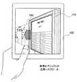
図14Aを参照すると、実空間に存在する物体12dが映っている画像が、端末装置100の画面に表示されている。物体12dは、駅に設置される案内用の看板である。端末装置100のデータ取得部170は、入力画像に物体12dが映っていることが画像認識部130により認識されると、物体12dと関連付けられている仮想オブジェクト16dのオブジェクトデータを取得する。仮想オブジェクト16dは、例えば、駅の見取り図、出口案内、及び時刻表などを表示する略平面状のオブジェクトである。図14Aの例では、仮想オブジェクト16dの一部のみが物体12dに重畳されている。仮想オブジェクト16dの拘束領域は、例えば、物体12dの表面に沿った領域である。拘束領域設定部140は、物体12dの位置及び姿勢に基づいて、仮想オブジェクト16dの拘束領域を設定する。そして、例えば、ユーザが端末装置100の画面上で物体12dを左上方向(図中の矢印参照)に向けてドラッグしたものとする。 Referring to FIG. 14A, an image showing an
図14Bを参照すると、上述したドラッグの結果、仮想オブジェクト16dが左奥の方向へスクロールしている。そして、ドラッグの前には表示されていなかった仮想オブジェクト16dの時刻表の部分が、物体12dに重畳されている。 Referring to FIG. 14B, as a result of the dragging described above, the
[4−2.第2のシナリオ]
図15A及び図15Bは、仮想オブジェクトの操作の第2のシナリオについて説明するための説明図である。[4-2. Second scenario]
FIG. 15A and FIG. 15B are explanatory diagrams for describing the second scenario of the virtual object operation.
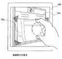
図15Aを参照すると、実空間に存在する物体12eが映っている画像が、端末装置100の画面に表示されている。物体12eは、地図が描かれた案内板である。端末装置100のデータ取得部170は、入力画像に物体12eが映っていることが画像認識部130により認識されると、物体12eと関連付けられている仮想オブジェクト16eのオブジェクトデータを取得する。仮想オブジェクト16eは、例えば、地図情報を表示する略平面状のオブジェクトである。地図情報の初期の表示内容は、物体12eに実際に描かれている地図と同様の内容であってよい。仮想オブジェクト16eの拘束領域は、例えば、物体12eの表面に沿った領域である。拘束領域設定部140は、物体12eの位置及び姿勢に基づいて、仮想オブジェクト16eの拘束領域を設定する。そして、例えば、ユーザが端末装置100の画面上の地図部分でピンチアウトを行ったものとする。 Referring to FIG. 15A, an image showing an
図15Bを参照すると、上述したピンチアウトの結果、仮想オブジェクト16eにより表示されている地図が拡大している。但し、当該地図は、単純に画面内で拡大されているのではなく、物体12eの姿勢に応じて物体12eの表面に沿った平面内で拡大されている。 Referring to FIG. 15B, as a result of the pinch out described above, the map displayed by the
なお、操作制御部160は、例えば、地図部分においてピンチイン又はピンチアウトが行われた場合には拘束領域内で地図を縮小又は拡大させ、地図部分以外の部分においてピンチイン又はピンチアウトが行われた場合には画像全体を撮像面と平行に縮小又は拡大させてもよい。 The
[4−3.第3のシナリオ]
図16Aを参照すると、図14Bの例と同様、端末装置100の画面に表示された物体12d及び仮想オブジェクト16dが再び示されている。ここで、例えば、ユーザが端末装置100の本体を右へ傾けたものとする。[4-3. Third scenario]
Referring to FIG. 16A, similarly to the example of FIG. 14B, the
図16Bを参照すると、端末装置100が傾けられた結果、仮想オブジェクト16dが右手前の方向へスクロールしている。そして、図16Bの例において物体12dに重畳されていた仮想オブジェクト16dの時刻表の部分が画面外へ消え、仮想オブジェクト16dの出口案内の部分が物体12dに重畳されている。 Referring to FIG. 16B, as a result of the
これらシナリオの例のように、本実施形態では、仮想オブジェクトは、ユーザ入力に応じて単純に画面内で上下左右に動くのではなく、関連付けられている物体の姿勢に応じてあたかも3次元の実空間内で動くかのように操作され得る。それにより、ユーザがまさに拡張された実空間内にいるという感覚、即ちAR空間へのユーザの没入感を損なうことなく、ARの仮想オブジェクトをユーザに操作させることができる。 As in these scenario examples, in this embodiment, the virtual object does not simply move up and down and left and right within the screen in response to user input, but as if it is a three-dimensional real object according to the posture of the associated object. It can be manipulated as if it were moving in space. Thereby, the user can operate the virtual object of the AR without impairing the feeling that the user is in the expanded real space, that is, the user's immersion in the AR space.
なお、ここでは、入力画像に映る物体の表面に仮想オブジェクトが重畳される例について主に説明したが、仮想オブジェクトは、物体の表面から離れた位置に重畳されてもよい。また、表示制御部190は、入力画像のテクスチャなどに基づいて仮想オブジェクトを重畳すべき面を認識してもよい。例えば、建物の壁面、通路の床面など、入力画像内で一様なテクスチャを有する平面が、仮想オブジェクトを重畳すべき面として認識されてもよい。 Although an example in which the virtual object is superimposed on the surface of the object shown in the input image has been mainly described here, the virtual object may be superimposed at a position away from the surface of the object. Further, the
[4−4.補助的なオブジェクトの表示]
図17は、仮想オブジェクトの可動方向を表現する補助オブジェクトについて説明するための説明図である。[4-4. Show auxiliary objects]
FIG. 17 is an explanatory diagram for explaining an auxiliary object that expresses a moving direction of a virtual object.
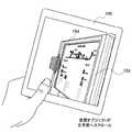
図17を参照すると、端末装置100の画面上に3つの物体12a、12b及び12cが表示されている。物体12aには、仮想オブジェクト16aが重畳されている。仮想オブジェクト16aの左端には、仮想オブジェクト16aが左手前方向へスクロール可能であることを表現する補助オブジェクト17a(シャドウグラデーション)が表示されている。また、物体12bには、仮想オブジェクト16bが重畳されている。仮想オブジェクト16bの下方には、仮想オブジェクト16bが下方向へスクロール可能であることを表現する補助オブジェクト17b(矢印)が表示されている。物体12cには、仮想オブジェクト16cが重畳されている。仮想オブジェクト16cの四隅には、仮想オブジェクト16cが物体12cの表面に沿って拡大可能であることを表現する補助オブジェクト17c(三角形のツメ)が表示されている。 Referring to FIG. 17, three
このように、仮想オブジェクトの可動方向を表現する補助オブジェクトを仮想オブジェクトと関連付けて表示することで、仮想オブジェクトをどのように操作し得るかをユーザに容易に把握させることができる。 In this way, by displaying the auxiliary object representing the movable direction of the virtual object in association with the virtual object, the user can easily understand how the virtual object can be operated.
また、図17の例において、仮想オブジェクト16aは、端末装置100の最も近くに位置する仮想オブジェクトである。仮想オブジェクト16aには、太線枠である補助オブジェクト18aが重畳されている。補助オブジェクト18aは、いわゆるフォーカスを表現するオブジェクトである。複数の仮想オブジェクトのいずれも特にユーザに指定されることなく何らかのユーザ入力が行われた場合には、このようにフォーカスが当てられている仮想オブジェクトが操作制御部160により操作対象として特定され得る。
In the example of FIG. 17, the
<5.まとめ>
ここまで、図1〜図17を用いて、一実施形態に係る端末装置100について詳細に説明した。本実施形態によれば、ユーザ入力に応じて操作されるARの仮想オブジェクトの動きが、入力画像内で認識される物体の姿勢に基づいて実空間内に設定される拘束領域内で決定される。従って、仮想オブジェクトは、実世界の状況と無関係に操作されるのではなく、実世界に存在する物体の姿勢に即して3次元的に動くかのように操作され得る。それにより、仮想オブジェクトの操作に際して、AR空間へのユーザの没入感を損なうことなく、自然な操作及び表示を実現することができる。<5. Summary>
So far, the
また、本実施形態によれば、上記拘束領域は、入力画像内で認識される物体の表面に沿って設定され得る。そして、仮想オブジェクトは、所定の情報を表示する略平面状のオブジェクトであって、上記物体の表面に沿って移動、拡大、縮小又はスクロールされ得る。従って、ユーザは、あたかも実世界の物体上に表された情報を直接操作するかのような現実感を持ちながら、より豊富に与えられる情報を自在に閲覧することができる。 Further, according to the present embodiment, the constraint area can be set along the surface of the object recognized in the input image. The virtual object is a substantially planar object that displays predetermined information, and can be moved, enlarged, reduced, or scrolled along the surface of the object. Therefore, the user can freely browse the information given more abundantly while having a sense of reality as if the information represented on the object in the real world is directly manipulated.
なお、本明細書において説明した端末装置100による処理は、ソフトウェア、ハードウェア、及びソフトウェアとハードウェアとの組合せのいずれを用いて実現されてもよい。ソフトウェアを構成するプログラムは、例えば、各装置の内部又は外部に設けられる記憶媒体に予め格納される。そして、各プログラムは、例えば、実行時にRAM(Random Access Memory)に読み込まれ、CPU(Central Processing Unit)などのプロセッサにより実行される。 Note that the processing by the
以上、添付図面を参照しながら本開示の好適な実施形態について詳細に説明したが、本技術はかかる例に限定されない。本開示の技術分野における通常の知識を有する者であれば、特許請求の範囲に記載された技術的思想の範疇内において、各種の変更例または修正例に想到し得ることは明らかであり、これらについても、当然に本開示の技術的範囲に属するものと了解される。 The preferred embodiments of the present disclosure have been described in detail above with reference to the accompanying drawings, but the present technology is not limited to such examples. It is obvious that a person having ordinary knowledge in the technical field of the present disclosure can come up with various changes or modifications within the scope of the technical idea described in the claims. Of course, it is understood that it belongs to the technical scope of the present disclosure.
なお、本技術は以下のような構成も取ることができる。
(1)
実空間を映した入力画像を取得する画像取得部と、
前記入力画像に仮想オブジェクトを重畳して表示する表示制御部と、
ユーザ入力を検出する検出部と、
前記ユーザ入力に応じて操作される前記仮想オブジェクトの動きを、前記入力画像内で認識される物体の姿勢に基づいて前記実空間内に設定される高々2次元の領域内で決定する操作制御部と、
を備える端末装置。
(2)
前記領域は、前記入力画像内で認識される前記物体の表面に沿って設定される、前記(1)に記載の端末装置。
(3)
前記仮想オブジェクトは、所定の情報を表示する略平面状のオブジェクトであり、
前記仮想オブジェクトの動きは、前記仮想オブジェクトの移動、拡大、縮小又はスクロールである、
前記(2)に記載の端末装置。
(4)
前記検出部は、前記仮想オブジェクトが表示される画面へのユーザ入力を検出し、
前記操作制御部は、前記画面上の入力位置に対応する前記領域内の位置を算出し、算出した当該位置から前記仮想オブジェクトの動きを決定する、
前記(2)又は(3)に記載の端末装置。
(5)
前記検出部は、前記画面上でのドラッグをユーザ入力として検出し、
前記操作制御部は、前記端末装置と前記領域との間の距離に応じて、前記画面上でのドラッグ量に対する前記仮想オブジェクトの動きの量の割合を変化させる、
前記(4)に記載の端末装置。
(6)
前記検出部は、前記端末装置の動きをセンサを用いてユーザ入力として検出し、
前記操作制御部は、前記端末装置の動きを表す第1のベクトルに対応する前記領域内の第2のベクトルを算出し、算出した当該第2のベクトルから前記仮想オブジェクトの動きを決定する、
前記(2)又は(3)に記載の端末装置。
(7)
前記表示制御部は、前記仮想オブジェクトの前記領域内での可動方向を表現する補助的なオブジェクトを、前記入力画像にさらに重畳する、前記(1)〜(6)のいずれか1項に記載の端末装置。
(8)
前記画像取得部は、所定のユーザ入力が検出された場合に、撮像装置により撮像されるスナップショットを入力画像として取得し、
前記表示制御部は、前記仮想オブジェクトの動きを前記スナップショット上で表現するする、
前記(1)〜(7)のいずれか1項に記載の端末装置。
(9)
実空間を映した入力画像を取得し、前記入力画像に仮想オブジェクトを重畳して表示する端末装置におけるオブジェクト制御方法であって、
ユーザ入力を検出するステップと、
前記ユーザ入力に応じて操作される前記仮想オブジェクトの動きを、前記入力画像内で認識される物体の姿勢に基づいて前記実空間内に設定される高々2次元の領域内で決定するステップと、
を含む、オブジェクト制御方法。
(10)
実空間を映した入力画像を取得し、前記入力画像に仮想オブジェクトを重畳して表示する端末装置を制御するコンピュータを、
ユーザ入力を検出する検出部と、
前記ユーザ入力に応じて操作される前記仮想オブジェクトの動きを、前記入力画像内で認識される物体の姿勢に基づいて前記実空間内に設定される高々2次元の領域内で決定する操作制御部と、
として機能させるためのプログラム。In addition, this technique can also take the following structures.
(1)
An image acquisition unit for acquiring an input image showing a real space;
A display controller that superimposes and displays a virtual object on the input image;
A detection unit for detecting user input;
An operation control unit that determines the movement of the virtual object operated in response to the user input within at most a two-dimensional region set in the real space based on the posture of the object recognized in the input image. When,
A terminal device comprising:
(2)
The terminal device according to (1), wherein the region is set along a surface of the object recognized in the input image.
(3)
The virtual object is a substantially planar object that displays predetermined information;
The movement of the virtual object is movement, enlargement, reduction or scrolling of the virtual object.
The terminal device according to (2).
(4)
The detection unit detects a user input to a screen on which the virtual object is displayed,
The operation control unit calculates a position in the region corresponding to the input position on the screen, and determines the movement of the virtual object from the calculated position;
The terminal device according to (2) or (3).
(5)
The detection unit detects a drag on the screen as a user input,
The operation control unit changes a ratio of a movement amount of the virtual object to a drag amount on the screen according to a distance between the terminal device and the region.
The terminal device according to (4).
(6)
The detection unit detects movement of the terminal device as a user input using a sensor,
The operation control unit calculates a second vector in the region corresponding to the first vector representing the movement of the terminal device, and determines the movement of the virtual object from the calculated second vector;
The terminal device according to (2) or (3).
(7)
The display control unit according to any one of (1) to (6), wherein the display control unit further superimposes an auxiliary object representing a movable direction of the virtual object in the region on the input image. Terminal device.
(8)
The image acquisition unit acquires a snapshot imaged by the imaging device as an input image when a predetermined user input is detected,
The display control unit represents the movement of the virtual object on the snapshot;
The terminal device according to any one of (1) to (7).
(9)
An object control method in a terminal device that acquires an input image reflecting a real space and displays a virtual object superimposed on the input image,
Detecting user input; and
Determining the movement of the virtual object operated in response to the user input within at most a two-dimensional region set in the real space based on the posture of the object recognized in the input image;
Including an object control method.
(10)
A computer that controls a terminal device that acquires an input image reflecting a real space and displays a virtual object superimposed on the input image,
A detection unit for detecting user input;
An operation control unit that determines the movement of the virtual object operated in response to the user input within at most a two-dimensional region set in the real space based on the posture of the object recognized in the input image. When,
Program to function as.
100 端末装置
110 画像取得部
150 検出部
160 操作制御部
190 表示制御部
DESCRIPTION OF
Claims (9)
Translated fromJapanese前記入力画像に仮想オブジェクトを重畳して表示する表示制御部と、
ユーザ入力を検出する検出部と、
前記ユーザ入力に応じて操作される前記仮想オブジェクトの動きを、前記入力画像内で認識される物体の姿勢に基づいて前記実空間内に設定される高々2次元の領域内で決定する操作制御部と、
を備える端末装置であって、
前記領域は、前記入力画像内で認識される前記物体の表面に沿って設定され、
前記検出部は、前記仮想オブジェクトが表示される画面上でのドラッグをユーザ入力として検出し、
前記操作制御部は、前記端末装置と前記領域との間の距離に応じて、前記画面上でのドラッグ量に対する前記仮想オブジェクトの動きの量の割合を変化させる、
端末装置。An image acquisition unit for acquiring an input image showing a real space;
A display controller that superimposes and displays a virtual object on the input image;
A detection unit for detecting user input;
An operation control unit that determines the movement of the virtual object operated in response to the user input within at most a two-dimensional region set in the real space based on the posture of the object recognized in the input image. When,
A terminal device comprising:
The region is set along the surface of the object recognized in the input image;
The detection unit detects a drag on the screen on which the virtual object is displayed as a user input,
The operation control unit changes a ratio of a movement amount of the virtual object to a drag amount on the screen according to a distance between the terminal device and the region.
Terminal device.
前記仮想オブジェクトの動きは、前記仮想オブジェクトの移動、拡大、縮小又はスクロールである、
請求項1に記載の端末装置。The virtual object is a substantially planar object that displays predetermined information;
The movement of the virtual object is movement, enlargement, reduction or scrolling of the virtual object.
The terminal device according to claim1 .
前記表示制御部は、前記仮想オブジェクトの動きを前記スナップショット上で表現する、
請求項1に記載の端末装置。The image acquisition unit acquires a snapshot imaged by the imaging device as an input image when a predetermined user input is detected,
The display controller,you represent movement of the virtual object on thesnapshot,
The terminal device according to claim 1.
ユーザ入力を検出するステップと、
前記ユーザ入力に応じて操作される前記仮想オブジェクトの動きを、前記入力画像内で認識される物体の姿勢に基づいて前記実空間内に設定される高々2次元の領域内で決定するステップと、
を含み、
前記領域は、前記入力画像内で認識される前記物体の表面に沿って設定され、
前記ユーザ入力は、前記仮想オブジェクトが表示される画面上でのドラッグを含み、
前記オブジェクト制御方法は、前記端末装置と前記領域との間の距離に応じて、前記画面上でのドラッグ量に対する前記仮想オブジェクトの動きの量の割合を変化させるステップ、をさらに含む、
オブジェクト制御方法。An object control method in a terminal device that acquires an input image reflecting a real space and displays a virtual object superimposed on the input image,
Detecting user input; and
Determining the movement of the virtual object operated in response to the user input within at most a two-dimensional region set in the real space based on the posture of the object recognized in the input image;
Only including,
The region is set along the surface of the object recognized in the input image;
The user input includes dragging on a screen on which the virtual object is displayed,
The object control method further includes a step of changing a ratio of an amount of movement of the virtual object to a drag amount on the screen according to a distance between the terminal device and the region.
Object control method.
ユーザ入力を検出する検出部と、
前記ユーザ入力に応じて操作される前記仮想オブジェクトの動きを、前記入力画像内で認識される物体の姿勢に基づいて前記実空間内に設定される高々2次元の領域内で決定する操作制御部と、
として機能させ、
前記領域は、前記入力画像内で認識される前記物体の表面に沿って設定され、
前記検出部は、前記仮想オブジェクトが表示される画面上でのドラッグをユーザ入力として検出し、
前記操作制御部は、前記端末装置と前記領域との間の距離に応じて、前記画面上でのドラッグ量に対する前記仮想オブジェクトの動きの量の割合を変化させる、
プログラム。A computer that controls a terminal device that acquires an input image reflecting a real space and displays a virtual object superimposed on the input image,
A detection unit for detecting user input;
An operation control unit that determines the movement of the virtual object operated in response to the user input within at most a two-dimensional region set in the real space based on the posture of the object recognized in the input image. When,
To functionas,
The region is set along the surface of the object recognized in the input image;
The detection unit detects a drag on the screen on which the virtual object is displayed as a user input,
The operation control unit changes a ratio of a movement amount of the virtual object to a drag amount on the screen according to a distance between the terminal device and the region.
program.
前記入力画像に仮想オブジェクトを重畳して表示する表示制御部と、 A display controller that superimposes and displays a virtual object on the input image;
ユーザ入力を検出する検出部と、 A detection unit for detecting user input;
前記ユーザ入力に応じて操作される前記仮想オブジェクトの動きを、前記入力画像内で認識される物体の姿勢に基づいて前記実空間内に設定される高々2次元の領域内で決定する操作制御部と、 An operation control unit that determines the movement of the virtual object operated in response to the user input within at most a two-dimensional region set in the real space based on the posture of the object recognized in the input image. When,
を備える端末装置であって、 A terminal device comprising:
前記領域は、前記入力画像内で認識される前記物体の表面に沿って設定され、 The region is set along the surface of the object recognized in the input image;
前記検出部は、前記端末装置の動きをセンサを用いてユーザ入力として検出し、 The detection unit detects movement of the terminal device as a user input using a sensor,
前記操作制御部は、前記端末装置の動きを表す第1のベクトルに対応する前記領域内の第2のベクトルを算出し、算出した当該第2のベクトルから前記仮想オブジェクトの動きを決定する、 The operation control unit calculates a second vector in the region corresponding to the first vector representing the movement of the terminal device, and determines the movement of the virtual object from the calculated second vector;
端末装置。 Terminal device.
ユーザ入力を検出するステップと、 Detecting user input; and
前記ユーザ入力に応じて操作される前記仮想オブジェクトの動きを、前記入力画像内で認識される物体の姿勢に基づいて前記実空間内に設定される高々2次元の領域内で決定するステップと、 Determining the movement of the virtual object operated in response to the user input within at most a two-dimensional region set in the real space based on the posture of the object recognized in the input image;
を含み、 Including
前記領域は、前記入力画像内で認識される前記物体の表面に沿って設定され、 The region is set along the surface of the object recognized in the input image;
前記ユーザ入力は、センサを用いて検出される前記端末装置の動きを含み、 The user input includes movement of the terminal device detected using a sensor;
前記仮想オブジェクトの動きを決定する前記ステップは、前記端末装置の動きを表す第1のベクトルに対応する前記領域内の第2のベクトルを算出し、算出した当該第2のベクトルから前記仮想オブジェクトの動きを決定すること、を含む、 The step of determining the movement of the virtual object calculates a second vector in the region corresponding to the first vector representing the movement of the terminal device, and calculates the virtual object from the calculated second vector. Determining movement, including
オブジェクト制御方法。 Object control method.
ユーザ入力を検出する検出部と、 A detection unit for detecting user input;
前記ユーザ入力に応じて操作される前記仮想オブジェクトの動きを、前記入力画像内で認識される物体の姿勢に基づいて前記実空間内に設定される高々2次元の領域内で決定する操作制御部と、 An operation control unit that determines the movement of the virtual object operated in response to the user input within at most a two-dimensional region set in the real space based on the posture of the object recognized in the input image. When,
として機能させ、 Function as
前記領域は、前記入力画像内で認識される前記物体の表面に沿って設定され、 The region is set along the surface of the object recognized in the input image;
前記検出部は、前記端末装置の動きをセンサを用いてユーザ入力として検出し、 The detection unit detects movement of the terminal device as a user input using a sensor,
前記操作制御部は、前記端末装置の動きを表す第1のベクトルに対応する前記領域内の第2のベクトルを算出し、算出した当該第2のベクトルから前記仮想オブジェクトの動きを決定する、 The operation control unit calculates a second vector in the region corresponding to the first vector representing the movement of the terminal device, and determines the movement of the virtual object from the calculated second vector;
プログラム。 program.
Priority Applications (5)
| Application Number | Priority Date | Filing Date | Title |
|---|---|---|---|
| JP2011078075AJP5724543B2 (en) | 2011-03-31 | 2011-03-31 | Terminal device, object control method, and program |
| EP19217816.8AEP3657447B1 (en) | 2011-03-31 | 2012-03-22 | Augmented reality apparatus, method and program |
| EP12160712.1AEP2506222B1 (en) | 2011-03-31 | 2012-03-22 | Augmented reality apparatus, method and program |
| CN201210080575.XACN102750079B (en) | 2011-03-31 | 2012-03-23 | Terminal device and object control method |
| US13/431,540US8811667B2 (en) | 2011-03-31 | 2012-03-27 | Terminal device, object control method, and program |
Applications Claiming Priority (1)
| Application Number | Priority Date | Filing Date | Title |
|---|---|---|---|
| JP2011078075AJP5724543B2 (en) | 2011-03-31 | 2011-03-31 | Terminal device, object control method, and program |
Publications (2)
| Publication Number | Publication Date |
|---|---|
| JP2012212345A JP2012212345A (en) | 2012-11-01 |
| JP5724543B2true JP5724543B2 (en) | 2015-05-27 |
Family
ID=45999589
Family Applications (1)
| Application Number | Title | Priority Date | Filing Date |
|---|---|---|---|
| JP2011078075AActiveJP5724543B2 (en) | 2011-03-31 | 2011-03-31 | Terminal device, object control method, and program |
Country Status (4)
| Country | Link |
|---|---|
| US (1) | US8811667B2 (en) |
| EP (2) | EP3657447B1 (en) |
| JP (1) | JP5724543B2 (en) |
| CN (1) | CN102750079B (en) |
Families Citing this family (72)
| Publication number | Priority date | Publication date | Assignee | Title |
|---|---|---|---|---|
| KR101426082B1 (en)* | 2007-10-04 | 2014-07-31 | 삼성전자주식회사 | Method for remote-controlling target apparatus using mobile communication terminal and remote control system thereof |
| US9606992B2 (en)* | 2011-09-30 | 2017-03-28 | Microsoft Technology Licensing, Llc | Personal audio/visual apparatus providing resource management |
| KR101873525B1 (en)* | 2011-12-08 | 2018-07-03 | 삼성전자 주식회사 | Device and method for displaying a contents in wireless terminal |
| US9767720B2 (en)* | 2012-06-25 | 2017-09-19 | Microsoft Technology Licensing, Llc | Object-centric mixed reality space |
| GB201216210D0 (en)* | 2012-09-12 | 2012-10-24 | Appeartome Ltd | Augmented reality apparatus and method |
| JP6178066B2 (en)* | 2012-11-06 | 2017-08-09 | 株式会社ソニー・インタラクティブエンタテインメント | Information processing apparatus, information processing method, program, and information storage medium |
| EP3734426A1 (en)* | 2012-11-09 | 2020-11-04 | Sony Corporation | Information processing apparatus, information processing method, and computer-readable recording medium |
| US10715817B2 (en)* | 2012-12-19 | 2020-07-14 | Nvidia Corporation | Apparatus and method for enhancing motion estimation based on user input |
| US20140210857A1 (en)* | 2013-01-28 | 2014-07-31 | Tencent Technology (Shenzhen) Company Limited | Realization method and device for two-dimensional code augmented reality |
| JP5962547B2 (en)* | 2013-03-08 | 2016-08-03 | ソニー株式会社 | Information processing apparatus, information processing method, and program |
| US10007351B2 (en) | 2013-03-11 | 2018-06-26 | Nec Solution Innovators, Ltd. | Three-dimensional user interface device and three-dimensional operation processing method |
| JP2014191718A (en) | 2013-03-28 | 2014-10-06 | Sony Corp | Display control device, display control method, and recording medium |
| JP2014191688A (en)* | 2013-03-28 | 2014-10-06 | Sony Corp | Information processor, information processing method and storage medium |
| JP5790692B2 (en)* | 2013-03-29 | 2015-10-07 | ソニー株式会社 | Information processing apparatus, information processing method, and recording medium |
| CN105103198A (en) | 2013-04-04 | 2015-11-25 | 索尼公司 | Display control device, display control method and program |
| US9823739B2 (en) | 2013-04-04 | 2017-11-21 | Sony Corporation | Image processing device, image processing method, and program |
| WO2014162824A1 (en) | 2013-04-04 | 2014-10-09 | ソニー株式会社 | Display control device, display control method and program |
| US20160055675A1 (en)* | 2013-04-04 | 2016-02-25 | Sony Corporation | Information processing device, information processing method, and program |
| US9245387B2 (en)* | 2013-04-12 | 2016-01-26 | Microsoft Technology Licensing, Llc | Holographic snap grid |
| US10509533B2 (en) | 2013-05-14 | 2019-12-17 | Qualcomm Incorporated | Systems and methods of generating augmented reality (AR) objects |
| KR20150008733A (en)* | 2013-07-15 | 2015-01-23 | 엘지전자 주식회사 | Glass type portable device and information projecting side searching method thereof |
| JP6314394B2 (en) | 2013-09-13 | 2018-04-25 | 富士通株式会社 | Information processing apparatus, setting method, setting program, system, and management apparatus |
| US9607437B2 (en)* | 2013-10-04 | 2017-03-28 | Qualcomm Incorporated | Generating augmented reality content for unknown objects |
| JP6459972B2 (en) | 2013-11-13 | 2019-01-30 | ソニー株式会社 | Display control apparatus, display control method, and program |
| JP2015095802A (en) | 2013-11-13 | 2015-05-18 | ソニー株式会社 | Display control apparatus, display control method and program |
| JP2015095147A (en) | 2013-11-13 | 2015-05-18 | ソニー株式会社 | Display control device, display control method, and program |
| CN104679973A (en)* | 2013-12-03 | 2015-06-03 | 深圳市艾酷通信软件有限公司 | File system for mobile terminals and implementing method thereof |
| JP6299234B2 (en) | 2014-01-23 | 2018-03-28 | 富士通株式会社 | Display control method, information processing apparatus, and display control program |
| JP6196562B2 (en)* | 2014-02-12 | 2017-09-13 | 日本電信電話株式会社 | Subject information superimposing apparatus, subject information superimposing method, and program |
| GB201404990D0 (en) | 2014-03-20 | 2014-05-07 | Appeartome Ltd | Augmented reality apparatus and method |
| AU2014202574A1 (en) | 2014-05-13 | 2015-12-03 | Canon Kabushiki Kaisha | Positioning of projected augmented reality content |
| GB201410285D0 (en) | 2014-06-10 | 2014-07-23 | Appeartome Ltd | Augmented reality apparatus and method |
| KR102210633B1 (en)* | 2014-07-09 | 2021-02-02 | 엘지전자 주식회사 | Display device having scope of accredition in cooperatin with the depth of virtual object and controlling method thereof |
| JP6476657B2 (en)* | 2014-08-27 | 2019-03-06 | 株式会社リコー | Image processing apparatus, image processing method, and program |
| JP6417797B2 (en)* | 2014-09-03 | 2018-11-07 | 株式会社リコー | Information terminal device, information processing method, system, and program |
| JP6437811B2 (en)* | 2014-12-10 | 2018-12-12 | 株式会社Nttドコモ | Display device and display method |
| US20160232714A1 (en)* | 2015-02-06 | 2016-08-11 | Liberty Procurement Co. Inc. | Apparatus, method and system for providing interactive multimedia content based on print media |
| JP6346585B2 (en)* | 2015-04-06 | 2018-06-20 | 日本電信電話株式会社 | Operation support apparatus and program |
| CN104899920B (en)* | 2015-05-25 | 2019-03-08 | 联想(北京)有限公司 | Image processing method, image processing apparatus and electronic equipment |
| US9978182B2 (en)* | 2015-06-30 | 2018-05-22 | Magic Leap, Inc. | Technique for more efficiently displaying text in virtual image generation system |
| WO2017110732A1 (en)* | 2015-12-24 | 2017-06-29 | 株式会社ソニー・インタラクティブエンタテインメント | Main beam direction determination device, main beam direction determination method, and program |
| CN105657294A (en)* | 2016-03-09 | 2016-06-08 | 北京奇虎科技有限公司 | Method and device for presenting virtual special effect on mobile terminal |
| CN105681684A (en)* | 2016-03-09 | 2016-06-15 | 北京奇虎科技有限公司 | Image real-time processing method and device based on mobile terminal |
| CN105786432A (en)* | 2016-03-18 | 2016-07-20 | 北京奇虎科技有限公司 | Method and device for displaying virtual image on mobile terminal |
| US11017257B2 (en)* | 2016-04-26 | 2021-05-25 | Sony Corporation | Information processing device, information processing method, and program |
| CN106200916B (en)* | 2016-06-28 | 2019-07-02 | Oppo广东移动通信有限公司 | Augmented reality image control method, device and terminal device |
| US10504295B2 (en)* | 2016-09-27 | 2019-12-10 | Duke University | Systems and methods for using sensing of real object position, trajectory, or attitude to enable user interaction with a virtual object |
| CN106446858A (en)* | 2016-09-30 | 2017-02-22 | 北京小米移动软件有限公司 | Information display method and device |
| US10332317B2 (en)* | 2016-10-25 | 2019-06-25 | Microsoft Technology Licensing, Llc | Virtual reality and cross-device experiences |
| CN106340215B (en)* | 2016-11-09 | 2019-01-04 | 快创科技(大连)有限公司 | Musical Instrument Assisted Learning Experience System Based on AR Augmented Reality and Adaptive Recognition |
| CN106598390B (en)* | 2016-12-12 | 2021-01-15 | 联想(北京)有限公司 | Display method, electronic equipment and display device |
| JP6980802B2 (en)* | 2017-03-06 | 2021-12-15 | Line株式会社 | Methods, equipment and computer programs to provide augmented reality |
| US10242457B1 (en)* | 2017-03-20 | 2019-03-26 | Zoox, Inc. | Augmented reality passenger experience |
| JP6523362B2 (en)* | 2017-03-30 | 2019-05-29 | Kddi株式会社 | Server device, terminal device and program |
| DE102017215074A1 (en)* | 2017-08-29 | 2019-02-28 | Siemens Healthcare Gmbh | Method and selection unit for selecting a virtual object or a picture parameter value |
| DK180470B1 (en)* | 2017-08-31 | 2021-05-06 | Apple Inc | Systems, procedures, and graphical user interfaces for interacting with augmented and virtual reality environments |
| US10489951B2 (en) | 2017-09-29 | 2019-11-26 | Qualcomm Incorporated | Display of a live scene and auxiliary object |
| US11003916B2 (en)* | 2017-11-03 | 2021-05-11 | Toyota Research Institute, Inc. | Systems and methods for object historical association |
| DK180842B1 (en) | 2018-01-24 | 2022-05-12 | Apple Inc | Devices, procedures, and graphical user interfaces for System-Wide behavior for 3D models |
| JP6698972B2 (en)* | 2018-02-26 | 2020-05-27 | 三菱電機株式会社 | Virtual object display control device, virtual object display system, virtual object display control method, and virtual object display control program |
| US20200394845A1 (en)* | 2018-02-26 | 2020-12-17 | Mitsubishi Electric Corporation | Virtual object display control device, virtual object display system, virtual object display control method, and storage medium storing virtual object display control program |
| WO2020068740A1 (en)* | 2018-09-28 | 2020-04-02 | Dakiana Research Llc | Model with multiple concurrent timescales |
| US11030811B2 (en)* | 2018-10-15 | 2021-06-08 | Orbit Technology Corporation | Augmented reality enabled layout system and method |
| JP2020089947A (en)* | 2018-12-06 | 2020-06-11 | ソニー株式会社 | Information processing device, information processing method, and program |
| JP6656571B1 (en)* | 2019-02-05 | 2020-03-04 | 国立研究開発法人国立国際医療研究センター | Program, method and apparatus for displaying translated hospital signage |
| EP3951724A4 (en)* | 2019-03-29 | 2022-07-06 | Sony Group Corporation | INFORMATION PROCESSING DEVICE, INFORMATION PROCESSING METHOD AND RECORDING MEDIUM |
| JP7442269B2 (en)* | 2019-03-29 | 2024-03-04 | 三洋電機株式会社 | secondary battery |
| US12399568B2 (en)* | 2020-09-30 | 2025-08-26 | Qualcomm Incorporated | Dynamic configuration of user interface layouts and inputs for extended reality systems |
| WO2022074791A1 (en)* | 2020-10-08 | 2022-04-14 | マクセル株式会社 | Three-dimensional augmented reality processing system, three-dimensional augmented reality processing method, and user interface device for three-dimensional augmented reality processing system |
| WO2022196199A1 (en) | 2021-03-16 | 2022-09-22 | ソニーグループ株式会社 | Information processing device, information processing method, and program |
| JPWO2023100573A1 (en)* | 2021-11-30 | 2023-06-08 | ||
| JP2023106765A (en) | 2022-01-21 | 2023-08-02 | セイコーエプソン株式会社 | PROJECTION DEVICE, DISPLAY SYSTEM AND DISPLAY METHOD |
Family Cites Families (11)
| Publication number | Priority date | Publication date | Assignee | Title |
|---|---|---|---|---|
| US6801216B2 (en)* | 2001-02-23 | 2004-10-05 | Michael Voticky | Makeover system |
| US7272489B2 (en)* | 2002-07-18 | 2007-09-18 | Alpine Electronics, Inc. | Navigation method and system for extracting, sorting and displaying POI information |
| JP3944019B2 (en)* | 2002-07-31 | 2007-07-11 | キヤノン株式会社 | Information processing apparatus and method |
| JP4346950B2 (en)* | 2003-05-02 | 2009-10-21 | キヤノン株式会社 | Information processing method and apparatus |
| JP4532856B2 (en)* | 2003-07-08 | 2010-08-25 | キヤノン株式会社 | Position and orientation measurement method and apparatus |
| JP2005107972A (en)* | 2003-09-30 | 2005-04-21 | Canon Inc | Mixed reality presentation method and mixed reality presentation device |
| JP2005165665A (en)* | 2003-12-02 | 2005-06-23 | Canon Inc | Virtual object operation assisting device, method, computer program, and computer-readable recording medium |
| FR2911707B1 (en)* | 2007-01-22 | 2009-07-10 | Total Immersion Sa | METHOD AND DEVICES FOR INCREASED REALITY USING REAL - TIME AUTOMATIC TRACKING OF TEXTURED, MARKER - FREE PLANAR GEOMETRIC OBJECTS IN A VIDEO STREAM. |
| US8711176B2 (en)* | 2008-05-22 | 2014-04-29 | Yahoo! Inc. | Virtual billboards |
| JP5315111B2 (en) | 2009-03-31 | 2013-10-16 | 株式会社エヌ・ティ・ティ・ドコモ | Terminal device, information presentation system, and terminal screen display method |
| JP5466026B2 (en) | 2009-09-01 | 2014-04-09 | スパンション エルエルシー | Phase-locked loop circuit and method for controlling phase-locked loop circuit |
- 2011
- 2011-03-31JPJP2011078075Apatent/JP5724543B2/enactiveActive
- 2012
- 2012-03-22EPEP19217816.8Apatent/EP3657447B1/enactiveActive
- 2012-03-22EPEP12160712.1Apatent/EP2506222B1/enactiveActive
- 2012-03-23CNCN201210080575.XApatent/CN102750079B/enactiveActive
- 2012-03-27USUS13/431,540patent/US8811667B2/enactiveActive
Also Published As
| Publication number | Publication date |
|---|---|
| EP2506222A3 (en) | 2013-09-11 |
| EP3657447A1 (en) | 2020-05-27 |
| US8811667B2 (en) | 2014-08-19 |
| EP2506222B1 (en) | 2020-08-05 |
| CN102750079B (en) | 2016-10-19 |
| US20120250940A1 (en) | 2012-10-04 |
| CN102750079A (en) | 2012-10-24 |
| JP2012212345A (en) | 2012-11-01 |
| EP3657447B1 (en) | 2024-12-04 |
| EP2506222A2 (en) | 2012-10-03 |
Similar Documents
| Publication | Publication Date | Title |
|---|---|---|
| JP5724543B2 (en) | Terminal device, object control method, and program | |
| US11195307B2 (en) | Image processing apparatus, image processing method, and program | |
| JP5732988B2 (en) | Image processing apparatus, display control method, and program | |
| US9996982B2 (en) | Information processing device, authoring method, and program | |
| EP2814000B1 (en) | Image processing apparatus, image processing method, and program | |
| JP6056178B2 (en) | Information processing apparatus, display control method, and program | |
| Henrysson | Bringing augmented reality to mobile phones | |
| WO2005069170A1 (en) | Image file list display device | |
| CN105659295A (en) | Method for representing a point of interest in a view of a real environment on a mobile device and a mobile device for the method | |
| JP5668587B2 (en) | Image processing apparatus, image processing method, and program | |
| US10748000B2 (en) | Method, electronic device, and recording medium for notifying of surrounding situation information | |
| US9665232B2 (en) | Information-processing device, storage medium, information-processing method, and information-processing system for enlarging or reducing an image displayed on a display device | |
| JP5800386B2 (en) | Map display device, map display method, and program |
Legal Events
| Date | Code | Title | Description |
|---|---|---|---|
| A621 | Written request for application examination | Free format text:JAPANESE INTERMEDIATE CODE: A621 Effective date:20140226 | |
| A131 | Notification of reasons for refusal | Free format text:JAPANESE INTERMEDIATE CODE: A131 Effective date:20141118 | |
| A521 | Request for written amendment filed | Free format text:JAPANESE INTERMEDIATE CODE: A523 Effective date:20141217 | |
| TRDD | Decision of grant or rejection written | ||
| A01 | Written decision to grant a patent or to grant a registration (utility model) | Free format text:JAPANESE INTERMEDIATE CODE: A01 Effective date:20150303 | |
| A61 | First payment of annual fees (during grant procedure) | Free format text:JAPANESE INTERMEDIATE CODE: A61 Effective date:20150316 | |
| R151 | Written notification of patent or utility model registration | Ref document number:5724543 Country of ref document:JP Free format text:JAPANESE INTERMEDIATE CODE: R151 | |
| R250 | Receipt of annual fees | Free format text:JAPANESE INTERMEDIATE CODE: R250 | |
| R250 | Receipt of annual fees | Free format text:JAPANESE INTERMEDIATE CODE: R250 | |
| R250 | Receipt of annual fees | Free format text:JAPANESE INTERMEDIATE CODE: R250 |