JP5722853B2 - COMMUNICATION DEVICE AND COMMUNICATION DEVICE CONTROL METHOD - Google Patents
COMMUNICATION DEVICE AND COMMUNICATION DEVICE CONTROL METHODDownload PDFInfo
- Publication number
- JP5722853B2 JP5722853B2JP2012204375AJP2012204375AJP5722853B2JP 5722853 B2JP5722853 B2JP 5722853B2JP 2012204375 AJP2012204375 AJP 2012204375AJP 2012204375 AJP2012204375 AJP 2012204375AJP 5722853 B2JP5722853 B2JP 5722853B2
- Authority
- JP
- Japan
- Prior art keywords
- communication
- communication means
- unit
- request signal
- communication unit
- Prior art date
- Legal status (The legal status is an assumption and is not a legal conclusion. Google has not performed a legal analysis and makes no representation as to the accuracy of the status listed.)
- Active
Links
- 230000006854communicationEffects0.000titleclaimsdescription617
- 238000004891communicationMethods0.000titleclaimsdescription617
- 238000000034methodMethods0.000titleclaimsdescription18
- 230000004913activationEffects0.000claimsdescription77
- 230000003213activating effectEffects0.000claimsdescription28
- 230000004044responseEffects0.000claimsdescription11
- 238000010586diagramMethods0.000description28
- 230000005540biological transmissionEffects0.000description11
- 230000004048modificationEffects0.000description10
- 238000012986modificationMethods0.000description10
- 230000003111delayed effectEffects0.000description2
- 230000008901benefitEffects0.000description1
- 230000007175bidirectional communicationEffects0.000description1
- 238000011161developmentMethods0.000description1
- 230000018109developmental processEffects0.000description1
- 230000009467reductionEffects0.000description1
- 238000006467substitution reactionMethods0.000description1
Images


Classifications
- Y—GENERAL TAGGING OF NEW TECHNOLOGICAL DEVELOPMENTS; GENERAL TAGGING OF CROSS-SECTIONAL TECHNOLOGIES SPANNING OVER SEVERAL SECTIONS OF THE IPC; TECHNICAL SUBJECTS COVERED BY FORMER USPC CROSS-REFERENCE ART COLLECTIONS [XRACs] AND DIGESTS
- Y02—TECHNOLOGIES OR APPLICATIONS FOR MITIGATION OR ADAPTATION AGAINST CLIMATE CHANGE
- Y02D—CLIMATE CHANGE MITIGATION TECHNOLOGIES IN INFORMATION AND COMMUNICATION TECHNOLOGIES [ICT], I.E. INFORMATION AND COMMUNICATION TECHNOLOGIES AIMING AT THE REDUCTION OF THEIR OWN ENERGY USE
- Y02D30/00—Reducing energy consumption in communication networks
- Y02D30/70—Reducing energy consumption in communication networks in wireless communication networks
Landscapes
- Mobile Radio Communication Systems (AREA)
- Radio Relay Systems (AREA)
Description
Translated fromJapanese本発明は、通信機器および通信機器の制御方法に関する。 The present invention relates to a communication device and a communication device control method.
モバイルルーターなど、持ち歩いて中継通信を行うことができる通信機器は、バッテリーによる駆動を行うため、少しでも消費電力を抑えることが求められている。そこで、消費電力を抑えた省電力モードを設け、中継通信を行わない場合は省電力モードに移行し、中継通信を行う場合は省電力モードから復帰する通信機器が提案されている。 Communication devices such as mobile routers that can carry around and perform relay communication are driven by a battery, so that it is required to reduce power consumption as much as possible. In view of this, there has been proposed a communication device that provides a power saving mode with reduced power consumption, shifts to the power saving mode when relay communication is not performed, and returns from the power saving mode when relay communication is performed.
省電力モードを設けた通信機器として、特許文献1の遠隔制御システムが開示されている。図14は、特許文献1に係る遠隔制御システムのブロック図である。遠隔制御システム400は、制御される側(被制御側)の通信装置500と、制御する側(制御側)の通信装置600を含んで構成される。通信装置600は、第1制御通信部610と、第2制御通信部630を有している。通信装置500は、受信整流部510と、送受信部530を有している。通信装置500は、判定部550及び電源制御部570を有している。 As a communication device provided with a power saving mode, a remote control system disclosed in
図15は、特許文献1に係る遠隔制御システム400の動作を示すシーケンス図である。 FIG. 15 is a sequence diagram showing the operation of the remote control system 400 according to
通信装置500が待機の状態にある(S0)間に、通信装置600の制御サブシステムにおいて通信装置500に対する起動制御がなされ、第1制御通信部610に伝達される(S1)。第1制御通信部610は通信方法(1)により、通信装置500に対して認証情報を含む起動制御信号を送る(S2)。 While the communication device 500 is in a standby state (S0), activation control for the communication device 500 is performed in the control subsystem of the communication device 600 and transmitted to the first control communication unit 610 (S1). The first
通信装置500の受信整流部510は当該起動制御信号を受信して整流及び増幅し、受信した認証情報に基づき判定部550が認証の成否を判定する(S3)。認証が成功すると、認証の成功を表す信号が電源制御部570に送られ(S4)、電源制御部570が送受信部530に対して電源を投入するように制御することにより送受信部530が起動される(S5)。 The
送受信部530は、起動後に通信方法(2)により、通信装置600に対して送受信部530の起動応答の信号を送る(S6)。通信装置600の第2制御通信部630は当該起動応答の信号を受信して、次に通信方法(2)により被制御サブシステムに対する起動指示の信号を送る(S7)。 The transmission /
通信装置500の送受信部530は上記の起動指示の信号を受信して、被制御サブシステムに伝達する(S8)。被制御サブシステムは当該起動指示の信号を受けて起動され(S9)、送受信部530を介して通信装置600に対して起動応答の信号を送る。当該起動応答の信号は第2制御通信部630により受信されて、制御サブシステムに伝達される(S10)。 The transmission /
その後、制御サブシステムは第2制御通信部630を、被制御サブシステムは送受信部530をそれぞれ介して、互いに双方向通信を行うことができる(S11)。 Thereafter, the control subsystem can perform bidirectional communication with each other via the second
しかしながら、特許文献1に記載の遠隔制御システム400には、下記の問題があった。中継通信を行う通信機器は、低消費電力が求められると同時に、低消費電力モードから復帰する際に直ちに中継通信を確立することが求められる。特許文献1に記載の遠隔制御システム400においては、送受信部530の認証(S4)、起動(S5)の後に、被制御サブシステムの起動(S9)を行っている。したがって、送受信部530の認証及び起動が遅れるほど、被制御サブシステムの起動も遅れることになり、通信装置600と被制御サブシステムの通信先が中継通信を行う場合、中継通信を早期に確立できない可能性がある。 However, the remote control system 400 described in
本発明の目的は、中継通信を早期に確立できる、通信機器及び通信機器の制御方法を提供することを目的とする。 An object of the present invention is to provide a communication device and a communication device control method capable of establishing relay communication at an early stage.
本発明の通信機器は、第1通信手段と、第2通信手段と、第3通信手段と、前記第1通信手段が待機の状態で、前記第2通信手段が起動の状態である際に、前記第1通信手段の通信先と前記第3通信手段の通信先の中継通信を開始する通信開始信号を受信すると、前記第3通信手段を起動させる起動要求信号を前記第3通信手段に送信した後に、前記第1通信手段を起動させる起動要求信号を前記第1通信手段に送信する制御手段とを備えていることを特徴とする。 When the first communication means, the second communication means, the third communication means, and the first communication means are in a standby state and the second communication means is in an activated state, Upon receiving a communication start signal for starting relay communication between the communication destination of the first communication means and the communication destination of the third communication means, an activation request signal for starting the third communication means is transmitted to the third communication means And a control unit that transmits an activation request signal for activating the first communication unit to the first communication unit.
また、本発明の通信機器の制御方法は、第1通信手段と、第2通信手段と、第3通信手段とを有し、前記第1通信手段の通信先と前記第3通信手段の通信先を中継通信する通信機器の制御方法であって、前記第1通信手段が待機の状態で、前記第2通信手段が起動の状態である際に、前記中継通信を開始する通信開始信号を前記第2通信手段が受信すると、前記第3通信手段を起動させる起動要求信号を前記第3通信手段に送信した後に、前記第1通信手段を起動させる起動要求信号を前記第1通信手段に送信するように制御することを特徴とする。 The communication device control method of the present invention includes a first communication unit, a second communication unit, and a third communication unit, and the communication destination of the first communication unit and the communication destination of the third communication unit. A communication device control method for relay communication, wherein when the first communication means is in a standby state and the second communication means is in an activated state, a communication start signal for starting the relay communication is sent to the first communication means. When the second communication means receives, an activation request signal for activating the third communication means is transmitted to the third communication means, and then an activation request signal for activating the first communication means is transmitted to the first communication means. It is characterized by controlling to.
本発明によれば、中継通信を早期に確立できる、通信機器及び通信機器の制御方法が提供される。 ADVANTAGE OF THE INVENTION According to this invention, the communication apparatus and the control method of a communication apparatus which can establish relay communication at an early stage are provided.
[第1の実施形態]
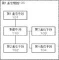
図1及び2を参照し、第1の実施形態に係る通信機器について説明する。図1は、第1の実施形態に係る通信機器のブロック図である。図1に示されるように、本発明の第1の実施形態に係る第1通信機器100は、第1通信手段101と、第2通信手段102と、第3通信手段103を有する。また、本発明の第1の実施形態に係る第1通信機器100は、後述する第1通信手段101、第2通信手段102、及び第3通信手段103の起動及び待機を制御する制御手段110を有する。第1通信機器100は、第1通信手段101の通信先と第3通信手段103の通信先を中継通信することができる。[First Embodiment]
A communication device according to the first embodiment will be described with reference to FIGS. 1 and 2. FIG. 1 is a block diagram of a communication device according to the first embodiment. As shown in FIG. 1, the first communication device 100 according to the first embodiment of the present invention includes a
第1通信手段101、第2通信手段102、及び第3通信手段103は、種々の通信方式を採用する通信手段を用いることができる。それぞれの通信手段が採用する通信方式は、全て同じであっても良いし、異なっていても良い。 The first communication means 101, the second communication means 102, and the third communication means 103 can use communication means that employ various communication methods. The communication methods employed by the respective communication means may all be the same or different.
それぞれの通信手段は、二つのモードに切り替わる。二つのモードは、起動の状態と、起動の状態よりも消費電力が少ない、又は電力を消費しない、待機の状態からなる。制御手段110は、それぞれの通信手段のモードを切り替えることができる。 Each communication means switches to two modes. The two modes consist of a startup state and a standby state that consumes less power or does not consume power than the startup state. The control means 110 can switch the mode of each communication means.
第1の実施形態に係る第1通信機器100は、第1通信手段101の通信先と第3通信手段103の通信先を中継通信することができる。例えば、第1通信手段101がパーソナルコンピューターと通信し、第3通信手段103が無線基地局と通信する場合、パーソナルコンピューターと無線基地局との間で、通信を行うことができる。 The first communication device 100 according to the first embodiment can perform relay communication between the communication destination of the
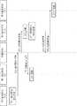
次に図2を用いて、本発明の第1の実施形態に係る第1通信機器100の動作について説明する。図2は、第1の実施形態に係る第1通信機器100の動作を示すシーケンス図である。上方から下方へ向かって時間が経過するものとする。以下に、第1の実施形態に係る第1通信機器100が中継通信を開始する際の動作を説明する。第1の実施形態に係る第1通信機器100において、中継通信を開始する前は、第1通信手段101は待機の状態にある。一方で第2通信手段102は起動の状態にある。 Next, the operation of the first communication device 100 according to the first embodiment of the present invention will be described with reference to FIG. FIG. 2 is a sequence diagram showing an operation of the first communication device 100 according to the first embodiment. It is assumed that time elapses from above to below. The operation when the first communication device 100 according to the first embodiment starts relay communication will be described below. In the first communication device 100 according to the first embodiment, the
第2通信手段102が、中継通信を開始する通信開始信号を受信すると(A1)、第2通信手段102は制御手段110に通信開始信号を送信する(A2)。制御手段110は、通信開始信号を受信すると、第3通信手段103を起動させる起動要求信号を第3通信手段103に送信し(A3)、第3通信手段103は起動要求信号を受信して、起動する(A4)。 When the second communication means 102 receives a communication start signal for starting relay communication (A1), the second communication means 102 transmits a communication start signal to the control means 110 (A2). Upon receiving the communication start signal, the
一方で制御手段110は、第3通信手段103を起動させる起動要求信号を第3通信手段103に送信した後に、第1通信手段101を起動させる起動要求信号を第1通信手段101に送信する(A5)。第1通信手段101は、起動要求信号を受信して、起動する(A6)。 On the other hand, the control means 110 transmits an activation request signal for activating the third communication means 103 to the third communication means 103 and then transmits an activation request signal for activating the first communication means 101 to the first communication means 101 ( A5). The first communication means 101 receives the activation request signal and activates it (A6).
第1の実施形態に係る第1通信機器100によれば、第3通信手段103を起動させる起動要求信号を第3通信手段103に送信した後に、第1通信手段101を起動させる起動要求信号を第1通信手段101に送信する。したがって、第1通信手段101の認証や起動を待たずに、第3通信手段103を起動することができ、中継通信を早期に確立することができる。 According to the first communication device 100 according to the first embodiment, after the activation request signal for activating the
なお、種々の通信手段においては、通信速度が高くなるほど消費電力が大きくなることが多い。本発明の第1の実施形態に係る第1通信機器100によれば、第2通信手段102として第1通信手段101より通信速度が低く消費電力が小さい通信手段を採用する場合、第1通信機器100全体の消費電力の低下と、高速な中継通信を両立することができる。すなわち、中継通信を行う際には、通信速度がより高い第1通信手段101を用いることで高速な中継通信を実現することができる。一方、中継通信を行わずに通信開始信号の受信を待つ際には、高速な通信が求められないことから、消費電力がより小さい第2通信手段102を用いることにより、電力の消費を抑えることができる。 In various communication means, the power consumption often increases as the communication speed increases. According to the first communication device 100 according to the first embodiment of the present invention, when a communication unit having a lower communication speed and lower power consumption than the
また、本発明の第1の実施形態に係る第1通信機器100によれば、第3通信手段103が第1通信手段101よりも通信の確立に時間を要する場合、中継通信の確立を早めることができる。すなわち、第1の実施形態に係る第1通信機器100では、第1通信手段101より先に第3通信手段103に対して起動要求信号を送信するため、中継通信の確立を早めることができる。 In addition, according to the first communication device 100 according to the first embodiment of the present invention, when the
[第2の実施形態]
図3及び4を参照し、第2の実施形態に係る通信機器について説明する。第2の実施形態は、第1の実施形態の変形例である。図3は、第2の実施形態に係る通信機器のブロック図である。第2の実施形態は、第4通信手段104以外は第1の実施形態と同様であり、図1から図2に記載の番号は図3から図4においても同じ構成を示す。[Second Embodiment]
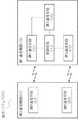
A communication apparatus according to the second embodiment will be described with reference to FIGS. The second embodiment is a modification of the first embodiment. FIG. 3 is a block diagram of a communication device according to the second embodiment. 2nd Embodiment is the same as that of 1st Embodiment except the 4th communication means 104, and the number as described in FIGS. 1-2 shows the same structure also in FIGS. 3-4.
図3に示されるように、本発明の第2の実施形態に係る第1通信機器100は、第1通信手段101と、第2通信手段102と、第3通信手段103と、第4通信手段104を有する。また、第1通信手段101、第2通信手段102、第3通信手段103、及び第4通信手段104の起動及び待機を制御する制御手段110を有する。第1通信機器100は、第1通信手段101の通信先と第3通信手段103の通信先を中継通信することができる。また、第1通信機器100は、第1通信手段101の通信先と第4通信手段104の通信先を中継通信することができる。 As shown in FIG. 3, the first communication device 100 according to the second embodiment of the present invention includes a
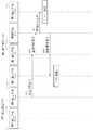
次に図4を用いて、本発明の第2の実施形態に係る第1通信機器100の動作について説明する。図4は、第2の実施形態に係る第1通信機器100の動作を示すシーケンス図である。以下に、第2の実施形態に係る第1通信機器100が中継通信を開始する際の動作を説明する。第2の実施形態に係る第1通信機器100において、中継通信を開始する前は、第1通信手段101は待機の状態にある。一方で第2通信手段102は、起動の状態にある。 Next, the operation of the first communication device 100 according to the second embodiment of the present invention will be described using FIG. FIG. 4 is a sequence diagram illustrating an operation of the first communication device 100 according to the second embodiment. The operation when the first communication device 100 according to the second embodiment starts relay communication will be described below. In the first communication device 100 according to the second embodiment, the
図4のB1〜B6までは、第1の実施形態に係る図2のA1〜A6までと同じである。第3通信手段103は、起動(B4)の後に、通信先に対して接続要求信号を送信する(B7)。第3通信手段103の通信先との接続が確立できない場合は、第3通信手段103は非接続信号を制御手段110に送信する(B8)。非接続信号は、例えば、一定時間以上、第3通信手段103の通信先との通信が確立できない場合に送信するように設定することができる。 B1 to B6 in FIG. 4 are the same as A1 to A6 in FIG. 2 according to the first embodiment. The 3rd communication means 103 transmits a connection request signal with respect to a communication destination after starting (B4) (B7). When the connection with the communication destination of the
制御手段110は非接続信号を受信すると、第4通信手段104を起動する起動要求信号を第4通信手段104に送る(B9)。第4通信手段104は、起動要求信号を受信すると、起動する(B10)。第4通信手段104が起動することにより、第1通信手段101の通信先と第4通信手段104の通信先の中継通信を試みることができる。 When receiving the non-connection signal, the
第2の実施形態に係る第1通信機器100によれば、第3通信手段103の通信手段が通信を行うことができない場合、制御手段110は、第4通信手段104を起動させる起動要求信号を第4通信手段104に送信する。したがって、第3通信手段103の通信を行うことができなくても、第4通信手段104により中継通信を試みることができる。 According to the first communication device 100 according to the second embodiment, when the communication unit of the
[第3の実施形態]
図5を参照し、第3の実施形態に係る通信機器について説明する。第3の実施形態は、第1及び第2の実施形態の変形例である。以下では第1の実施形態の変形例として説明する。図5は、第3の実施形態に係る通信機器の動作を示すシーケンス図である。第3の実施形態の構成は、第1の実施形態と同様であり、図1及び図2に記載の番号は図5においても同じ構成を示す。以下に、第3の実施形態に係る第1通信機器100が中継通信を開始する際の動作を説明する。[Third Embodiment]
A communication device according to the third embodiment will be described with reference to FIG. The third embodiment is a modification of the first and second embodiments. Below, it demonstrates as a modification of 1st Embodiment. FIG. 5 is a sequence diagram illustrating the operation of the communication device according to the third embodiment. The configuration of the third embodiment is the same as that of the first embodiment, and the numbers described in FIGS. 1 and 2 indicate the same configuration in FIG. The operation when the first communication device 100 according to the third embodiment starts relay communication will be described below.
第3の実施形態に係る第1通信機器100において、中継通信を開始する前は、第1通信手段101は待機の状態にある。一方で第2通信手段102は、起動の状態にある。 In the first communication device 100 according to the third embodiment, before the relay communication is started, the
図5のC1〜C6までは、第1の実施形態に係る図2のA1〜A6までと同じである。第1通信手段101は、起動すると(C6)、起動応答信号を制御手段110に送信する(C7)。起動応答信号を受信した制御手段110は、第2通信手段102を待機させる待機要求信号を第2制御手段102に送信する(C8)。待機要求信号を受信した第2通信手段102は、待機する(C9)。 C1 to C6 in FIG. 5 are the same as A1 to A6 in FIG. 2 according to the first embodiment. When the first communication means 101 is activated (C6), it transmits an activation response signal to the control means 110 (C7). Receiving the activation response signal, the
第3の実施形態に係る第1通信機器100によれば、第1通信手段101が起動した後に、第2通信手段102を待機の状態にさせるため、消費電力を減らすことができる。 According to the first communication device 100 according to the third embodiment, after the
[第4の実施形態]
図6を参照し、第4の実施形態に係る通信機器について説明する。第4の実施形態は、第1乃至第3の実施形態の変形例である。以下では第1の実施形態の変形例として説明する。図6は、第4の実施形態に係る通信機器の動作を示すシーケンス図である。第4の実施形態の構成は、第1の実施形態と同様であり、図1及び図2に記載の番号は図6においても同じ構成を示す。以下に、第4の実施形態に係る第1通信機器100が中継通信を中止する際の動作を説明する。[Fourth Embodiment]
A communication device according to the fourth embodiment will be described with reference to FIG. The fourth embodiment is a modification of the first to third embodiments. Below, it demonstrates as a modification of 1st Embodiment. FIG. 6 is a sequence diagram illustrating an operation of the communication device according to the fourth embodiment. The configuration of the fourth embodiment is the same as that of the first embodiment, and the numbers described in FIGS. 1 and 2 indicate the same configuration in FIG. The operation when the first communication device 100 according to the fourth embodiment stops relay communication will be described below.
第4の実施形態に係る第1通信機器100において、中継通信を中止する前は、第1通信手段101は起動の状態にある。一方で第2通信手段102は、待機の状態にある。 In the first communication device 100 according to the fourth embodiment, before the relay communication is stopped, the
第1通信手段101が、中継通信を中止する通信切断信号を受信すると(E1)、第1通信手段101は制御手段110に通信切断信号を送信する(E2)。制御手段110は、通信切断信号を受信すると、第3通信手段103を待機させる待機要求信号を第3通信手段103に送信し(E3)、第3通信手段103は待機要求信号を受信して、待機する(E4)。 When the
一方で制御手段110は、第3通信手段103を待機させる待機要求信号を第3通信手段103に送信した後に、第2通信手段102を起動させる起動要求信号を第2通信手段102に送信する(E5)。第2通信手段102は、起動要求信号を受信して、起動する(E6)。 On the other hand, the
第4の実施形態に係る第1通信機器100によれば、第3通信手段103を待機させる起動要求信号を第3通信手段103に送信した後に、第2通信手段102を起動させる起動要求信号を第2通信手段102に送信する。したがって、第1通信手段101の切断を待たずに、早期に第2通信手段102を起動することができる。 According to the first communication device 100 according to the fourth embodiment, the activation request signal for activating the
[第5の実施形態]
図7を参照し、第5の実施形態に係る通信機器について説明する。第5の実施形態は、第4の実施形態の変形例である。図7は、第5の実施形態に係る通信機器の動作を示すシーケンス図である。第5の実施形態の構成は、第4の実施形態と同様であり、図6に記載の番号は図7においても同じ構成を示す。以下に、第5の実施形態に係る第1通信機器100が中継通信を中止する際の動作を説明する。[Fifth Embodiment]
A communication device according to the fifth embodiment will be described with reference to FIG. The fifth embodiment is a modification of the fourth embodiment. FIG. 7 is a sequence diagram illustrating the operation of the communication device according to the fifth embodiment. The configuration of the fifth embodiment is the same as that of the fourth embodiment, and the numbers shown in FIG. 6 indicate the same configurations in FIG. The operation when the first communication device 100 according to the fifth embodiment stops relay communication will be described below.
図7のF1〜F6までは、第4の実施形態に係る図6のE1〜E6までと同じである。第2通信手段102は、起動すると(F6)起動応答信号を制御手段110に送信する(F7)。起動応答信号を受信した制御手段110は、待機要求信号を第1制御手段101に送信する(F8)。待機要求信号を受信した第1通信手段101は、待機する(F9)。 F1 to F6 in FIG. 7 are the same as E1 to E6 in FIG. 6 according to the fourth embodiment. When the second communication means 102 is activated (F6), it transmits an activation response signal to the control means 110 (F7). The control means 110 that has received the activation response signal transmits a standby request signal to the first control means 101 (F8). The first communication means 101 that has received the standby request signal waits (F9).
第5の実施形態に係る第1通信機器100によれば、第2通信手段102が起動した後に、第1通信手段101を待機の状態にするため、消費電力を減らすことができる。 According to the first communication device 100 according to the fifth embodiment, after the
[第6の実施形態]
図8乃至10を参照し、第6の実施形態に係る通信システムについて説明する。第6の実施形態は、第1乃至第5の実施形態の変形例である。以下では第1及び第4の実施形態の変形例として説明する。図8は、第6の実施形態に係る通信システムのブロック図である。第1通信機器100は、第1乃至第5の実施形態の第1通信機器100と同じ構成であり、図1及び図2に記載の番号は図8から図10においても同じ構成を示す。[Sixth Embodiment]
A communication system according to the sixth embodiment will be described with reference to FIGS. The sixth embodiment is a modification of the first to fifth embodiments. Below, it demonstrates as a modification of 1st and 4th embodiment. FIG. 8 is a block diagram of a communication system according to the sixth embodiment. The first communication device 100 has the same configuration as the first communication device 100 of the first to fifth embodiments, and the numbers described in FIGS. 1 and 2 indicate the same configuration in FIGS. 8 to 10.
図8に示されるように、本発明の第6の実施形態に係る通信システム1000は、第1通信機器100と、第2通信機器200とを有する。第1通信機器100は、第1通信手段101と、第2通信手段102と、第3通信手段103と、第1〜3通信手段の起動及び待機を制御する制御手段110とを有する。 As shown in FIG. 8, a communication system 1000 according to the sixth embodiment of the present invention includes a first communication device 100 and a second communication device 200. The first communication device 100 includes a
第2通信機器200は、第1通信手段101と通信可能な第5通信手段201と、第2通信手段102と通信可能な第6通信手段202とを有する。第5通信手段201としては、第1通信手段101と通信可能であれば、いずれの通信手段も採用することができる。また、第6通信手段202としては、第2通信手段102と通信可能であれば、いずれの通信手段も採用することができる。 The second communication device 200 includes a
次に図9を用いて、本発明の第6の実施形態に係る通信システム1000の動作について説明する。図9は、第6の実施形態に係る通信システム1000の動作を示すシーケンス図である。以下に、第6の実施形態に係る通信システム1000が中継通信を開始する際の動作を説明する。第6の実施形態に係る通信システム1000において、中継通信を開始する前は、第1通信手段101は待機の状態にある。一方で第2通信手段102は、起動の状態にある。 Next, the operation of the communication system 1000 according to the sixth embodiment of the present invention will be described with reference to FIG. FIG. 9 is a sequence diagram showing an operation of the communication system 1000 according to the sixth embodiment. The operation when the communication system 1000 according to the sixth embodiment starts relay communication will be described below. In the communication system 1000 according to the sixth embodiment, the
第6通信手段202が中継通信を開始する通信開始信号を第2通信手段102に送信する(G1)。第2通信手段102は、通信開始信号を受信すると、制御手段110に通信開始信号を送信する(G2)。制御手段110は、通信開始信号を受信すると、第3通信手段103を起動させる起動要求信号を第3通信手段103に送信し(G3)、第3通信手段103は起動要求信号を受信して、起動する(G4)。 The sixth communication means 202 transmits a communication start signal for starting relay communication to the second communication means 102 (G1). When receiving the communication start signal, the
一方で制御手段110は、第3通信手段103を起動させる起動要求信号を第3通信手段103に送信した後に、第1通信手段101を起動させる起動要求信号を第1通信手段101に送信する(G5)。第1通信手段101は、起動要求信号を受信して、起動する(G6)。 On the other hand, the control means 110 transmits an activation request signal for activating the third communication means 103 to the third communication means 103 and then transmits an activation request signal for activating the first communication means 101 to the first communication means 101 ( G5). The first communication means 101 receives the activation request signal and activates it (G6).
第6の実施形態に係る通信システム1000によれば、第3通信手段103を起動させる起動要求信号を第3通信手段103に送信した後に、第1通信手段101を起動させる起動要求信号を第1通信手段101に送信する。したがって、第1通信手段101の認証や起動を待たずに、第3通信手段103を起動することができ、中継通信を早期に確立することができる。 According to the communication system 1000 according to the sixth embodiment, after the activation request signal for activating the
次に、第6の実施形態に係る通信システム1000が中継通信を中止する際の動作を説明する。 Next, an operation when the communication system 1000 according to the sixth embodiment stops relay communication will be described.
第6の実施形態に係る通信システム1000において、中継通信を中止する前は、第1通信手段101は起動の状態にある。一方で第2通信手段102は、待機の状態にある。 In the communication system 1000 according to the sixth embodiment, the
第5通信手段201は、第1通信手段101に中継通信を中止する通信切断信号を送信する(H1)。第1通信手段101は、通信切断信号を受信すると、制御手段110に通信切断信号を送信する(H2)。制御手段110は、通信切断信号を受信すると、第3通信手段103を待機させる待機要求信号を第3通信手段103に送信し(H3)、第3通信手段103は待機要求信号を受信して、待機する(H4)。 The
一方で制御手段110は、第3通信手段103を待機させる待機要求信号を第3通信手段103に送信した後に、第2通信手段102を起動させる起動要求信号を第2通信手段102に送信する(H5)。第2通信手段102は、起動要求信号を受信して、起動する(H6)。 On the other hand, the
第6の実施形態に係る通信システム1000によれば、第3通信手段103を待機させる起動要求信号を第3通信手段103に送信した後に、第2通信手段102を起動させる起動要求信号を第2通信手段102に送信する。したがって、第1通信手段101の切断を待たずに、早期に第2通信手段102を起動することができる。 According to the communication system 1000 according to the sixth embodiment, after the activation request signal for waiting the
[第7の実施形態]
図11乃至13を参照し、第7の実施形態に係る通信システム1000について説明する。第7の実施形態は、第6の実施形態の変形例である。図11は、第7の実施形態に係る通信システムのブロック図である。第1通信機器100及び第2通信機器200は、第6の実施形態の第1通信機器100及び第2通信機器200と同様であり、図8及び図10に記載の番号は図11から図13においても同じ構成を示す。[Seventh Embodiment]
A communication system 1000 according to the seventh embodiment will be described with reference to FIGS. The seventh embodiment is a modification of the sixth embodiment. FIG. 11 is a block diagram of a communication system according to the seventh embodiment. The first communication device 100 and the second communication device 200 are the same as the first communication device 100 and the second communication device 200 of the sixth embodiment, and the numbers shown in FIGS. The same configuration is shown in FIG.
図11に示されるように、本発明の第7の実施形態に係る通信システム1000は、第1通信機器100と、第2通信機器200と、第3通信機器300を有する。第1通信機器100は、第1通信手段101と、第2通信手段102と、第3通信手段103と、第1〜3通信手段の起動及び待機を制御する制御手段110とを有する。第2通信機器200は、第1通信手段101と通信可能な第5通信手段201と、第2通信手段102と通信可能な第6通信手段202とを有する。第3通信機器300は、第3通信手段103と通信可能な第7通信手段301を有する。第7通信手段301としては、第3通信手段103と通信可能であれば、いずれの通信手段も採用することができる。 As illustrated in FIG. 11, the communication system 1000 according to the seventh embodiment of the present invention includes a first communication device 100, a second communication device 200, and a third communication device 300. The first communication device 100 includes a
次に図12を用いて、本発明の第7の実施形態に係る通信システム1000の動作について説明する。図12は、第7の実施形態に係る通信システム1000の動作を示すシーケンス図である。以下に、第7の実施形態に係る通信システム1000が中継通信を開始する際の動作を説明する。第7の実施形態に係る通信システム1000において、中継通信を開始する前は、第1通信手段101は待機の状態にある。一方で第2通信手段102は、起動の状態にある。 Next, the operation of the communication system 1000 according to the seventh embodiment of the present invention will be described using FIG. FIG. 12 is a sequence diagram showing an operation of the communication system 1000 according to the seventh embodiment. The operation when the communication system 1000 according to the seventh embodiment starts relay communication will be described below. In the communication system 1000 according to the seventh embodiment, the
第6通信手段202が中継通信を開始する通信開始信号を第2通信手段102に送信する(I1)。第2通信手段102は、通信開始信号を受信すると、制御手段110に通信開始信号を送信する(I2)。制御手段110は、通信開始信号を受信すると、第3通信手段103を起動させる起動要求信号を第3通信手段103に送信し(I3)、第3通信手段103は起動要求信号を受信して、起動する(I4)。 The sixth communication means 202 transmits a communication start signal for starting relay communication to the second communication means 102 (I1). When receiving the communication start signal, the
一方で制御手段110は、第3通信手段103を起動させる起動要求信号を第3通信手段103に送信した後に、第1通信手段101を起動させる起動要求信号を第1通信手段101に送信する(I5)。第1通信手段101は、起動要求信号を受信して、起動する(I6)。第3通信手段103は、第7通信手段との通信を確立する接続要求信号を送信する(I7)。 On the other hand, the control means 110 transmits an activation request signal for activating the third communication means 103 to the third communication means 103 and then transmits an activation request signal for activating the first communication means 101 to the first communication means 101 ( I5). The first communication means 101 receives the activation request signal and activates (I6). The third communication means 103 transmits a connection request signal for establishing communication with the seventh communication means (I7).
第7の実施形態に係る通信システム1000によれば、第3通信手段103を起動させる起動要求信号を第3通信手段103に送信した後に、第1通信手段101を起動させる起動要求信号を第1通信手段101に送信する。したがって、第1通信手段101の認証や起動を待たずに、第3通信手段103を起動することができ、中継通信を早期に確立することができる。 According to the communication system 1000 according to the seventh embodiment, after the activation request signal for activating the
次に、第7の実施形態に係る通信システム1000が中継通信を中止する際の動作を説明する。 Next, an operation when the communication system 1000 according to the seventh embodiment stops relay communication will be described.
第7の実施形態に係る通信システム1000において、中継通信を中止する前は、第1通信手段101は起動の状態にある。一方で第2通信手段102は、待機の状態にある。 In the communication system 1000 according to the seventh embodiment, the
第5通信手段201は、第1通信手段101に中継通信を中止する通信切断信号を送信する(J1)。第1通信手段101は、通信切断信号を受信すると、制御手段110に通信切断信号を送信する(J2)。制御手段110は、通信切断信号を受信すると、第3通信手段103を待機させる待機要求信号を第3通信手段103に送信し(J3)、第3通信手段103は待機要求信号を受信して、待機する(J4)。 The
一方で制御手段110は、第3通信手段103を待機させる待機要求信号を第3通信手段103に送信した後に、第2通信手段102を起動させる起動要求信号を第2通信手段102に送信する(J5)。第2通信手段102は、起動要求信号を受信して、起動する(J6)。第3通信手段103は、第7通信手段301との通信を切断する切断要求信号を送信する(J7)。 On the other hand, the
第7の実施形態に係る通信システム1000によれば、第3通信手段103を待機させる起動要求信号を第3通信手段103に送信した後に、第2通信手段102を起動させる起動要求信号を第2通信手段102に送信する。したがって、第1通信手段101の切断を待たずに、早期に第2通信手段102を起動することができる。 According to the communication system 1000 according to the seventh embodiment, after the activation request signal for waiting the
本発明の通信機器及び通信機器の制御方法は、上記実施形態に基づいて説明されているが、上記実施形態に限定されることなく、本発明の範囲内において、かつ本発明の基本的技術思想に基づいて、上記実施形態に対し種々の変形、変更及び改良を含むことができることはいうまでもない。また、本発明の請求の範囲の枠内において、種々の開示要素の多様な組み合わせ・置換ないし選択が可能である。本発明のさらなる課題、目的及び展開形態は、請求の範囲を含む本発明の全開示事項からも明らかにされる。 The communication device and the control method of the communication device of the present invention have been described based on the above embodiment, but are not limited to the above embodiment, and are within the scope of the present invention and the basic technical idea of the present invention. It goes without saying that various modifications, changes and improvements can be included in the above embodiment based on the above. Further, various combinations, substitutions, or selections of various disclosed elements are possible within the scope of the claims of the present invention. Further problems, objects, and developments of the present invention will become apparent from the entire disclosure of the present invention including the claims.
100 第1通信機器
101 第1通信手段
102 第2通信手段
103 第3通信手段
104 第4通信手段
110 制御手段
200 第2通信機器
201 第5通信手段
202 第6通信手段
300 第3通信機器
301 第7通信手段
400 遠隔制御システム
500 通信装置
510 受信整流部
530 送受信部
550 判定部
570 電源制御部
600 通信装置
610 第1制御通信部
630 第2制御通信部
1000 通信システムDESCRIPTION OF SYMBOLS 100
Claims (10)
Translated fromJapanese第2通信手段と、
第3通信手段と、
前記第1通信手段が待機の状態で、前記第2通信手段が起動の状態である際に、前記第1通信手段の通信先と前記第3通信手段の通信先の中継通信を開始する通信開始信号を受信すると、前記第3通信手段を起動させる起動要求信号を前記第3通信手段に送信した後に、前記第1通信手段を起動させる起動要求信号を前記第1通信手段に送信する制御手段とを備え、
前記第2通信手段は、前記第1通信手段と前記第1通信手段の通信先との通信で用いられる通信方式で前記第1通信手段の通信先から送信された前記通信開始信号を受信する
ことを特徴とする、通信機器。First communication means;
A second communication means;
A third communication means;
Start of communication for starting relay communication between the communication destination of the first communication means and the communication destination of the third communication means when the first communication means is in a standby state and the second communication means is in an activated state Control means for transmitting an activation request signal for activating the first communication means to the first communication means after transmitting an activation request signal for activating the third communication means to the third communication means upon receiving a signal; equipped witha,
The second communication means receives the communication start signal transmitted from the communication destination of the first communication means in a communication method used for communication between the first communication means and the communication destination of the first communication means < A communication device characterized by the above.
前記通信機器は、さらに、
起動して通信先と接続された場合に、前記通信先と、前記第1通信手段の通信先との間の通信を中継可能な第4通信手段を有し、
前記制御手段は、前記第3通信手段が起動した後に、前記第3通信手段が通信を行うことができない場合は、前記第4通信手段を起動させる起動要求信号を前記第4通信手段に送信することを特徴とする、
通信機器。The communication device according to claim 1,
The communication device further includes:
A fourth communication meanscapable of relaying communication between the communication destination andthe communication destination of the first communication meanswhen activated and connected to the communication destination;
The control means transmits an activation request signal for activating the fourth communication means to the fourth communication means when the third communication means cannot communicate after the third communication means is activated. It is characterized by
Communication equipment.
前記制御手段は、前記起動要求信号を受信した前記第1通信手段が起動したことを示す起動応答信号を受信した後に、前記第2通信手段を待機させる待機要求信号を前記第2通信手段に送信することを特徴とする、通信機器。The communication device according to claim 1 or 2,
The control means transmits a standby request signal for waiting the second communication means to the second communication means after receiving the activation response signal indicating that the first communication means having received the activation request signal has been activated. A communication device, characterized by:
前記第2通信手段が待機の状態で、前記第1通信手段が起動の状態である際に、
前記制御手段は、前記第1通信手段が前記中継通信を中止する通信切断信号を受信すると、前記第3通信手段を待機させる待機要求信号を前記第3通信手段に送信した後に、前記第2通信手段を起動させる起動要求信号を前記第2通信手段に送信することを特徴とする、
通信機器。A communication device according toany one of claims 1to 3,
When the second communication means is in a standby state and the first communication means is in an activated state,
When the first communication means receives a communication disconnection signal for stopping the relay communication, the control means transmits a standby request signal for waiting the third communication means to the third communication means, and then the second communication. Transmitting an activation request signal for activating the means to the second communication means,
Communication equipment.
前記制御手段は、前記起動要求信号を受信した前記第2通信手段が起動したことを示す起動応答信号を受信した後に、前記第1通信手段を待機させる待機要求信号を前記第1通信手段に送信することを特徴とする、通信機器。The communication device according to claim 4,
The control means transmits a standby request signal for waiting the first communication means to the first communication means after receiving an activation response signal indicating that the second communication means having received the activation request signal has been activated. A communication device, characterized by:
第2通信機器とを有し、
前記第1通信機器は、請求項1乃至6のうちいずれかに記載の通信機器であり、
前記第2通信機器は、
前記第1通信手段と通信可能な第5通信手段と、
前記第2通信手段と通信可能な第6通信手段とを有し、
前記第6通信手段は前記通信開始信号を前記第2通信手段に送信し、
前記第5通信手段が、前記中継通信を中止する通信切断信号を前記第1通信手段に送信することを特徴とする、
通信システム。A first communication device;
A second communication device,
It said first communication device is a communication device according toany one of claims 1 to 6,
The second communication device is:
Fifth communication means capable of communicating with the first communication means;
Sixth communication means capable of communicating with the second communication means;
The sixth communication means transmits the communication start signal to the second communication means;
The fifth communication means transmitsa communication disconnection signal forcanceling the relay communication to the first communication means.
Communications system.
第3通信機器を有し、
前記第3通信機器は、
前記第3通信手段と通信可能な第7通信手段を有することを特徴とする、通信システム。A communication system according to claim 7;
Having a third communication device,
The third communication device is:
A communication system comprising seventh communication means capable of communicating with the third communication means.
前記第1通信手段が待機の状態で、前記第2通信手段が起動の状態である際に、前記第1通信手段と前記第1通信手段の通信先との通信で用いられる通信方式で前記第1通信手段の通信先から送信され、前記中継通信を開始する通信開始信号を前記第2通信手段が受信すると、前記第3通信手段を起動させる起動要求信号を前記第3通信手段に送信した後に、前記第1通信手段を起動させる起動要求信号を前記第1通信手段に送信するように制御することを特徴とする、
通信機器の制御方法。A control method for a communication device, comprising: a first communication unit; a second communication unit; and a third communication unit, wherein the communication destination of the first communication unit and the communication destination of the third communication unit are relayed. ,
When the first communication means is in a standby state and the second communication means is in an activated state, thecommunication method used for communication between the first communication means and the communication destination of the first communication means is the first communication means. When the second communication unit receives a communication start signaltransmitted from a communication destination of one communication unit and starts the relay communication, after transmitting an activation request signal for starting the third communication unit to the third communication unit And controlling to transmit an activation request signal for activating the first communication means to the first communication means,
Control method of communication equipment.
前記通信機器はさらに第4通信手段を有し、
前記第1通信手段の通信先と前記第4通信手段の通信先を中継通信することができ、
前記第3通信手段が起動した後に、前記第3通信手段が通信を行うことができない場合は、前記第4通信手段を起動させる起動要求信号を前記第4通信手段に送信するように制御することを特徴とする、
通信機器の制御方法。A communication device control method according to claim 9,
The communication device further includes fourth communication means,
The communication destination of the first communication means and the communication destination of the fourth communication means can be relay-communicated,
When the third communication unit cannot communicate after the third communication unit is activated, control is performed to transmit an activation request signal for activating the fourth communication unit to the fourth communication unit. Characterized by the
Control method of communication equipment.
Priority Applications (1)
| Application Number | Priority Date | Filing Date | Title |
|---|---|---|---|
| JP2012204375AJP5722853B2 (en) | 2012-09-18 | 2012-09-18 | COMMUNICATION DEVICE AND COMMUNICATION DEVICE CONTROL METHOD |
Applications Claiming Priority (1)
| Application Number | Priority Date | Filing Date | Title |
|---|---|---|---|
| JP2012204375AJP5722853B2 (en) | 2012-09-18 | 2012-09-18 | COMMUNICATION DEVICE AND COMMUNICATION DEVICE CONTROL METHOD |
Publications (2)
| Publication Number | Publication Date |
|---|---|
| JP2014060586A JP2014060586A (en) | 2014-04-03 |
| JP5722853B2true JP5722853B2 (en) | 2015-05-27 |
Family
ID=50616681
Family Applications (1)
| Application Number | Title | Priority Date | Filing Date |
|---|---|---|---|
| JP2012204375AActiveJP5722853B2 (en) | 2012-09-18 | 2012-09-18 | COMMUNICATION DEVICE AND COMMUNICATION DEVICE CONTROL METHOD |
Country Status (1)
| Country | Link |
|---|---|
| JP (1) | JP5722853B2 (en) |
Cited By (1)
| Publication number | Priority date | Publication date | Assignee | Title |
|---|---|---|---|---|
| JP3382426B2 (en) | 1995-09-18 | 2003-03-04 | キヤノン株式会社 | Article transfer device |
Families Citing this family (1)
| Publication number | Priority date | Publication date | Assignee | Title |
|---|---|---|---|---|
| JP6272216B2 (en)* | 2014-12-25 | 2018-01-31 | Necプラットフォームズ株式会社 | RELAY DEVICE, RELAY DEVICE CONTROL METHOD, AND RELAY DEVICE PROGRAM |
Family Cites Families (7)
| Publication number | Priority date | Publication date | Assignee | Title |
|---|---|---|---|---|
| JP4273901B2 (en)* | 2003-09-25 | 2009-06-03 | パナソニック電工株式会社 | Wireless relay device |
| US8478360B2 (en)* | 2008-03-03 | 2013-07-02 | Qualcomm Incorporated | Facilitating power conservation in wireless client terminals |
| JP5082150B2 (en)* | 2010-05-24 | 2012-11-28 | Necアクセステクニカ株式会社 | Router control method and wireless LAN router apparatus |
| US8817856B2 (en)* | 2010-05-27 | 2014-08-26 | Lg Electronics Inc. | Method and apparatus for controlling suspend mode in dual modem device |
| JP5269846B2 (en)* | 2010-08-23 | 2013-08-21 | 日本電信電話株式会社 | Area analysis system, wireless router and area analysis server |
| JP5190568B2 (en)* | 2011-02-23 | 2013-04-24 | 株式会社国際電気通信基礎技術研究所 | Radio base station and radio communication system using the same |
| JP5960558B2 (en)* | 2012-09-06 | 2016-08-02 | Necプラットフォームズ株式会社 | Wireless router device |
- 2012
- 2012-09-18JPJP2012204375Apatent/JP5722853B2/enactiveActive
Cited By (1)
| Publication number | Priority date | Publication date | Assignee | Title |
|---|---|---|---|---|
| JP3382426B2 (en) | 1995-09-18 | 2003-03-04 | キヤノン株式会社 | Article transfer device |
Also Published As
| Publication number | Publication date |
|---|---|
| JP2014060586A (en) | 2014-04-03 |
Similar Documents
| Publication | Publication Date | Title |
|---|---|---|
| JP2009545923A5 (en) | ||
| JP2009278240A5 (en) | ||
| JP5303582B2 (en) | Portable terminal device and communication switching method | |
| KR20150100205A (en) | Method and apparatus for saving power of user equipment in wireless communication system supporing device to device communication | |
| WO2007078051A3 (en) | Method for handover in mobile communication system | |
| JP2010028753A (en) | Communication device and communication control method | |
| JP5960558B2 (en) | Wireless router device | |
| JP2010045428A5 (en) | ||
| JP2012022562A5 (en) | Information processing apparatus, information processing system, information processing apparatus control method, communication state confirmation method, and program | |
| JP2010283696A5 (en) | ||
| JP2010072257A5 (en) | ||
| CA2510659A1 (en) | Communication system and communication terminal apparatus | |
| JP2015035911A5 (en) | ||
| CN103379197A (en) | Method and system for automatically switching wireless communication | |
| JP5722853B2 (en) | COMMUNICATION DEVICE AND COMMUNICATION DEVICE CONTROL METHOD | |
| JP2014006867A (en) | Wireless communication device and wireless communication system | |
| JP4439476B2 (en) | Data transfer device and mobile phone | |
| JP6316033B2 (en) | Information processing apparatus, control method therefor, and storage medium | |
| JP5863368B2 (en) | COMMUNICATION DEVICE, CONTROL METHOD AND PROGRAM FOR COMMUNICATION DEVICE | |
| JP5288618B2 (en) | Portable device | |
| JP2009290718A (en) | Wireless data communication system | |
| JP2011019089A (en) | Wireless lan system | |
| JP6068104B2 (en) | COMMUNICATION DEVICE AND COMMUNICATION DEVICE CONTROL METHOD | |
| JP6272216B2 (en) | RELAY DEVICE, RELAY DEVICE CONTROL METHOD, AND RELAY DEVICE PROGRAM | |
| JP5010718B2 (en) | Communication apparatus and communication control method |
Legal Events
| Date | Code | Title | Description |
|---|---|---|---|
| A621 | Written request for application examination | Free format text:JAPANESE INTERMEDIATE CODE: A621 Effective date:20140116 | |
| A711 | Notification of change in applicant | Free format text:JAPANESE INTERMEDIATE CODE: A712 Effective date:20140805 | |
| A977 | Report on retrieval | Free format text:JAPANESE INTERMEDIATE CODE: A971007 Effective date:20141210 | |
| A131 | Notification of reasons for refusal | Free format text:JAPANESE INTERMEDIATE CODE: A131 Effective date:20141216 | |
| A521 | Written amendment | Free format text:JAPANESE INTERMEDIATE CODE: A523 Effective date:20150216 | |
| TRDD | Decision of grant or rejection written | ||
| A01 | Written decision to grant a patent or to grant a registration (utility model) | Free format text:JAPANESE INTERMEDIATE CODE: A01 Effective date:20150303 | |
| A61 | First payment of annual fees (during grant procedure) | Free format text:JAPANESE INTERMEDIATE CODE: A61 Effective date:20150326 | |
| R150 | Certificate of patent or registration of utility model | Ref document number:5722853 Country of ref document:JP Free format text:JAPANESE INTERMEDIATE CODE: R150 |