JP5722747B2 - Robot joint structure and robot incorporating this joint structure - Google Patents
Robot joint structure and robot incorporating this joint structureDownload PDFInfo
- Publication number
- JP5722747B2 JP5722747B2JP2011233250AJP2011233250AJP5722747B2JP 5722747 B2JP5722747 B2JP 5722747B2JP 2011233250 AJP2011233250 AJP 2011233250AJP 2011233250 AJP2011233250 AJP 2011233250AJP 5722747 B2JP5722747 B2JP 5722747B2
- Authority
- JP
- Japan
- Prior art keywords
- axis
- intermediate link
- robot
- joint
- joint structure
- Prior art date
- Legal status (The legal status is an assumption and is not a legal conclusion. Google has not performed a legal analysis and makes no representation as to the accuracy of the status listed.)
- Active
Links
- 230000002093peripheral effectEffects0.000claimsdescription4
- 239000000543intermediateSubstances0.000description78
- 230000033001locomotionEffects0.000description19
- 210000000689upper legAnatomy0.000description18
- 210000004394hip jointAnatomy0.000description13
- 210000002683footAnatomy0.000description11
- 210000002414legAnatomy0.000description8
- 210000001503jointAnatomy0.000description7
- 210000000544articulatio talocruralisAnatomy0.000description6
- 210000003857wrist jointAnatomy0.000description5
- 210000000629knee jointAnatomy0.000description2
- 230000001429stepping effectEffects0.000description2
- 238000013459approachMethods0.000description1
- 230000004323axial lengthEffects0.000description1
- 230000001364causal effectEffects0.000description1
- 238000004891communicationMethods0.000description1
- 230000008878couplingEffects0.000description1
- 238000010168coupling processMethods0.000description1
- 238000005859coupling reactionMethods0.000description1
- 230000000694effectsEffects0.000description1
- 230000005484gravityEffects0.000description1
- 210000003205muscleAnatomy0.000description1
- 210000004197pelvisAnatomy0.000description1
- 238000012827research and developmentMethods0.000description1
- 230000001360synchronised effectEffects0.000description1
Images


Classifications
- B—PERFORMING OPERATIONS; TRANSPORTING
- B25—HAND TOOLS; PORTABLE POWER-DRIVEN TOOLS; MANIPULATORS
- B25J—MANIPULATORS; CHAMBERS PROVIDED WITH MANIPULATION DEVICES
- B25J17/00—Joints
- B25J17/02—Wrist joints
- B25J17/0258—Two-dimensional joints
- B—PERFORMING OPERATIONS; TRANSPORTING
- B25—HAND TOOLS; PORTABLE POWER-DRIVEN TOOLS; MANIPULATORS
- B25J—MANIPULATORS; CHAMBERS PROVIDED WITH MANIPULATION DEVICES
- B25J17/00—Joints
- B25J17/02—Wrist joints
- B25J17/0258—Two-dimensional joints
- B25J17/0266—Two-dimensional joints comprising more than two actuating or connecting rods
- Y—GENERAL TAGGING OF NEW TECHNOLOGICAL DEVELOPMENTS; GENERAL TAGGING OF CROSS-SECTIONAL TECHNOLOGIES SPANNING OVER SEVERAL SECTIONS OF THE IPC; TECHNICAL SUBJECTS COVERED BY FORMER USPC CROSS-REFERENCE ART COLLECTIONS [XRACs] AND DIGESTS
- Y10—TECHNICAL SUBJECTS COVERED BY FORMER USPC
- Y10T—TECHNICAL SUBJECTS COVERED BY FORMER US CLASSIFICATION
- Y10T74/00—Machine element or mechanism
- Y10T74/20—Control lever and linkage systems
- Y10T74/20207—Multiple controlling elements for single controlled element
- Y10T74/20305—Robotic arm
- Y10T74/20329—Joint between elements
- Y10T74/20335—Wrist
Landscapes
- Engineering & Computer Science (AREA)
- Robotics (AREA)
- Mechanical Engineering (AREA)
- Manipulator (AREA)
Description
Translated fromJapanese本発明は、ロボットの関節構造及びこの関節構造が組み込まれたロボットに関し、特に関節構造が第一部材及び第二部材を備え、第一部材に対して第二部材を直角な二軸の回りに相対的に回転させるロボットの関節構造及びこの関節構造が組み込まれたロボットに関する。 The present invention relates to a joint structure of a robot and a robot incorporating the joint structure, and in particular, the joint structure includes a first member and a second member, and the second member is rotated around two axes perpendicular to the first member. The present invention relates to a joint structure of a robot that rotates relatively and a robot in which the joint structure is incorporated.
近年、産業用ロボットだけでなく、民生用として様々な役目を担うロボットの研究開発が盛んになされている。ロボットの中でも直立歩行が可能な人間型ロボット(ヒューマノイドロボット)は、人間の行動を代替できるものとして期待されている。かかる人間型ロボットは、脚部、腕部、首部等に関節を有し、人間に近い動作を可能としている。 In recent years, research and development of not only industrial robots but also robots that have various roles for consumer use have been actively conducted. Among robots, humanoid robots (humanoid robots) that can stand upright are expected to replace human behavior. Such a humanoid robot has joints in the leg portion, arm portion, neck portion, and the like, and can operate close to a human.
ところで、ロボットの関節には、自由度が1のものから3以上のものまで様々なものがある。自由度とは、自由に運動できる方向の個数であり、例えば、ピッチ軸のみの回りを回転できる関節の自由度は1であり、ピッチ軸及びヨー軸の二軸の回りを回転できる関節の自由度は2である。従来のロボットの関節構造においては、自由度が2以上の関節を実現するためには、回転系のサーボモータを2個以上組み合わせるのが一般的であった。すなわち、回転系サーボモータを2個以上用意し、回転系のサーボモータの回転軸が互いに直角になるように組み合わせていた(例えば特許文献1参照)。 By the way, there are various types of robot joints ranging from one having one degree of freedom to three or more degrees of freedom. The degree of freedom is the number of directions that can freely move. For example, the degree of freedom of a joint that can rotate only around the pitch axis is 1, and the degree of freedom of the joint that can rotate around two axes, the pitch axis and the yaw axis. The degree is 2. In a conventional robot joint structure, in order to realize a joint having two or more degrees of freedom, it is common to combine two or more rotary servomotors. That is, two or more rotary servo motors are prepared and combined such that the rotation axes of the rotary servo motors are perpendicular to each other (see, for example, Patent Document 1).
しかし、従来の回転系のサーボモータを2個組以上み合わせた関節構造にあっては、サーボモータが回転モーメントを受けるので、サーボモータの負荷が大きくなり、大出力、つまり大型のモータを要し、それゆえに関節構造を小型化できないという課題がある。 However, in a joint structure in which two or more conventional rotary servo motors are combined, the servo motor receives a rotational moment, which increases the load on the servo motor and requires a large output, that is, a large motor. Therefore, there is a problem that the joint structure cannot be reduced in size.
また、自由度が2以上の関節構造を実現するにあたって、回転軸が直交するように2個以上の回転系のサーボモータを配置するのが困難であるという課題がある。なぜならば、回転軸を直交させるためには、第一のサーボモータを中空の第二のサーボモータで包む必要があり、サーボモータの構造が複雑化するからである。 Further, when realizing a joint structure with two or more degrees of freedom, there is a problem that it is difficult to arrange two or more rotary servomotors so that the rotation axes are orthogonal. This is because in order to make the rotation axes orthogonal, it is necessary to wrap the first servo motor with a hollow second servo motor, which complicates the structure of the servo motor.
本発明は従来のロボットの関節構造の上記課題を解決するもので、自由度が2以上の関節を実現することができると共に、関節の小型化を図れるロボットの関節構造及びこのロボットの関節構造を組み込んだロボットを提供することを目的とする。 The present invention solves the above-mentioned problems of the joint structure of a conventional robot. A joint structure of a robot capable of realizing a joint having two or more degrees of freedom and miniaturizing the joint, and a joint structure of the robot. The purpose is to provide an embedded robot.
上記課題を解決するために、本発明の一態様は、第一部材に対して第二部材を直角な二軸の回りに相対的に回転させるロボットの関節構造において、前記第一部材に第一の軸線の回りを回転可能に支持される第一の中間リンクと、一端が前記第二部材にボールジョイントを介して連結されると共に、他端が前記第一の中間リンクにボールジョイントを介して連結される第一のアームと、前記第一の中間リンクを前記第一の軸線の回りに回転させる第一のアクチュエータと、前記第一部材に第二の軸線の回りを回転可能に支持される第二の中間リンクと、一端が前記第二部材にボールジョイントを介して連結されると共に、他端が前記第二の中間リンクにボールジョイントを介して連結される第二のアームと、前記第二の中間リンクを前記第二の軸線の回りに回転させる第二のアクチュエータと、を備え、前記第一の中間リンクの前記第一の軸線及び前記第二の中間リンクの前記第二の軸線が同一の直線上に配置され、前記第一及び前記第二のアクチュエータは、本体部と、外周面に螺旋状のねじ溝が形成される軸部と、前記本体部に収納され、前記軸部のねじ溝に螺合するナットと、を備え、前記ナットを回転させると前記本体部に対して前記軸部が直線運動する直動アクチュエータであり、前記第一及び前記第二のアクチュエータの前記本体部が、前記第一部材に回転可能に支持され、前記第一及び前記第二のアクチュエータの前記軸部の先端が、前記第一及び前記第二の中間リンクのブラケット部に回転可能に支持される連結軸に固定されるロボットの関節構造である。なお、本発明は2自由度の関節構造に限られることはなく、第三の中間リンク、第三のアーム、第三のアクチュエータ等を付加することで、自由度が3以上の関節構造にも適用することができる。
In order to solve the above-described problem, an aspect of the present invention provides a robot joint structure in which a second member is relatively rotated about two axes perpendicular to the first member. A first intermediate link rotatably supported around the axis of the first end, and one end connected to the second member via a ball joint and the other end connected to the first intermediate link via a ball joint. A first arm to be connected, a first actuator that rotates the first intermediate link around the first axis, and a first member that is rotatably supported around the second axis A second intermediate link, one end connected to the second member via a ball joint, and the other end connected to the second intermediate link via a ball joint; The second intermediate link to the second Comprising a second actuator for rotating about the axis, the said first of said second axis of said first axis and said second intermediate link of the intermediate links are disposed on the same straightline, wherein The first and second actuators include a main body part, a shaft part in which a spiral thread groove is formed on an outer peripheral surface, a nut that is housed in the main body part and screwed into the thread groove of the shaft part, And when the nut is rotated, the shaft portion linearly moves with respect to the body portion, and the body portions of the first and second actuators are rotatable on the first member. The joint of the robotis fixed to a connecting shaft that is rotatably supported by the bracket portions of the first and second intermediate links. Structure. Note that the present invention is not limited to a joint structure with two degrees of freedom, and by adding a third intermediate link, a third arm, a third actuator, etc., a joint structure with three or more degrees of freedom is also possible. Can be applied.
本発明の一態様によれば、第一及び第二のアクチュエータを同時に作動させることによって、第一部材に対して第二部材が直角な二軸の回りを相対的に回転する。第一及び第二のアクチュエータを同時に作動させているので、従来の回転系のサーボモータを組み合わせた関節構造に比べて、力を数倍発生することができる。逆にいえば、必要な力を得るための第一及び第二のアクチュエータを小型化することができ、関節構造の小型化が図れる。 According to one aspect of the present invention, the first member and the second actuator are operated simultaneously, so that the second member rotates relative to the first member around two axes perpendicular to each other. Since the first and second actuators are simultaneously operated, a force can be generated several times as compared with a joint structure in which a conventional rotary servomotor is combined. In other words, the first and second actuators for obtaining the necessary force can be reduced in size, and the joint structure can be reduced in size.
また、第一及び第二のアクチュエータと第一及び第二のアームとの間に第一及び第二の中間リンクを介在するので、第二部材に作用する荷重を一旦第一及び第二の中間リンクで受けることができる。このため、第二部材に作用する荷重が第一及び第二のアクチュエータに直接的に作用するのを防止でき、第一及び第二のアクチュエータに無理な力がかかるのを防止することができる。例えば、第一及び第二のアクチュエータとして直動アクチュエータを使用した場合、本体部に対して軸線方向に直線運動する軸部に、軸線方向以外のラジアル荷重、ねじれ、モーメント等の無理な力が作用するのを防止できる。 Further, since the first and second intermediate links are interposed between the first and second actuators and the first and second arms, the load acting on the second member is temporarily changed between the first and second intermediates. You can get it on the link. For this reason, it can prevent that the load which acts on a 2nd member acts on a 1st and 2nd actuator directly, and can prevent that an excessive force is applied to a 1st and 2nd actuator. For example, when linear actuators are used as the first and second actuators, an unreasonable force such as radial load, torsion, or moment other than the axial direction acts on the shaft that linearly moves in the axial direction with respect to the main body. Can be prevented.
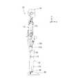
以下添付図面に基づいて、本発明の第一の実施形態におけるロボットの関節構造を説明する。図1は、ロボットの関節構造が組み込まれた人間型ロボットの全体構成を示す正面図である。図2は人間型ロボットの右側面図である。本実施形態において左右は図に示す人間型ロボット側から見た左右である。 The robot joint structure according to the first embodiment of the present invention will be described below with reference to the accompanying drawings. FIG. 1 is a front view showing an overall configuration of a humanoid robot in which a robot joint structure is incorporated. FIG. 2 is a right side view of the humanoid robot. In the present embodiment, the left and right are the left and right viewed from the humanoid robot side shown in the figure.
人間型ロボット10は、胴体部11の下方に設置された二本の脚部12と、胴体部11の上方左右両側面に設置された二本の腕部13と、胴体部11の上方に設置された一個の頭部14とから構成されており、人間に近い動作を可能としている。 The
二本の腕部13は、胴体部11の周囲で自在に移動できるようになっている。各腕部13は肘を境に、肩に近い方の上腕部13cと、手部13aに近い方の下腕部13bと、を備える。下腕部13bの先端には手首関節21を介して手部13aが設置されている。手部13aを利用することで物を掴んだり摘まんだりすることが可能となっている。 The two
この人間型ロボット10は、二足歩行ロボットであり、人間のように二本脚でバランスをとりながら歩く。各脚部12は股関節16を介して胴体部11の骨盤に連結されている。股関節16は各脚部12をヨー軸、ピッチ軸、及びロール軸回りに回転させる。ここで、人間型ロボットの進行方向をx軸正方向、ロボットからみて左手方向をy軸正方向、ロボットの上方をz軸方向としたとき、x軸がロール軸、y軸がピッチ軸、z軸がヨー軸である。そして、x軸回りの回転がロール、y軸回りの回転がピッチ、z軸回りの回転がヨーである。 The
股関節16には大腿部17aが連結される。大腿部17aの下には膝関節18が設けられる。膝関節18の下には脛部17bが連結される。脛部17bの下には足首関節19が設けられる。足首関節19の下には歩行路面と接触する足部20が連結される。 A
頭部14および胴体部11には、それぞれにCCDカメラ15が設置されている。このCCDカメラ15によって、人間型ロボット10の周囲の状況を画像データとして収集することが可能となっている。 A
この人間型ロボット10は、遠隔操作可能に構成されたロボットであり、離れた位置にある図示しない操作マニピュレータを操作者が操作することで、操作マニピュレータの動きに応じた動作を人間型ロボット10が実行できるようになっている。したがって、操作者は、インターネット回線等の無線通信手段や人間型ロボット10に設置されたCCDカメラ15等を介して、遠隔地に居ながらにして人間型ロボット10の周囲の状況を把握でき、人間型ロボット10の操作ができるようになっている。 This
図3は、本発明の第一の実施形態のロボットの関節構造が組み込まれたロボットの手首関節の斜視図を示す。この実施形態のロボットの関節構造は、下腕部13bと手部13aとの間の手首関節21に組み込まれる。この実施形態のロボットの関節構造は、第一部材としての下腕部フレーム22、第二部材としての可動フレーム23、下腕部フレーム22と可動フレーム23とを回転可能に連結する自在継手24、第一及び第二のアーム25a,25b、第一及び第二の中間リンク26a,26b、第一及び第二のアクチュエータとしての第一及び第二の直動アクチュエータ28a,28bと、を備ええる。 FIG. 3 is a perspective view of the wrist joint of the robot incorporating the joint structure of the robot according to the first embodiment of the present invention. The joint structure of the robot of this embodiment is incorporated into the wrist joint 21 between the
可動フレーム23は下腕部フレーム22に対して直角な二軸の回りを回転可能であり、2自由度を持つ。下腕部フレーム22には、人間の筋肉のように機能する第一及び第二の直動アクチュエータ28a,28bが平行に収納される。第一及び第二の直動アクチュエータ28a,28bが押し引き動作を行うことによって、可動フレーム23が直角な二軸の回りを回転する。 The
可動フレーム23には手部13aが固定されている。手部13aには複数本の指27a〜27cが設けられている。複数本の指27a〜27cは物を掴んだり摘まんだりすることができるように曲げることが可能となっている。 A
図4は、関節構造の詳細図を示す。図4(a)は関節構造の側面図を示し、図4(b)及び図4(c)は図3と同方向から見た斜視図を示す。図4(b)は第一及び第二の直動アクチュエータ28a,28bが軸部31a,31bを同方向に引き込んだ状態を示し、図4(c)は第一及び第二の直動アクチュエータ28a,28bが軸部31a,31bを異なった方向に押し引きしている状態を示す。 FIG. 4 shows a detailed view of the joint structure. 4A shows a side view of the joint structure, and FIGS. 4B and 4C show perspective views as seen from the same direction as FIG. 4B shows a state in which the first and second
図4(b)に示すように、第一及び第二の直動アクチュエータ28a,28bが軸部31a,31bを同方向に引き込むと、可動フレーム23がピッチ軸の回りを回転するようになっている。図4(c)に示すように、第一及び第二の直動アクチュエータ28a,28bが軸部31a,31bを異なった方向に押し引きすると、可動フレーム23がヨー軸の回りを回転するようになっている。ここでは、図4(a)に示すように、下腕部フレーム22の長さ方向をx軸正方向、図4(a)の上方向をy軸正方向、図4(a)の紙面と直交する方向をz軸方向としていて、x軸をロール軸、y軸をピッチ軸、z軸をヨー軸としている。図4(b)では可動フレーム23がピッチ軸(自在継手24のピッチ軸部24a)の回りを回転していて、図4(c)では可動フレーム23がヨー軸(自在継手24のヨー軸部24b)の回りを回転している。 As shown in FIG. 4B, when the first and second
下腕部フレーム22は、下腕部13bの長さ方向に伸びる互いに平行な一対の対向プレート22a,22bを備える。対向プレート22a,22bは長さ方向の端部の連結プレートに一体的に結合される。一対の対向プレート22a,22b間には、第一及び第二の直動アクチュエータ28a,28bが略平行に収容される。 The lower
可動フレーム23は、手部13aが取り付けられる取付プレート23aと、取付プレート23aに対して直角に折り曲げられ、互いに平行な一対の支持プレート23b,23cと、を備える。 The
下腕部フレーム22の先端には、自在継手24としての十文字状の軸体24が取り付けられる。軸体24は、直角な二軸を構成するピッチ軸部24a及びヨー軸部24bを備える。この実施形態では、ピッチ軸部24a及びヨー軸部24bの軸線が平面内で直交している。ヨー軸部24bは一対の対向プレート22a,22b間に架け渡され、一対の対向プレート22a,22bに回転可能に支持される。ピッチ軸部24aは可動フレーム23の一対の支持プレート23b,23c間に架け渡され、一対の支持プレート23b,23cに回転可能に連結される。下腕部フレーム22に軸体24がヨー軸部24bの回りを回転可能に支持され、軸体24には可動フレーム23がピッチ軸部24aの回りを回転可能に連結されるので、下腕部フレーム22に対して可動フレーム23が直交するピッチ軸部24a及びヨー軸部24bの回りを回転可能となっている。なお、ピッチ軸部24aとヨー軸部24bの軸線は直角を保てればよく、直交せずに離間していてもよい。 A
第一及び第二の直動アクチュエータ28a,28bそれぞれは、円筒状の本体部32a,32bと、本体部32a,32bに対して軸線方向に直線運動する軸部31a,31bと、を備える。第一及び第二の直動アクチュエータ28a,28bの構造は同一である。軸部31a,31bは本体部32a,32bの軸線上に配置される。軸部31a,31bの外周面には螺旋状のねじ溝が形成される。本体部32a,32bには、軸部31a,31bのねじ溝に螺合するボールねじナット(図示せず)が収納される。本体部32a,32bには、ボールねじナットが本体部32a,32bに軸線の回りの回転のみが許容された状態で収納される。本体部32a,32bにはさらにボールねじナットを回転させるサーボモータが収納される。サーボモータがボールねじナットを回転させると、ボールねじナットの軸線方向の移動が制限されているので、軸部31a,31bが軸線方向に直線運動する。 Each of the first and second
第一及び第二の直動アクチュエータ28a,28bの本体部32a,32bは、下腕部フレーム22に回転可能に支持される。本体部32a,32bは四角形の枠部35a,35b(図4(a)参照)に嵌められている。四角形の枠部35a,35bは回転軸36a,36b(図4(a)参照)を備え、下腕部フレーム22に回転可能に支持される。第一及び第二の直動アクチュエータ28a,28bの本体部32a,32bは回転軸36a,36bを中心として揺動することが可能となっている。回転軸36a,36bは軸体24のヨー軸部24bと平行である。第一及び第二の直動アクチュエータ28a,28bは上下方向に二つ配列されていて、回転軸36a,36bも上下方向に二つ設けられる。 The
第一及び第二の直動アクチュエータ28a,28bと軸体24との間には、第一及び第二の中間リンク26a,26bが回転可能に設けられる。第一及び第二の中間リンク26a,26bは別々に回転可能である。第一の中間リンク26aは第一の軸線26a1(図4(a)参照)の回りを回転可能であり、第二の中間リンク26bは第二の軸線26b1(図4(a)参照)の回りを回転可能である。この実施形態では、第一の軸線26a1及び第二の軸線26b1が同一の直線L(図4(b)参照)上に配置され、第一及び第二の中間リンク26a,26bは共通の直線Lの回りを回転する。第一及び第二の中間リンク26a,26bを回転可能に支持する回転軸は一対の対向プレート22a,22b間に架け渡され、軸体24のヨー軸部24bと平行である。 Between the first and second
図4(b)に示すように、第一及び第二の中間リンク26a,26bそれぞれは、回転軸に回転可能に支持される基部26a2,26b2と、基部26a2,26b2から二股に分岐するブラケット部26a3,26b3と、ブラケット部26a3,26b3に回転可能に支持される連結軸26a4,26b4と、を備える。基部26a2,26b2は、一対の対向プレート22a,22b間に収納できるように一対の対向プレート22a,22b間の距離の半分の軸線方向長さを持つ。ブラケット部26a3,26b3は、連結軸26a4,26b4を回転可能に支持する。ブラケット部26a3,26b3は、一対の対向プレート22a,22b間の略全長に渡る横幅を有する。第一及び第二の中間リンク26a,26bのなす角度が所定角度、例えば90度以下になるときは、第一の中間リンク26aのブラケット部26a3と第二の中間リンク26bのブラケット部26b3とが当接し、第一の中間リンク26aと第二の中間リンク26bとのなす角度が所定角度以下になるのを制限している。連結軸26a4,26b4には、第一及び第二の直動アクチュエータ28a,28bの軸部31a,31bの先端が結合される。 As shown in FIG. 4B, each of the first and second
可動フレーム23と第一の中間リンク26aとの間には第一のアーム25aが架け渡される。第一のアーム25aの長さ方向の両端部にはボールジョイントが設けられ、第一のアーム25aはボールジョイントを介して可動フレーム23及び第一の中間リンク26aの連結軸26a4に連結される。図5は第一のアーム25aの端部に組み込まれるボールジョイント41の断面図を示す。ボールジョイント41は3自由度の継手であり、例えば内輪41b及び外輪41aを球面接触させた構造の球面軸受から構成される。外輪41aは第一のアーム25aに結合される。内輪41bには可動フレーム23から突出する軸体42が結合される。内輪41bは外輪41aに対して直交する三軸の回りを回転可能である。ボールジョイントとして、例えばリンクボール(THK社製品名)継手を用いることができる。 A
図4(b)に示すように、可動フレーム23と第二の中間リンク26bとの間には第二のアーム25bが架け渡される。第二のアーム25bの長さ方向の両端部には、第一のアーム25aと同一のボールジョイントが設けられる。第二のアーム25bはボールジョイントを介して可動フレーム23及び第二の中間リンク26bの連結軸26b4に連結される。 As shown in FIG. 4B, the
下腕部フレーム22の対向プレート22a,22b間には、第一及び第二の直動アクチュエータ28a,28bに隣接して、第一及び第二の直動アクチュエータ28a,28bのサーボモータを制御する第一及び第二のドライバ34a,34bが設けられる。第一及び第二のドライバ34a,34bのそれぞれは、サーボモータに電力を供給するPWM(pulse width modulation)インバータ等の電力変換器、サーボモータの出力軸の速度及び位置を検出するセンサ、操作マニピュレータからの指令及びセンサからの情報によって電力変換器を制御する制御器を備える。第一及び第二のドライバ34a,34bは相互に通信し合い、別に制御ボックスが無くても同期した動きが可能となっている。なお、第一及び第二のドライバ34a,34bを統合させた一つのドライバによって二つのサーボモータを制御するようにしてもよい。 Between the opposing
図4(b)に示すように、第一及び第二のドライバ34a,34bに指令を与え、第一及び第二の直動アクチュエータ28a,28bが軸部31a,31bを同方向に引き込むようにすると、第一の中間リンク26a及び第二の中間リンク26bが互いに反対方向に回転する。この例では、上側の第一の中間リンク26aが時計方向に回転し、下側の第二の中間リンク26bが反時計方向に回転する。第一及び第二の中間リンク26a,26bが互いに反対方向に回転すると、第一及び第二のアーム25a,25bが引き込まれ、第一及び第二のアーム25a,25bに連結される可動フレーム23がピッチ軸部24aの回りのみを回転する。逆に、第一及び第二の直動アクチュエータ28a,28bが軸部31a,31bを同方向に押し出すようにすると、可動フレーム23はピッチ軸部24aの回りのみを反対方向に回転する。 As shown in FIG. 4B, a command is given to the first and
図4(c)に示すように、第一及び第二のドライバ34a,34bに指令を与え、第一の直動アクチュエータ28aが軸部31aを押し出し、第二の直動アクチュエータ28bが軸部31bを引き込むようにすると、第一及び第二の中間リンク26a,26bが同方向に回転する。この例では、上側の第一の中間リンク26a及び下側の第二の中間リンク26bのいずれもが反時計方向に回転する。第一及び第二の中間リンク26a,26bが反時計方向に回転すると、第一のアーム25aが押し出され、第二のアーム25bが引き込まれる。これにより第一及び第二のアーム25a,25bに連結される可動フレーム23がヨー軸部24bの回りのみを回転する。逆に、第一の直動アクチュエータ28aが軸部31aを引き込み、第二の直動アクチュエータ28bが軸部31bを押し出すようにすると、可動フレーム23がヨー軸部24bの回りのみを反対方向に回転する。 As shown in FIG. 4C, a command is given to the first and
なお、図4(b)及び図4(c)では、可動フレーム23をピッチ軸部24aの回りにのみ又はヨー軸部24b回りにのみ回転させる例について説明したが、可動フレーム23をピッチ軸部24aの回りに回転させながらヨー軸部24bの回りに回転させることも可能となっている。 In FIGS. 4B and 4C, the example in which the
この第一の実施形態のロボットの関節構造によれば、以下の効果を奏する。可動フレーム23を直角な二軸の回りに回転させるにあたって第一及び第二の直動アクチュエータ28a,28bを同時に作動させている。このため、従来の回転系のサーボモータを組み合わせた関節構造に比べて、力を数倍発生することができる。逆にいえば、必要な力を得るための第一及び第二の直動アクチュエータ28a,28bを小型化することができ、関節構造の小型化が図れる。 The joint structure of the robot according to the first embodiment has the following effects. The first and second
第一及び第二の中間リンク26a,26bを反対方向に回転させることによって、可動フレーム23をピッチ軸部24aの回りに回転させている。そして、第一及び第二の中間リンク26a,26bを反対対方向に回転させることによって、可動フレーム23をヨー軸部24bの回りに回転させている。第一及び第二の中間リンク26a,26bの回転と可動フレーム23のピッチ軸部24a及びヨー軸部24bの回転との因果関係が理解し易いので、第一及び第二の直動アクチュエータ28a,28bの制御が容易になる。 By rotating the first and second
第一及び第二のアーム25a,25bと第一及び第二の直動アクチュエータ28a,28bとの間には、第一及び第二の中間リンク26a,26bが介在し、可動フレーム23に作用する荷重は一旦第一及び第二の中間リンク26a,26bが受ける。このため、可動フレーム23に作用する荷重が第一及び第二の直動アクチュエータ28a,28bの軸部31a,31bに直接的に作用するのを防止でき、軸部31a,31bに軸線方向以外のラジアル荷重、ねじれ、モーメント等の無理な力が作用するのを防止できる。 First and second
第一及び第二のアーム25a,25bの長さ方向の両端部には、3自由度のボールジョイントが設けられる。このため、可動フレーム23がピッチ軸部24a及びヨー軸部24bの回りを回転しても、可動フレーム23から第一及び第二の中間リンク26a,26bに無理な力がかかるのを防止できる。 A ball joint having three degrees of freedom is provided at both ends in the length direction of the first and
第一及び第二の直動アクチュエータ28a,28bの本体部32a,32bは下腕部フレーム22に回転可能に支持され、第一及び第二の直動アクチュエータ28a,28bの軸部31a,31bは第一及び第二の中間リンク26a,26bに回転可能に連結されている。このため、第一及び第二の直動アクチュエータ28a,28bの軸部31a,31bが軸線方向に移動すると、第一及び第二の直動アクチュエータ28a,28bが回転軸36a,36bの回りを揺動する。このため、第一及び第二の中間リンク26a,26bが回転しても、第一及び第二の直動アクチュエータ28a,28bの軸部31a,31bに軸線方向以外のラジアル荷重、ねじれ、モーメント等の無理な力が作用するのを防止できる。 The
第一の中間リンク26aと第二の中間リンク26bとのなす角度が所定角度のとき、第一の中間リンク26aと第二の中間リンク26bとが互いに当接する。第一の中間リンク26aと第二の中間リンク26bとをストッパとして機能させることで、第一及び第二の直動アクチュエータ28a,28bに供給する電力が切れても、可動フレーム23の回転角度を一定に保つことができる。 When the angle formed by the first
下腕部フレーム22に第一及び第二の直動アクチュエータ28a,28bを制御する第一及び第二のドライバ34a,34bを設けることで、第一及び第二のアクチュエータ28a,28bの同期した動作が容易になる。また、配線を省略すること可能になる。 By providing the first and
自在継手としての軸体24が平面内で直交するピッチ軸部24a及びヨー軸部24bを備えるので、可動フレーム23を下腕部フレーム22に対して直交する二軸の回りを回転させることが可能になる。ただし、ピッチ軸部24aとヨー軸部24bとは直角であればよく、平面内で直交せずに離間していてもよい。 Since the
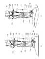
図6は、本発明の第二の実施形態のロボットの関節構造が組み込まれたロボットの足首関節を示す。この実施形態のロボットの関節構造は人間型ロボット10の足首関節19(図1参照)に適用されている。この実施形態のロボットの関節構造の基本構造は、上記第一の実施形態のロボットの関節構造と同一であり、第一及び第二のアーム51a,51b、第一及び第二の中間リンク52a,52b、第一及び第二の直動アクチュエータ53a,53bを備える。第一及び第二の直動アクチュエータ53a,53bを動作させることによって、脛部リンク54に対して足部フレーム55をピッチ軸及びロール軸の回りに回転させる。 FIG. 6 shows an ankle joint of a robot in which the joint structure of the robot according to the second embodiment of the present invention is incorporated. The joint structure of the robot of this embodiment is applied to the ankle joint 19 (see FIG. 1) of the
脛部リンク54の下端には、自在継手として、ピッチ軸部56a及びロール軸部56bを備える十文字状の軸体56が設けられる。軸体56のピッチ軸部56aは脛部リンク54に回転可能に取り付けられる。軸体56のロール軸部56bは足部フレーム55に回転可能に取り付けられる。足部フレーム55は脛部リンク54に対してピッチ軸部56a及びロール軸部56bの回りに回転可能になっている。 A
脛部リンク54を挟んで図中奥側には第一の直動アクチュエータ53a、第一の中間リンク52a及び第一のアーム51aが配置される。手前側には第二の直動アクチュエータ53b、第二の中間リンク52b及び第二のアーム51bが配置される。 A first
第一及び第二の直動アクチュエータ53a,53bは、直方体状の本体部61と、本体部61に対して軸線方向に直線運動する軸部62と、を備える。第一及び第二の直動アクチュエータ53a,53bの構造は同一である。本体部61の外形形状は第一の実施形態と異なるが、基本構造は第一の実施形態と同一である。本体部61の内部には、サーボモータ、及びサーボモータによって回転駆動されるボールねじナットが設けられる。軸部62の外周面には螺旋状のねじ溝が形成される。サーボモータがボールねじナットを回転駆動すると、ボールねじナットに螺合する軸部62が軸線方向に直線運動する。 The first and second
第一及び第二の直動アクチュエータ53a,53bは、脛部リンク54にピッチ軸の回りを回転可能に支持される。脛部リンク54には枠状のホルダ63が固定される。枠状のホルダ63には第一及び第二の直動アクチュエータ53a,53bの回転軸64が回転可能に嵌められる。第一及び第二の直動アクチュエータ53a,53bの回転軸64は同一の直線上に配置される。 The first and second
脛部リンク54の、第一及び第二の直動アクチュエータ53a,53bの下側には、第一及び第二の中間リンク52a,52bが回転可能に支持される。第一及び第二の中間リンク52a,52bは、ピッチ軸と平行な軸線の回りを回転可能である。第一の中間リンク52aの軸線と第二の中間リンク52bの軸線は同一の直線L上に配置される。第一及び第二の中間リンク52a,52bのそれぞれは、基部68と、基部68から二股状に分岐するブラケット部69と、を備える(図6(a)参照)。ブラケット部69には連結軸67が回転可能に支持される。連結軸67はピッチ軸に平行である。第一及び第二の直動アクチュエータ53a,53bの軸部62の先端は連結軸67に固定されている。 The first and second
第一及び第二の中間リンク52a,52bと足部フレーム55とは第一及び第二のアーム51a,51bを介して連結される。第一及び第二のアーム51a,51bの上端部はボールジョイントを介して第一及び第二の中間リンク52a,52bの連結軸67に連結される。第一及び第二のアーム51a,51bの下端部はボールジョイントを介して足部フレーム55に連結される。第一及び第二のアーム51a,51bと足部フレーム55との連結位置は、軸体56のピッチ軸部56a及びロール軸部56bの軸線からずれた位置になっている。 The first and second
図6(a)に示すように、第一及び第二の直動アクチュエータ53a,53bが第一及び第二の中間リンク52a,52bを同方向に回転させると、第一及び第二のアーム51a,51bに連結される足部フレーム55がピッチ軸部56aの回りを回転する。 As shown in FIG. 6A, when the first and second
図6(b)に示すように、第一及び第二の直動アクチュエータ53a,53bが第一及び第二の中間リンク52a,52bを反対方向に回転させると、第一及び第二のアーム51a,51bに連結される足部フレーム55がロール軸部56bの回りを回転する。 As shown in FIG. 6B, when the first and second
図7は、本発明の第三の実施形態のロボットの関節構造の斜視図を示す。この実施形態のロボットの関節構造は人間型ロボット10の股関節16に組み込まれる。図8はロボットの関節構造の側面図を示す。図8(a)は大腿部リンク64を真っすぐにした状態を示し、図8(b)は脚部12の足踏み動作を実行するために大腿部リンク64を曲げた状態を示す。股関節フレーム65に対して大腿部リンク64をピッチ軸部66a及びロール軸部66bの回りに回転させることで、脚部12の足踏み動作が可能になる。脚部12の方向転換は股関節フレーム65をヨー軸65aの回りに回転させることで可能になる。 FIG. 7 is a perspective view of the joint structure of the robot according to the third embodiment of the present invention. The joint structure of the robot of this embodiment is incorporated in the
図7に示すように、第三の実施形態のロボットの関節構造も、第一及び第二の直動アクチュエータ53a,53b、第一及び第二の中間リンク52a,52b、第一及び第二のアーム51a,51bを備える。図7の大腿部リンク64を図6の脛部リンク54と看做し、図7の股関節フレーム65を図6の足部フレーム55と看做すと、第三の実施形態のロボットの関節構造は第二の実施形態のロボットの関節構造と略同一である。図7を上下反転させると、図6に示すロボットの関節構造に近づくのがわかる。ここでは、重複した説明を避けるために、図6に示す第二の実施形態のロボットの関節構造と同一の構成については同一の符号を付してその説明を省略する。 As shown in FIG. 7, the joint structure of the robot of the third embodiment also includes the first and second
図8に示すように、この実施形態では、第一及び第二の中間リンク52a,52b(図8では52bのみを示す)は、共通の軸線Lよりも連結軸67とは反対方向に延設されている。この第一及び第二の中間リンク52a,52bの延設された部分にはばね取付部71が設けられる。第一及び第二の中間リンク52a,52bには、共通の軸線Lを挟んで一方の側に連結軸67が設けられ、他方の側にばね取付部71が設けられる。このばね取付部71にコイルばね72の一端が掛けられる。コイルばね72の他端は大腿部リンク64に固定されたばね支持部73に掛けられる。コイルばね72は引っ張りばねであり、第一及び第二の中間リンク52a,52bが回転しても常に引っ張り力を発生する長さに設定される。 As shown in FIG. 8, in this embodiment, the first and second
図8(a)及び図8(b)に示すように、第一及び第二の直動アクチュエータ53a,53bが軸部62を同時に引き込むと、第一及び第二の中間リンク52a,52bが軸線Lの回りを反時計方向に回転し、大腿部リンク64が持ち上がる。大腿部リンク64が持ち上がると、コイルばね72はより大きな引っ張り力を発生し、第一及び第二の中間リンク52a,52bに復元するようなトルクを付与する。このため、図8(b)の状態から図8(a)の状態に戻すときに、第一及び第二の直動アクチュエータ53a,53bにかかる負荷を低減させ、サーボモータの負荷を軽くすることが可能になる。また、コイルばね72は、図8(a)に示すように、大腿部リンク64が真っすぐの状態に戻そうとするので、第一及び第二の直動アクチュエータ53a,53bの電源が切れても、ロボットを図1に示す直立した状態に安定的に保つことが可能になる。 As shown in FIGS. 8A and 8B, when the first and second
第三の実施形態のロボットの関節構造によれば、第一及び第二の中間リンク52a,52bと大腿部リンク64との間にばねを介在し、自重をキャンセルするので、第一及び第二の直動アクチュエータ53a,53bの負荷が低減し、小さな電力、小さい第一及び第二の直動アクチュエータ53a,53bを使用することが可能になる。 According to the joint structure of the robot of the third embodiment, a spring is interposed between the first and second
本実施形態のような重力キャンセル用のコイルばね72を設ける場合には、大腿部リンク64と股関節フレーム65との間に架け渡すのが一般的である。しかし、大腿部リンク64は股関節フレーム65に対して2自由度を持つ。このため、大腿部リンク64と股関節フレーム65との間にコイルばね72に架け渡すと、コイルばね72が周囲に飛び出したり、他の構造物に当たったりするおそれがある。大腿部リンクと第一及び第二の中間リンク52a,52bとの間にコイルばね72を架け渡すことによって、コイルばね72の収まりもよくなる。 When the
なお、本発明は上記実施形態に具現化されるのに限られることはなく、本発明の要旨を変更しない範囲で様々に変更可能である。 The present invention is not limited to being embodied in the above-described embodiment, and can be variously modified without changing the gist of the present invention.
上記実施形態では、本発明のロボットの関節構造を、手首関節、足首関節、股関節に適用した例について説明したが、首関節、肩関節、上体を前傾や後傾させる腰の関節等の他の関節にも適用することができる。 In the above-described embodiment, an example in which the joint structure of the robot of the present invention is applied to a wrist joint, an ankle joint, and a hip joint has been described. It can also be applied to other joints.
本発明は人間型ロボットに限られることはなく、垂直多関節ロボット、水平多関節ロボット等の産業用ロボットに適用することができる。 The present invention is not limited to a humanoid robot, and can be applied to industrial robots such as vertical articulated robots and horizontal articulated robots.
本発明は2自由度の関節構造に限られることはなく、第三の中間リンク、第三のアーム、第三のアクチュエータ等を付加することで、自由度が3以上の関節構造にも適用することができる。 The present invention is not limited to a joint structure with two degrees of freedom, and can be applied to a joint structure with three or more degrees of freedom by adding a third intermediate link, a third arm, a third actuator, or the like. be able to.
第一及び第二のアクチュエータは、第一及び第二の中間リンクを回転させることができれば、上記実施形態の直動アクチュエータに限られることはなく、回転運動を直線運動に変換する種々のものを使用することができる。 The first and second actuators are not limited to the linear motion actuators of the above embodiment as long as the first and second intermediate links can be rotated, and various actuators that convert rotational motion into linear motion can be used. Can be used.
上記実施形態では、第一及び第二のアーム、第一及び第二の中間リンクの一例について説明したが、これらの形状、構造は上記実施形態に限られることはなく、本発明の要旨を変更しない範囲で様々に変更可能である。 In the said embodiment, although an example of the 1st and 2nd arm and the 1st and 2nd intermediate link was demonstrated, these shapes and structures are not restricted to the said embodiment, The summary of this invention is changed. Various changes can be made without departing from the scope.
22…下腕部フレーム(第一部材),23…可動フレーム(第二部材),24…軸体(自在継手),24a…ピッチ軸部,24b…ヨー軸部,25a,25b…第一及び第二のアーム,26a,26b…第一及び第二の中間リンク,26a1…第一の軸線,26b1…第二の軸線,28a,28b…第一及び第二の直動アクチュエータ,31a,31b…第一及び第二の直動アクチュエータの軸部,32a,32b…第一及び第二の直動アクチュエータの本体部,34a,34b…第一及び第二のドライバ,41…ボールジョイント,51a,51b…第一及び第二のアーム,52a,52b…第一及び第二の中間リンク,53a,53b…第一及び第二の直動アクチュエータ,54…脛部リンク(第一部材),55…足部フレーム(第二部材),56…軸体(自在継手),56a…ピッチ軸部,56b…ロール軸部,61…第一及び第二の直動アクチュエータの本体部,62…第一及び第二の直動アクチュエータの軸部,64…大腿部リンク(第一部材),65…股関節フレーム(第二部材),66…軸体(自在継手),66a…ピッチ軸部,66b…ロール軸部,72…コイルばね(ばね)
22 ... Lower arm frame (first member), 23 ... Movable frame (second member), 24 ... Shaft (universal joint), 24a ... Pitch shaft, 24b ... Yaw shaft, 25a, 25b ... First and Second arm, 26a, 26b ... first and second intermediate links, 26a1, ... first axis, 26b1, ... second axis, 28a, 28b ... first and second linear actuators, 31a, 31b ... Shaft portions of first and second linear actuators, 32a, 32b, main body portions of first and second linear actuators, 34a, 34b, first and second drivers, 41, ball joints, 51a, 51b ... first and second arms, 52a, 52b ... first and second intermediate links, 53a, 53b ... first and second linear actuators, 54 ... shin link (first member), 55 ... foot Part frame (second part ), 56... Shaft body (universal joint), 56 a... Pitch shaft portion, 56 b... Roll shaft portion, 61... Main body portion of the first and second linear actuators, 62. Shaft part, 64 ... thigh link (first member), 65 ... hip joint frame (second member), 66 ... shaft body (universal joint), 66a ... pitch shaft part, 66b ... roll shaft part, 72 ... coil spring (Spring)
Claims (7)
Translated fromJapanese前記第一部材に第一の軸線の回りを回転可能に支持される第一の中間リンクと、
一端が前記第二部材にボールジョイントを介して連結されると共に、他端が前記第一の中間リンクにボールジョイントを介して連結される第一のアームと、
前記第一の中間リンクを前記第一の軸線の回りに回転させる第一のアクチュエータと、
前記第一部材に第二の軸線の回りを回転可能に支持される第二の中間リンクと、
一端が前記第二部材にボールジョイントを介して連結されると共に、他端が前記第二の中間リンクにボールジョイントを介して連結される第二のアームと、
前記第二の中間リンクを前記第二の軸線の回りに回転させる第二のアクチュエータと、
を備え、
前記第一の中間リンクの前記第一の軸線及び前記第二の中間リンクの前記第二の軸線が同一の直線上に配置され、
前記第一及び前記第二のアクチュエータは、本体部と、外周面に螺旋状のねじ溝が形成される軸部と、前記本体部に収納され、前記軸部のねじ溝に螺合するナットと、を備え、前記ナットを回転させると、前記本体部に対して前記軸部が直線運動する直動アクチュエータであり、
前記第一及び前記第二のアクチュエータの前記本体部が、前記第一部材に回転可能に支持され、
前記第一及び前記第二のアクチュエータの前記軸部の先端が、前記第一及び前記第二の中間リンクのブラケット部に回転可能に支持される連結軸に固定されるロボットの関節構造。In the joint structure of the robot in which the second member is rotated relative to the first member around two axes perpendicular to each other,
A first intermediate link supported by the first member so as to be rotatable about a first axis;
A first arm having one end connected to the second member via a ball joint and the other end connected to the first intermediate link via a ball joint;
A first actuator for rotating the first intermediate link about the first axis;
A second intermediate link rotatably supported about the second axis by the first member;
A second arm having one end connected to the second member via a ball joint and the other end connected to the second intermediate link via a ball joint;
A second actuator for rotating the second intermediate link about the second axis;
With
It said first of said second axis of said first axis and said second intermediate link of the intermediate links are disposed on the same straightline,
The first and second actuators include a main body portion, a shaft portion in which a spiral thread groove is formed on an outer peripheral surface, a nut that is housed in the main body portion and is screwed into the screw groove of the shaft portion, When the nut is rotated, the shaft portion linearly moves with respect to the main body portion.
The main body portions of the first and second actuators are rotatably supported by the first member,
A joint structure ofa robotin which tips of the shaft portions of the first and second actuators are fixed to a connecting shaft that is rotatably supported by bracket portions of the first and second intermediate links .
前記第一及び前記第二のアクチュエータが前記第一及び前記第二の中間リンクを互いに反対方向に回転させることによって、前記第二部材が前記第一部材に対して前記直角な二軸のうちの他方の軸の回りを相対的に回転することを特徴とする請求項1に記載のロボットの関節構造。The first and second actuators rotate the first and second intermediate links in the same direction so that the second member is out of the two axes perpendicular to the first member. Rotate relatively around one axis,
The first and second actuators rotate the first and second intermediate links in opposite directions so that the second member is out of the two axes perpendicular to the first member. The robot joint structure according to claim 1, wherein the robot joint rotates relatively around the other axis.
前記第一部材に第一の軸線の回りを回転可能に支持される第一の中間リンクと、
一端が前記第二部材にボールジョイントを介して連結されると共に、他端が前記第一の中間リンクにボールジョイントを介して連結される第一のアームと、
前記第一の中間リンクを前記第一の軸線の回りに回転させる第一のアクチュエータと、
前記第一部材に第二の軸線の回りを回転可能に支持される第二の中間リンクと、
一端が前記第二部材にボールジョイントを介して連結されると共に、他端が前記第二の中間リンクにボールジョイントを介して連結される第二のアームと、
前記第二の中間リンクを前記第二の軸線の回りに回転させる第二のアクチュエータと、
を備え、
前記第一の中間リンクの前記第一の軸線及び前記第二の中間リンクの前記第二の軸線が同一の直線上に配置され、
前記第一及び前記第二のアクチュエータが前記第一及び前記第二の中間リンクを互いに同方向に回転させることによって、前記第二部材が前記第一部材に対して前記直角な二軸のうちの一方の軸の回りを相対的に回転し、
前記第一及び前記第二のアクチュエータが前記第一及び前記第二の中間リンクを互いに反対方向に回転させることによって、前記第二部材が前記第一部材に対して前記直角な二軸のうちの他方の軸の回りを相対的に回転し、
前記第一の中間リンクと前記第二の中間リンクとのなす角度が所定角度以下になるのを制限するように、前記第一の中間リンクと前記第二の中間リンクとのなす角度が前記所定角度のとき、前記第一の中間リンクと前記第二の中間リンクとが互いに当接するロボットの関節構造。In the joint structure of the robot in which the second member is rotated relative to the first member around two axes perpendicular to each other,
A first intermediate link supported by the first member so as to be rotatable about a first axis;
A first arm having one end connected to the second member via a ball joint and the other end connected to the first intermediate link via a ball joint;
A first actuator for rotating the first intermediate link about the first axis;
A second intermediate link rotatably supported about the second axis by the first member;
A second arm having one end connected to the second member via a ball joint and the other end connected to the second intermediate link via a ball joint;
A second actuator for rotating the second intermediate link about the second axis;
With
The first axis of the first intermediate link and the second axis of the second intermediate link are arranged on the same straight line;
The first and second actuators rotate the first and second intermediate links in the same direction so that the second member is out of the two axes perpendicular to the first member. Rotate relatively around one axis,
The first and second actuators rotate the first and second intermediate links in opposite directions so that the second member is out of the two axes perpendicular to the first member. Rotate relatively around the other axis,
The angle formed between the first intermediate link and the second intermediate link is limited to the predetermined angle so that the angle formed between the first intermediate link and the second intermediate link is less than or equal to a predetermined angle. A joint structure of a robot in which the first intermediate link and the second intermediate link are in contact with each other at an angle.
前記第一部材が前記直交する二軸のうちの一方の軸に回転可能に連結され、前記第二部材が前記直交する二軸のうちの他方の軸に回転可能に連結されることを特徴とする請求項1ないし4のいずれかに記載のロボットの関節構造。The first member and the second member are connected via a joint having two axes perpendicular to each other in a plane,
The first member is rotatably connected to one of the two orthogonal axes, and the second member is rotatably connected to the other of the two orthogonal axes. The robot joint structure according to any one of claims 1 to4 .
Priority Applications (4)
| Application Number | Priority Date | Filing Date | Title |
|---|---|---|---|
| JP2011233250AJP5722747B2 (en) | 2011-10-24 | 2011-10-24 | Robot joint structure and robot incorporating this joint structure |
| US14/352,521US9375851B2 (en) | 2011-10-24 | 2012-10-19 | Articular structure for robot and robot with incorporated articular structure |
| PCT/JP2012/077043WO2013061868A1 (en) | 2011-10-24 | 2012-10-19 | Articular structure for robot and robot with incorporated articular structure |
| TW101139190ATWI522217B (en) | 2011-10-24 | 2012-10-24 | Joint structure of robot and robot having the same incorporated therein |
Applications Claiming Priority (1)
| Application Number | Priority Date | Filing Date | Title |
|---|---|---|---|
| JP2011233250AJP5722747B2 (en) | 2011-10-24 | 2011-10-24 | Robot joint structure and robot incorporating this joint structure |
Publications (2)
| Publication Number | Publication Date |
|---|---|
| JP2013091122A JP2013091122A (en) | 2013-05-16 |
| JP5722747B2true JP5722747B2 (en) | 2015-05-27 |
Family
ID=48167700
Family Applications (1)
| Application Number | Title | Priority Date | Filing Date |
|---|---|---|---|
| JP2011233250AActiveJP5722747B2 (en) | 2011-10-24 | 2011-10-24 | Robot joint structure and robot incorporating this joint structure |
Country Status (4)
| Country | Link |
|---|---|
| US (1) | US9375851B2 (en) |
| JP (1) | JP5722747B2 (en) |
| TW (1) | TWI522217B (en) |
| WO (1) | WO2013061868A1 (en) |
Families Citing this family (20)
| Publication number | Priority date | Publication date | Assignee | Title |
|---|---|---|---|---|
| JP6087329B2 (en)* | 2014-09-19 | 2017-03-01 | Thk株式会社 | Rotation drive mechanism in robot |
| JP6105024B2 (en)* | 2014-10-28 | 2017-03-29 | Thk株式会社 | Rotation drive mechanism in robot |
| JP6104876B2 (en)* | 2014-11-28 | 2017-03-29 | Thk株式会社 | Roll rotation structure in robot |
| US9845850B2 (en)* | 2015-01-30 | 2017-12-19 | Irobot Corporation | Robotic arm and wrist mechanisms |
| JP6767093B2 (en)* | 2015-03-12 | 2020-10-14 | 株式会社岩田鉄工所 | Multi-finger hand device |
| KR102458112B1 (en)* | 2015-12-03 | 2022-10-24 | 가와사끼 쥬고교 가부시끼 가이샤 | Drive machanism of two degrees of freedom |
| JP6705658B2 (en)* | 2016-02-04 | 2020-06-03 | Thk株式会社 | Legged mobile robot |
| JP6799445B2 (en)* | 2016-11-24 | 2020-12-16 | 川崎重工業株式会社 | Robot joint structure |
| WO2018097251A1 (en)* | 2016-11-24 | 2018-05-31 | 川崎重工業株式会社 | Joint structure for robot |
| JP6936573B2 (en)* | 2016-11-24 | 2021-09-15 | 川崎重工業株式会社 | Robot joint structure |
| CN109747727A (en)* | 2017-11-07 | 2019-05-14 | 山东交通学院 | An electric cylinder-driven modular robot transport platform |
| CN107856057B (en)* | 2017-11-30 | 2024-03-29 | 深圳市优必选科技有限公司 | Link mechanism and robot |
| FR3079270A1 (en)* | 2018-03-21 | 2019-09-27 | Cybedroid | MECHANICAL CONNECTION ASSEMBLY FOR ROBOT HIP |
| CN109849050B (en)* | 2019-01-13 | 2020-09-15 | 浙江大学 | A double-degree-of-freedom joint of hydraulic manipulator based on double-cross axis cooperation |
| CN109849049B (en)* | 2019-01-13 | 2020-09-22 | 浙江大学 | Double-freedom-degree hydraulic mechanical arm joint adopting cross joint connection |
| JP7372786B2 (en)* | 2019-09-02 | 2023-11-01 | 川崎重工業株式会社 | Spherical joint and robot joint structure equipped with the same |
| CN112873266B (en)* | 2021-01-22 | 2022-05-17 | 北京理工大学 | Humanoid robot and two-degree-of-freedom modularized humanoid robot joint thereof |
| WO2024129735A1 (en)* | 2022-12-12 | 2024-06-20 | Apptronik, Inc. | Humanoid robot |
| JP2024094898A (en)* | 2022-12-28 | 2024-07-10 | 川崎重工業株式会社 | Robot joint structure and robot |
| CN118322249B (en)* | 2023-01-12 | 2025-09-12 | 苏州艾利特机器人有限公司 | Two-degree-of-freedom robot joint, collaborative robot and manipulator |
Family Cites Families (17)
| Publication number | Priority date | Publication date | Assignee | Title |
|---|---|---|---|---|
| JPS60141497A (en)* | 1983-12-28 | 1985-07-26 | 日立産機エンジニアリング株式会社 | Joint mechanism |
| JPH08300290A (en)* | 1995-05-02 | 1996-11-19 | Hitachi Seiki Co Ltd | Drive mechanism of telescopic parallel mechanism |
| JPH091491A (en)* | 1995-06-20 | 1997-01-07 | Sumitomo Heavy Ind Ltd | Robot hand mechanism |
| JPH09234638A (en)* | 1996-02-28 | 1997-09-09 | Toyoda Mach Works Ltd | Tool hand, machine tool using the same, and machining method |
| JP2003170381A (en)* | 2001-11-30 | 2003-06-17 | Seiko Epson Corp | Operation device |
| KR100541433B1 (en)* | 2002-12-23 | 2006-01-11 | 삼성전자주식회사 | 2-footed walking robot |
| JP2005066723A (en)* | 2003-08-21 | 2005-03-17 | Osaka Kiko Co Ltd | Parallel robot with four degrees of freedom |
| JP4589712B2 (en)* | 2004-12-14 | 2010-12-01 | 本田技研工業株式会社 | Robot joint structure |
| WO2007088743A1 (en)* | 2006-02-01 | 2007-08-09 | Honda Motor Co., Ltd. | Joint structure of robot |
| JP4801534B2 (en)* | 2006-08-30 | 2011-10-26 | 本田技研工業株式会社 | Robot joint mechanism |
| JP5157498B2 (en) | 2008-02-05 | 2013-03-06 | 株式会社安川電機 | Industrial robot and industrial robot wrist mechanism |
| KR101457147B1 (en)* | 2008-05-14 | 2014-11-03 | 삼성전자 주식회사 | Humanoid robot and shoulder joint assembly thereof |
| FR2931718B1 (en)* | 2008-05-29 | 2011-02-11 | Bia | HIP FOR HUMANOID ROBOT |
| JP5384955B2 (en)* | 2008-12-04 | 2014-01-08 | 原田電子工業株式会社 | Handle rotation operation device |
| US8498741B2 (en)* | 2009-09-22 | 2013-07-30 | Gm Global Technology Operations | Dexterous humanoid robotic wrist |
| US8401700B2 (en) | 2009-09-22 | 2013-03-19 | GM Global Technology Operations LLC | Actuator and electronics packaging for extrinsic humanoid hand |
| JP5184502B2 (en)* | 2009-12-22 | 2013-04-17 | 本田技研工業株式会社 | Robot joint mechanism control device |
- 2011
- 2011-10-24JPJP2011233250Apatent/JP5722747B2/enactiveActive
- 2012
- 2012-10-19USUS14/352,521patent/US9375851B2/enactiveActive
- 2012-10-19WOPCT/JP2012/077043patent/WO2013061868A1/enactiveApplication Filing
- 2012-10-24TWTW101139190Apatent/TWI522217B/enactive
Also Published As
| Publication number | Publication date |
|---|---|
| US20140238177A1 (en) | 2014-08-28 |
| WO2013061868A1 (en) | 2013-05-02 |
| US9375851B2 (en) | 2016-06-28 |
| TW201331001A (en) | 2013-08-01 |
| TWI522217B (en) | 2016-02-21 |
| JP2013091122A (en) | 2013-05-16 |
Similar Documents
| Publication | Publication Date | Title |
|---|---|---|
| JP5722747B2 (en) | Robot joint structure and robot incorporating this joint structure | |
| JP5976401B2 (en) | Lower leg structure of legged robot and legged robot | |
| JP5872846B2 (en) | Robot joint structure and humanoid robot incorporating this joint structure | |
| JP5690318B2 (en) | Robot hand | |
| WO2013179783A1 (en) | Lower limb structure for legged robot, and legged robot | |
| KR102246778B1 (en) | Finger apparatus and robot hand having the finger apparatus | |
| KR20100082225A (en) | Robot joint driving apparatus and robot having the same | |
| JP5373880B2 (en) | Legged robot | |
| CN111263688A (en) | Robot hand | |
| US20180290295A1 (en) | Rotational driving mechanism in a robot | |
| JP5681564B2 (en) | robot | |
| JP5877686B2 (en) | Robot joint structure and humanoid robot incorporating this joint structure | |
| KR20140131231A (en) | Multiple power transmission device and human body model using the same | |
| JP2022148783A (en) | robot hand | |
| JP7149208B2 (en) | robot joint structure | |
| KR20130075922A (en) | Arm structure of robot | |
| JP5763350B2 (en) | Robot limb drive mechanism and robot apparatus using the limb drive mechanism | |
| JP5879068B2 (en) | Robot joint actuator and legged mobile robot | |
| JP2006231454A (en) | Articulated arm mechanism | |
| JP2003266339A (en) | Leg type moving robot | |
| JP6705658B2 (en) | Legged mobile robot | |
| KR102705454B1 (en) | Robot for assisting lower limbs | |
| JP4981074B2 (en) | Legged mobile robot | |
| JP6749101B2 (en) | Industrial robot |
Legal Events
| Date | Code | Title | Description |
|---|---|---|---|
| A621 | Written request for application examination | Free format text:JAPANESE INTERMEDIATE CODE: A621 Effective date:20130322 | |
| A871 | Explanation of circumstances concerning accelerated examination | Free format text:JAPANESE INTERMEDIATE CODE: A871 Effective date:20130322 | |
| A975 | Report on accelerated examination | Free format text:JAPANESE INTERMEDIATE CODE: A971005 Effective date:20130412 | |
| A131 | Notification of reasons for refusal | Free format text:JAPANESE INTERMEDIATE CODE: A131 Effective date:20130423 | |
| A521 | Request for written amendment filed | Free format text:JAPANESE INTERMEDIATE CODE: A523 Effective date:20130619 | |
| A02 | Decision of refusal | Free format text:JAPANESE INTERMEDIATE CODE: A02 Effective date:20130709 | |
| A521 | Request for written amendment filed | Free format text:JAPANESE INTERMEDIATE CODE: A523 Effective date:20131009 | |
| A911 | Transfer to examiner for re-examination before appeal (zenchi) | Free format text:JAPANESE INTERMEDIATE CODE: A911 Effective date:20131021 | |
| A912 | Re-examination (zenchi) completed and case transferred to appeal board | Free format text:JAPANESE INTERMEDIATE CODE: A912 Effective date:20131227 | |
| A521 | Request for written amendment filed | Free format text:JAPANESE INTERMEDIATE CODE: A523 Effective date:20150219 | |
| A61 | First payment of annual fees (during grant procedure) | Free format text:JAPANESE INTERMEDIATE CODE: A61 Effective date:20150326 | |
| R150 | Certificate of patent or registration of utility model | Ref document number:5722747 Country of ref document:JP Free format text:JAPANESE INTERMEDIATE CODE: R150 | |
| R250 | Receipt of annual fees | Free format text:JAPANESE INTERMEDIATE CODE: R250 | |
| R250 | Receipt of annual fees | Free format text:JAPANESE INTERMEDIATE CODE: R250 | |
| R250 | Receipt of annual fees | Free format text:JAPANESE INTERMEDIATE CODE: R250 | |
| R250 | Receipt of annual fees | Free format text:JAPANESE INTERMEDIATE CODE: R250 | |
| R250 | Receipt of annual fees | Free format text:JAPANESE INTERMEDIATE CODE: R250 | |
| R250 | Receipt of annual fees | Free format text:JAPANESE INTERMEDIATE CODE: R250 | |
| R250 | Receipt of annual fees | Free format text:JAPANESE INTERMEDIATE CODE: R250 | |
| R250 | Receipt of annual fees | Free format text:JAPANESE INTERMEDIATE CODE: R250 |