JP5722667B2 - Measurement display device - Google Patents
Measurement display deviceDownload PDFInfo
- Publication number
- JP5722667B2 JP5722667B2JP2011046299AJP2011046299AJP5722667B2JP 5722667 B2JP5722667 B2JP 5722667B2JP 2011046299 AJP2011046299 AJP 2011046299AJP 2011046299 AJP2011046299 AJP 2011046299AJP 5722667 B2JP5722667 B2JP 5722667B2
- Authority
- JP
- Japan
- Prior art keywords
- measurement
- screen
- display device
- biosensor
- display
- Prior art date
- Legal status (The legal status is an assumption and is not a legal conclusion. Google has not performed a legal analysis and makes no representation as to the accuracy of the status listed.)
- Expired - Fee Related
Links
- 238000005259measurementMethods0.000titleclaimsdescription111
- 238000011161developmentMethods0.000claimsdescription30
- 239000000758substrateSubstances0.000claimsdescription30
- 239000008280bloodSubstances0.000claimsdescription10
- 210000004369bloodAnatomy0.000claimsdescription10
- WQZGKKKJIJFFOK-GASJEMHNSA-NGlucoseNatural productsOC[C@H]1OC(O)[C@H](O)[C@@H](O)[C@@H]1OWQZGKKKJIJFFOK-GASJEMHNSA-N0.000claimsdescription8
- 239000008103glucoseSubstances0.000claimsdescription8
- 238000003780insertionMethods0.000claimsdescription3
- 230000037431insertionEffects0.000claimsdescription3
- 238000001514detection methodMethods0.000description48
- 125000006850spacer groupChemical group0.000description13
- -1polyethylene terephthalatePolymers0.000description8
- 108090000854OxidoreductasesProteins0.000description4
- 102000004316OxidoreductasesHuman genes0.000description4
- KDLHZDBZIXYQEI-UHFFFAOYSA-NPalladiumChemical compound[Pd]KDLHZDBZIXYQEI-UHFFFAOYSA-N0.000description4
- BASFCYQUMIYNBI-UHFFFAOYSA-NplatinumChemical compound[Pt]BASFCYQUMIYNBI-UHFFFAOYSA-N0.000description4
- 239000010409thin filmSubstances0.000description4
- 238000010586diagramMethods0.000description3
- 238000000034methodMethods0.000description3
- 108010015776Glucose oxidaseProteins0.000description2
- 239000004366Glucose oxidaseSubstances0.000description2
- 239000004952PolyamideSubstances0.000description2
- 239000004642PolyimideSubstances0.000description2
- 229920000229biodegradable polyesterPolymers0.000description2
- 239000004622biodegradable polyesterSubstances0.000description2
- 239000000919ceramicSubstances0.000description2
- 238000001035dryingMethods0.000description2
- 239000010408filmSubstances0.000description2
- 229940116332glucose oxidaseDrugs0.000description2
- 235000019420glucose oxidaseNutrition0.000description2
- PCHJSUWPFVWCPO-UHFFFAOYSA-NgoldChemical compound[Au]PCHJSUWPFVWCPO-UHFFFAOYSA-N0.000description2
- 229910052737goldInorganic materials0.000description2
- 239000010931goldSubstances0.000description2
- AMGQUBHHOARCQH-UHFFFAOYSA-Nindium;oxotinChemical compound[In].[Sn]=OAMGQUBHHOARCQH-UHFFFAOYSA-N0.000description2
- 230000002427irreversible effectEffects0.000description2
- 239000011344liquid materialSubstances0.000description2
- 239000000463materialSubstances0.000description2
- 229910052763palladiumInorganic materials0.000description2
- 229910052697platinumInorganic materials0.000description2
- 229920003207poly(ethylene-2,6-naphthalate)Polymers0.000description2
- 229920002647polyamidePolymers0.000description2
- 239000011112polyethylene naphthalateSubstances0.000description2
- 229920000139polyethylene terephthalatePolymers0.000description2
- 239000005020polyethylene terephthalateSubstances0.000description2
- 229920001721polyimidePolymers0.000description2
- 229920005989resinPolymers0.000description2
- 239000011347resinSubstances0.000description2
- 238000004544sputter depositionMethods0.000description2
- 238000012546transferMethods0.000description2
- 238000001771vacuum depositionMethods0.000description2
- 239000002699waste materialSubstances0.000description2
- 239000012212insulatorSubstances0.000description1
Images


Landscapes
- Apparatus Associated With Microorganisms And Enzymes (AREA)
Description
Translated fromJapanese本発明は、着脱自在なバイオセンサを挿入して、検体中の基質の濃度を計測する計測表示装置に関する。 The present invention relates to a measurement display device that inserts a detachable biosensor to measure the concentration of a substrate in a sample.
従来から種々のバイオセンサおよび計測表示装置が開示されている。例えば特許文献1には、図5に示すバイオセンサ100が記載されている。 Conventionally, various biosensors and measurement display devices have been disclosed. For example, Patent Document 1 describes a
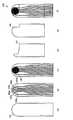
図5に示すバイオセンサ100の構造を図6に示す。図6(a)に示す、絶縁体からなる基板101が準備される。基板101は、ポリエチレンテレフタレートシート、ポリエチレンナフタレートシート、生分解性ポリエステル系樹脂シート、ポリアミドシート、ポリイミドシート、あるいは、セラミック基板などである。 The structure of the
基板101上に図6(b)に示すように、計測電極102a、102b、前方検知電極103a、103b、後方検知電極104a、104bが形成される。計測電極102a、102b、前方検知電極103a、103b、後方検知電極104a、104bは、白金、金、パラジウム、インジウム−スズ酸化物などの導体薄膜により形成される。導体薄膜の形成方法としては、ホットスタンピング、真空蒸着、スパッタリングなどがある。 As shown in FIG. 6B,
計測電極102a、102b、前方検知電極103a、103bの先端部、後方検知電極104a、104bの先端部の上に、図6(c)に示す反応部105が形成される。反応部105は、酸化還元酵素および電子受容体を含む膜である。反応部105は、液体状態の材料を所望の位置に滴下し、乾燥させて形成される。 A
図6(d)にスペーサー107を示す。図6(f)に示すように、基板101上にスペーサー107が載置される。スペーサー107は、計測電極102a、102bの先端、前方検知電極103a、103bの先端、後方検知電極104a、104bの先端、および、反応部105を避けて載置される。 FIG. 6D shows the
図6(e)にカバー108を示す。図6(f)に示すように、スペーサー107の上にカバー108が載置される。カバー108により、計測電極102a、102b、前方検知電極103a、103b、後方検知電極104a、104b、および、反応部105が覆われる。スペーサー107により、カバー108と反応部105は一定間隔(概略スペーサー107の厚さ)で対向する。 FIG. 6E shows the
以上のようにして、図5に示すバイオセンサ100が作製される。 As described above, the
検体(血液など)の供給口106は、バイオセンサ100の先端にある。供給口106に検体が点着されると、検体は反応部105とカバー108の隙間を毛細管現象により進行し、反応部105上に広がる。 A sample (such as blood)
反応部105の上に広がった検体は、反応部105と反応する。このとき、計測電極102a、102b間に電位差が生じ、電子が授受される。反応部105の材料を適正に選択すると、検体の基質成分量に比例した電子の授受が生じる。一対の計測電極102a、102bは、基質成分量を計測することに用いられる。 The specimen spread on the
血液中のグルコース(血糖)を測定する場合、酸化還元酵素として、例えばグルコースオキシターゼ、電子受容体として、例えばフェリシアン化カリウムが用いられる。血液中のグルコース濃度が高いと、計測電極102a、102bの間で授受される電子の量が多くなる。 When measuring glucose (blood glucose) in blood, for example, glucose oxidase is used as an oxidoreductase, and potassium ferricyanide is used as an electron acceptor, for example. When the glucose concentration in the blood is high, the amount of electrons transferred between the
一対の前方検知電極103a、103bの先端は、供給口106近傍に位置する。前方検知電極103a、103b間に電流が流れることにより、検体が供給口106に点着したことが検知される。 The tips of the pair of
一対の後方検知電極104a、104bの先端は、反応部105の後端に位置する。後方検知電極104a、104b間に電流が流れることにより、検体が後方検知電極104a、104bまで到達したことが検知される。これにより、反応部105の上に検体が十分に広がり、所望の反応が行なわれたことが推定される。 The front ends of the pair of
バイオセンサ100は、図7に示すように、計測表示装置200に挿入される。計測表示装置200は、筐体201と画面202を備える。 The
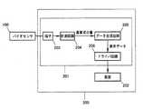
筐体201内に、図8に示すように、端子203、計測回路204、データ生成回路205、ドライバ回路206を備える。端子203には、バイオセンサ100の計測電極102a、102b、前方検知電極103a、103b、後方検知電極104a、104bが接続される。 As shown in FIG. 8, the
計測回路204は、端子203を通じて計測電極102a、102b、前方検知電極103a、103b、後方検知電極104a、104bに所定の電圧を印加する。 The
前方検知電極103a、103b間に流れた電流から検体が供給口106に点着したことが検知される。後方検知電極104a、104b間に流れた電流から、検体が後方検知電極104a、104bまで到達したことが検知される。そして、計測電極102a、102b間に流れた電流から検体の基質成分量が計測される。 From the current flowing between the
データ生成回路205は、基質成分量の表示データを生成する。ドライバ回路206は、画面202に基質成分量を表示させる。 The
バイオセンサ100が計測表示装置200に挿入された後、計測回路204により基質成分量が計測され、画面202に表示される。バイオセンサ100の反応部105は不可逆反応をするため、バイオセンサ100は1回の使用で使えなくなる。そのため、計測ごとにバイオセンサ100は交換される。 After the
計測表示装置200は携帯に容易なように、小型に作られている。画面202も小型であり、僅かの内容しか表示できない。そのため、内容は画面を順次切り替えて表示される。 The
図9に、計測開始から計測完了までの、従来の画面202表示の展開を示す。 FIG. 9 shows the development of the
「OFF状態」では画面202に何も表示されていない。スイッチ207を入れると、画面202は「全画面表示」となる。これは、表示に欠落がないか確認するために用いられる。所定の時間経過後、「全画面表示」から「現在の日付と時間の表示」に変更される。これは、日付と時間に誤りがないか確認するために用いられる。 In the “OFF state”, nothing is displayed on the
バイオセンサ100には、正常な計測のできる適正温度範囲がある。そのため計測表示装置200の温度が適正温度範囲外であるときは、「温度警告」が表示される。しかし計測表示装置200の温度が適正温度範囲内であるときは、「温度警告」は表示されない。 The
次に、バイオセンサ100を計測表示装置200に挿入する指示が表示される。 Next, an instruction to insert the
バイオセンサ100を計測表示装置200に挿入すると、「前回の測定値」が表示される。 When the
所定時間経過後、検体をバイオセンサ100に点着する指示が表示される。 After a predetermined time has elapsed, an instruction to spot the sample on the
検体をバイオセンサ100に点着すると、検体は反応部105の上に広がり、反応部105との反応が進行する。反応には所定の時間(5秒〜10秒程度)が必要である。反応中は、反応完了までの待時間(例えば、「5、4、3、2、1、0」)が表示される。 When the sample is spotted on the
反応が完了して検体の基質成分量の計算が終わると、「測定値」が表示される。これにより、一連の測定が終了する。 When the reaction is completed and the calculation of the amount of the substrate component of the sample is completed, the “measured value” is displayed. Thereby, a series of measurements is completed.
以上の一連の画面表示の展開は、初心者に対して親切であるが、熟練者に対しては無駄が多い。熟練者は、「全画面表示」、「現在の日付と時間の表示」、「バイオセンサ挿入指示」、「前回測定値表示」、「検体点着指示」などは、毎回同じことの繰り返しとして、わずらわしく感じやすい。しかし、計測表示装置200は初心者でも誤操作なく使用できなければならない。そのため、熟練者向けの簡略化した画面表示の展開だけにするわけにいかない。 The development of the above series of screen displays is kind to beginners, but wasteful for skilled people. As for the expert, “full screen display”, “current date and time display”, “biosensor insertion instruction”, “previous measurement value display”, “specimen spotting instruction”, etc. It is easy to feel bothersome. However, the
従来の計測表示装置の画面表示の展開は、初心者でも誤操作なく使用できることを目的として、懇切丁寧に作られている。しかし、熟練者は、毎回同じことの繰り返しのため、わずらわしく感じやすい。本発明の目的は、初心者には懇切丁寧な画面展開を提供し、熟練者には無駄のない画面展開を提供する計測表示装置を実現することである。 The development of the screen display of the conventional measurement display device has been carefully made for the purpose of being able to be used without error by a beginner. However, the skilled person tends to feel bothersome because the same thing is repeated every time. An object of the present invention is to provide a measurement display device that provides a gentle and careful screen development for beginners and a lean screen development for an expert.
(1)本発明の計測表示装置においては、反応部を備えたバイオセンサを筺体に挿入し、反応部に導入した検体の基質の成分量を計測して、筺体に備えた画面に表示する。本発明の計測表示装置は、画面の表示の展開として、初心者向けの「詳細画面展開」と熟練者向けの「簡略画面展開」を有する。本発明の計測表示装置は、「詳細画面展開」と「簡略画面展開」を選択する手段を備え、使用開始時に前記バイオセンサを前記筺体に挿入したとき、前記簡略画面展開が選択される。(1) In the measurement display device of the present invention, a biosensor equipped with a reaction unit is inserted into the housing, the amount of the substrate component of the sample introduced into the reaction unit is measured, and displayed on the screen provided in the housing. The measurement display device of the present invention has “detailed screen development” for beginners and “simplified screen development” for experts as screen display development. The measurement display device of the present invention includes means for selecting “detailed screen development” and “simple screen development”, and the simplified screen development is selectedwhen the biosensor is inserted into the housing at the start ofuse .
(2)本発明の計測表示装置においては、OFF状態から、使用開始時にスイッチを入にしたとき、画面の表示の展開として「詳細画面展開」が選択される。The measuring display apparatus (2) The presentinvention, from the OFF state, when the input switch at the start of use, "Details of Display" isRu is selected as an expansion of a displayscreen.
(3)本発明の計測表示装置においては、「詳細画面展開」は、「全画面表示」、「日付と時間の表示」、「バイオセンサ挿入指示」、「前回測定値表示」、「検体点着指示」、「測定中表示」、「測定値表示」を含む。また、「簡略画面展開」は、「測定中表示」、「測定値表示」を含む。 (3) In the measurement display device of the present invention, “detailed screen development” includes “full screen display”, “date and time display”, “biosensor insertion instruction”, “previous measurement value display”, “specimen point” "Indication of arrival", "Display during measurement", "Measurement value display". “Simplified screen development” includes “measurement display” and “measurement value display”.
(4)本発明の計測表示装置は血糖値計測表示装置である。 (4) The measurement display device of the present invention is a blood glucose level measurement display device.
本発明の計測表示装置は、初心者には懇切丁寧な「詳細画面展開」を提供し、熟練者には無駄のない「簡略画面展開」を提供する。 The measurement display device of the present invention provides a “detailed screen development” that is gentle to beginners and a “simple screen development” that is free to the skilled person.
図1に本発明の計測表示装置10の一例を示す。計測表示装置10は、筐体11と画面12を備える。 FIG. 1 shows an example of a
図2に本発明の計測表示装置10に挿入されるバイオセンサ20の一例を示す。図2に示すバイオセンサ20においては、基板21上に、計測電極22a、22b、前方検知電極23a、23b、後方検知電極24a、24bが形成される。 FIG. 2 shows an example of a
基板21は、ポリエチレンテレフタレートシート、ポリエチレンナフタレートシート、生分解性ポリエステル系樹脂シート、ポリアミドシート、ポリイミドシート、あるいは、セラミック基板などである。 The
計測電極22a、22b、前方検知電極23a、23b、後方検知電極24a、24bは、白金、金、パラジウム、インジウム−スズ酸化物などの導体薄膜により形成される。導体薄膜の形成方法としては、ホットスタンピング、真空蒸着、スパッタリングなどがある。 The
計測電極22a、22b、前方検知電極23a、23bの先端部、後方検知電極24a、24bの先端部の上に、反応部25が形成される。 A
反応部25は、酸化還元酵素および電子受容体を含む膜である。反応部25は、液体状態の材料を所望の位置に滴下し、乾燥させて形成される。 The
基板21上にスペーサー27が載置される。スペーサー27は、計測電極22a、22bの先端、前方検知電極23a、23bの先端、後方検知電極24a、24bの先端、および、反応部25を避けて載置される。 A
スペーサー27の上にカバー28が載置される。カバー28により、計測電極22a、22b、前方検知電極23a、23b、後方検知電極24a、24b、および、反応部25が覆われる。スペーサー27により、カバー28と反応部25は一定間隔(概略スペーサー27の厚さ)で対向する。 A
検体(血液など)の供給口26は、バイオセンサ20の先端にある。供給口26に検体が点着されると、検体は反応部25とカバー28の狭い隙間を毛細管現象により進行し、反応部25上に広がる。 A specimen (blood or the like)
反応部25の上に広がった検体は、反応部25と反応する。このとき、計測電極22a、22b間に電位差が生じ、電子が授受される。反応部25の材料を適正に選択すると、検体の基質成分量に比例した電子の授受が生じる。一対の計測電極22a、22bは、基質成分量を計測することに用いられる。 The specimen spread on the
血液中のグルコース(血糖)を測定する場合、酸化還元酵素として、例えばグルコースオキシターゼ、電子受容体として、例えばフェリシアン化カリウムが用いられる。血液中のグルコース濃度が高いと、計測電極22a、22bの間で授受される電子の量が多くなる。 When measuring glucose (blood glucose) in blood, for example, glucose oxidase is used as an oxidoreductase, and potassium ferricyanide is used as an electron acceptor, for example. When the glucose concentration in the blood is high, the amount of electrons transferred between the
一対の前方検知電極23a、23bの先端は、供給口26近傍に位置する。前方検知電極23a、23b間に電流が流れることにより、検体が供給口26に点着したことが検知される。 The front ends of the pair of
一対の後方検知電極24a、24bの先端は、反応部25の後端に位置する。後方検知電極24a、24b間に電流が流れることにより、検体が後方検知電極24a、24bまで到達したことが検知される。これにより、反応部25の上に検体が十分広がり、所望の反応が行なわれたことが推定される。 The front ends of the pair of
図1に示すように、計測表示装置10にバイオセンサ20が挿入される。筐体11に、図3に示すように、端子13、計測回路14、データ生成回路15、ドライバ回路16を備える。端子13には、バイオセンサ20の計測電極22a、22b、前方検知電極23a、23b、後方検知電極24a、24bが接続される。 As shown in FIG. 1, a
計測回路14は、端子13を通じて計測電極22a、22b、前方検知電極23a、23b、後方検知電極24a、24bに所定の電圧を印加する。前方検知電極23a、23b間に流れた電流から検体が供給口26に点着したことが検知される。後方検知電極24a、24b間に流れた電流から、検体が後方検知電極24a、24bまで到達したことが検知される。そして、計測電極22a、22b間に流れた電流から検体の基質成分量が計測される。 The
データ生成回路15は、基質成分量の表示データを生成する。ドライバ回路16は、画面12に基質成分量を表示させる。バイオセンサ20が計測表示装置10に挿入された後、計測回路14により基質成分量が計測され、画面12に基質成分量が表示される。バイオセンサ20の反応部25は不可逆反応を行なうため、バイオセンサ20は1回の使用で使えなくなる。そのため、計測ごとにバイオセンサ20は交換される。 The
計測表示装置10は携帯に容易なように、小型に作られている。画面12も小型であり、僅かの内容しか表示できない。そのため、内容は画面を順次切り替えて表示される。 The
図4に、計測開始から計測完了までの、本発明の計測表示装置10の画面12表示の展開を示す。 FIG. 4 shows the development of the
「OFF状態」では画面12に何も表示されていない。OFF状態でスイッチ17を入れると、初心者向けの懇切丁寧な「詳細画面展開」となる。スイッチ17を入れないで、バイオセンサ20を挿入すると、熟練者向けの無駄の無い「簡略画面展開」となる。 In the “OFF state”, nothing is displayed on the
(「詳細画面展開」の一例)
スイッチ17を入れると、画面12は「全画面表示」となる。これは、表示ドットに欠落がないか確認するために用いられる。所定の時間経過後、「全画面表示」から「現在の日付と時間の表示」に変更される。これは、日付と時間に誤りがないか確認するために用いられる。(Example of "Detailed screen development")
When the
バイオセンサ20には、正常な計測のできる適正温度範囲(例えば、10℃〜35℃)がある。そのため計測表示装置10の温度が適正温度範囲外であるときは、「温度警告」が表示される。しかし計測表示装置10の温度が適正温度範囲内であるときは、「温度警告」は表示されない。 The
次に、バイオセンサ20を計測表示装置10に挿入する指示が表示される。 Next, an instruction to insert the
バイオセンサ20を計測表示装置10に挿入すると、「前回の測定値」が表示される。 When the
所定時間経過後、検体をバイオセンサ20に点着する指示が表示される。 After a predetermined time has elapsed, an instruction to spot the sample on the
検体をバイオセンサ20に点着すると、検体は反応部25の上に広がり、反応部25との反応が進行する。反応には所定の時間(5秒〜10秒程度)が必要である。反応中は、反応完了までの待時間(例えば、「5、4、3、2、1、0」)が表示される。 When the sample is spotted on the
反応が完了して、検体の基質成分量の計算が終わると、今回の「測定値」が表示される。これにより、一連の測定が終了する。 When the reaction is completed and the calculation of the amount of the substrate component of the sample is completed, the current “measured value” is displayed. Thereby, a series of measurements is completed.
(「簡略画面展開」の一例)
バイオセンサ20を計測表示装置10に挿入すると、電源が自動的に入る。計測表示装置10の温度が適正温度範囲外であるときは、「温度警告」が表示される。しかし計測表示装置10の温度が適正温度範囲内であるときは、「温度警告」は表示されない。(Example of "Simplified screen expansion")
When the
検体をバイオセンサ20に点着すると、検体は反応部25の上に広がり、反応部25との反応が進行する。反応には所定の時間(5秒〜10秒程度)が必要である。反応中は、反応完了までの待時間(例えば、「5、4、3、2、1、0」)が表示される。 When the sample is spotted on the
反応が完了して検体の基質成分量の計算が終わると、「測定値」が表示される。これにより、一連の測定が終了する。 When the reaction is completed and the calculation of the amount of the substrate component of the sample is completed, the “measured value” is displayed. Thereby, a series of measurements is completed.
上記の実施例では、「詳細画面展開」と「簡略画面展開」の選択は、OFF状態でスイッチ17を入れるかバイオセンサ20を挿入するかにより、行なわれた。しかし、「詳細画面展開」と「簡略画面展開」の選択手段はこれに限らない。
例えば、OFF状態でスイッチ17を入れると、「詳細画面展開」と「簡略画面展開」のいずれを選択するかの問い合わせ画面となり、そこでどちらかを選択して進むようにしても良い。あるいは、OFF状態でスイッチ17を1回だけ押すと「詳細画面展開」が選択され、スイッチ17を連続して2回押すと「簡略画面展開」が選択されるようにしても良い。あるいは、スイッチ17だけを押すと「詳細画面展開」が選択され、スイッチ17を隣のボタンと同時に押すと「簡略画面展開」が選択されるようにしても良い。In the above embodiment, the selection of “detailed screen development” and “simple screen development” is performed depending on whether the
For example, when the
上記の実施例では、初回使用時から初心者向けの懇切丁寧な「詳細画面展開」と熟練者向けの無駄の無い「簡略画面展開」を選択する方法を例示している。一方で、該当機器の操作を熟知するためには使用を重ねることが必要であるので、使用開始当初は、OFF状態でスイッチ17を入れる場合、もしくはスイッチ17を入れないで、バイオセンサ20を挿入する場合ともに「詳細画面展開」となる。使用回数を計測・保存する機能を付加しておくことで、事前に指定した回数を超える測定回数に達した場合に、「詳細画面展開」と「簡略画面展開」のいずれを選択するかの問い合わせ画面となり、そこでどちらかを選択して進むようにしても良い。 In the above-described embodiment, a method of selecting a “detailed screen development” for beginners from the first use and a “simple screen development” for experts without waste is illustrated. On the other hand, since it is necessary to repeatedly use in order to fully understand the operation of the device, at the beginning of use, the
指定回数は固定もしくは任意に設定できるようにすると良い。あるいは、使用日数を計測・保存しておき、指定日数を超える測定日数に達した場合に、「詳細画面展開」と「簡略画面展開」のいずれを選択するかの問い合わせ画面となり、そこでどちらかを選択して進むようにしても良い。指定日数は固定もしくは任意に設定できるようにすると良い。あるいは、使用時間を計測・保存しておき、指定時間を超える測定時間に達した場合に、「詳細画面展開」と「簡略画面展開」のいずれを選択するかの問い合わせ画面となり、そこでどちらかを選択して進むようにしても良い。指定時間は固定もしくは任意に設定できるようにすると良い。 The specified number of times should be fixed or arbitrarily settable. Alternatively, the number of days used can be measured and saved, and when the number of days exceeds the specified number of days, an inquiry screen appears asking whether to select "Detailed screen expansion" or "Simplified screen expansion". You may make it select and advance. The specified number of days should be fixed or arbitrarily settable. Alternatively, the usage time is measured and saved, and when the measurement time exceeds the specified time, an inquiry screen is displayed as to whether to select "Detailed screen expansion" or "Simplified screen expansion". You may make it select and advance. The specified time should be fixed or arbitrarily settable.
また、「詳細画面展開」か「簡略画面展開」かを選択できる問い合わせ画面を
画面表示の展開ルーチン中もしくはその展開ルーチン外に設け、その問い合わせ画面にて、どちらかを選択して、以降の操作については、選択された画面表示の展開ルーチンを進むようにしても良い。In addition, an inquiry screen that can be selected as “detailed screen expansion” or “simplified screen expansion” is provided in the expansion routine of the screen display or outside the expansion routine. For the above, the selected screen display expansion routine may be advanced.
本発明により、初心者には懇切丁寧な「詳細画面展開」を提供し、熟練者には無駄のない「省略画面展開」を提供する計測表示装置が実現される。 According to the present invention, a measurement display device is provided that provides a “detailed screen development” that is gentle to beginners and a “abbreviated screen development” that is free to experienced users.
10 計測表示装置
11 筐体
12 画面
13 端子
14 計測回路
15 データ生成回路
16 ドライバ回路
17 スイッチ
20 バイオセンサ
21 基板
22a、22b 計測電極
23a、23b 前方検知電極
24a、24b 後方検知電極
25 反応部
26 供給口
27 スペーサー
28 カバー
100 バイオセンサ
101 基板
102a、102b 計測電極
103a、103b 前方検知電極
104a、104b 後方検知電極
105 反応部
106 供給口
107 スペーサー
108 カバー
200 計測表示装置
201 筐体
202 画面
203 端子
204 計測回路
205 データ生成回路
206 ドライバ回路
207 スイッチDESCRIPTION OF
Claims (4)
Translated fromJapanese前記画面の表示の展開として詳細画面展開と簡略画面展開を有し、前記詳細画面展開と簡略画面展開を選択する手段を備え、
使用開始時に前記バイオセンサを前記筺体に挿入したとき、前記簡略画面展開が選択されることを特徴とする計測表示装置。A biosensor provided with a reaction part is inserted into a housing, and the amount of a component of a substrate of a sample introduced into the reaction part is measured and displayed on a screen provided in the housing,
There are detailed screen expansion and simplified screen expansion as the display expansion of the screen, comprising means for selecting the detailed screen expansion and the simplified screen expansion,
The measurement display device, wherein the simplified screen development is selected when the biosensor is inserted into the housing at the start of use .
前記簡略画面展開は、「測定中表示」、「測定値表示」を含むことを特徴とする、請求項1または2に記載の計測表示装置。The detailed screen development includes “full screen display”, “date and time display”, “biosensor insertion instruction”, “previous measurement value display”, “specimen spotting instruction”, “measurement display”, “measurement value” Including "
The measurement display device according to claim 1, wherein the simplified screen expansion includes “display during measurement” and “measurement value display”.
Priority Applications (1)
| Application Number | Priority Date | Filing Date | Title |
|---|---|---|---|
| JP2011046299AJP5722667B2 (en) | 2011-03-03 | 2011-03-03 | Measurement display device |
Applications Claiming Priority (1)
| Application Number | Priority Date | Filing Date | Title |
|---|---|---|---|
| JP2011046299AJP5722667B2 (en) | 2011-03-03 | 2011-03-03 | Measurement display device |
Publications (2)
| Publication Number | Publication Date |
|---|---|
| JP2012184937A JP2012184937A (en) | 2012-09-27 |
| JP5722667B2true JP5722667B2 (en) | 2015-05-27 |
Family
ID=47015171
Family Applications (1)
| Application Number | Title | Priority Date | Filing Date |
|---|---|---|---|
| JP2011046299AExpired - Fee RelatedJP5722667B2 (en) | 2011-03-03 | 2011-03-03 | Measurement display device |
Country Status (1)
| Country | Link |
|---|---|
| JP (1) | JP5722667B2 (en) |
Family Cites Families (8)
| Publication number | Priority date | Publication date | Assignee | Title |
|---|---|---|---|---|
| JPH07128338A (en)* | 1993-11-02 | 1995-05-19 | Kyoto Daiichi Kagaku:Kk | Convenient blood sugar meter and data managing method therefor |
| JPH0844520A (en)* | 1994-07-29 | 1996-02-16 | Toshiba Corp | Interactive device and operation guidance output method applied to the device |
| US5665215A (en)* | 1995-09-25 | 1997-09-09 | Bayer Corporation | Method and apparatus for making predetermined events with a biosensor |
| JP4688365B2 (en)* | 2001-08-09 | 2011-05-25 | パナソニック株式会社 | measuring device |
| JP2004016752A (en)* | 2002-06-20 | 2004-01-22 | Konami Sports Life Corp | Exercise assisting device and program used for exercise assisting device |
| US20080133146A1 (en)* | 2004-12-17 | 2008-06-05 | Chang Kc Shu Kun | Device Having a Trend-Indicating Display |
| US20090076360A1 (en)* | 2007-09-13 | 2009-03-19 | Dexcom, Inc. | Transcutaneous analyte sensor |
| EP2130487A1 (en)* | 2008-06-03 | 2009-12-09 | Microlife Intellectual Property GmbH | Glucose meter, a system with a glucose meter, method for operating a glucose meter and a computer program product |
- 2011
- 2011-03-03JPJP2011046299Apatent/JP5722667B2/ennot_activeExpired - Fee Related
Also Published As
| Publication number | Publication date |
|---|---|
| JP2012184937A (en) | 2012-09-27 |
Similar Documents
| Publication | Publication Date | Title |
|---|---|---|
| TWI227066B (en) | Electrochemical cell | |
| KR102035990B1 (en) | Accurate analyte measurements for electrochemical test strip based on sensed physical characteristic(s) of the sample containing the analyte | |
| US5320732A (en) | Biosensor and measuring apparatus using the same | |
| CN102520029B (en) | A system and method of processing a current sample for calculating a glucose concentration | |
| JP5745835B2 (en) | Filling sufficiency method and system | |
| CN105556298B (en) | Abnormal signal error capture for analyte measurement | |
| KR101966611B1 (en) | Glucose electrochemical measurement method with error detection | |
| EP3051280A1 (en) | Metal oxide based gas sensor with pulsed heating | |
| KR101956581B1 (en) | Peak offset correction for analyte test strip | |
| CN103415767A (en) | Capacitive detection in electrochemical analysis with improved sample time offset | |
| KR20160003208A (en) | Analytical test meter | |
| JP2008264024A (en) | Occlusion characteristic analyzing apparatus and occlusion characteristic analyzing method | |
| JP2019533159A (en) | Method and apparatus for correcting uncompensated resistance of conductive element of biosensor | |
| JP5988965B2 (en) | Analytical test strip with electrodes having electrochemically active and inactive regions of a predetermined size and distribution | |
| CN105579837B (en) | For the transient signal mistake trapping according to the analysis measurement that predetermined sampling time interval determines derived from the sensing physical characteristic of the sample of analyte-containing | |
| JP5722667B2 (en) | Measurement display device | |
| CN105358969B (en) | Analyte measurement system and method of determining sample filling errors in a biosensor | |
| TW201430342A (en) | A detecting device and method for electrochemical sensing strips | |
| EP2781914A1 (en) | Method for measuring hematocrit levels, quantitative analysis method using said measurement method, and sensor chip | |
| JP5452436B2 (en) | Measurement display device | |
| TWI603083B (en) | System and method for measuring an analyte in a sample and calculating hematocrit-insensitive glucose concentrations | |
| JP4873170B2 (en) | Measurement display to which a biosensor is connected | |
| JP5895404B2 (en) | Measuring apparatus and measuring method | |
| CN103675047A (en) | Biosensor calibration method | |
| JP5073629B2 (en) | Measurement display device to which biosensor is attached and measurement method |
Legal Events
| Date | Code | Title | Description |
|---|---|---|---|
| A621 | Written request for application examination | Free format text:JAPANESE INTERMEDIATE CODE: A621 Effective date:20140115 | |
| A977 | Report on retrieval | Free format text:JAPANESE INTERMEDIATE CODE: A971007 Effective date:20140709 | |
| A131 | Notification of reasons for refusal | Free format text:JAPANESE INTERMEDIATE CODE: A131 Effective date:20140729 | |
| A521 | Written amendment | Free format text:JAPANESE INTERMEDIATE CODE: A523 Effective date:20140918 | |
| TRDD | Decision of grant or rejection written | ||
| A01 | Written decision to grant a patent or to grant a registration (utility model) | Free format text:JAPANESE INTERMEDIATE CODE: A01 Effective date:20150225 | |
| A61 | First payment of annual fees (during grant procedure) | Free format text:JAPANESE INTERMEDIATE CODE: A61 Effective date:20150326 | |
| R150 | Certificate of patent or registration of utility model | Ref document number:5722667 Country of ref document:JP Free format text:JAPANESE INTERMEDIATE CODE: R150 | |
| R250 | Receipt of annual fees | Free format text:JAPANESE INTERMEDIATE CODE: R250 | |
| LAPS | Cancellation because of no payment of annual fees |